

Climecon CLEANMASTER Series Installation, Adjustment, Operating And Maintenance Instructions
Page 1

www.climecon.fi
09.16
© Climecon
INSTALLATION, ADJUSTMENT,
OPERATING AND MAINTENANCE
INSTRUCTIONS OF
CLEANMASTER® HOODS
Lämmittäjänkatu 4 A, FI-00880 HELSINKI, Finland · Telephone +358 20 198 6600, Fax +358 020 198 6609
1
Page 2

Contents
1. General ..................................................................................................... 1
1.1 Safety at work and safe installation of the product ........................................2
1.2 Receiving the goods ..........................................................................................2
1.3 Warnings ...........................................................................................................2
2. Content of the Cleanmaster® hood delivery ................................................ 3
3. Instructions for installation of Cleanmaster® hoods ....................................3
3.1 Installation of the hood ....................................................................................3
3.2 Installation of the air flow sensor ................................................................... 4
3.3 Installation of the CCM control unit ............................................................... 4
3.4 Electrical wiring ............................................................................................... 4
3.5 Replacing the UV-lamp ....................................................................................5
3.6 Installation of grease filters and locking the SlideSafe safety lock...............5
3.7 Before you start the CleanMaster® system ....................................................5
3.8 Starting the CleanMaster® system ................................................................ 6
4. Instructions for adjustment of Cleanmaster® hoods ...................................6
4.1 Adjusting the supply air, exhaust air and capture air flow ............................. 6
4.2 Table of the K-values of CleanMaster® hoods ................................................7
4.3 Calibration of the air flow sensor ....................................................................7
5. Operating instructions for Cleanmaster® hoods ..........................................8
5.1 Functions of the control panel of the CCM control unit ................................. 8
5.2 Fault conditions of the CleanMaster® system ............................................... 8
6. Instructions for maitenance of Cleanmaster® hoods ...................................9
6.1 Cleaning the hood ............................................................................................ 9
6.2 Removing the grease filters ........................................................................... 9
6.3 Replacing the fluorescent tubes in the lights ................................................ 9
6.4 Replacing the UV lamp ..................................................................................10
www.climecon.fi
© Climecon 2
Lämmittäjänkatu 4 A, FI-00880 HELSINKI, Finland · Telephone +358 20 198 6600, Fax +358 020 198 6609
Page 3

1. GENERAL
These are the installation, adjustment and maintenance instructions for Climecon CleanMaster® hoods.
The model range of Climecon CleanMaster® hoods includes:
• CleanMaster® hoods
• CleanMaster® hoods with capture air
• CleanMaster® hoods with supply air and capture air
Make sure you read and understand these installation, adjustment and maintenance instructions before starting to install and use the product. If you have any questions about the installation or operation of the product, please contact the Climecon customer service.
Climecon Oy
Lämmittäjänkatu 4 A
00880 HELSINKI
Puh 020 198 6600
Fax 020 198 6609
www.climecon.fi
1.1 Safety at work and safe installation of the product
Failure to observe these operating and safety instructions during operation, disregarding
these instructions or using the UV equipment not as specified can result in injuries!
NOTE! The electrical connection of the CleanMaster® system may only be carried out by an
authorized electrician. Warranty is subject to the condition of using Climecon spare parts and
UV lamps. Only the original parts or the spare parts or UV lamps ordered from Climecon may
be used in the device. The UV lamps should always be ordered from Climecon customer service
(tel. 020 198 6600).
Ultraviolet radiation and ozone are hazardous to health! The areas which are especially
exposed to the ultraviolet radiation are the skin and eyes. The radiation can cause burns and a
long-term exposure can result in a cataract. Always make sure that the UV lamps are turned
o when removing the grease filters!
ALWAYS wear safety goggles and safety gloves during installation for protection against
quartz fragments, which can become scattered around if the UV lamp breaks.
1.2 Receiving the goods
Check that the delivered product batch is according to your order and all the parts stated in
the delivery note are included. The carrier of the cargo should be informed immediately about
errors in the delivery and incorrect delivery as well as possible damages occurred during transportation, and the respective notice should also be sent to Climecon or the distributor.
The term of notice is 5 days from delivery. Climecon Oy shall take no responsibility for costs
arising from the replacement of products, which had not been installed according to the installation instructions.
In case of problems you should contact the Climecon customer service!
© Climecon 3
Lämmittäjänkatu 4 A, FI-00880 HELSINKI, Finland · Telephone +358 20 198 6600, Fax +358 020 198 6609
Page 4
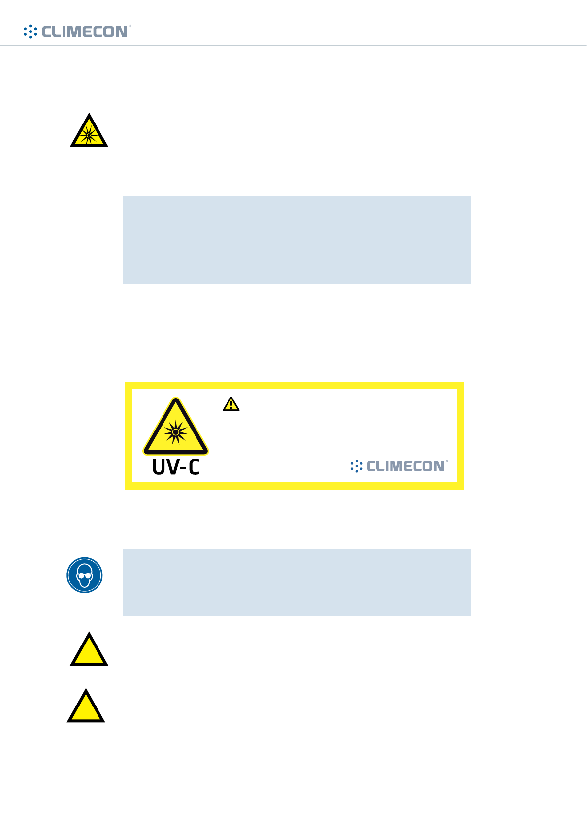
1.3 Warnings
UV light and ozone are harmful
The areas which are especially exposed to the UV light are the skin and
eyes. The light can cause burns and a long-term exposure can result in a
cataract; UV light damages the lens and cornea of the eyes.
BEFORE STARTING TO REMOVE THE GREASE FILTERS,
ALWAYS MAKE SURE THAT THE UV-LAMPS ARE SWITCHED OFF!
CAREFULLY READ THE OPERATING INSTRUCTIONS!
www.climecon.fi
The warning label shown in the figure is attached to a visible
place on the product already in the factory. Stick the other label included in the package next to the UV Multi control unit.
Varoitus/Caution
• Tämä keittiöhuuva on varustettu UV/otsoni puhdistinjärjestelmällä
• Kytke virta pois ennen kuin poistat rasvasuotimia
• UV-valo voi vahingoittaa silmiä ja ihoa
• This kitchen hood is equipped with UV/ozone purifying system
• Shut down the system before removing grease filters
• UV light is harmful for eyes and skin
USE PROTECTIVE GLASSES AND PROTECTIVE
GLOVES IN ALL INSTALLATION RELATED WORKS
(rupture of a pipe can cause quartz shards)
!
!
© Climecon 4
The electrical connections of the CleanMaster® system may only be
made by an authorized electrician.
Only the Climecon spare parts and UV lamps may be used in the
CleanMaster® system.
Lämmittäjänkatu 4 A, FI-00880 HELSINKI, Finland · Telephone +358 20 198 6600, Fax +358 020 198 6609
Page 5

www.climecon.fi
2. CONTENT OF THE CLEANMASTER® HOOD DELIVERY
The delivery includes the following:
• Hood according to order confirmation
• Grease filters
• Grease pan(s)
• CCM control unit and possible slave units
• Air flow sensor
• UV lamps according to the system, each with a ready installed quick coupling
• Wiring diagrams according to the system
• Safety switch (delivered detached)
• Warning labels for the hood
• Installation, adjustment, operating and maintenance instructions
The delivery does not include:
• Voltage conductor (e.g. MMJ 3G2.5) for the UV control unit
• Voltage conductor between the UV control unit and a possible extra cabinet
• Supply of the voltage of UV lamps from the terminal block of the UV control unit to
the quick couplings of the hood (e.g. control wire Ölfex 4 x 1.5mm2)
• Fasteners
• Wires for the SlideSafe safety lock
© Climecon 5
Lämmittäjänkatu 4 A, FI-00880 HELSINKI, Finland · Telephone +358 20 198 6600, Fax +358 020 198 6609
Page 6
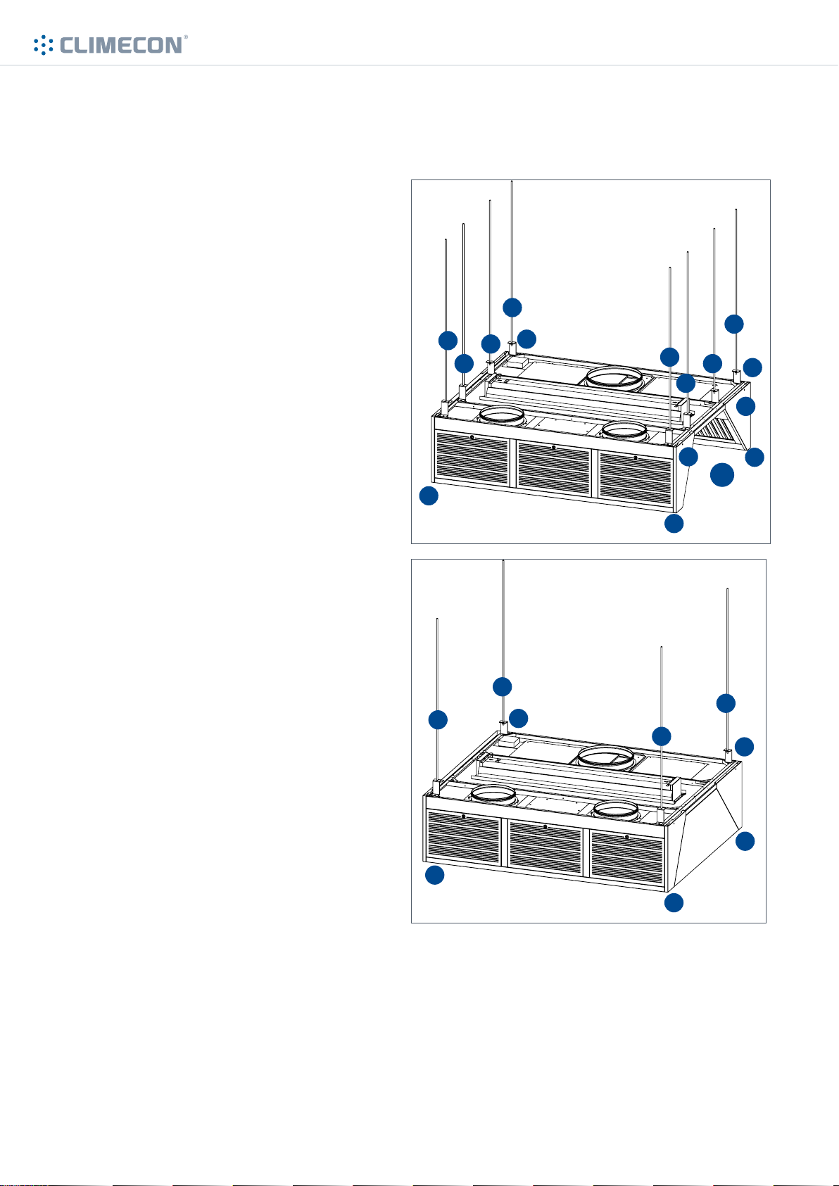
3. INSTRUCTIONS FOR INSTALLATION OF
CLEANMASTER® HOODS
3.1 Installation of the hood
1. Mount the thread bars (A) to the cor-
rect positions in the ceiling. NOTE!
Thread bars are not included in delivery!
If the hood features an open side (AR),
the hood should also be supported from
the middle of the open side (B).
2. Lift the hood up from the corners (C),
keeping it steady
3. Install adaptor brackets (D) to the
thread bars and the hood
4. Check that the hood is horizontally
5. Remove any possible transportation
supports
6. Fix adjacent hoods to one another
through the holes (E) in the upper edge
of each hood, using M6 bolts and nuts.
A
B
C
A
C
B
www.climecon.fi
A
B
B
E
AR
C
A
D
E
C
A
A
A
C
C
A
C
D
C
© Climecon
Lämmittäjänkatu 4 A, FI-00880 HELSINKI, Finland · Telephone +358 20 198 6600, Fax +358 020 198 6609
6
Page 7
www.climecon.fi
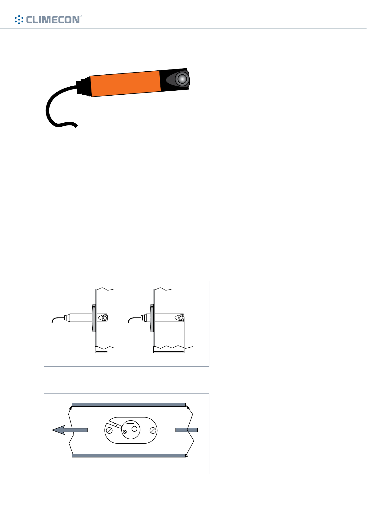
3.2 Installation of the air flow sensor
The air flow sensor is delivered together with the CCM control unit.
1. Find a suitable place for the air flow sensor in the exhaust air duct. It is recommended to install
it in a straight section of the duct (less turbulence), preferably not on the bottom of the duct.
2. Drill a Ø24mm hole into the duct.
3. Fix the air flow sensor to a mounting plate. Adjust the installation depth according to the dia-
meter of the exhaust air duct. It is recommended to install it in the centre of the duct (Figure 1).
4. Make sure that the air flow sensor is installed according to the air flow direction. See the arrow
at the bottom of the sensor (Figure 2).
5. Drill pilot holes for the fixing screws of the mounting plate.
6. Fix the air flow sensor to the duct.
Figure 1. Installation depth of air flow sensor
min. 32 mm approx. 120 mm
Figure 2. Installation direction of the air flow sensor
Installation direction of the air flow sensor
© Climecon 7
Lämmittäjänkatu 4 A, FI-00880 HELSINKI, Finland · Telephone +358 20 198 6600, Fax +358 020 198 6609
Page 8

www.climecon.fi
3.3 Installation of the CCM control unit
Start with the installation of the CCM control unit by looking at the wiring diagram included in the
delivery.
1. The CCM control unit and possible slave units should be mounted on a wall in a visible place
which can be easily accessed.
2. Mount the safety switch included in delivery on a wall near the CCM control unit, where the
switch can be easily accessed.
3.4 Electrical wiring
3.4.1 Electrical wiring of the CCM control unit
1. Lead the voltage supply to the safety switch.
2. From the safety switch lead the voltage supply to the CCM control unit and to possible slave
units.
3. Connect the conductors coming out from the CCM control unit to the UV lamp. following the
wiring diagram provided at the end of these instructions.
4. Connect the conductors of the SlideSafe safety lock of the hoods to the CCM control unit or a
slave unit.
3.4.2 Connecting the CCM control unit with the automation system of the building
The CCM control unit gives the possibility to send operational information to the automation system of the real estate, and to request starting permission, if necessary. Detailed information is
provided in the wiring diagram at the end of these instructions.
Output:
Operating status
• The system functions normally. A green light is lit in the control panel.
Common alarm
• Alarm, the system has switch o. A red light is lit in the control panel.
Warning
• Warning, action by the user is required. The system still functions.
A yellow light is lit in the control panel.
Input:
External control
• The building automation has not given the permission for operation.
A red light is lit in the control panel.
© Climecon 8
Lämmittäjänkatu 4 A, FI-00880 HELSINKI, Finland · Telephone +358 20 198 6600, Fax +358 020 198 6609
Page 9
www.climecon.fi
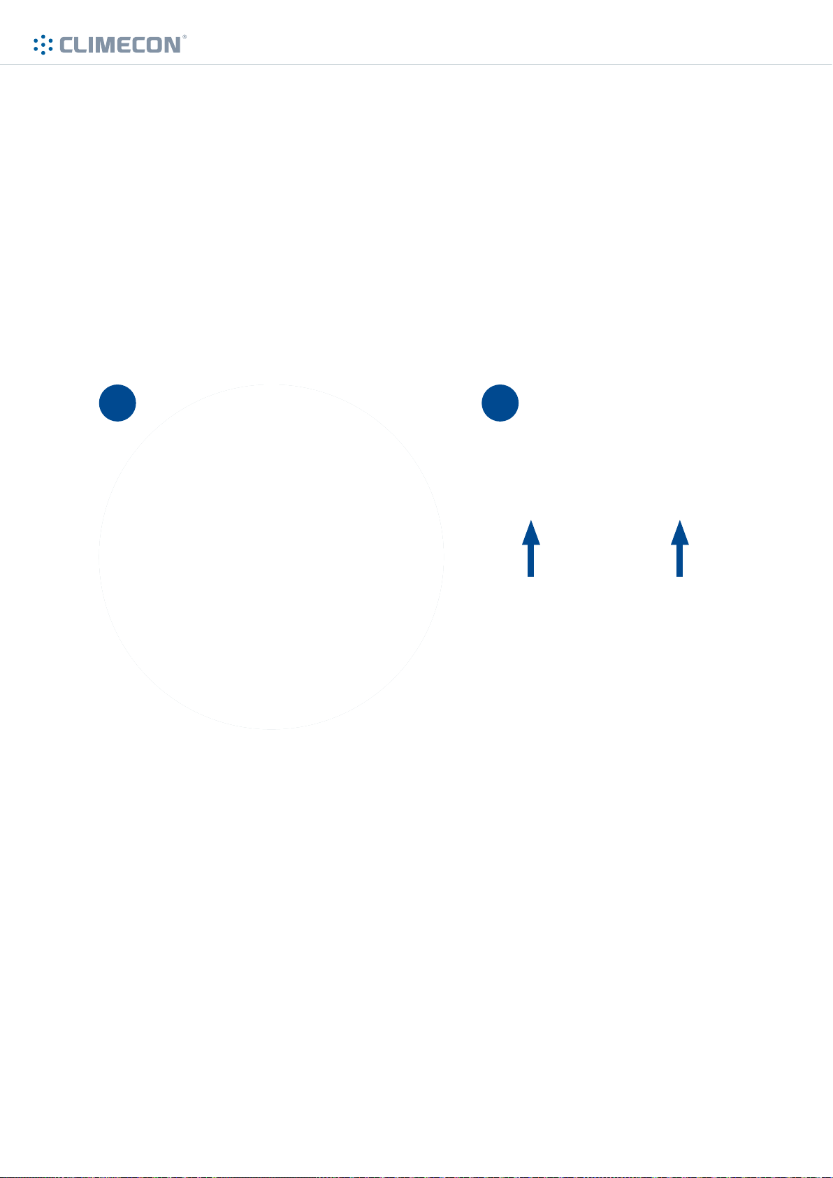
3.5 Replacing the UV-lamp
1. Carefully secure the UV lamp to the holders in the grease chamber of the hood.
Note! The holders should remain in the centre of the blue plastic parts of the lamp. Tighten
the holders with the fixing screws.
2. Connect the quick connector of the electricity conductor of the lamp to the counter piece in
the ceiling of the hood. Turn the locking ring of the connector.
Note! Attach the labels about UV lamp replacement and maintenance instructions of the
hood, which were included in the delivery, to a visible place close to the CCM control unit.
21
© Climecon
Lämmittäjänkatu 4 A, FI-00880 HELSINKI, Finland · Telephone +358 20 198 6600, Fax +358 020 198 6609
9
Page 10
www.climecon.fi
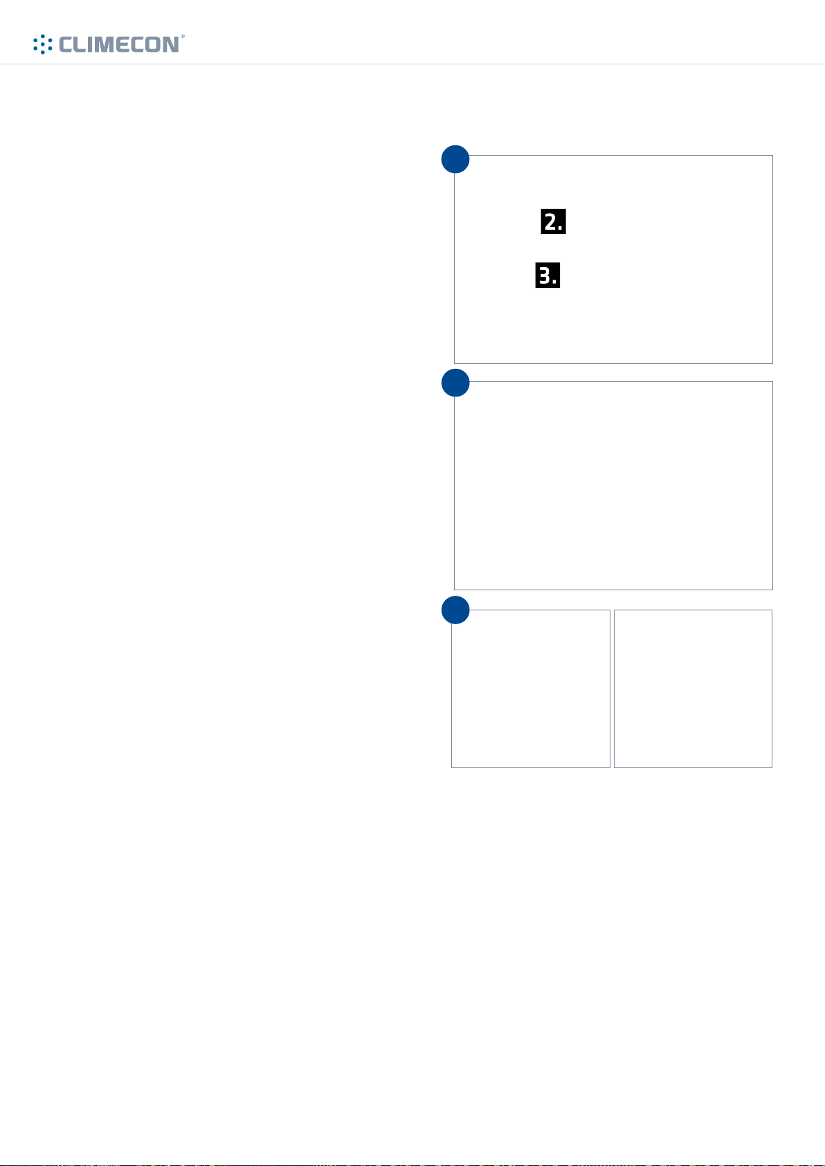
3.6 Installation of grease filters and locking the SlideSafe safety lock
1. First install the grease filters at far
edges, leaving the second grease filter
from the left as the last. Install also
the grease pans at the bottom of the
exhaust air chamber.
2. Move the grease filter on far left more
to the right.
3. Lock the SlideSafe safety lock by first
lifting the hand screws to the upper
position and then tightening the
screws.
NOTE! The CleanMaster® system will
not start, when the SlideSafe safety
lock has not been properly locked.
1
2
3
© Climecon
Lämmittäjänkatu 4 A, FI-00880 HELSINKI, Finland · Telephone +358 20 198 6600, Fax +358 020 198 6609
10
Page 11

www.climecon.fi
3.7 Before you start the CleanMaster® system
Check the following points before starting the CleanMaster® system:
• UV lamps are correctly installed
• Wires led from the UV lamps are connected through their quick connections to sockets in the
hood, and tightened
• The wires of UV lamps and SlideSafe safety lock from the UV control unit to the terminal block
box of the hood are fixed from both ends with a screw
• The air flow sensor has been installed in the ventilation duct and adjusted
• A maintenance / safety switch has been installed to supply voltage line before the UV control unit
• All grease filters have been installed and the safety lock of grease filters has been locked
• The labels about UV lamp replacement and maintenance instructions of the hood, which were
included in the delivery, have been attached to a visible place near the hood
3.8 Starting the CleanMaster® system
Start the CleanMaster® system by turning the main switch of the CCM control unit to ON-position.
After the start, the text «restart» appears on the display of the UV system, after which in about 60
seconds the starters of UV lamps become active (starting delay of the air flow sensor).
© Climecon 11
Lämmittäjänkatu 4 A, FI-00880 HELSINKI, Finland · Telephone +358 20 198 6600, Fax +358 020 198 6609
Page 12

www.climecon.fi
When the UV system has been switched on,
the UV lamps are preheated for 12 seconds.
During the preheating a yellow LED is illuminated on the right side of the display.
After the preheating, the UV system starts to
function normally.
At this stage all UV lamps are on and a green LED
is illuminated on the right side of the display.
If any of the UV lamps stops working due to a
defect or a fault, the UV system display informs
about the lamp fault.
At this stage the faulty UV lamp should be checked
and replaced, if necessary.
New UV lamps should always be ordered directly
from Climecon customer service!
© Climecon 12
Lämmittäjänkatu 4 A, FI-00880 HELSINKI, Finland · Telephone +358 20 198 6600, Fax +358 020 198 6609
Page 13
123,0
123,0
6
1
2
3
4
5
7
4. INSTRUCTIONS FOR ADJUSTMENT OF
CLEANMASTER® HOODS
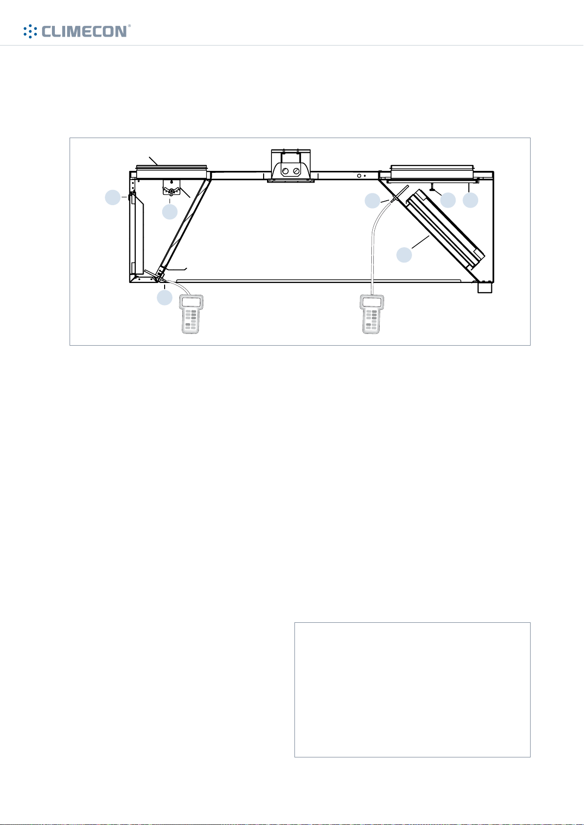
4.1 Adjusting the supply air, exhaust air and capture air flow
www.climecon.fi
Adjusting the supply air flow
• First measure the pressure drop at the
measuring connection (5) of the supply air
chamber
• Remove supply air modules (6), using a
screwdriver
• Adjust the supply air by turning the adjusting
damper (7) inside the supply air chamber
• Lock the adjusting damper with a locking
screw
• Re-install the supply air modules (6) to their
places
• Measure the pressure drop at the measuring
connection (5) of the supply air chamber
• Repeat the above procedure, if necessary
Adjusting the exhaust air flow
• Carefully remove the grease filter cartridge
(1) by pushing its bottom edge inwards while
lifting the upper edge up and away from the
mounting groove
• Open the locking screw (3) of the adjusting
damper (4)
• Increase or decrease the suction opening by
moving the damper in its sliding rails
• Install properly the filter cartridge(s)
• Measure the pressure drop at the measuring
connection (2) of the chamber
• Repeat the above procedure, if necessary
• Finally lock the damper with a locking screw
and check that the filter cartridges are properly
in position
Adjusting the capture air
The thrust length of capture air can
be adjusted. You can adjust the thrust
by first turning the hand screws of
the capture air unit, then moving the
screws sideways and finally locking in
position by tightening the hand screws.
© Climecon
Lämmittäjänkatu 4 A, FI-00880 HELSINKI, Finland · Telephone +358 20 198 6600, Fax +358 020 198 6609
13
Page 14
www.climecon.fi
4.2 Table of the K-values of CleanMaster® hoods
Exhaust air / Amount of grease filters (pcs)
Hood model 1 2 3 4 5 6 7 8 9 10 11 12
CleanMaster® 18,5 37 55,5 74 92,5 111 129,5 148 166,5 185 203,5 222
StandardPlus, grease 21,6 43,2 64,8 86,4 108 129,6 151,2 172,8 194,4 216 237,6 259,2
StandardPlus, condensate 22,7 45,4 68,1 90,8 113,5 136,2 158,9 181,6 204,3 227 249,7 272,4
Supply air / Width of the hood (mm)
Height of the hood 800 1000 1500 2000 2500 3000
H=560 mm 28 45 67 90 112 135
H=400 mm 22 42 64 85 106 127
H=300 mm 22 33 49 66 82 99
Capture air / Width of the hood (mm)
Adjustment position 800 1000 1500 2000 2500 3000
Maksimi (Fully open) 1,4 2,8 4,2 5,6 7,0 8,4
Minimi (Fully open)* 0,6 1,2 1,8 2,4 3,0 3,6
*Is only recommended if the pressure of the supply air is over 15Pa.
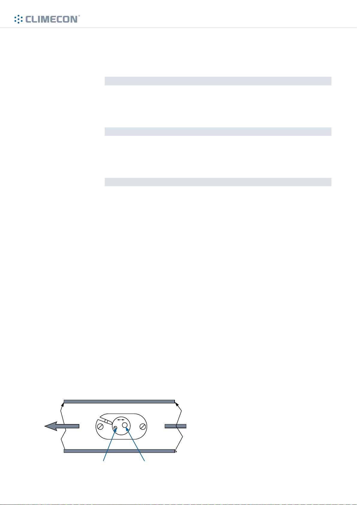
4.3 Calibration of the air flow sensor
Before you start calibrating the air flow sensor, check that
• the CCM control unit is installed
• ventilation has been adjusted and functions normally
1. Switch on the CCM control unit.
2. The air flow sensor measures the air flow for 60 seconds, during which both of the signal lights
are illuminated. When measuring is completed, one of the lights goes o.
a) If a red light is illuminated:
Turn the adjusting screw slowly to the right, until the red light goes o and the green led is illuminated. Then turn the adjusting screw a further 1/2 round to the right.
b) If a green light is illuminated:
Turn the adjusting screw slowly to the left, until the green light goes o and the red light is
illuminated. Then turn the adjusting screw a further 1/2 round to the right, until the green light
is illuminated.
When the air flows change in the system, repeat the calibration of the air flow sensor.
Figure 1. Calibration of the air flow sensor
Adjusting screw
© Climecon 14
Lämmittäjänkatu 4 A, FI-00880 HELSINKI, Finland · Telephone +358 20 198 6600, Fax +358 020 198 6609
Signal lights (red/green)
Page 15

5. OPERATING INSTRUCTIONS FOR
CLEANMASTER® HOODS
5.1 Functions of the control panel of the CCM control unit
Functions of the keys:
www.climecon.fi
INFO
ON/OFF
ARROW
DOWN
MENU
REMOTE
• changes the display screens
(Main Menu, filtering hours/
operating time/hours, meter
screen, depending on settings)
• cursor up in menu
• changes values (higher)
• to On/O menu
• cursor to the right
• cursor down in menu
• changes values (lower)
• to menus
• selection of a function
• confirms a change
• local/remote operation (NOTE! the display should read ”local”)
• cursor to the left
5.2 Fault conditions of the CleanMaster® system
In a fault situation, the colour of the display of the CCM control unit and the colour of LED lights
change into yellow or red, depending on the situation:
YELLOW LIGHT
Text on the screen: lamp age warning
The service hours of the UV lamp are approaching the end.
Order a new UV lamp from the Climecon customer service, tel. 020 198 6600.
Text on the screen: lamp age exceeded
The service hours of the UV lamp have been exceeded. Replace the old UV lamp with a
new UV lamp ordered from Climecon. See the instructions for replacing the UV lamp in
subsection 6.4.
RED LIGHT
Text on the screen: lamp age exceeded
The service hours of the UV lamp have been exceeded. Replace the old UV lamp with a
new UV lamp ordered from Climecon. See the instructions for replacing the UV lamp in
subsection 6.4.
© Climecon 15
Lämmittäjänkatu 4 A, FI-00880 HELSINKI, Finland · Telephone +358 20 198 6600, Fax +358 020 198 6609
Page 16
5. OPERATING INSTRUCTIONS FOR
CLEANMASTER® HOODS
5.1 Functions of the control panel of the CCM control unit
Functions of the keys:
www.climecon.fi
INFO
ON/OFF
ARROW
DOWN
MENU
REMOTE
• changes the display screens
(Main Menu, filtering hours/
operating time/hours, meter
screen, depending on settings)
• cursor up in menu
• changes values (higher)
• to On/O menu
• cursor to the right
• cursor down in menu
• changes values (lower)
• to menus
• selection of a function
• confirms a change
• local/remote operation (NOTE! the display should read ”local”)
• cursor to the left
5.2 Fault conditions of the CleanMaster® system
In a fault situation, the colour of the display of the CCM control unit and the colour of LED lights
change into yellow or red, depending on the situation:
YELLOW LIGHT
Text on the screen: lamp age warning
The service hours of the UV lamp are approaching the end.
Order a new UV lamp from the Climecon customer service, tel. 020 198 6600.
Text on the screen: lamp age exceeded
The service hours of the UV lamp have been exceeded. Replace the old UV lamp with a
new UV lamp ordered from Climecon. See the instructions for replacing the UV lamp in
subsection 6.4.
RED LIGHT
Text on the screen: lamp age exceeded
The service hours of the UV lamp have been exceeded. Replace the old UV lamp with a
new UV lamp ordered from Climecon. See the instructions for replacing the UV lamp in
subsection 6.4.
© Climecon 16
Lämmittäjänkatu 4 A, FI-00880 HELSINKI, Finland · Telephone +358 20 198 6600, Fax +358 020 198 6609
Page 17
6. INSTRUCTIONS FOR MAINTENANCE OF
CLEANMASTER® HOODS
Due to hygiene and fire safety in the kitchen, but also to ensure that the ventilation functions it
is important to keep the kitchen equipment clean. The cleaning interval of Climecon CleanMaster® hoods depends on their use and should be determined on the basis of the level of use.
The hoods can be cleaned with cleaning agents, which are suitable for cleaning stainless steel.
Extremely strong alkali (pH > 11) should be avoided. The Climecon UV lamps do not need cleaning
in case of normal use.
6.1 Cleaning the hood
1. The surfaces of the hood should be cleaned by wiping lightly.
2. Clean the side troughs and grease pans of the hood. Grease pans are machine-washable.
3. Gently wipe the covering glass of lights, if necessary.
4. Clean the exhaust air chamber, if necessary.
See the instructions for removing the grease filters in subsection 6.2 Removing the grease
filters.
5. Clean the supply air modules, if necessary.
www.climecon.fi
Supply air modules can be easily removed by opening first the fixing mechanism at the top of
the module with the help of a screwdriver and then pulling the supply air module away from the
supply air unit.
Supply air modules are machine-washable.
© Climecon 17
Lämmittäjänkatu 4 A, FI-00880 HELSINKI, Finland · Telephone +358 20 198 6600, Fax +358 020 198 6609
Page 18
6.2 Removing the grease filters
www.climecon.fi
1
4
5
2 3
1. Shut down the CleanMaster® system by turning the main switch of the CCM control system
to OFF position.
2. Open the safety locking of grease filters by loosening the hand screws on the left side of the filters.
3. Slide the hand screws to the lower position. NOTE! If the CleanMaster® system was not shut
down from the CCN control unit as instructed, the CleanMaster® system will now shut down
automatically.
4. Move the grease filter on far left more to the left.
5. First remove the second grease filter from the left and then the other grease filters.
Grease filters are machine-washable. Clean the exhaust air chamber if necessary.
6.3 Replacing the fluorescent tubes in the lights
1. Open the covering glass of the lights by opening the fixing screws.
2. Replace the fluorescent tubes.
3. Check that the gaskets are in good condition.
4. Re-install the covering glass.
© Climecon
Lämmittäjänkatu 4 A, FI-00880 HELSINKI, Finland · Telephone +358 20 198 6600, Fax +358 020 198 6609
18
Page 19
6.4 Replacing the UV lamp
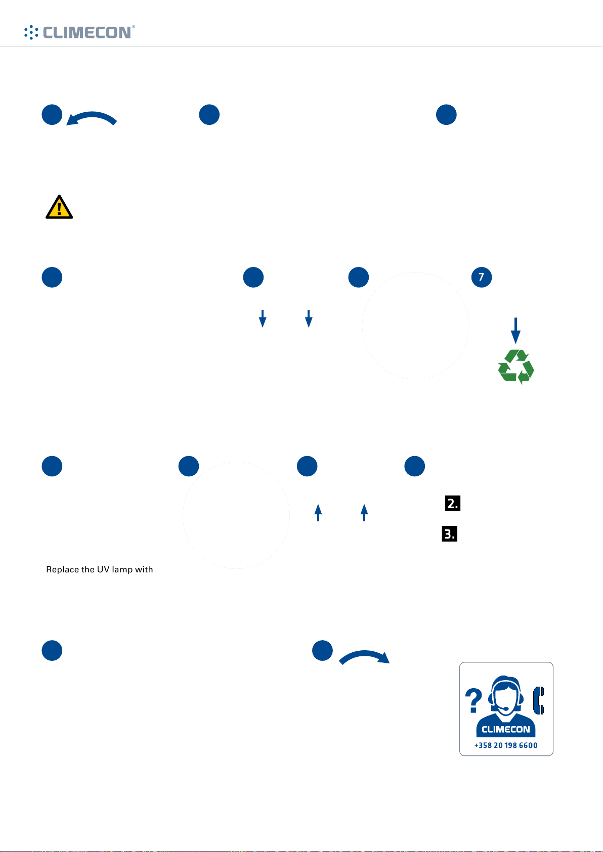
2 31
www.climecon.fi
Shut down the CleanMaster
by turning the main switch of the
CCM control unit to OFF position.
®
system
4
First remove the second grease filter from the left and then the other
grease filters.
8
9 10 11
Open the SlideSafe safety lock by loosening the
hand screws and moving these to the lower position.
5 6
Remove the electrical connector (quick connector) of the UV
lamp from the ceiling of the
hood by turning the connector
counter clockwise.
Turn the hand screws of
the supports of the UV
lamp counter clockwise
and remove the UV lamp
from the suppor ts.
Move the grease filter on the
far lef t to the left.
7
Deliver the old UV
lamp to the recycling
station of fluorescent
lamps.
Replace the UV lamp with
a new lamp. Only Climecon
UV lamps may be used in the
CleanMaster
the new UV lamp from the
Climecon customer service.
®
system. Order
Mount the new UV
lamp to the holders and
tighten the hand screws
clockwise.
Attach the electrical connector (quick connector) of the
UV lamp to the ceiling of the
hood and tighten clockwise.
Install all the grease filters back into
the hood. First install the grease filters at far edges, leaving the second
grease filter from the left as the last.
12 13
Lock the SlideSafe safety lock by first lifting the hand screws
to the upper position and then tightening the screws. NOTE!
The CleanMaster
safety lock has not been properly locked.
© Climecon 19
®
system will not start, when the SlideSafe
Lämmittäjänkatu 4 A, FI-00880 HELSINKI, Finland · Telephone +358 20 198 6600, Fax +358 020 198 6609
Switch on the CleanMaster®
system from the operating
switch of the CCM control
unit.
Always when in doubt,
contact the Climecon
customer ser vice by calling
020 198 6600.
 Loading...