

Page 1
V1.0-APatent # US 8,424,638
OPERATION AND INSTRUCTION MANUAL
Swivel Anchor Model: SWY100N-MTU
NOT FOR FALL PROTECTION
WARNING:
ALL PERSONS USING THIS EQUIPMENT MUST
READ AND UNDERSTAND ALL INSTRUCTIONS. FAILURE TO DO
SO MAY RESULT IN SERIOUS INJURY OR DEATH. USERS SHOULD
BE FA MILIAR WITH PERTINENT REGULATIONS GOVERNING THIS
EQUIPMENT. ALL INDIVIDUALS WHO USE THIS PRODUCT MUST
BE PROPERLY INSTRUCTED ON HOW TO USE THE DEVICE. AVOID
CONTACT WITH PHYSICAL HAZARDS (THERMAL, CHEMICAL,
ELECTRICAL, ETC.). MAKE ONLY COMPATIBLE CONNECTIONS.
Page 2

User Instructions must always be available to the user and are not to be removed except by the user
of this equipment. For proper use, see supervisor, User Instructions, or contact the manufacturer.
Users and purchasers of this equipment must read and understand the User Instructions provided
for correct use and care of this product. All users of this equipment must understand the
instructions, operation, limitations and consequences of improper use of this equipment and be
properly trained prior to use.
Misuse or failure to follow warnings and instructions may result in serious personal injury or death.
PURPOSE
The SWY100N-MTU is an anchorage connector designed to function as a lift point or other nonlife
dependant applications.
Any references to “anchorage connector” in this manual include, and apply to, the SWY100N-MTU.
USE REQUIREMENTS
1. Use of this product must be approved by an Engineer or other qualied person to
be compatible with any and all structural & operational characteristics of the selected
installation location and system to be connected
to this anchor.
*Improper use may result in serious personal injury or death.
2. The anchorage connector must be inspected prior to each use for wear, damage,
and other deterioration. If defective components are found the anchorage connector
must be immediately removed from service
USE LIMITATIONS
1. The anchorage connector is designed to be used in temperatures ranging from
-40ºF to +130ºF (-40°C to +54°C).
2. Do not expose the anchorage connector to chemicals or harsh solutions which may
have a harmful eect.
3. Do not alter or modify this product in anyway.
4. Do not use/install equipment without proper training by a “competent person”
5. Do not remove the labeling from this product.
6. Additional requirements and limitations may apply depending on anchorage type and
fastening option utilized for installation. All placements must be approved by an
engineer or other qualied person.
*Improper use may result in serious personal injury or death.
LIFTING REQUIREMENTS
This product has a safe working load of 2,000-lbs. It is the end user’s responcibility to know the
weight of the object being lifted or supported. The end user must also know how to stablize the
object with the correct location(s) of anchor points as well as use mutliple anchors with an object
when necessary.
• 2,000-lbs safe working load.
• 10,000-lbf maximum breaking strength.
• Do not use in uncured concrete.
• Always inspect anchorage connector prior to use.
• Always dispose of the anchorage connector if damaged.
• Use multiple anchorage connectors to stablize an object when needed.
• Never stand underneath an object that is being lifted.
Read This Instruction Manual Carefully Before Using This Equipment.
Page 3
LOAD
LOAD
LOAD
LOAD
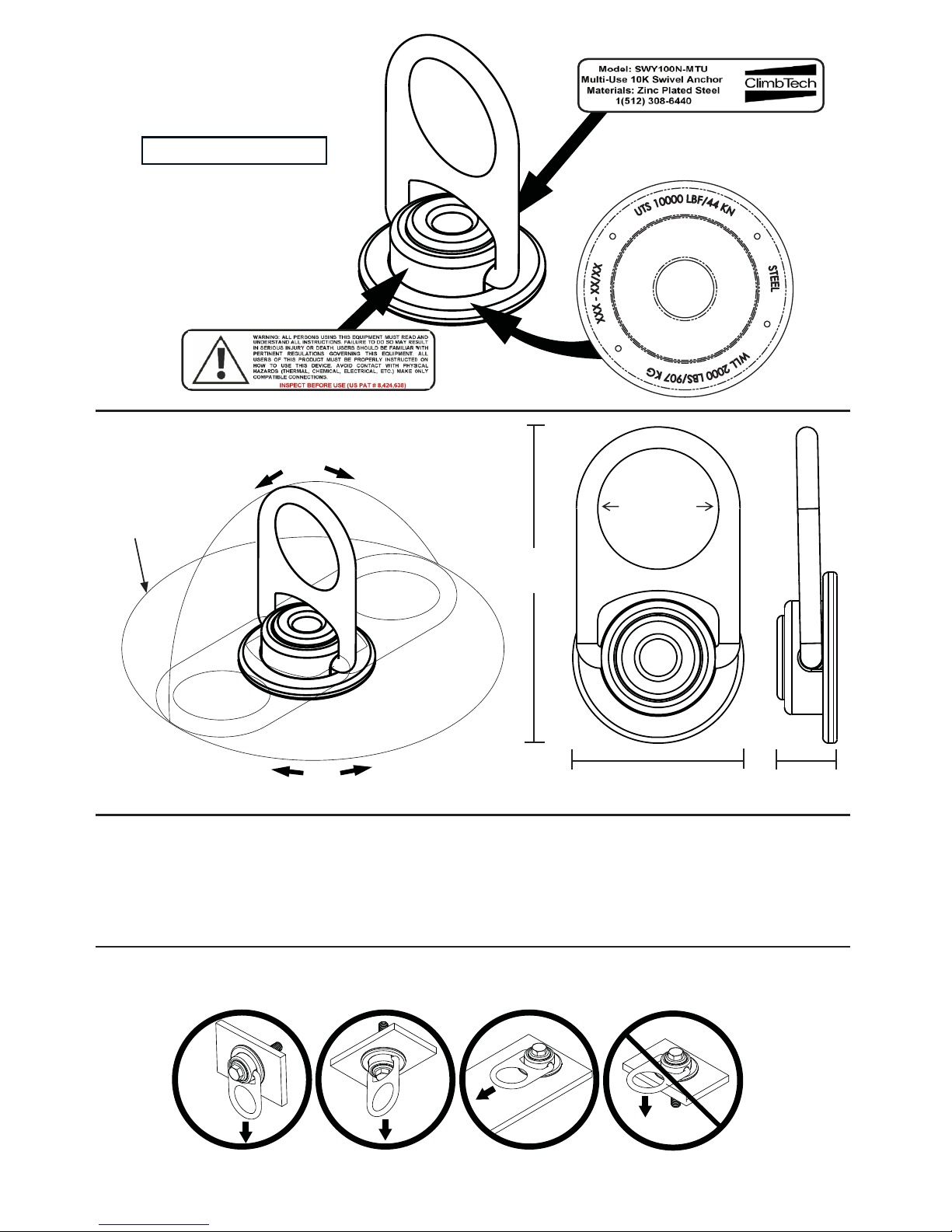
LABEL LOCATIONS
8”ø
(203.2mm)
180°
360°
5.5”
(139.7mm)
2.25”ø
(57.15mm)
3”
(76.2mm)
1”
(25.4mm)
Tensile Strength (UTS): 10,000-lbf (44kN)
Working Load: 2,000-lbs (907kg)
Weight: 1.2-lbs (544.3g)
Materials: Zinc Plated Steel
LOADING CONDITIONS DIAGRAM
ACCEPTABLE ACCEPTABLE IMPROPER
ACCEPTABLE
Page 4
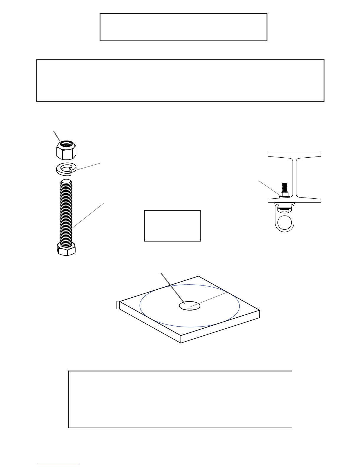
STEEL MOUNTING
Torque Range:
75 to 90 ft-lbs
(100-120Nm)
* Use tapered washer with I-beams
that have tapered anges.
.75”
(6mm)
min
drill 5/8” (16mm)Ø
3”(76mm)
min from any edge
Lock Nut
5/8” Lock
Washer
5/8”-11x4”
Hex Bolt *
5/8”-11
* For steel applications a grade 5, grade 8 (or equivalent) bolt no
shorter than 4” (100mm) with a locking nut and washer must be
used. Swivel anchor must be ush with steel surface. A 16mm
bolt of equal strength may be used in place of a 5/8”-11
for metric applications.
1. Use a proper drill and bit for steel.
2. Drill a 5/8” (16mm) hole no less than .75” (6mm) deep 3” (76mm) away from any edge.
3. Hole must be straight and perpendicular to surface.
4. Hole must be free of debris.
Page 5

CONCRETE MOUNTING
1. Use a proper drill and bit for concrete (SDS drill bit).
2. Drill a .75” (19mm) hole no less than 5” (114mm) deep 9” (229mm) away from any edge.
3. Hole must be straight & perpendicular to surface.
4. Hole must be free of debris
5. Concrete strength must be at least 3000psi (20.7MPa) and no less than 7” (178mm)
thick.
9”
(
22
9m
m
)
drill
3/4” (19mm)
Ø
m
i
n
f
ro
m
a
ny
e
d
g
e
7”
(178mm)
min
Embedment Depth
4.5” min (114mm)
Torque:
110 ft-lbs (149Nm)
Page 6

BACK PLATE MOUNTING
WELD ON MOUNTING
* Welding procedure must be approved by an engineer or other
qualied person to be compatible with any and all structural &
operational characteristics of the selected installation location.
Torque Range:
to be determined
by an engineer or
qualied person.
Back Plate to be used with 5/8” (16mm)
bolts or all thread. Drill hole perpendicular
into surface so bolt can pass freely through
the substrate. Nut must be fully threaded
on the bolt to insure maximum strength
ratings and integrity of anchor.
* Bolt or All-thread and nut not included with Back Plate.
Torque Range:
75 to 90 ft-lbs
(100-120Nm)
Grade - 5 or 8 bolt
5/8”-11 x 1-3/4”
Weld Puck
(AISI 1018)
3/8” min
(9.5mm)
* Weld
Internal Tooth Lock Washer
Page 7

STRAIGHT LOOP INSERT
See Straight Loop Insert Manual for anchorage casting instructions.
Internal Tooth
Lock Washer
WARNING: Do not install if insert was knocked over during installation.
Mega Swivel must mount ush to surface when fastened with the
proper torque.
Torque Range:
70 to 80 ft-lbs
Orange
Housing
Plastic Bolt to
be removed
5/8”-11x3.25”
Hex Cap Bolt *
Note: Ensure internal threads are
thoroughly coated with NLGI2
multi-purpose lithium grease
(meeting Sinopec specification
Q/SH303 242-2007 or equivalent).
1. Strip decking to expose the Straight Loop Insert.
2. Ensure that anchorage was properly installed. Orange indicator should be ush with
concrete surface, and at least 9” from any edge or corner. Concrete should be at least
6” thick and cured to a minimum of 3000 psi.
3. Remove plastic bolt and o-ring using 1/2” allen wrench.
4. Save plastic bolt and o-ring to re-insert into Straight Loop Insert when not in use.
5. Insert bolt and washer through Mega Swivel and into the threaded
hole of the Straight Loop Insert.
6. To fasten Mega Swivel, tighten bolt* to 70-80 ft-lbs using torque wrench.
Page 8

+
CONCRETE METALACCESSORIES
KIT CONTENTS
PART NUMBER
+
SWY1SBA-400-CTS
(Steel Mounting Hardware Kit)
SWY100S-MTU-CTS
(Swivel with Steel Mounting kit)
SWY1CSA-55P-CTS
(Concrete Hardware Kit)
SWY100C-MTU-CTS
(Swivel with Concrete Mounting Kit)
SWP100N-KIT-CTS
(Weld-on Mounting Kit)
SWX100N-QPQ-CTS
(Backing Plate Only)
+
SWY100P-MTU-CTS
(Swivel with Straight Loop Insert
Mounting kit)
SWY1PBA-325-CTS
(Straight Loop Insert Mounting Kit)
+
SL4625C-ZNO-CTS
(Straight Loop Insert)
Page 9

Part Number Comments Inspector Name
Date
MODEL NUMBER:
DATE OF MANUFACTURE:
Inspection:
Ocial periodic inspection must be made at least semiannually. The inspection must be performed by a
qualied person other than the intended user. If severe weather or conditions exist then inspections must be
carried out more frequently. All inspection results must be logged in the space provided above.
1. Inspect swivel to make sure it is ush with mounting surface.
2. Make sure all labeling is axed to the unit.
3. Make sure the unit can rotate 360° and D-ring can ip from side to side.
4. When reusing a previously drilled hole, inspect for for debris or wallowing.
5. Record inspection results in the space provide above.
*If any damage that could aect the strength or operation of the device, or unsafe conditions are found, proper disposal is required. The anchorage connector must be rendered
unusable and then properly discarded.
MAINTENANCE, CLEANING AND STORAGE
Cleaning periodically will prolong the life and proper functioning of the product. The frequency
of cleaning should be determined by inspection and by severity of the environment. Clean with
compressed air and/or a sti brush using plain water or a mild soap and water solution. Do not use
any corrosive chemicals that could damage the product. Wipe all surfaces with a clean, dry cloth
and hang to dry, or use compressed air. When not in use, store anchorage connectors in a cool, dry,
clean environment, out of direct sunlight and free of corrosive or other degrading elements.
INSPECTION AND MAINTENANCE LOG
Page 10

NOTES
Page 11

NOTES
Page 12

ClimbTech, LLC.
7303 Burleson Rd. Suite 901 Austin, TX 78744
1(512) 308-6440 / www.climbtech.com
Product Warranty, Limited Remedy and Limitation of Liability
WARRANTY: THE FOLLOWING IS MADE IN LIEU OF ALL WARRANTIES OR CONDITIONS, EXPRESS OR
IMPLIED, INCLUDING THE IMPLIED WARRANTIES OR CONDITIONS OF MERCHANTABILITY OR FITNESS
FOR A PARTICULAR PURPOSE. Equipment oered by ClimbTech is warranted against factory defects in
workmanship and materials for a period of one year from date of purchase or rst use by the original owner.
LIMITED REMEDY: Upon notice in writing, ClimbTech will repair or replace all defective items at ClimbTech’s
sole discretion. ClimbTech reserves the right to require that the defective item be returned to its plant for
inspection before determining the appropriate course action. Warranty does not cover equipment damage
resulting from wear, abuse, damage in transit, failure to maintain the product or other damage beyond the
control of ClimbTech. ClimbTech shall be the sole judge of product condition and warranty options. This
warranty applies only to original purchaser and is the only warranty applicable to this product. Please contact
ClimbTech technical service department for assistance.
LIMITATION OF LIABILITY: IN NO EVENT WILL CLIMBTECH BE LIABLE FOR ANY INDIRECT, INCIDENTAL,
SPECIAL OR CONSEQUENTIAL DAMAGES INCLUDING, BUT NOT LIMITED TO LOSS OF PROFITS, IN ANY
WAY RELATED TO THE PRODUCTS REGARDLESS OF THE LEGAL THEORY ASSERTED.
For more information:
 Loading...