

Page 1
TThhee W
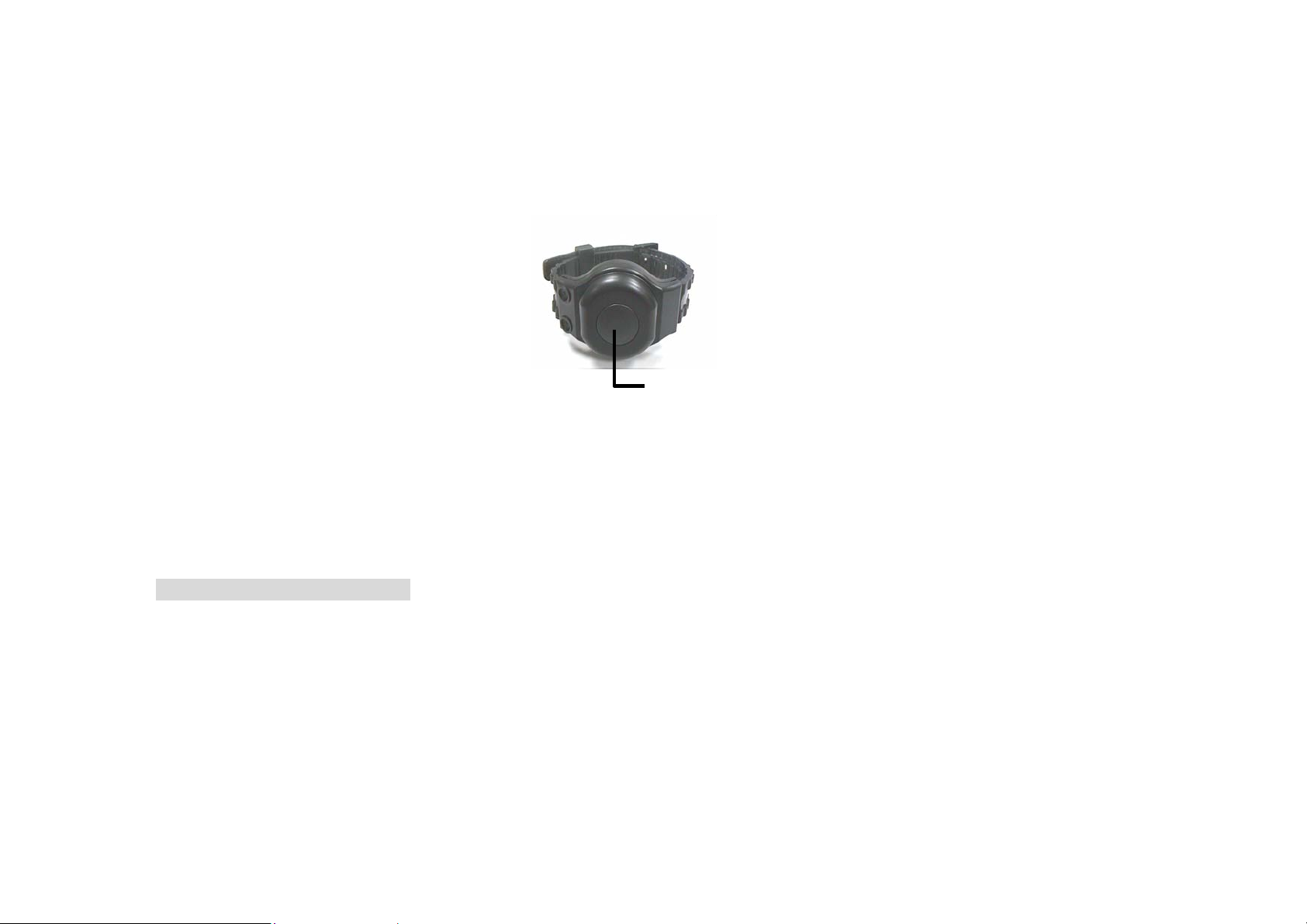
The Wrist Transmitter (WT-GS) is designed sized and looks like a wristwatch, an d is to be worn on the wrist at all times. The WT-GS brings help to your door
when you need it most by pressing the button, which is on the top of it. The design ensures triggering the alarm is easily done while cautious handling to
prevent false alarm is unnecessary.
Wrriisstt TTrraannss
miitttteerr ((
m
WTT--
W
GSS))
G
AAccttiivvee BBuuttttoonn
Pressing the Active Button for more than 1 sec will activate the Main Unit, causing it to dial emergency call or alarm.
When the Main Unit receives the alarm signal and is being activated, you can stop the activity if desired by pressing
this button for more than 8 sec.
TThhee WWrriisstt TTrraannssmmiitttteerr’’ss IIDD CCooddee
Every Wrist Transmitter has a unique numeric code called “ID code”. The ID code enables the Main Unit to identify the signal is transmitted from the
Wrist Transmitter. At the same time, it also prevents interference from outside sources.
BBaatttteerryy LLiiffee
The Wrist Transmitter use one 3V 950mAh Lithium battery as its power source. The battery can last for 10 years.
AApppplliiccaattiioonn
In CTC-740/CTC-790 System
CTC-740/CTC-790 Main Unit uses “Learning” technology to set the Transmitter’s ID code and up to six ID codes can be recorded by the Main Units.
During installation, the ID code of the W rist Transmitter should be learned by the Main Unit so that the Wrist Transmitter can communicate with the Main
Unit.
Active Button
Learning the Wrist Transmitter’s ID code:
Step 1. Put the Main Unit in Learn mode.
Step 2. Press the Active Button for more than 1 sec.
Step 3. If the Main Unit receive the signal, it will sound a long beep indicating Learning is successful.
Step 4. Put the Main Unit back to Normal operation mode.
Page 2

In CTC-730/750/850/830/870/840/880/815 System
This category of Main Units also use “Learning” technology to set the Transmitter’s ID code. However, only one ID code (System ID code) is allowed in
one system.
Case 1. If the WTR is the only device used in the system
Follow the same procedures as in the CTC-740/790 system described above for the Main Unit to program the ID code.
Case 2. If there are other devices also included in the system
All the devices in the system should have same ID code setting.
For any other devices except the WTR, the ID code is set by positioning the eight switches on the “ID Code Switch Block”.
In order to enable you to set the ID code for any device to the same setting as on the WTR, a sticker showing the sketch of correct switch positions which
represent the ID code of the WTR is stuck on the rear side of the WTR.
You have to position the switches on the “ID Code Switch Block” on each device according to the switch position sketch. Then follow the same
procedures as in the CTC-740/790 system described above for the Main Unit to program the ID code of the WTR.
Step 1. Locate the sticker on the rear side of the WTR and observe the switch positions closely.
Step 2. Position the eight switches on the “ID Code Switch Block” on each device according to the switch position sketch.
Step 3. Put the Main Unit in Learn mode.
Step 4. Press the Active Button on the WTR for more than 1 sec.
Step 5. If the Main Unit receives the signal, it will sound a long beep indicating Learning is successful.
Step 6. Put the Main Unit back to Normal operation mode.
In CTC-500/600/760 system
For this category of Main Units, an “ID Code switch Block “is also included on the Main Unit and all of the eight switch settings should be set exactly the
same as those on each device.
Please refer to the information described in the case 2 of the prior category to set the ID code on each device including the Main Unit according to the
switch positions sketch showing on the sticker on the rear side of the WTR.
Page 3

FEDERAL COMMUNICATIONS COMMISSION
This device complies with Part 15 of the FCC Rules. Operation is subject to the following two con ditions:(1) this device may not cause harmful inte rference, and
(2) this device must accept any interference received, including interference that may cause undesired operation.
Changes or modifications not expressly approved by the party responsible for compliance could void the user‘s authority to operate the equipment.
NOTE
This equipment has been tested and found to comply with the limits for a Class B digital device, pursuant to Part 15 of the FCC Rules. These limits are
designed to provide reasonable protection against harmful interference in a residential installation. This equipment generates, uses and can radiated radio
frequency energy and, if not installed and used in a ccordance with the inst ructions, may cau se harmful interfere nce to radio communications. However, there is
no guarantee that interference will not occur in a particular installation If this equipment does cause harmful interference to radio or television reception, which
can be determined by turning the equipment off and on, the user is encouraged to try to correct the interference by one or more of the following measures:
-Reorient or relocate the receiving antenna.
-Increase the separation between the equipment and receiver.
-Connect the equipment into an outlet on a circuit different from that to which the receiver is connected.
-Consult the dealer or an experienced radio/TV technician for help.
Note:
This device and its antenna(s) used for this transmitter must not be co-located or operating in conjunction with any other antenna or transmitter.
 Loading...