

Page 1
1
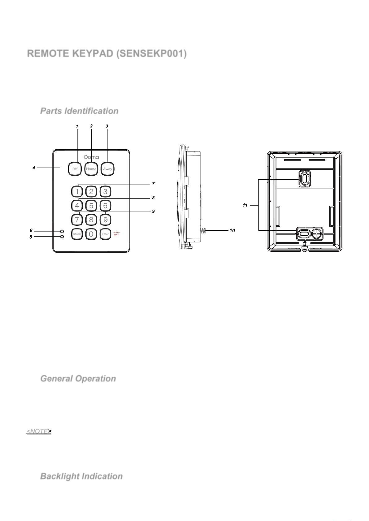
1. Off Key/LED
2. Home Key/LED
3. Away Key/LED
4. Buzzer
5. Fault LED (Orange LED)
6. Power LED (Green LED)
7. Panic Alarm
- press both 1 and 3 to trigger Panic Alarm
8. Fire Alarm
- press both 4 and 6 to trigger Fire Alarm
9. Medical Alarm
- press both 7 and 9 to trigger Medical alarm
10. Tamper Switch
11. Mounting Holes
Trade name: Ooma
Model name: SENSEKP001
Manufacturer: Climax Technology Co Ltd
REMOTE KEYPAD (SENSEKP001)
SENSEKP001 is a smart wireless remote keypad that includes a DECT ULE transceiver for reliable system operation.
It uses smart message control, which verifies that all messages are successfully transmitted. The keypad also features a power
conservation function that consumes power only when in operation.
No. 258, Sinhu 2nd Rd., Neihu District, Taipei
City 114 Taiwan
Parts Identification
General Operation
Press any key for one second to send a short key value.
Press any key for more than 3 seconds to send a long key value.
Panic Alarm — Press 1 key + 3 key at the same time.
<NOTE>
Backlight Indication
Fire Alarm — Press 4 key + 6 key at the same time.
Medical Alarm — Press 7 key + 9 key at the same time.
A short beep will sound when a key is pressed. A long beep will sound when a key is pressed and held for more than 3
seconds.
Each valid key press will be transmitted to the Control Panel as an event. The Keypad will wait for 30 seconds to
receive response from the Control Panel.
After battery is inserted, the backlight will flash once to indicate that Keypad is ready for operation.
Page 2

2
The backlight will turn on for 10 sec when any key (except Off/Home/Away key) is pressed. When the Off/Home/Away
key is pressed, the backlight remains off.
Power
Remote keypad uses one CR123 3V Lithium battery as its power source.
Remote keypad can also detect the battery status. If the battery voltage is low, the Low battery signal will be sent to the
Control Panel for displaying the status accordingly.
Before shipment, the battery is pre-installed by the factory.
When changing battery, press any key a couple times to discharge before inserting new battery.
<WARNING>
The polarity of the battery must be observed.
Only use specified battery with the keypad. Improper use or handling of lithium battery may result in heat
generation, fire or explosion, which may lead to personal injuries.
Dispose of used battery according to the instructions.
Operating Temperature & Humidity
Operating Temperature: -10°C ~ 50°C
Humidity: Up to 85% relative humidity @23°C
Tamper Protection
The keypad is protected against any attempt to open the lid or to detach keypad from its mounting surface.
Tamper protection is disabled when the keypad is in Test Mode.
Getting Started
A. The Keypad has never been learned into a Control Panel (First Time Learning)
Step 1. Put the Control panel into learning mode.
Step 2. Power on the keypad by removing the battery insulator, the Remote keypad will automatically send a learn
code to the Control Panel.
Step 3. During learning process, the power LED will flash for 10 times.
Step 4. If the Control Panel receives the learning code, it will display the info accordingly. Refer to the operation
manual of your Control Panel to complete the learn-in process.
Step 5. The Keypad will emit 3 beeps when learning is successful.
B. The Keypad has been previously learned into a Control Panel (Re-learn into a new Control Panel)
Step 1. Put the Control panel into learning mode.
Step 2. Put the Keypad into test mode. (Refer to Test Mode section.)
Press “Cancel” key and 7 to send a learning code to the Control Panel. Remote keypad will sound a long beep.
Step 3. During learning process, the power LED will flash for 10 times.
Step 4. If the Control Panel receives the learning code, it will display the info accordingly. Refer to the operation
manual of your Control Panel to complete the learn-in process.
Step 5. The Keypad will emit 3 beeps when learning is successful.
After the Remote keypad is learnt-in, press any key under normal operation mode to send a key value to the Control
Panel to confirm this location is within the signal range of the Control Panel. (If the keypad is still in test mode, please
leave test mode by pressing the Away key twice.)
When you are satisfied that the Remote keypad works in the chosen location, you can proceed with mounting the
Remote keypad following the steps described below (p
lease refer to “Mounting Remote keypad” for details).
Test Mode
To enter test mode:
1) Press and hold the “Enter” key while powering on the remote keypad by inserting the CR123 3V Lithium battery.
Keep holding the “Enter” key and don’t release it until the backlight turns on with two beeps.
2) Within 30 seconds put remote keypad in Test mode by entering keypad PIN code (default: 0000), then press the
“Cancel” key.
3) The three Off/Home/Away LEDs will turn on along with a long beep.
<NOTE>
If keypad PIN code is entered incorrectly, Fault LED (Orange LED) will flash 4 times along with 4 beeps.
Page 3
3
Test Mode Function:
Unit
Definition
Reference
Unit 0
Device Management Service
Table 2
Unit 1
Key (Each Key is defined for Short Key Value, Long Key Value, and Dual Key
Value.)
Table 3,4,5,6
Unit 2
Power LED (Green)
Table 7
Unit 3
Fault LED (Orange)
Table 8
Unit 4
Buzzle
Table 9
Unit 5
Off LED
Table 10
Unit 6
Home LED
Table 11
Unit 7
Away LED
Table 12
Interface
UID
M/O
Base
Keypad
Device Management Service
0x0001
M
Client Side
Server Side
Device Information Service
(Annex A)
0x0005
M
Client Side
Server Side
Attribute Reporting Service
0x0006
M
Client Side
Server Side
1) Press the “Cancel” key and then 6 key to Edit Keypad Pin Code.
Enter Old Keypad Pin Code and then press the “Cancel” key. A long beep will sound.
Enter New a new 4-digit Keypad Pin Code and then press the “Enter” key. A long beep will sound.
<NOTE>
If the Old Keypad Pin Code is entered incorrectly, the keypad will emit 4 beeps to indicate error.
If more or less than 4 digits are entered for the New Keypad Pin Code, the keypad will also emit 4 beeps
to indicate error.
2) Press the “Cancel” key then 7 key to send the learning code.
3) Press the “Away” key twice to leave Test mode.
<NOTE>
The Remote keypad will automatically exit Test mode after 5 minutes of inactivity and return to Stand-by
mode. All the LEDs will turn off and the Keypad will emit one long beep.
Keep Alive
The Keypad transmits keep Alive signal regularly every 120 minutes.
Reset PIN Code to Default
Step 1 Remove the batteries and release the tamper.
Step 2 Press & hold 3 key while inserting the battery back.
Step 3 Continue pressing 3 key until keypad emit 3 beeps to indicate successful reset.
Step 4 Release 3 key, the reset process is complete.
After reset, PIN code reverts to factory default values, 0000.
Mounting Remote Keypad
To mount the remote keypad:
I. Remove the front cover.
II. Using the 2 mounting holes of the back cover as a template, mark off the positions in the most appropriate place.
III. Insert the wall plugs if fixing into plaster or brick surface.
IV. Screw the Remote keypad onto the wall plugs.
V. Replace the front cover.
Unit Definition
Table1- Unit definition
ULE Information
Home Control Profile: Simple Keypad
Unit ID: 0
Unit Type: Device Management (0x0001)
Table 2
Page 4

4
Power Service
0x0110
O
Client Side
Server Side
Keep Alive Service
O
Client Side
Server Side
Tamper
O
Client Side
Server Side
SUOTA Service
0x0400
O
Server Side
Client Side
Interface
UID
M/O
Base
Keypad
Simple Keypad Interface
(Annex B)
0x0203
M
Client Side
Server Side
Alert Interface
(Annex C)
0x0100
O
Client Side
Server Side
Key
Short Key Value
0
0x00000030 ( U32)
1
0x00000031 ( U32)
2
0x00000032 ( U32)
3
4
5
6
7
8
9
Cancel
Enter
Off
Home
Away
Key
Long Key Value
0
0x80000030 ( U32)
1
0x80000031 ( U32)
2
0x80000032 ( U32)
3
0x80000033 ( U32)
4
0x80000034 ( U32)
5
0x80000035 ( U32)
6
0x80000036 ( U32)
7
0x80000037 ( U32)
8
0x80000038 ( U32)
9
0x80000039 ( U32)
Cancel
0x8000002A ( U32)
Enter
0x80000023 ( U32)
Off
0x8001F512 ( U32)
Home
0x80002302 ( U32)
Away
0x8001F513 ( U32)
Key
Dual Key Value
1 + 3 (Panic Alarm)
0x00000001 ( U32) (Active)
0x00000000 ( U32) (Restore)
4 + 6 (Fire Alarm)
0x00000002 ( U32) (Active)
0x00000000 ( U32) (Restore)
7 + 9 (Medical Alarm)
0x00000004 ( U32) (Active)
0x00000000 ( U32) (Restore)
0x0115
0x0101
Unit ID: 1
Unit Type: Simple Keypad (0x0118)
Table 3
a. Key Value (Short Key) [Simple Keypad Interface]
Table 4 - Short Key
0x00000033 ( U32)
0x00000034 ( U32)
0x00000035 ( U32)
0x00000036 ( U32)
0x00000037 ( U32)
0x00000038 ( U32)
0x00000039 ( U32)
0x0000002A ( U32)
0x00000023 ( U32)
0x0001F512 ( U32)
0x00002302 ( U32)
0x0001F513 ( U32)
b. Key Value (Long Key) (The key has been pressed more than 3 sec.) [Simple Keypad Interface]
Table 5 - Long Key
c. Key Value (Dual Key)[ Alert Interface]
Table 6 - Dual Key
Unit ID: 2
Unit Type: Simple Led (0x0113), Power Led (Green)
Table 7 - Power Led
Page 5

5
Interface
UID
M/O
Base
Keypad
Simple Visual Control Interface
(Annex D)
M
Client Side
Server Side
Interface
UID
M/O
Base
Keypad
Simple Visual Control Interface
(Annex D)
0x0305
M
Client Side
Server Side
Interface
UID
M/O
Base
Keypad
Simple Visual Control Interface
(Annex D)
0x0305
M
Client Side
Server Side
Interface
M/O
Base
Keypad
Simple Visual Control Interface
(Annex D)
M
Client Side
Server Side
Interface
M/O
Base
Keypad
Simple Visual Control Interface
(Annex D)
M
Client Side
Server Side
Interface
UID
M/O
Base
Keypad
Simple Visual Control Interface
(Annex D)
0x0305
M
Client Side
Server Side
Identifier
Name
Content
Access
0x01
HF core Release
02
Read
0x02
Profile Release
01
Read
0x03
Interface Release
01
Read
0x04
Paging Caps
00
Read
0x05
Min Sleep Time
00000000
Read
0x06
Actual Response Time
00000000
Read
0x07
Application Version
3
Read
0x08
Hardware Version
-
Read
0x09
EMC
0FEB
Read
0x0A
IPUI
0298B000F6
Read
0x0B
Manufacture
-
Read
0x0C
Location
Living Room
Read/Write
0x0D
Device Enable
01
Read/Write
0x0E
Friendly Name
-
Read/Write
0x0F
Device UID
(None)
Read
0x10
Serial
abcd
Read
0x0305
Unit ID: 3
Unit Type: Simple Led (0x0113), Fault Led (Orange)
Table 8 - Fault Led
Unit ID: 4
Unit Type: Simple Led (0x0113), Buzzle
Table 9 - Buzzle
Unit ID: 5
Unit Type: Simple Led (0x0113), OFF Led
Table 10 - OFF Led
UID
0x0305
Unit ID: 6
Unit Type: Simple Led (0x0113), Home Led
Table 11 - Home Led
Unit ID: 7
Unit Type: Simple Led (0x0113), Away Led
Table 12 - Away Led
Annex A: Device Information Services
Table 13 - Device Information Interface: Attributes
UID
0x0305
Annex B: Simple Keypad Interface
1. Server Attributes: None
2. Client Attributes: None
3. Server to Client Commands:
Page 6

6
Table 14 - Simple Keypad commands
Command ID
Server Role
Response
0x01
KeyPressed
M M O
Attribute ID
Attribute
Name
Attribute
Type
Attribute Values
Attribute
Access
M/O
0x01
State
U32
(bitmask)
0x00000000 0xFFFFFFFF
Read Only
M
0x02
Enable
U32
(bitmask)
0x00000000 0xFFFFFFFF
Read / Write
M
Command
Server Role
Response
Status
M
N/A
Command ID
Server Role
Response
0x01
M
O
0x02
M O 0x03
O
O
Command Name Client Role
4. Client to Server Commands: None
Annex C: Alert Interface
1. Server Attributes
Table 15 - Alert Interface Server, Attributes
2. Client Attributes: None
3. Server to Client Commands
Table 16 - Implementation status of Alert Interface Server commands.
Client Role
M
4. Client to Server Commands: None
Annex D: Simple Visual Control Interface
1. Server Attributes: None
2. Client Attributes: None
3. Server to Client Commands: None
4. Client to Server Commands
Table 17 - Implementation status of Simple Visual Control Client commands
Command Client Role
ON O
OFF O
Blink O
Reference:
[1] HF-Profile-Version_1.4.0.pdf
[2] HF-Service-Version_2.0.0.pdf
[3] HF-Interface-Version_1.4.0.pdf
Page 7

Federal Communicatio
n Commission Interference Statement
This equipment has been tested and found to comply with the limits for a Class B digital device, pursuant
to Part 15 of the FCC Rules. These limits are designed to provide reasonable protection against harmful
interference in a residential installation.
This equipment generates, uses and can radiate radio frequency energy and, if not installed and used in
accordance with the instructions, may cause harmful interference to radio communications. However,
there is no guarantee that interference will not occur in a particular installation. If this equipment does
cause harmful interference to radio or television reception, which can be determined by turning the
equipment off and on, the user is encouraged to try to correct the interference by one of the following
measures:
. Reorient or relocate the receiving antenna.
. Increase the separation between the equipment and receiver.
. Connect the equipment into an outlet on a circuit different from that to which the receiver is connected.
. Consult the dealer or an experienced radio/TV technician for help.
FCC Caution: To assure continued compliance, any changes or modifications not expressly approved by
the party responsible for compliance could void the user's authority to operate this equipment. (Example use only shielded interface cables when connecting to computer or peripheral devices).
This device complies with Part 15 of the FCC Rules. Operation is subject to the following two conditions:
(1) This device may not cause harmful interference, and (2) This device must accept any interference
received, including interference that may cause undesired operation.
FCC E
xposure to Radio Frequency (RF) Signals
This equipment must be installed and operated in accordance with provide instructions and the antenna used for this
transmitter must be installed to provide a seperation distance of at least 20 cm from all persons.
This equipment complies with FCC RF radiation exposure limits set forth for an uncontrolled
environment.
This transmitter must not be co-located or operating in conjunction with any other antenna or transmitter.
7
 Loading...