

Page 1
August15,2013
Page 2

Table of Contents
1. INTRODUCTION..................................................................................................................1
1.1. THE MX MEDICAL AND INTRUSION ALARM SERIES.............................................................1
1.2. WHAT’S IN THE BOX.............................................................................................................. 2
2. SYSTEM OVERVIEW..........................................................................................................3
2.1. IDENTIFYING THE PARTS .......................................................................................................3
2.2. POWER SUPPLY ....................................................................................................................7
3. INSTALLING MX..................................................................................................................8
4. PROGRAMMING MX...........................................................................................................9
4.1. PC PROGRAMMING...............................................................................................................9
4.1.1. Installing USB Driver...................................................................................................9
4.1.2. PC Programming Tool..............................................................................................16
4.2. WEB PROGRAMMING ..........................................................................................................47
4.2.1. Installing the Finder Software ................................................................................47
4.2.2. Programming MX....................................................................................................... 50
4.3. SMS PROGRAMMING..........................................................................................................69
5. DEVICE MANAGEMENT...................................................................................................74
5.1. LEARNING IN PENDANT #1, PENDANT #2 AND OTHER DEVICES.......................................75
5.1.1. Learning in Pendant #1............................................................................................75
5.1.2. Learning in Pendant #2............................................................................................77
5.1.3. Learning in Other Devices....................................................................................... 79
5.2. REMOVING PENDANT #1, PENDANT #2 A ND OTHER DEVICES..........................................80
6. OPERA TION.......................................................................................................................81
6.1. CONTROL PANEL................................................................................................................. 81
6.1.1. Idle Mode...................................................................................................................... 81
6.1.1.1. Answering Incoming Calls........................................................................................... 81
6.1.1.2. Non-Emergency Calls ................................................................................................... 82
6.1.1.3. AC Power Checkup........................................................................................................83
6.1.1.4. Control Panel Low on Battery.....................................................................................84
6.1.1.5. Control Panel’s Battery Disconnected...................................................................... 84
6.1.1.6. Devices Low on Battery................................................................................................84
6.1.1.7. Automatic Check-In Reports....................................................................................... 85
6.1.1.8. Inactivity Timer............................................................................................................... 85
6.1.2. Alarm Activation......................................................................................................... 88
Page 3

6.1.3. Arming/Disarming the System...............................................................................97
6.1.4. Voice Prompts............................................................................................................99
6.1.5. Walk Test (Range Test)...........................................................................................100
6.1.6. Factory Reset............................................................................................................ 100
7. APPENDIX .......................................................................................................................101
7.1. CONTACT ID COMMUNICATIONS PROTOCOL AND FORMAT .............................................101
7.1.1. Handshake Tones.......................................................................................................101
7.1.2. Placement .....................................................................................................................101
7.1.3. Composition.................................................................................................................101
7.1.4. Message Blocks ..........................................................................................................102
7.1.5. Placement .....................................................................................................................102
7.1.6. Message Composition............................................................................................... 102
7.1.7. Data Tones....................................................................................................................102
7.1.8. Kiss off (Acknowledgement) Tones .......................................................................103
7.1.9. Contact ID Event Codes............................................................................................103
7.2. SIA DIGITAL COMMUNICATION STANDARD.......................................................................105
7.3. SCANCOM EVENT CODES.................................................................................................106
7.4. TUNSTALL TTNEW EVENT CODES..................................................................................107
7.5. CLIMAX CPC DIALECT EVENT CODES.............................................................................108
7.6. FRANKLIN EVENT CODES................................................................................................. 110
Page 4

1. Introduction
1.1. The MX Medical and Intrusion Alarm Series
Climax’s MX Medical and Intrusion Alarm Series marks a watershed in the
evolvement of medical alarm systems. One of the first of Climax’s wireless
medical alarms to be integrated with an intrusion alarm system, the MX Series
not only provides thorough care for your loved ones at home but also protects
your house and property when you are away. Incorporating various
cutting-edge telecare technologies, the MX Series features a new,
user-friendly three-button design that fully utilizes the flexibility and versatility
of the system. The user can summon emergency help by one press on the red
button and arm his house by one press on the yellow button. Events
happening at home will be reported to the monitoring center via the Contact ID,
Tunstall (TT New), Climax CPC Dialect or 4+2 Franklin communication
protocols. Living under protection and going in and out in peace have never
been easier.
MX Models
Model Alarmcommunicationspath(s) CompatibilitywithEZ‐1orEZ‐2
MX‐2 PSTN EZ‐1orEZ‐2
MX‐3 GSM/3G EZ‐1
MX‐6 EthernetandPSTN EZ‐1orEZ‐2
MX‐8 EthernetandGSM/3G EZ‐1
1
Page 5

1.2. What’s in the Box
Your MX sample package includes the following items:
z Control Panel
z AC adaptor for the Control Panel
z USB cable
z CD-ROM containing
- MX Installation and Operation Guide
- USB Driver for MX
- PC Programming Tool
- The Finder software (MX-6 and MX-8 only)
2
Page 6
2. System Overview
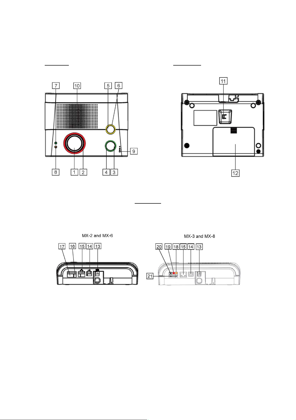
2.1. Identifying the Parts
Top View Back View
Side View
3
Page 7

Control Panel Definitions
Button/LED/Component
1 Red Help Button
2 Red Backlight
3 Green Reset Button
4 Green Backlight
Behavior Function/Indication
Pressed in idle/normal mode To summon emergency help
Pressed once in learning
mode
Pressed for 3 seconds in
learning mode
Dimly lit Idle/normal mode
Blinking 1. Guard time
Brightly illuminating 1. Busy with alarm
Pressed in idle/normal mode 1. To reset the inactivity
Pressed once before the
Control Panel dials out for
alarm reporting
Pressed once during or at
the end of a two-way
communication
Pressed for 3 seconds in
idle/normal mode
Pressed once in learning
mode
On 1. After a non-emergency
Off 1. Idle mode
To select Pendant #2
To delete a selected pendant
2. Pauses during retries of
alarm reporting
reporting
2. After an alarm report
receives a callback and
until the call is hung up
timer
2. For the Control Panel to
report all the fault
problems it is
experiencing via voice
prompts
To cancel the alarm reporting
To terminate the two-way
communication
To make a non-emergency
call
To select Pendant #1
call is dialed out and until
the call ends
2. Busy with status
reporting
3. When two-way
communication is
opened after an
incoming call is picked
up and until the call ends
2. Pauses during retries of
status reporting
4
Page 8

Button/LED/Component
4 Green Backlight
5 Yellow Button can
serve as:
- Inactivity Button
- Check-in/out Button
- Away/Home Button
- Non-Emergency Call
Button
- Security Button
6 Orange Backlight
7 Green LED (Volume
Switch)
8 Orange LED (Volume
Switch)
9 Microphone
Blinking (on MX-2 and MX-6
only)
Pressed once when serving
as an inactivity, check-in/out
or away/home button
Pressed once when serving
as a security button
Pressed once when serving
as a non-emergency button
Pressed for 3 seconds To enter learning mode
Pressed once in learning
mode
Steady on The inactivity timer is on.
Off The inactivity timer is off.
Blinking The Control Panel is in
Steady on AC power is on.
Blinking twice every second AC power fails.
Pressed once To increase the speaker
Pressed once To lower the speaker volume
Blinking every 3 seconds The Control Panel is low on
Blinking twice every second A device is low on battery or
Off All the conditions signified by
Behavior Function/Indication
The Control Panel has a
phone line fault.
To toggle on/off the inactivity
timer
To arm the system
To make a non-emergency
call
To exit learning mode
learning mode.
volume
battery or is having an
overvoltage condition.
is tampered with.
this blinking orange LED
have been removed.
10 Speaker
11 Battery Switch On/off
12 EZ-1/EZ-2 Lid
13 DC Jack Connects to a DC 12V 2A switching power adapter.
14 USB Port
15 Ethernet Port (On MX-6 and MX-8 only)
16 Phone Jack Marked Connects to a phone line from the wall.
17 Phone Jack Marked Connects to a telephone unit.
5
Page 9

Button/LED/Component
18 GPRS/GSM or 3G Fault
Indicator (orange)
Behavior Function/Indication
On Failed registration
>
<<NNOOTTEE>
) Registration will fail
when an AC power
failure occurs.
Off Successful registration
19 GPRS/GSM or 3G
Status Indicator (red )
20 GPRS/GSM or 3G Reset
Button
21 SIM Card Base Insert your SIM card in this slot.
Blinking
Pressed for one second
When the GPRS/GSM or 3G
module operates normally
To reset GPRS/GSM or 3G
6
Page 10

2.2. Power Supply
z Plug the AC power adapter into the Control Panel’s DC jack and connect
to the mains power. Make sure that you use an adapter with the
appropriate AC voltage rating to prevent component damage. An AC-DC
12V/2A switching power adapter is generally used to power the standard
version of the Control Panel.
z In addition to the AC power adapter, a rechargeable battery is installed
inside the Control Panel to serve as a backup in case of a power failure.
z During normal operation, the AC power adapter is used to supply power to
the Control Panel and at the same time recharge the battery. It takes
approximately 72 hours to fully charge the battery.
z If the battery switch is set as OFF, the battery will not be charged when
AC power is connected and nor will it serve as a backup power source
when AC power is missing. You need to switch the battery to ON for it to
be charged when AC power is connected and serve as a backup power
source when AC power is missing.
7
Page 11

3. Installing MX
Step 1. Choose a suitable location for the Control Panel. The Control Panel
requires the mains power and PSTN (MX-2 and MX-6), GSM/3G
(MX-3 and MX-8) and/or Ethernet (MX-6 and MX-8) connections and
should be easily accessible. It should not be placed in a damp
location such as a bathroom or close to a heat source like a
microwave oven, which could reduce signal strength.
Step 2. Plug the USB cable into the Control Panel’s USB port and connect it to
a PC for MX programming.
Step 3. Connect a PSTN line and a telephone line to the Control Panel for MX
to operate via PSTN (MX-2 and MX-6 only).
Step 4. Insert a SIM card into the SIM card base on the rear side of the Control
Panel for MX to operate via GPRS and GSM or 3G (MX-3 and MX-8
only).
<<NNOOTTEE>>
) It is recommended that you disable the SIM card’s PIN code before you
insert the SIM card into the Control Panel.
) The SIM card will delete its messages whenever the Control Panel is
powered on.
Step 5. Plug an IP cable into the Control Panel’s Ethernet port and connect to
an Ethernet network for MX to operate via Ethernet (MX-6 and MX-8
only).
Step 6. Plug the AC power adaptor into the Control Panel’s DC jack and
connect to the mains power. The Control Panel will emit two beeps to
indicate the system is now ready for further operation.
8
Page 12
4. Programming MX
4.1. PC Programming
4.1.1. Installing USB Driver
Please first install the USB Driver provided in your CD-ROM on your PC.
>
<<NNOOTTEE>
) It is recommended that you use Windows XP or Windows 7 operating
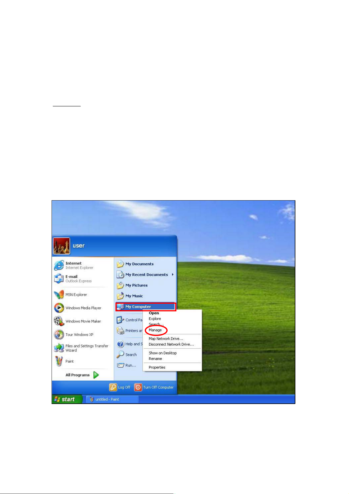
Step 1. Plug the USB cable into the Control Panel’s USB port and connect it to
Step 2. Insert the supplied CD-ROM into your CD-ROM drive and find the
systems.
a PC.
“USB Driver” folder (you may copy and paste the folder to your
desktop for later use). Click the “Start” button at the bottom left-hand
corner of the screen and then click “My Computer” and “Manage.”
9
Page 13
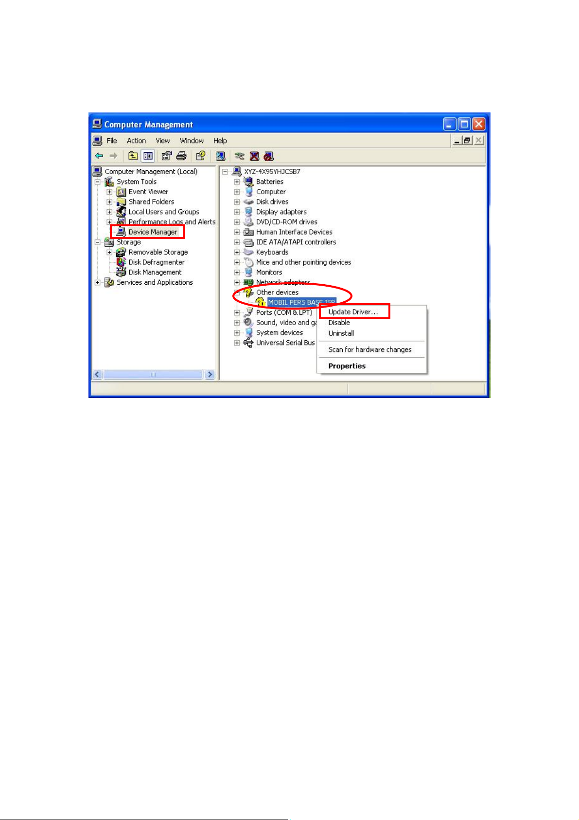
Step 3. Click on the “Device Manager” icon and find “MOBIL PERS BASE ISP”
under “Other devices.” Click “Update Driver.”
10
Page 14
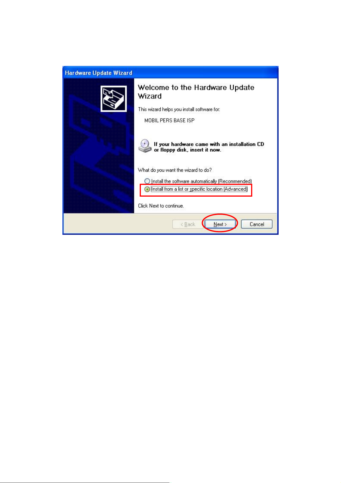
Step 4. When the Hardware Update Wizard window pops up, select “Install
from a list or specific location (Advanced)” and click “Next.”
11
Page 15
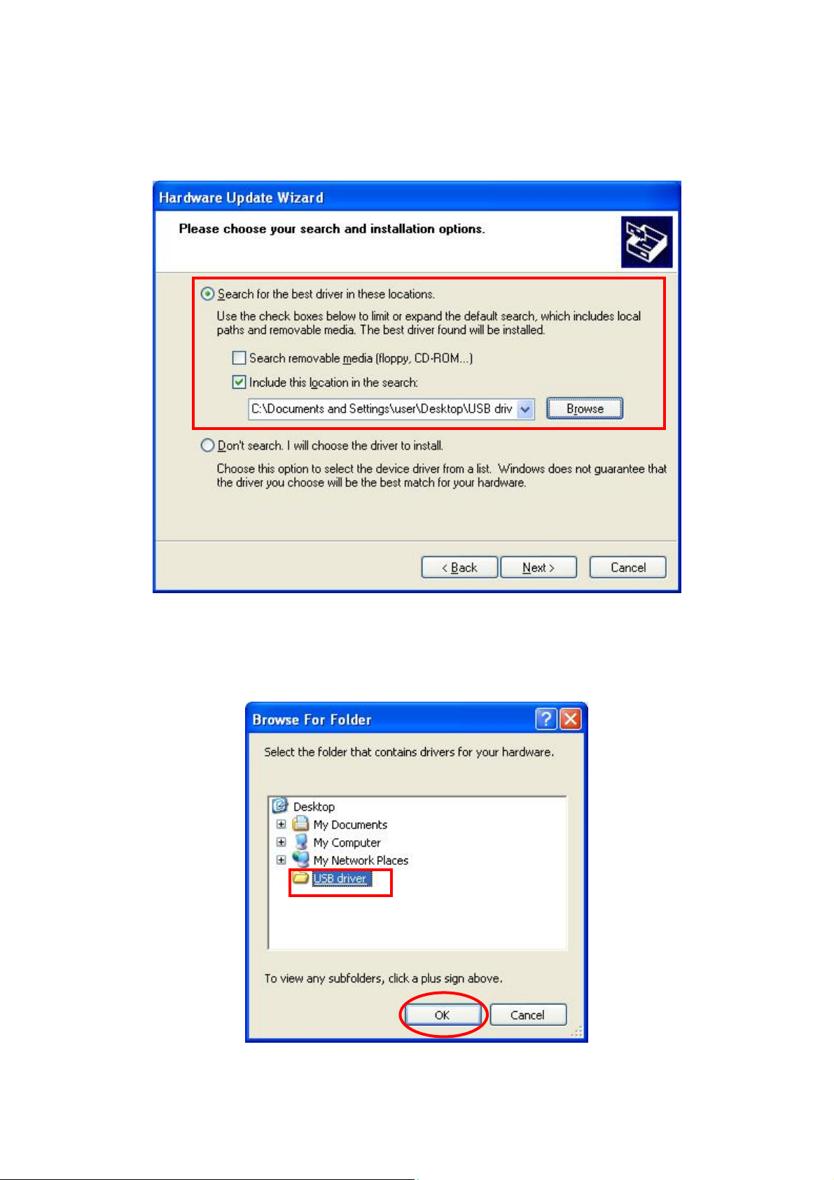
Step 5. Search for the USB Driver folder. If you have copied and pasted the
USB Driver folder to your desktop, tick “Include this location in this
search” and click “Browse.”
Step 6. Select the “USB Driver” and click “OK.”
12
Page 16
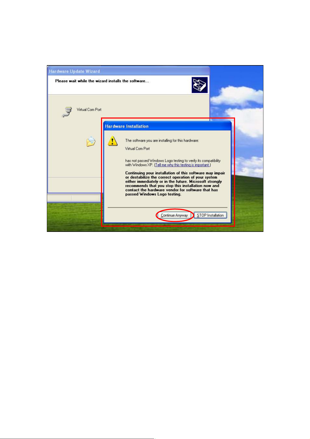
Step 7. It takes a short while for your PC to install the USB Driver. If the
Hardware Installation warning window pops up, please click
“Continue Anyway .”
13
Page 17
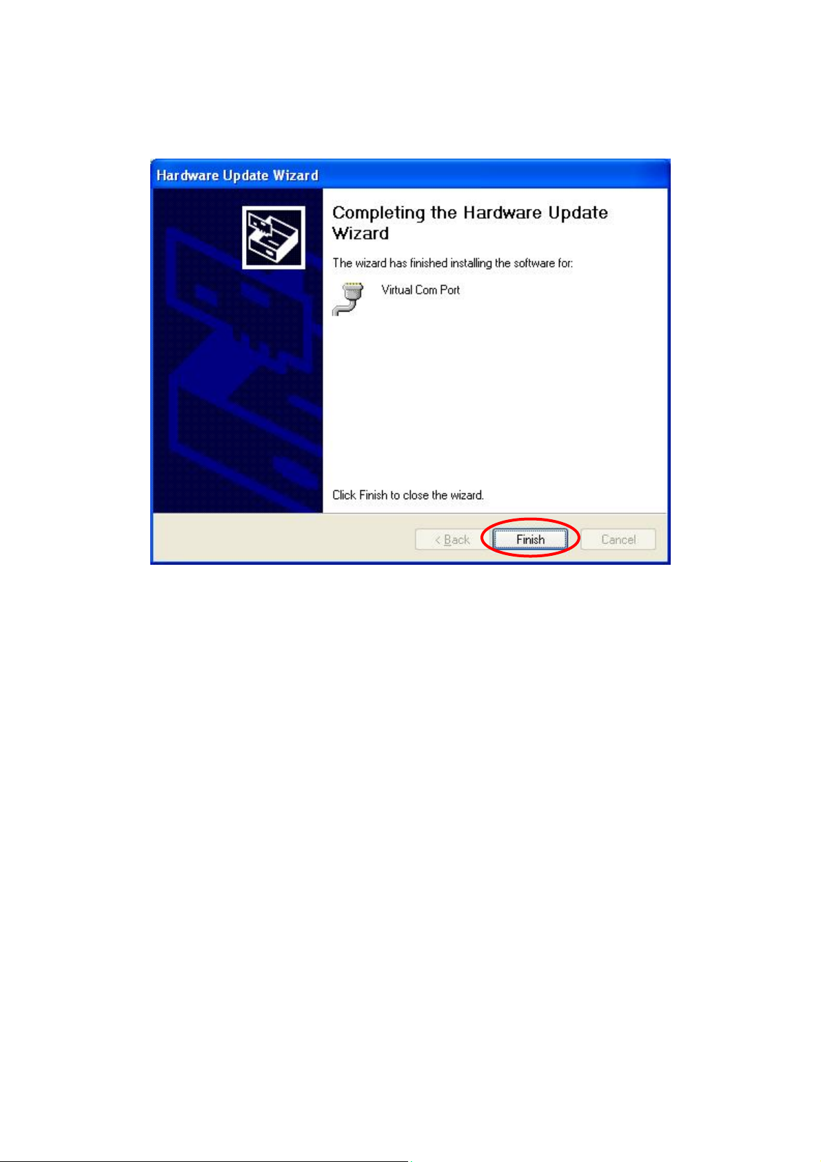
Step 8. When the installation has been completed, click “Finish” on the
Hardware Update Wizard window to close the wizard.
14
Page 18
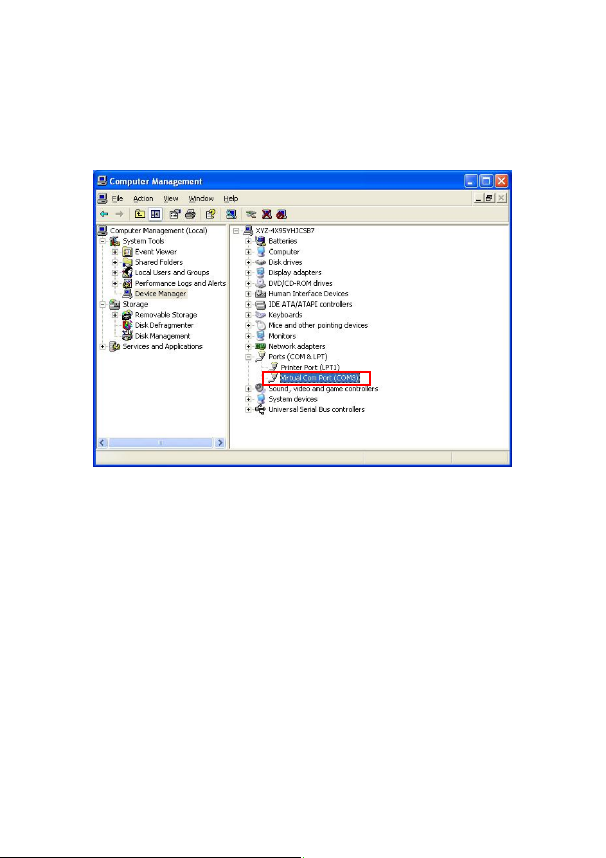
Step 9. Please remember the COM port number of MX as shown in the
“Device Manager” section. You will need the COM port number when
doing PC programming.
Now that the USB Driver has been successfully installed, you can
proceed with PC programming of MX.
15
Page 19
4.1.2. PC Programming Tool
You can easily configure the Control Panel via the PC Programming Tool
provided in the CD-ROM.
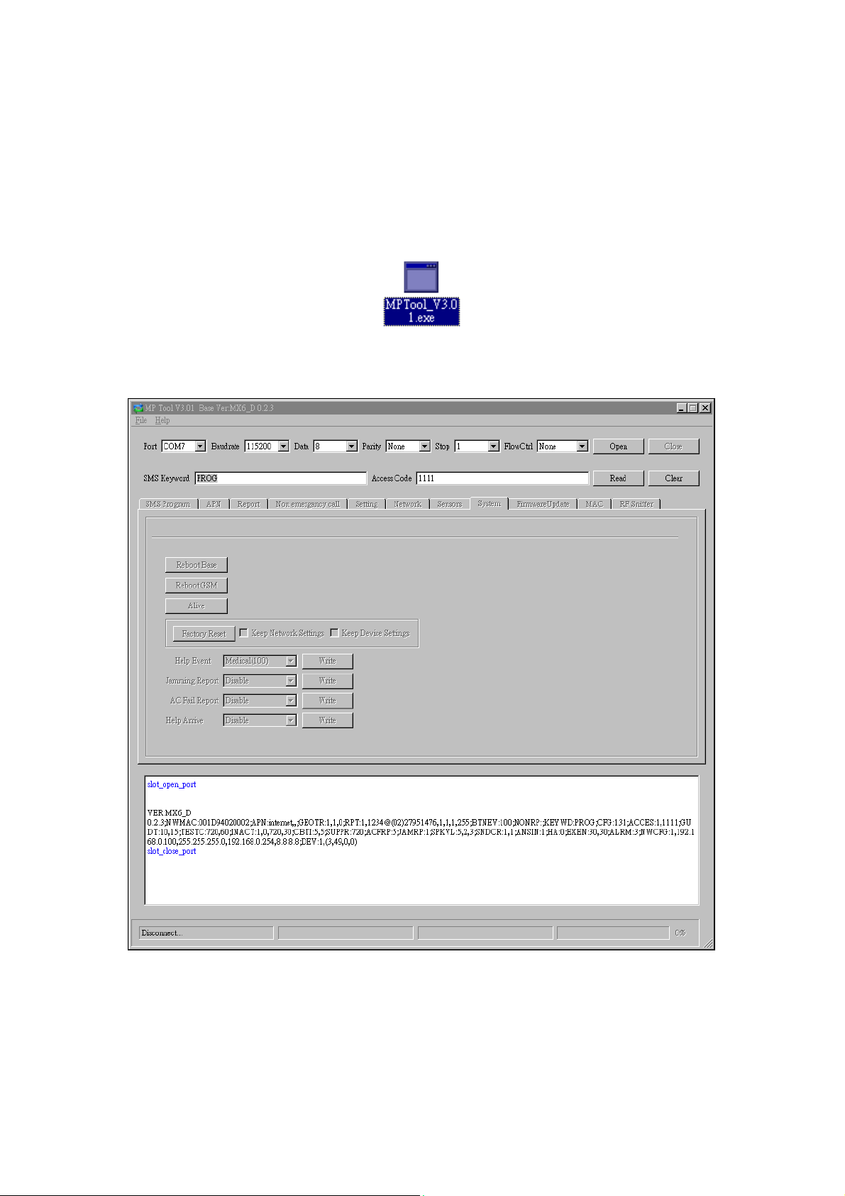
Step 1. Find and open the “PC Programming Tool” folder in the supplied
CD-ROM. Click “MPTool_x.xx.exe” to execute the programming tool.
The following configuration screen will be opened.
16
Page 20
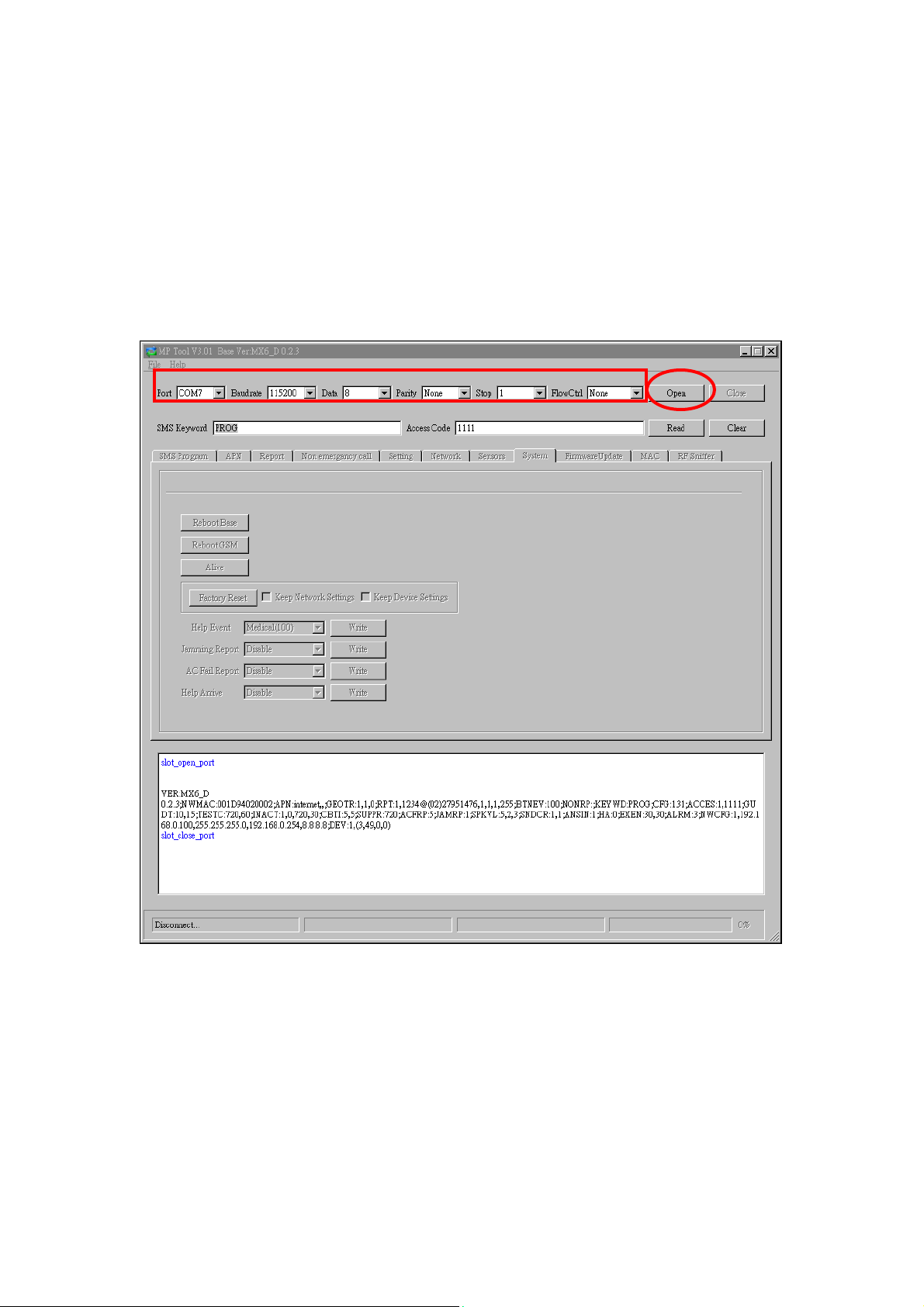
Step 2. Select the following settings in the top section of the configuration
screen and click “Open.”
z Port: Select the COM port generated for MX after installing the
USB Driver (the USB port connected to MX).
z Baud rate: 115200
z Data: 8
z Parity: None
z Stop: 1
z FlowCtrl: None
17
Page 21
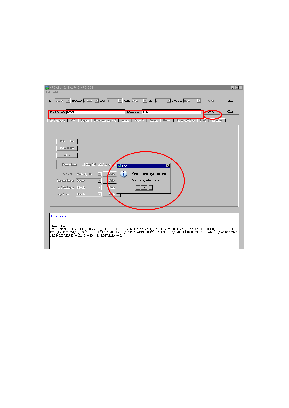
Step 3. Enter SMS Keyword and Access Code and click “Read.” When a
pop-up window shows “Read configuration success,” the
configuration page below will be opened and you can proceed with
the programming of MX.
z SMS Keyword: PROG (default)
z Access Code: 1111 (default)
18
Page 22
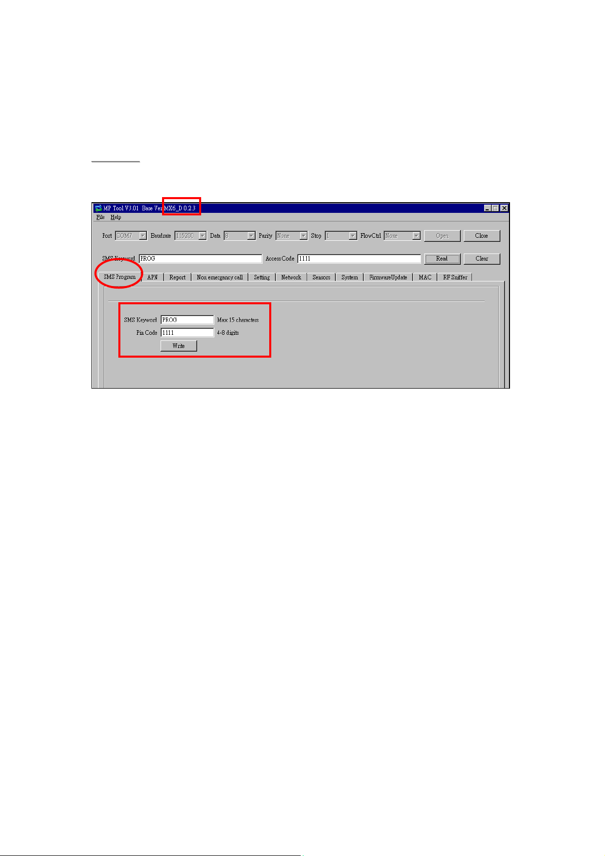
Step 4. SMS Program
Click “SMS Program” to set a SMS Keyword (15 characters max.) and a PIN
Code (4-8 digits) and click “Write.” Please note that the SMS Keyword is
case-sensitive.
<<NNOOTTEE>>
) The version of your MX model will be shown on the top of the screen.
19
Page 23
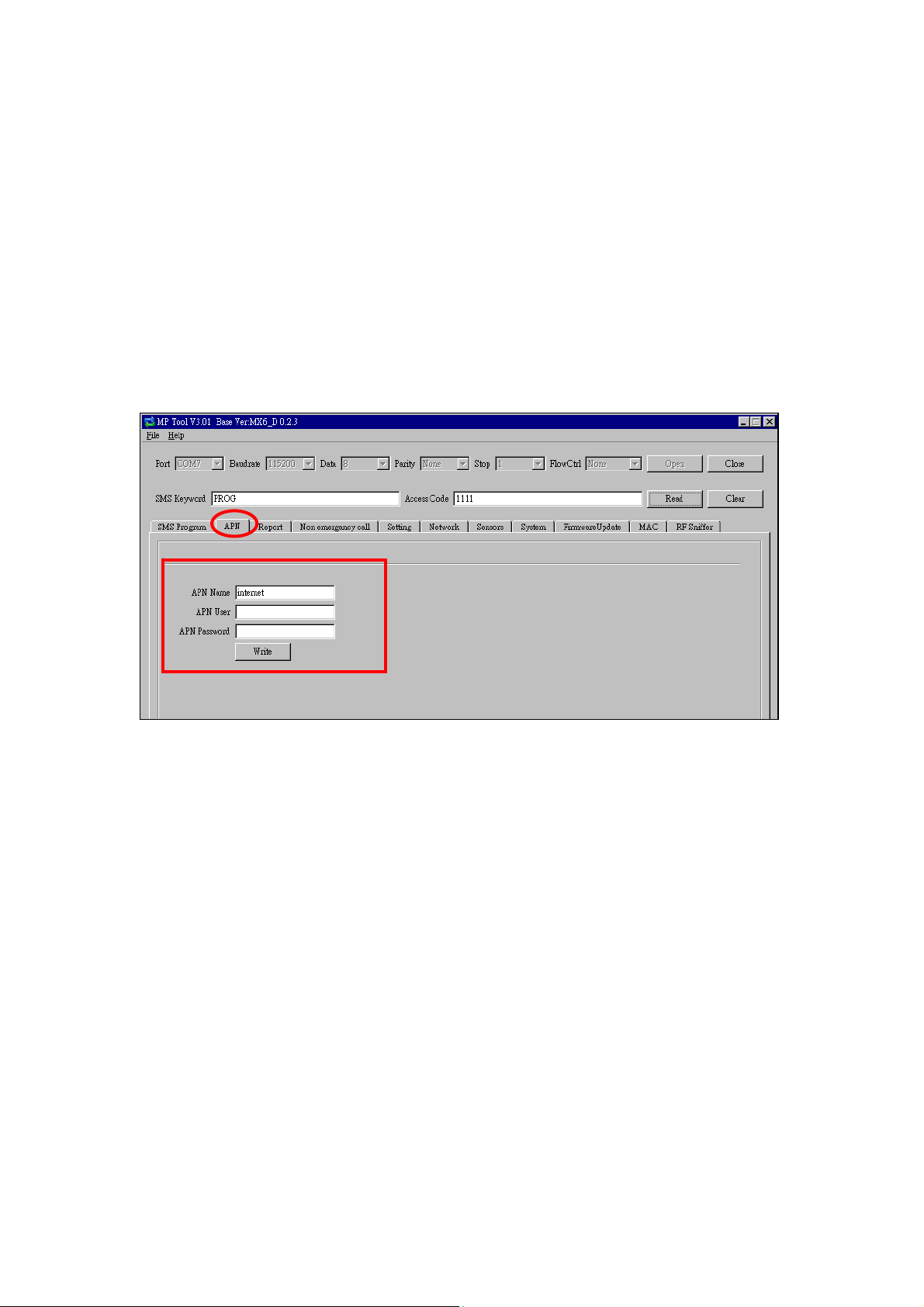
Step 5. APN
Click “APN” to set APN Name, APN User and APN Password and click “Write.”
z Access Point Name (APN): The name of an access point for GPRS.
Please ask your SIM card service provider for your APN.
z Username: Offered by your SIM card service provider. Please ask your
service provider for your GPRS username. If no username is required, you
may skip this step.
z Password: Offered by your SIM card service provider. Please ask your
service provider for your GPRS password. If no password is required, you
may skip this step.
20
Page 24
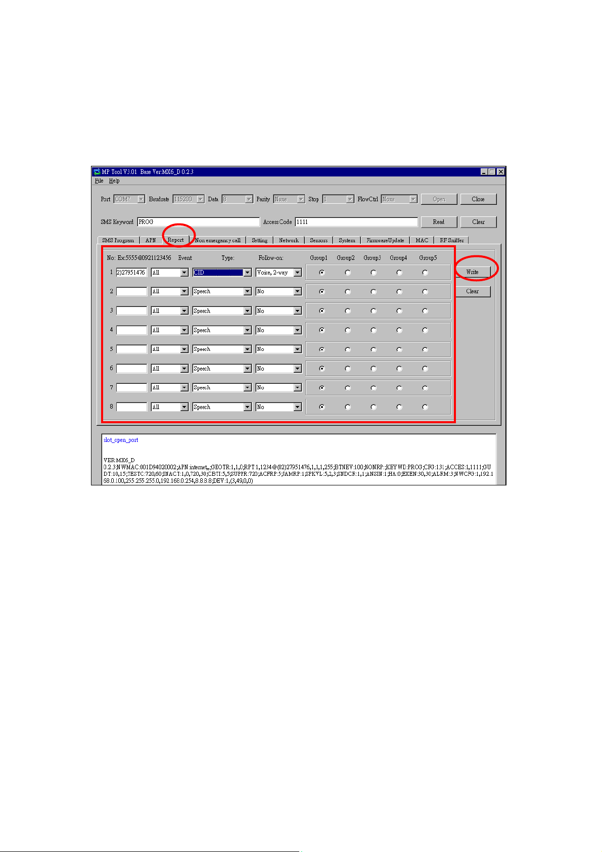
Step 6. Reporting
Click “Report” to program destinations of reporting, event filters (Event),
reporting formats (T ype), fo llow-on options (Follow-on) and reporting sequence
(Group 1~5) for alarm reporting and status reporting. Click “Write” after you
have completed the settings.
z Destinations of reporting 1~8: Program destinations of reporting 1~8 in
the No. 1~No. 8 boxes.
z Event: Event filters have five options, “All,” “Medical,” “Emergency,”
“Status” and “Burglar.” Event filters are used to process events according
to the categories to which they belong. Please refer to “Appendix 7.1.9
Contact ID Event Codes” to check out the categories to which events are
assigned.
z Type: Select a reporting format for each destination of reporting. The
reporting formats include the following: Speech, CID, Scancom, Tunstall,
Franklin, CPC 1, CPC 2, CID_IP, SIA_CID_IP, SIA_IP, SIA_CID_UDP,
SIA_UDP, CSV_IP, SMS_CID, SMS_TEXT, and SMS_SIA.
z Follow-On: Select a follow-on option for each destination of reporting.
The follow-on options include the following: No, 2-way Voice
communication, Talk only, Listen-in only and Wait (for command). The
follow-on options should be in conformity with the settings of their
corresponding destinations of reporting.
21
Page 25

z Group 1~Group 5: Groups 1~5 determine the sequence of reporting. The
reporting sequence goes from Group 1 to Group 5.
The procedure and details of programming are as follows:
1. Programming destinations of reporting: You can set 8 destinations of
reporting. To program destination 1, please first enter its reporting
number/setting in the No. 1 box and select its reporting format under “T ype”
as well as its follow-on option under “Follow-On.” Configure destinations
2-8 in the same manner.
The setting of each destination of reporting shall be in conformity with the
destination’s reporting format under “Type.” Examples of reporting formats
are as follows:
- Reporting over IP (Ethernet or GPRS) in CID_IP/SIA_IP/SIA_CID_IP/
SIA_UDP/SIA_CID_UDP/CSV_IP formats: Account@server:port
example: 0001@59.124.123.66:50123
- Reporting over the phone in CID/Scancom/Tunstall/Franklin/CPC 1/
CPC 2 formats: Account@phone number
Example: 0001@(02)27940559
- Speech reporting over the phone: phone number
Example: 0912345678
- Reporting over the phone in SMS_CID/SMS_TEXT/SMS_SIA formats:
Account@phone number
Example: 0001@0912345678
<<NNOOTTEE>>
) The account number can contain 4 or 6 digits. The CMS may also
determine according to its capacity how many digits the account number
can contain.
) You can select the options in the “Follow-On” column (No/2-Way
Voice/Talk Only/Listen Only/Wait) for digital reporting formats, including
CID, Tunstall, Scancom, Franklin, CPC 1 and CPC 2 formats. Please note
that the “Follow-On” settings for all the other reporting formats have to be
“No.”
) If a destination of reporting contains digits in parentheses like
(02)27940559, the Control Panel will not dial the digits in the parentheses
when reporting via PSTN (it will only dial 27940559) but will dial the digits
in the parentheses when reporting via GSM (it will dial 0227940559).
) Jamming reports can be reported via all reporting formats under “Type”
except for the Scancom and Tunstall formats.
2. Programming event filters: Event filters have five options: “All,”
“Medical,” “Emergency,” “Status” and “Burglar.” Event filters are used to
22
Page 26

process events according to the categories to which they belong. Please
refer to “Appendix 7.1.9. Contact ID Event Codes” to check out the
categories to which events are assigned.
Events are divided into four categories: medical, emergency, status and
burglary. If the option “all” is selected for a destination, all events will be
reported to this destination.
Examples are as follows:
- A device low on battery is a “status” event. If destinations 3 and 7 are set
as “status” and destination 5 as “all” in event filters, this status event will
be reported to destinations 3, 5 and 7.
- A fall sensor being inactive is a “medical” event. If destinations 1 and 6 are
set as “medical” and destination 5 as “all” in event filters, this medical
event will be reported to destinations 1, 5 and 6.
<<NNOOTTEE>>
) Events categorized as “status” do not have follow-on procedure
(2-way/listen in/talk only/wait). Events categorized as “medical,”
“emergency” or “burglary” will have follow-on procedure if you program
follow-on modes for them. The only exception is the home/away events
(the home event code is 3666 and the away event code 1666). These two
events belong to the “status” category but have follow-on procedure.
3. Assigning destinations 1~8 to Groups 1~5: Reporting sequence goes
from Group 1 Æ Group 2 Æ Group 3 Æ Group 4 Æ Group 5. Destinations of
reporting assigned to Group 1 will be reported to first, those assigned to
Group 2 reported to next, and the like.
If you want to assign destination 1 to Group 3, tick Group 3 for destination 1.
Assign destinations 2-8 to the groups in the same manner.
>
<<NNOOTTEE>
) Each group can have more than one destination of reporting. If one group
has more than one destination of reporting, the reporting sequence will go
through all of this group’s destinations before moving on to the next
group’s destination(s).
) The reporting will go through a group’s destinations according to the
numerical sequence to which the destinations are assigned. For example,
when destinations 4 and 8 are assigned to Group 2, the reporting will go to
destination 4 first and then destination 8.
) One complete round of reporting for the system means reporting from
Group 1 Æ Group 2 Æ Group 3 Æ Group 4 Æ Group 5 and going through
all the groups’ destinations. The system will keep going through the
rounds of destinations until one reporting has been received successfully.
If the system has successfully reported to one destination in a group, the
system will consider that it has successfully reported to this group.
23
Page 27

Therefore, the system will skip the rest of the destinations in this group
and go on reporting to the next group. For example, if destinations 2, 4
and 7 are assigned to Group 3 and the system has successfully reported
to destination 2, the system will skip destinations 4 and 7 and go on
reporting to Group 4.
After the system has completed one round of reporting (going from Group
1 Æ Group 2 Æ Group 3 Æ Group 4 Æ Group 5) and has successfully
reported to one group, it will consider that the event has been successfully
reported and will stop reporting. If the successful reporting takes place in
the midst of a round, the system will still report to the rest of the groups in
the round before stopping reporting. For example, if the successful
reporting takes place in Group 2, the system will no longer report to other
destinations in Group 2 but will still go on reporting to destinations in
Group 3, Group 4 and Group 5 before stopping reporting.
If the system has not successfully reported to any group, it will enter the
retry cycle to repeat another round of reporting.
) If no reporting is successfully received after the system has gone through
the first complete round, the system will take a 5-minute break before
starting the second round of reporting. If there is still no reporting
successfully received after the system has gone through the second
round, the system will again take a 5-minute break before starting the third
round of reporting. The system will never stop the reporting cycles unless
one reporting has been received successfully.
24
Page 28
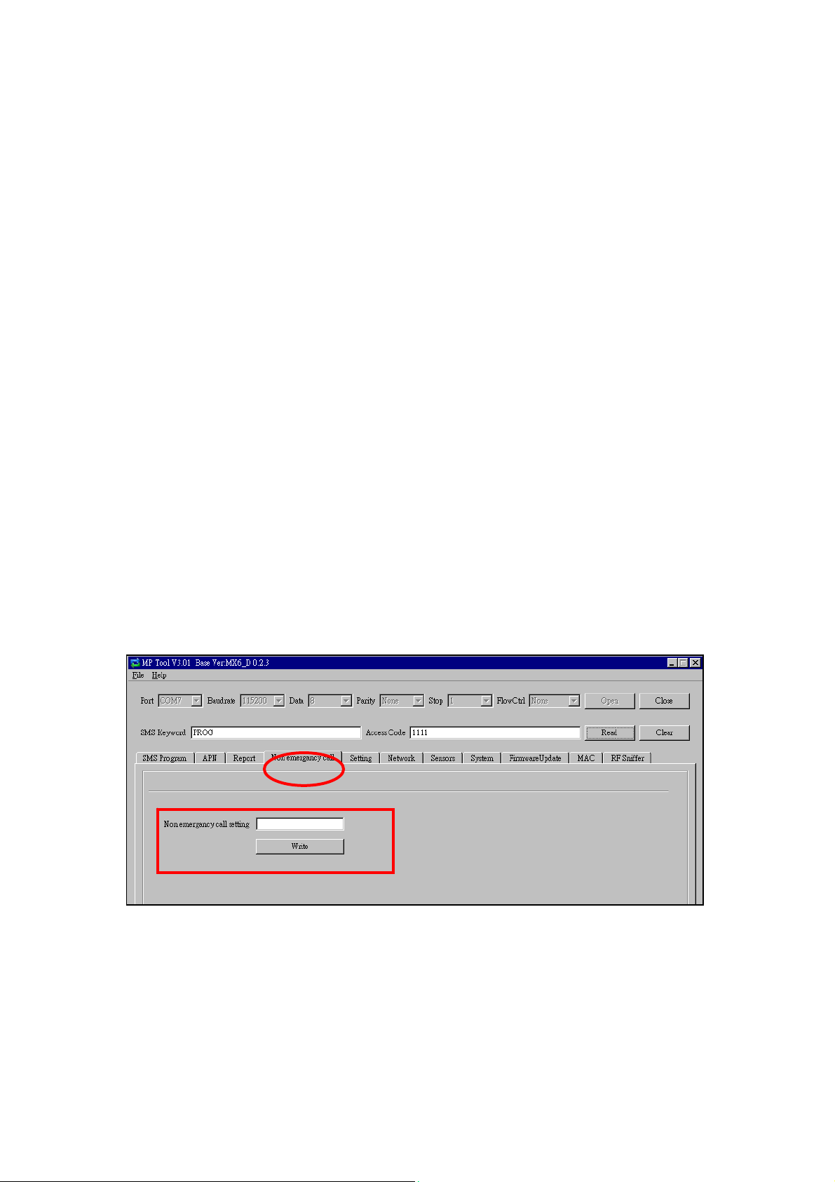
Step 7. Non-Emergency Call
z Click “Non-Emergency Call” to program the non-emergency call number
and click “Write.”
z When the Control Panel is in normal mode, you can make a
non-emergency call by pressing the green reset button for 3 seconds or
press the yellow button once (if the yellow button has been programmed
as a non-emergency call button). The Control Panel will emit 2 beeps and
automatically dial the programmed non-emergency call number for
two-way communication.
z During the conversation of a non-emergency call, you can enter the
following DTMF commands:
- Enter (1) to talk only.
- Enter (2) to open two-way voice communication.
- Enter (3) to listen in only.
- Enter (9) to hang up. You can also put the handset back to the base
cradle to end the call.
z During the conversation of a non-emergency call, you can extend the
communication by entering DTMF command (1), (2) or (3).
z At 20 and 10 seconds before the communication time expires, 1 beep will
be emitted via the telephone handset to alert the user. When the
communication time is up, the call will be automatically terminated.
z The communication time of non-emergency calls is conditioned by the
two-way timer function.
Step 8. Setting
25
Page 29
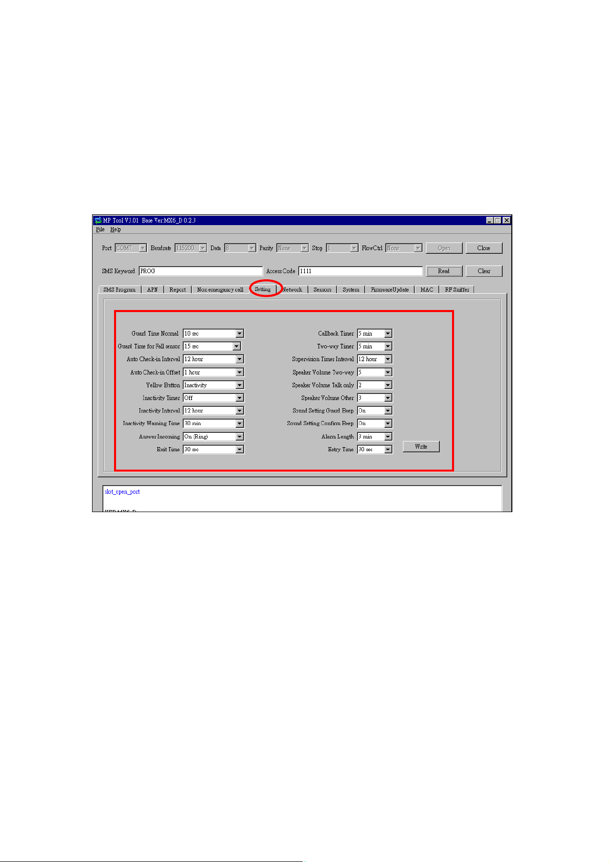
Click “Setting” to program “Guard Time Normal,” “Guard Time for Fall Sensor,”
“Auto Check-In Interval,” “Auto Check-in Offset,” “Yellow Away/Home Button,”
“Inactivity Timer,” “Inactivity Interval,” “Inactivity Warning Time,” “Callback
Timer,” “Two-Way Timer,” “Supervision Timer Interval” and “Speaker Volume
Two-Way,” “Speaker Volume Talk Only,” “Speaker Volume Other,” Sound
Setting Guard Beep,” “Sound Setting Confirm Beep,” “Answer Incoming,”
“Alarm Length,” “Exit Time” and “Entry Time.”
Click “Write” when you have completed these settings.
Details regarding the settings are as follows:
1. Guard Time Normal:
z Guard time normal is designed for any compatible sensor except for Fall
Sensor (fall detection).
z A voice prompt announcing “help call in progress” will be played every 2-3
seconds during guard time to alert the user.
z If a false alarm is triggered, it can be canceled during guard time.
z An emergency alarm cannot be cancelled after guard time has expired.
z If an emergency alarm is triggered by Fall Sensor, guard time will be
determined by the setting of Fall Sensor instead of the setting of guard
time.
2. Guard Timer for Fall Sensor:
26
Page 30

zYou can set a guard time period for Fall Sensor. A voice prompt
announcing “a fall has been detected” will be played every 2-3
seconds during Fall Sensor’s guard time.
zIf a false alarm is triggered by Fall Sensor, it can be canceled within the
guard time period.
zThis function is used when a fall is detected.
3. Auto Check-In Interval:
z You can select the length of the interval between auto check-in reports.
z There will be no auto check-in report if you select “Disable.”
z Whenever programming mode is accessed, the Control Panel will reset
the auto check-in timer.
4. Auto Check-In Offset:
z After power is supplied to the
Control Panel, the system will start counting the time for a check-in
report.
z The Control Panel will send a
check-in report once according to the setting of offset time. Afterwards
it will send reports according to the setting of auto check-in reports
unless the Control Panel restarts or the offset time is reset.
z When offset time is reset in
programming mode, the system will recalculate the time for a check-in
report.
z Whenever programming mode is
accessed, the Control Panel will reset the offset timer.
5. Yellow Button:
zYou can set the yellow button on the Control Panel as an inactivity button,
a check in/out button, an away/home button, a non-emergency call
button or a security button.
zAs an inactivity button: The user can use the inactivity button to toggle
on/off the inactivity timer. When the user presses the inactivity button
to toggle on/off the inactivity timer, the Control Panel does not report
event codes to the CMS.
zAs a check-in/out button: The user can use the check-in/out button to
toggle on/off the inactivity timer. When the user presses the
check-in/out button to check out and toggle off the inactivity timer, the
CID event code 665 with the prefix “1” will be sent to the CMS. When
the user presses the check-in/out button to check in and toggle on the
inactivity timer, the CID event code 665 with the prefix “3” will be sent
to the CMS.
27
Page 31

zAs an away/home button: The user can use the away/home button to
toggle on/off the inactivity timer. When the user presses the
away/home button to toggle off the inactivity timer before leaving home,
the CID event code 666 with the prefix “1” will be reported to the CMS
and two-way communication will be opened after the reporting. When
the user presses the away/home button to toggle on the inactivity timer
upon returning home, the CID event code 666 with the prefix “3” will be
reported to the CMS and two-way communication will be opened after
the reporting.
zAs a non-emergency call button: The user can press this non-emergency
call button to dial a preset phone number.
zAs a security button: The user can press the security button to arm his
house and stop the inactivity timer (when the inactivity timer is set as
“on”). The user can select either of the following two methods to
disarm his house and restart the inactivity timer:
1. Press the security button once and press Wrist Pendant (WTR-)
once within three seconds after the security button is pressed.
2. Use Remote Control (RC) or Remote Keypad (KP) to disarm the
house and the inactivity timer will automatically restart.
<<NNOOTTEE>>
) If the inactivity timer is set as “on,” the timer will stop counting when the
user arms his house and goes out. The timer will start counting all over
again when the user returns home and disarms the house. The orange
backlight of the yellow button will be steady on no matter whether the
timer is stopped or continues running.
) If the inactivity timer is set as “off,” it will remain disabled no matter
whether the user arms or disarms his house. The orange backlight of the
yellow button will be turned off.
6. Inactivity Timer:
z If you set the inactivity timer as “on,” the orange backlight of the
yellow away/home button on the Control Panel will be steady on to
indicate that the inactivity timer is on. If you set the inactivity timer as
“off,” the orange backlight will be off.
z If the setting is “off,” no code will be sent to the CMS.
z When the Control Panel is in idle mode, you can toggle on/off the
inactivity timer by pressing the yellow button once (if the yellow button
has been programmed as an away/home button).
z If the yellow button has been programmed as a non-emergency call
button or a security button, you can only enable or disable the
inactivity timer via programming. However, when the yellow button is
programmed as a security button and the inactivity timer has been
28
Page 32

enabled, the user can stop the inactivity timer when arming his house
and restart the inactivity timer when disarming his house.
<<NNOOTTEE>>
) Please set the inactivity timer as “off” if you program the yellow button as a
non-emergency call button or a security button.
7. Inactivity Interval:
zThis function monitors user movements and sends an inactivity report to
the CMS if the user fails to reset the inactivity timer before the interval
expires. This setting is for you to select the countdown period for the
inactivity timer.
zThe inactivity timer can be reset by pressing the reset button once on the
Control Panel or by an action from any device with a button.
zWhen the inactivity timer expires and no reset signal is received, the
Control Panel will start to play a voice prompt every five minutes to
alert the user during warning time. If a reset signal is still not received
after warning time expires, an inactivity alarm report will be made.
zThe reporting method for an inactivity alarm is the same as that for an
emergency alarm. The report will be sent based on your reporting
methods after the warning time expires.
8. Inactivity Warning Time:
z Inactivity warning time is the interval between the expiry of the
inactivity timer and the Control Panel’s sending an inactivity alarm
report to the CMS.
z The Control Panel will play a voice prompt upon the expiry of the
inactivity timer. Afterwards the voice prompt will be played every 5
minutes during warning time as a reminder to the user until the expiry
of warning time.
z If warning time is disabled, an inactivity alarm report will be
immediately sent to the CMS upon the expiry of the inactivity timer.
9. Callback Time:
z This setting is for digital reporting methods. After reporting
successfully to the CMS, the system will automatically hang up the
line and start a waiting period (=callback time) to auto answer any
incoming calls from the CMS.
z When the CMS calls back within callback time, the system will aut o
answer the call after the first ring and wait for the entry of the proper
Access Code followed by the (#) key within 15 seconds.
z When the correct Access Code is received, the system will open
full-duplex communication to allow the call recipient to speak to the
29
Page 33

CMS directly. You can use DTMF commands to switch
communication methods.
z The Access Code must be entered within 15 seconds, otherwise the
system will disconnect the call automatically.
z Press DTMF (9) or the reset button on the Control Panel to terminate
the call.
z When callback time is up, the system will automatically exit the
waiting mode and return to idle mode.
z The callback function is automatically disabled during an AC power
failure period.
10. Two-Way Timer:
z After the system makes a report to the CMS, it will immediately enter
a two-way communication period as programmed by this setting.
This will enable the user to speak directly with the CMS personnel.
z Pressing an assigned DTMF key can extend the two-way
communication by another two-way period.
11. Supervision Timer Interval:
z This function is not available for Scancom and speech reporting.
z When this supervisory function is enabled, the Control Panel will be
able to receive check-in signals from Wrist Pendants (WTR-),
Smoke Detector, Fall Sensor and Passive Infrared Motion Detector
that indicate the proper operation of the devices.
z When the supervision timer expires and no supervision signal is
received from WTR-, Smoke Detector, Fall Sensor or Passive
Infrared Motion Detector, a supervisory report will be made.
z The reporting method for a supervisory report is the same as that for
an emergency alarm. The report will be sent based on your reporting
method without guard time waiting.
12. Speaker Volume Two-Way:
z Select a preferred speaker volume level for two-way mode.
13. Speaker Volume Talk Only:
z Select a preferred speaker volume level for talk-only mode.
14. Speaker Volume Other:
z Select a preferred speaker volume level for other operations.
15. Sound Setting Guard Beep:
z Select “on” to enable beeps during guard time or “off” to disable the
30
Page 34

beeping sound during guard time.
16. Sound Setting Confirm Beep:
z Select “on” to enable confirmation beeps during reporting or “off” to
disable confirmation beeps during reporting.
17. Answering Incoming [Calls]:
z When this function is set as “on,” the Control Panel rings for incoming
calls. You can answer an incoming call by pressing the red help
button on the Control Panel.
z When this function is set as “off,” the Control Panel remains silent
during incoming calls. Incoming calls will be directly hung up.
18. Alarm Length:
z Select the built-in siren duration when an alarm is activated.
19. Exit Time:
z Select the length of the exit time before your system enters armed
mode upon your departure from home.
20. Entry Time:
z Select the length of the entry time before the system changes from
armed mode to disarmed mode upon your arrival at home.
<<NNOOTTEE>>
) The settings of “Alarm Length,” “Exit Time” and “Entry Time” are functional
only when the yellow button on the Control Panel is programmed as a
security button.
31
Page 35

Step 9.
z Click “Network” to configure networking settings.
z Select “Enable” or “Disable” for the DHCP setting:
Enable: Select “Enable” if a DHCP server is present to enable settings to
be automatically assigned from the server. If you select “Enable,” you can
skip the “IP Address,” “Subnet Mask,” “Default Gateway” and “Default
DNS” settings. These settings will be automatically assigned. Click “Write”
directly after you have selected “Enable” for the DHCP setting.
Disable: Select “Disable” if a DHCP server is not available. If you select
“Disable,” you will have to configure the following “IP Address,” “Subnet
Mask,” “Default Gateway” and “Default DNS” settings. Click “Write” after
you have configured these settings.
32
Page 36

Step 10. Sensors
1. Viewing the data of sensors:
When you have learned sensors into the Control Panel via the local
learning method (see 5.1. Learning in Pendant #1, Pendant #2 and
Other Devices), you can click “Sensors” and “Read” to view the zone
numbers, types, battery status, tamper conditions, operating status and
sound attributes of all of the sensors that have been learned in.
33
Page 37

2. Adding sensors:
zIn addition to the local learning method, you can also use the “Add
Sensor” section on the “Sensors” page to learn sensors into the
Control Panel.
zEnter the zone number (Zone 1~Zone 100) to which you wish to assign a
sensor and the Sensor ID, which is the barcode on the back of the
sensor, and click “Add Sensor.” You can enter 1~100 in the zone
number box. A sensor ID is a combination of digits 1-9 and characters
A-F and can contain 10 or 14 characters (can be uppercase or
lowercase characters).
zIf the sensor is successfully added, this sign will pop up on
the screen. An “OK” will be shown at the bottom left-hand corner of the
screen and the newly added sensor will appear on the sensor list.
zIf you click “Add Sensor” and the word “Error” is shown at the bottom
left-hand corner of the screen, you may check whether the Sensor ID
is correct and whether the zone to which you assigned the sensor has
been occupied.
34
Page 38

3. Editing and removing sensors:
z Editing the sound attribute of a sensor: Clic k any box in the section of the
sensor that you wish to configure. For example, if you wish to edit the
sound attribute of the sensor in Zone 3, you can click any box in the Zone
3 section. The “Dialog” pop-up window will be shown.
If you want the sensor in Zone 3 to be silent, tick “Silent” and “Edit.” If you
don’t want the sensor to be silent, leave the box in front of “Silent” blank
and tick “Edit.”
z Removing a sensor: If you want to remove the sensor in Zone 3, click
“Delete” on the popup window and the sensor will be removed. All devices
can be removed via PC programming.
z Click “Cancel” to close the “Dialog” popup window.
35
Page 39

Step 11. System
When you click “System” to enter the “System” screen, you can carry out the
following operations:
1. Rebooting the Control Panel:
zYou can click “Reboot Base” to reboot the Control Panel. The Control
Panel will emit 2 beeps about 2 seconds after you click the “Reboot
Base” button. The following screen will be automatically closed and
you will need to restart the PC Programming Tool for further operation.
zRebooting the Control Panel will not affect the Control Panel’s
programmed parameters.
36
Page 40

2. Rebooting GSM:
zIf this command is successful, the message “<OK> RSTG” will be shown
at the bottom left-hand corner of the screen.
37
Page 41

3. Checking the condition of the Control Panel:
zYou can click “Alive” to check if the Control Panel can respond to your
commands properly.
zIf the Control Panel responds properly , the message “<OK> ECHO” will be
shown at the bottom left-hand corner of the screen.
38
Page 42

4. Restoring the system to factory settings:
zYou can click “Factory Reset” to restore the system to factory settings.
The system will immediately restore all programmed parameters to
factory settings and the Control Panel will emit 2 beeps after you click
the “Factory Reset” button.
zIf you want to keep your network settings and/or device settings, please
click the box(s) before these specifications before clicking “Factory
Reset.” Your network settings and/or device settings will then be
preserved while other programmed parameters are restored to factory
defaults.
zPlease do not close the configuration screen while the system is being
restored to factory defaults. It will take at least 3 minutes for the system
to complete this step.
zAfter the system has been restored to factory settings, you have two
options to proceed with further operation:
- You can close the PC Programming Tool and restart it, or
- You can click “Clear” and then “Read” to view the renewed settings.
39
Page 43

5. Selecting an event code:
zYou can select the event code to be sent to the CMS when the red button
of the Control Panel is pressed. Choose your preferred event code in
the box after “Help Event” and click “Write.”
zThere are four options for the event code:
- 100: Medical
- 101: Emergency
- 130: Burglary
- 120: Panic
40
Page 44

6. Jamming reports:
z You can select to enable or disable jamming reports. Select your
setting in the box after “Jamming Report” and click “Write.”
z Jamming reports can only be sent in the CID format and not in the
Scancom or Tunstall format.
41
Page 45

7. AC power failure reports:
z You can disable AC power failure reports or set the interval between
an AC power failure and the reporting of the power failure. Select your
setting in the box after “AC Fail Report” and click “Write.”
42
Page 46

8. The help arrival function:
z You can select to enable or disable the help/nurse arrival function .
43
Page 47

Step 12. Firmware Update
z You can update the firmware of MX by clicking on the “Firmware
Update” and the “Open File” buttons. Select the provided firmware
and a “Firmware Updating! Do not close program!” pop-up window
will appear. Click “OK” on the pop-up window for the updating process
to begin.
z The firmware update will take about 5 minutes to complete. Do not
close the PC programming tool while the updating process continues.
44
Page 48

z When the firmware update is complete, a pop-up window will show
“Please wait for Panel restart.” Click “OK” on the pop-up window. The
countdown to the restart of the Control Panel will appear in the white
space at the bottom of the page. After the countdown, the Control
Panel will restart and emit 2 beeps. Do not close the PC programming
tool.
z After the restart of the Control Panel, click on the “Open” and the
“Read” buttons on the PC programming tool. The new firmware
version will be shown on the upper left-hand corner of the page.
45
Page 49

Step 13. RF Sniffer
z “RF Sniffer” is designed for the Control Panel to report to the monitoring
center when it receives a signal from a RF device that it has not learned. If
you select “Disable,” the Control Panel will not report to the monitoring
center when receiving such a signal. If you select “Enable,” the Control
Panel will report to the monitoring center when receiving such a signal.
z If you select “Enable,” please enter the “RF Sniffer URL” for the Control
Panel to report the signal and the ID of the RF device. Please program the
URL in the UDP format: Account@server:port (example:
0001@59.124.123.66:50123) Click “Write” after you complete the
settings.
46
Page 50

4.2. Web Programming
4.2.1. Installing the Finder Software
<<NNOOTTEE>>
) This installation is required only of the first-time user.
) Web programming is applicable to MX-6 and MX-8 only.
) Before you begin web programming, please make sure that you have
plugged an IP cable into the Control Panel’s Ethernet port and connected
the cable to an Ethernet network for MX to operate via Ethernet.
Step 1. Insert the supplied CD-ROM into your CD-ROM drive.
Step 2. Find the “Finder” software in the CD-ROM.
Step 3. Click on “Finder” to initiate the installation.
Step 4. Click on “Next” to rename the shortcut folder. If no renaming is
required, please click “Next” again to get ready for the installation.
Step 5. Click on “Next” again to begin the installation. Click on “Finish” when
the installation is completed.
Step 6. A new icon will be displayed on your desktop.
47
Page 51

Step 7. Click “Finder.exe” to start the installation. The following screen will be
displayed:
Step 8. Click on “Search” for the software to start searching for a recognized
IP address within the local network service.
Step 9. You will be able to see your MX’s IP address on the list. The pop-up
window will display the product version and the MAC address of
your MX.
Step 10. After MX is identified, click on “Open Web Page” and enter the
username “admin” and password “admin1234” to be connected to the
configuration web page.
Step 11. The installation of the “Finder” software for MX is now completed.
48
Page 52

>
<<NNOOTTEE>
) If you need to enter your internet data manually, click on the “Configure
Setting” button.
Enter your internet data, the MX username (default: admin) and password
(default: admin1234) and click on “OK” to confirm the settings. If the username
and password are correct, a pop-up window will display “Status: Configure
success!!”
49
Page 53

4.2.2. Programming MX
Step 1. Getting Connected to the Welcome Page
The welcome page to which your MX is connected will show the following
information:
z Firmware revision: The firmware version of the Control Panel
z MAC address: The MAC address of your MX
50
Page 54

Step 2. Programming the Control Panel
Click on “Panel” at the top of the page to enter the “Panel Setting” page and to
configure the Control Panel’s settings. Click on “Submit Query” to save your
settings or click on “Reset” to return to default settings.
The details are as follows:
1. IDs: Please leave the boxes blank.
2. Keyword: Set a SMS keyword (15 characters max.). The default is PROG.
3. Non-emergency: Enter a non-emergency call number.
zWhen the Control Panel is in normal mode, you can make a
non-emergency call by pressing the green reset button for 3 seconds
or press the yellow button once (if the yellow button has been
programmed as a non-emergency call button). The Control Panel will
emit 2 beeps and automatically dial the programmed non-emergency
call number for two-way communication.
zDuring the conversation of a non-emergency call, you can enter the
following DTMF commands:
- Enter (1) to talk only.
- Enter (2) to open two-way voice communication.
- Enter (3) to listen in only.
- Enter (9) to hang up. You can also put the handset back to the base cradle
to end the call.
zDuring the conversation of a non-emergency call, you can extend the
communication by entering DTMF command (1), (2) or (3).
51
Page 55

zAt 20 and 10 seconds before the communication time expires, 1 beep will
be emitted via the telephone handset to alert the user. When the
communication time is up, the call will be automatically terminated.
zThe communication time of non-emergency calls is conditioned by the
two-way timer function.
4. Speaker Volume:
z Two-way: Select a preferred speaker volume level for two-way mode.
z Talk only: Select a preferred speaker volume level for talk-only mode.
z Others: Select a preferred speaker volume level for other operations.
5. AC Fail Report: You can disable AC power failure reports or set the interval
between an AC power failure and the reporting of the power failure.
6. Jamming Report: You can select to enable (“On”) or disable (“Of f”) jamming
reports. Jamming reports can be sent in the CID format but not in the
Scancom or Tunstall format.
7. Supervision Timer:
zThis function is not available for Scancom and speech reporting.
zWhen this supervisory function is enabled, the Control Panel will be able
to receive check-in signals from Wrist Pendants (WTR-), Smoke
Detector, Fall Sensor and Passive Infrared Motion Detector that
indicate the proper operation of the devices.
zWhen the supervision timer expires and no supervision signal is received
from WTR-, Smoke Detector, Fall Sensor or Passive Infrared Motion
Detector, a supervisory report will be made.
zThe reporting method for a supervisory report is the same as that for an
emergency alarm. The report will be sent based on your reporting
method without guard time waiting.
8. Auto Check-in:
zInterval:
- You can select the length of the interval between auto check-in
reports.
- There will be no auto check-in report if you select “Disable.”
- Whenever programming mode is accessed, the Control Panel will
reset the auto check-in timer.
zOffset Period:
- After power is supplied to the
Control Panel, the system will start counting the time for a check-in
report.
- The Control Panel will send a
52
Page 56

check-in report once according to the setting of the offset period.
Afterwards it will send reports according to the setting of auto
check-in reports unless the Control Panel restarts or the offset
period is reset.
- When the offset period is reset in
programming mode, the system will recalculate the time for a
check-in report.
- Whenever programming mode is
accessed, the Control Panel will reset the offset timer.
9. Sound Setting:
z Guard Beep: Select “on” to enable beeps during guard time or “off” to
disable the beeping sound during guard time.
z Confirm Beep: Select “on” to enable confirmation beeps during
reporting or “off” to disable confirmation beeps during reporting.
10. Guard Time:
z Normal:
- Guard time normal is designed for any compatible sensor except
for Fall Sensor (fall detection).
- A voice prompt announcing “help call in progress” will be played
every 2-3 seconds during guard time to alert the user.
- If a false alarm is triggered, it can be canceled during guard time.
- An emergency alarm cannot be cancelled after guard time has
expired.
- If an emergency alarm is triggered by Fall Sensor, guard time will
be determined by the setting of Fall Sensor instead of the setting
of guard time.
z For Fall Sensor:
- You can set a guard time period for Fall Sensor. A voice prompt
announcing “a fall has been detected” will be played every 2-3
seconds during Fall Sensor’s guard time.
- If a false alarm is triggered by Fall Sensor, it can be canceled
within the guard time period.
- This function is used when a fall is detected.
11. Exit Time: Select the length of the exit time before your system enters
armed mode upon your departure from home.
12. Entry Time: Select the length of the entry time before the system changes
from armed mode to disarmed mode upon your arrival at home.
13. Alarm Length: Select the built-in siren duration when an alarm is activated.
<<NNOOTTEE>>
) The settings of “Exit Time,” “Entry Time” and “Alarm Length” are functional
only when the yellow button on the Control Panel is programmed as a
53
Page 57

security button.
14. Yellow Button:
z You can set the yellow button on the Control Panel as an inactivity
button, a check in/out button, an away/home button, a
non-emergency call button or a security button.
z As an inactivity button: The user can use the inactivity button to
toggle on/off the inactivity timer. When the user presses the inactivity
button to toggle on/off the inactivity timer , the Control Panel does not
report event codes to the CMS.
z As a check-in/out button: The user can use the check-in/out button to
toggle on/off the inactivity timer. When the user presses the
check-in/out button to check out and toggle off the inactivity timer,
the CID event code 665 with the prefix “1” will be sent to the CMS.
When the user presses the check-in/out button to check in and
toggle on the inactivity timer, the CID event code 665 with the prefix
“3” will be sent to the CMS.
z As an away/home button: The user can use the away/home button to
toggle on/off the inactivity timer. When the user presses the
away/home button to toggle off the inactivity timer before leaving
home, the CID event code 666 with the prefix “1” will be reported to
the CMS and two-way communication will be opened after the
reporting. When the user presses the away/home button to toggle on
the inactivity timer upon returning home, the CID event code 666
with the prefix “3” will be reported to the CMS and two-way
communication will be opened after the reporting.
z As a non-emergency call button: The user can press this
non-emergency call button to dial a preset phone number.
z As a security button: The user can press the security button to arm
his house and stop the inactivity timer (when the inactivity timer is set
as “on”). The user can select either of the following two methods to
disarm his house and restart the inactivity timer:
1. Press the security button once and press Wrist Pendant (WTR-)
once within three seconds after the security button is pressed.
2. Use Remote Control (RC) or Remote Keypad (KP) to disarm the
house and the inactivity timer will automatically restart.
<<NNOOTTEE>>
) If the inactivity timer is set as “on,” the timer will stop counting when the
user arms his house and goes out. The timer will start counting all over
again when the user returns home and disarms the house. The orange
backlight of the yellow button will be steady on no matter whether the
timer is stopped or continues running.
54
Page 58

) If the inactivity timer is set as “off,” it will remain disabled no matter
whether the user arms or disarms his house. The orange backlight of the
yellow button will be turned off.
15. Inactivity Timer:
z Inactivity T imer:
- If you set the inactivity timer as “On,” the orange backlight of the
yellow button on the Control Panel will be steady on to indicate
that the inactivity timer is on. If you set the inactivity timer as
“Off,” the orange backlight will be off.
- If the setting is “Off,” no code will be sent to the CMS.
- When the Control Panel is in idle mode, you can toggle on/off the
inactivity timer by pressing the yellow button once if the yellow
button has been programmed as an inactivity button, a
check-in/out button or an away/home button.
- If the yellow button has been programmed as a non-emergency
call button or a security button, you can only enable or disable
the inactivity timer via programming. However, when the yellow
button is programmed as a security button and the inactivity
timer has been enabled, the user can stop the inactivity timer
when arming his house and restart the inactivity timer when
disarming his house.
<<NNOOTTEE>>
) Please set the inactivity timer as “off” if you program the yellow button as a
non-emergency call button or a security button.
z Interval:
- This function monitors user movements and sends an inactivity
report to the CMS if the user fails to reset the inactivity timer
before the interval expires. This setting is for you to select the
countdown period for the inactivity timer.
- The inactivity timer can be reset by pressing the reset button
once on the Control Panel or by an action from any device with a
button.
- When the inactivity timer expire s and no reset signal is received,
the Control Panel will start to play a voice prompt every five
minutes to alert the user during warning time. If a reset signal is
still not received after warning time expires, an inactivity alarm
report will be made.
- The reporting method for an inactivity alarm is the same as that
for an emergency alarm. The report will be sent based on your
reporting methods after the warning time expires.
z Warning Interval:
- The warning interval is the interval between the expiry of the
inactivity timer and the Control Panel’s sending an inactivity
alarm report to the CMS.
55
Page 59

- The Control Panel will play a voice prompt upon the expiry of the
inactivity timer. Afterwards the voice prompt will be played every
5 minutes during the warning interval as a reminder to the user
until the expiry of warning time.
- If the warning interval is disabled, an inactivity alarm report will
be immediately sent to the CMS upon the expiry of the inactivity
timer.
16. Help Event Code:
z You can select the event code to be sent to the CMS when the red
button of the Control Panel is pressed.
z There are four options for the event code:
- Medical (100)
- Emergency (101)
- Burglary (130)
- Panic (120)
17. Two-way Timer:
z After the system makes a report to the CMS, it will immediately enter
a two-way communication period as programmed by this setting.
This will enable the user to speak directly with CMS personnel.
z Pressing an assigned DTMF key can extend the two-way
communication by another two-way period.
18. Callback Timer:
z This setting is for digital reporting methods. After reporting
successfully to the CMS, the system will automatically hang up the
line and start a waiting period (=callback time) to auto answer any
incoming calls from the CMS.
z When the CMS calls back within callback time, the system will auto
answer the call after the first ring and wait for the entry of the proper
Access Code followed by the (#) key within 15 seconds.
z When the correct Access Code is received, the system will open
full-duplex communication to allow the call recipient to speak to the
CMS directly. You can use DTMF commands to switch
communication methods.
z The Access Code must be entered within 15 seconds, otherwise the
system will disconnect the call automatically.
z Press DTMF (9) or the reset button on the Control Panel to terminate
the call.
z When callback time is up, the system will automatically exit the
waiting mode and return to idle mode.
z The callback function is automatically disabled during an AC power
56
Page 60

failure period.
19. Answering Incoming [Calls]:
z When this function is set as “On,” the Control Panel rings for incoming
calls. You can answer an incoming call by pressing the red help
button on the Control Panel.
z When this function is set as “Off,” the Control Panel remains silent
during incoming calls. Incoming calls will be directly hung up.
20. Help Arrive: Select “On” to enable the help/nurse arrival function or “Off” to
disable the help/nurse arrival function.
21. Reset:
z You can click on the “Reset” button at the bottom of the page (shown
in the picture below) to reboot the Control Panel. The Control Panel
will emit 2 beeps about 2 seconds after you click the “Reset” button.
z Rebooting the Control Panel will not affect the Control Panel’s
programmed parameters.
<<NNOOTTEE>>
)
PPlleeaassee cclliicckk oonn tthhee ““RReesseett”” bbuuttttoonn aass mmaarrkkeedd bbeellooww ttoo rreebboooott tthhee CCoonnttrrooll
PPaanneell.. TThhee ““RReesseett”” bbuuttttoonn nneexxtt ttoo tthhee ““SSuubbmmiitt QQuueerryy”” bbuuttttoonn iiss uusseedd ttoo
rreessttoorree sseettttiinnggss oonn tthhiiss ppaaggee ttoo ddeeffaauulltt vvaalluueess..
22. Factory Reset:
z You can click on “Factory Reset” to restore the system to factory settings.
The system will immediately restore all programmed parameters to factory
settings and the Control Panel will emit 2 beeps after you click the
“Factory Reset” button.
z If you want to keep your network settings and/or device settings, please
click the box(s) before these specifications before clicking “Factory
Reset.” Your network settings and/or device settings will then be
preserved while other programmed parameters are restored to factory
57
Page 61

defaults.
<<NNOOTTEE>>
) After you click on “Submit Query” to save the settings, these words
“Updated successfully” will be shown at the top the page to confirm that
the Control Panel’s settings have been successfully updated.
58
Page 62

Step 3. APN
Click on “Mobile” at the top of the page. Configure GPRS settings and click on
“Submit Query” to save your settings. Click on “Reset” if you want to restore
the settings to default values.
The details are as follows:
1. GPRS settings:
zAccess Point Name (APN): The name of an access point for GPRS.
Please ask your SIM card service provider for your APN.
zUsername: Offered by your SIM card service provider. Please ask your
service provider for your GPRS username. If no username is required,
you may skip this step.
zPassword: Offered by your SIM card service provider. Please ask your
service provider for your GPRS password. If no password is required,
you may skip this step.
2. GPS Location: Please skip this setting.
3. Cell Locate: Please skip this setting.
4. Tracker Period: Please skip this setting.
59
Page 63

5. Reset GSM: If this command is successful, the words “Updated
successfully” will be shown at the top of the page.
Step 4. Network Settings
z Select “On” or “Off” for the DHCP setting.
z DHCP “On”: Select “On” if a DHCP server is present to enable settings to
be automatically assigned from the server. If you select “On,” you can skip
the “IP Address,” “Subnet Mask,” “Default Gateway” and “Default DNS”
settings. These settings will be automatically assigned. Click “Submit
Query” directly after you have selected “On” for the DHCP setting.
z DHCP “Off”: Select “Off” if a DHCP server is not available. If you select
“Off,” you will have to configure the following “IP Address,” “Subnet Mask,”
“Default Gateway” and “Default DNS” settings. Click “Submit Query” after
you have configured these settings.
z SNTP and Interval: This link will automatically correct and update the
real-time system in your Control Panel and enable the Control Panel to
keep track of the current time. The updates will take place periodically
according to the “Interval” setting. It is recommended that you do not
change the website setting of SNTP unless you know a website that can
enable your Control Panel to keep track of your current local time.
60
Page 64

Step 5. User Code (Access Code)
Program user code(s) on this page and click on “Submit Query” to save your
setting(s). The default is 1111.
61
Page 65

Step 6. Report Settings
Click “Report” to program destinations of reporting, event filters (Event),
reporting formats (Type), follow-on options (Option) and reporting sequence
(Group 1~5) for alarm reporting and status reporting. Click on “Submit Query”
after you have completed the settings.
z Destinations of reporting 1~8: Program destinations of reporting 1~8 in
the No. 1~No. 8 boxes.
z Event: Event filters have five options, “medical,” “emergency,” “status,”
“burglary” and “all.” Event filters are used to process events according to
the categories to which they belong. Please refer to “Appendix 7.1.9
Contact ID Event Codes” to check out the categories to which events are
assigned.
z Type: Select a reporting format for each destination of reporting. The
reporting formats include the following: speech, CID, Scancom, Tunstall,
Franklin, CPC 1, CPC 2, CID_IP, SIA_IP, SIA_CID_IP, SIA_UDP,
SIA_CID_UDP, CSV_IP, SMS_CID, SMS_TEXT, and SMS_SIA.
z Follow-On: Select a follow-on option for each destination of reporting.
62
Page 66

The follow-on options include the following: No, 2-way voice
communication, talk only, listen-in only and wait (for command). The
follow-on options should be in conformity with the settings of their
corresponding destinations of reporting.
z Group 1~Group 5: Groups 1~5 determine the sequence of reporting. The
reporting sequence goes from Group 1 to Group 5.
The procedure and details of programming are as follows:
4. Programming destinations of reporting: You can set 8 destinations of
reporting. To program destination 1, please first enter its reporting
number/setting in the No. 1 box and select its reporting format under “T ype”
as well as its follow-on option under “Follow-On.” Configure destinations
2-8 in the same manner.
The setting of each destination of reporting shall be in conformity with the
destination’s reporting format under “Type.” Examples of reporting formats
are as follows:
- Reporting over IP (Ethernet or GPRS) in CID_IP/SIA_IP/SIA_CID_IP/
SIA_UDP/SIA_CID_UDP/CSV_IP formats: Account@server:port
(example: 0001@59.124.123.66:50123)
- Reporting over the phone in CID/Scancom/Tunstall/Franklin/CPC 1/
CPC 2 formats: Account@phone number (example:
0001@0912345678)
- Speech reporting over the phone or reporting over the phone in
SMS_CID/SMS_TEXT/SMS_SIA formats: phone number (example:
0912345678)
>
<<NNOOTTEE>
) The account number can contain 4 or 6 digits. The CMS may also
determine according to its capacity how many digits the account number
can contain.
) You can select the options in the “Follow-On” column (No/2-Way
Voice/Talk Only/Listen Only/Wait) for digital reporting formats, including
CID, Tunstall, Scancom, Franklin, CPC 1 and CPC 2 formats. Please note
that the “Follow-On” settings for all the other reporting formats have to be
“No.”
) If a destination of reporting contains digits in parentheses like
(02)27940559, the Control Panel will not dial the digits in the parentheses
when reporting via PSTN (it will only dial 27940559) but will dial the digits
in the parentheses when reporting via GSM (it will dial 0227940559).
) Jamming reports can be reported via all reporting formats under “Type”
except for the Scancom and Tunstall formats.
5. Programming event filters: Event filters have five options: “medical,”
“emergency,” “status,” “burglary” and “all.” Event filters are used to process
63
Page 67

events according to the categories to which they belong. Please refer to
“Appendix 7.1.9. Contact ID Event Codes” to check out the categories to
which events are assigned.
Events are divided into four categories: medical, emergency, status and
burglary. If the option “all” is selected for a destination, all events will be
reported to this destination.
Examples are as follows:
- A device low on battery is a “status” event. If destinations 3 and 7 are set
as “status” and destination 5 as “all” in event filters, this status event will
be reported to destinations 3, 5 and 7.
- A fall sensor being inactive is a “medical” event. If destinations 1 and 6 are
set as “medical” and destination 5 as “all” in event filters, this medical
event will be reported to destinations 1, 5 and 6.
<<NNOOTTEE>>
) Events categorized as “status” do not have follow-on procedure
(2-way/listen in/talk only/wait). Events categorized as “medical,”
“emergency” or “burglary” will have follow-on procedure if you program
follow-on modes for them. The only exception is the home/away events
(the home event code is 3666 and the away event code 1666). These two
events belong to the “status” category but have follow-on procedure.
6. Assigning destinations 1~8 to Groups 1~5: Reporting sequence goes
from Group 1 Æ Group 2 Æ Group 3 Æ Group 4 Æ Group 5. Destinations of
reporting assigned to Group 1 will be reported to first, those assigned to
Group 2 reported to next, and the like.
If you want to assign destination 1 to Group 3, tick Group 3 for destination 1.
Assign destinations 2-8 to the groups in the same manner.
>
<<NNOOTTEE>
) Each group can have more than one destination of reporting. If one group
has more than one destination of reporting, the reporting sequence will go
through all of this group’s destinations before moving on to the next
group’s destination(s).
) The reporting will go through a group’s destinations according to the
numerical sequence to which the destinations are assigned. For example,
when destinations 4 and 8 are assigned to Group 2, the reporting will go to
destination 4 first and then destination 8.
) One complete round of reporting for the system means reporting from
Group 1 Æ Group 2 Æ Group 3 Æ Group 4 Æ Group 5 and going through
all the groups’ destinations. The system will keep going through the
rounds of destinations until one reporting has been received successfully.
If the system has successfully reported to one destination in a group, the
system will consider that it has successfully reported to this group.
64
Page 68

Therefore, the system will skip the rest of the destinations in this group
and go on reporting to the next group. For example, if destinations 2, 4
and 7 are assigned to Group 3 and the system has successfully reported
to destination 2, the system will skip destinations 4 and 7 and go on
reporting to Group 4.
After the system has completed one round of reporting (going from Group
1 Æ Group 2 Æ Group 3 Æ Group 4 Æ Group 5) and has successfully
reported to one group, it will consider that the event has been successfully
reported and will stop reporting. If the successful reporting takes place in
the midst of a round, the system will still report to the rest of the groups in
the round before stopping reporting. For example, if the successful
reporting takes place in Group 2, the system will no longer report to other
destinations in Group 2 but will still go on reporting to destinations in
Group 3, Group 4 and Group 5 before stopping reporting.
If the system has not successfully reported to any group, it will enter the
retry cycle to repeat another round of reporting.
) If no reporting is successfully received after the system has gone through
the first complete round, the system will take a 5-minute break before
starting the second round of reporting. If there is still no reporting
successfully received after the system has gone through the second
round, the system will again take a 5-minute break before starting the third
round of reporting. The system will never stop the reporting cycles unless
one reporting has been received successfully.
65
Page 69

Step 7. Device List
The page of device list is only for you to view device status. You can learn in or
remove devices via local commands or use the PC Programming Tool to learn
in, remove or edit devices.
66
Page 70

Step 8. RF Sniffer
z “RF Sniffer” is designed for the Control Panel to report to the monitoring
center when it receives a signal from a RF device that it has not learned. If
you select “Off,” the Control Panel will not report to the monitoring center
when receiving such a signal. If you select “On,” the Control Panel will
report to the monitoring center when receiving such a signal.
z If you select “On,” please enter the “RF Sniffer URL” for the Control Panel
to report the signal and the ID of the RF device. Please program the URL
in the UDP format: Account@server:port (example:
0001@59.124.123.66:50123) Click “Submit Query” after you complete the
settings.
67
Page 71

Step 9. Firmware Update
z You can update the firmware of MX by clicking on “Firmware” and
“Browse.” Select the provided firmware and click “Submit” for the updating
process to begin. The firmware update will take a few minutes.
z When the updating process is finished, the upper left-hand corner of the
page will show “OK, please wait for reboot and don’t power off the panel.”
The Control Panel will restart and emit 2 beeps. The firmware update is
complete.
68
Page 72

4.3. SMS Programming
You can do SMS remote programming via a mobile phone or SMS iWizard.
SMS Remote Programming via a Mobile Phone
<<NNOOTTEE>>
) Please change the language setting of your mobile phone to English
before you proceed with SMS remote programming.
Step 1. Enter the SMS screen on your mobile phone or smartphone.
Step 2. Enter the programming command (see the SMS remote programming
commands tables below).
Step 3. Enter a colon (:).
Step 4. Enter SMS Keyword (default is PROG).
Step 5. Enter a comma (,).
Step 6. Enter the Access Code (default is 1111).
Step 7. Enter a comma (,).
Step 8. Enter the parameter(s).
Step 9. The composition of the command is completed. You can send the
command to the MX system now.
Example: To set 720 minutes for the supervision timer, you can send the
following command:
SUPPR:PROG,1111,720
SUPPR = Programming command
: = Colon
PROG = SMS Keyword
69
Page 73

, = Comma
1111 = Access Code
, = Comma
720 = Programmed parameter
<<NNOOTTEE>>
) You can compose multiple commands in one SMS text message by using
“;” to separate each command.
SMS Remote Programming Commands Table
Item Command Example & Usage Default
GPRS APN,
username &
password
Report settings RPT RPT:PROG,1111,1,0933111222,1,0,1,1
Checking the
Control Panel
Rebooting the
Control Panel
Keyword setting KEYWD KEYWD:PROG,1111,IPOG
Non-emergency
call settings
Access Code ACCES ACCES:PROG,1111,1,1234 1111 for user 1
APN APN:PROG,1111,internet,,
To set GPRS APN, username and password (31 characters
max. for APN, 31 characters max. for username, 31
characters max. for password)
To configure report settings (index number, report
destination, group, type, follow-on option and event filter)
Index number: 1~8
Report destination: Depending on the reporting format
Group: 1~5
Type: 0 = Speech, 1 = CID, 2 = Scancom, 3 = Tunstall, 4 =
Franklin, 5 = CPC1, 6 = CPC2, 10 = CID_IP, 11 =
CID_SIA_IP, 12 = SIA_IP, 13 = SIA_CID_UDP, 14 =
SIA_UDP, 16 = CSV_IP, 30 = SMS_CID, 31 = SMS_TEXT,
33 = SMS_SIA
Follow-on option: 0 = No, 1 = Voice, 2 = Talk only, 3 = Listen
in only, 4 = Wait for command
Event filter: 255 = all, 1 = status, 2 = medical, 4 = emergency,
8 = burglary
ECHO ECHO:PROG,1111
To check whether the Control Panel can respond properly
RESET RESET:PROG,1111
To reboot the Control Panel
To set the keyword
15 characters max. for the keyword
NONRP NONRP:PROG,1111,0912345678
To program the non-emergency call number
15 digits max. for the phone number
70
APN: Internet
Username and
password:
empty
No report
destination
--
--
PROG
--
Page 74

To set the Access Code (index number, code)
8 digits max. for the Access Code
Guard time
settings
Auto check-in
reports
Item Command Example & Usage Default
GUDT GUDT:PROG,1111,10,15
To set the length of guard time periods (system: 0~180
seconds, fall sensor: 0~180 seconds)
TESTC TESTC:PROG,1111,720,60
To configure the settings of auto check-in reports (interval:
0~21600 minutes, offset time: 0~1440 minutes)
10, 15
720, 60
Inactivity timer INACT INACT:PROG,1111,1,0,720,30
To configure settings of the inactivity timer (function type of
the yellow button, on or off, interval: 0~1440 minutes,
warning time: 0~60 minutes)
Button function type: 1 = away/home button, 2 =
non-emergency call button
On = 1, off = 0
Callback time CBTI CBTI:PROG,1111,5,-1
To set callback time (duration: 0~1400 minutes, two-way
time: 1~60 minutes or -1 = no limits)
Supervision SUPPR SUPPR:PROG,1111,720
To set the supervision timer (0~10080 minutes)
Speaker
volume levels
Factory reset FTSET FTSET:PROG,1111,0,0
To set the CID
event code for
the red help
buttons
To enable/disable
voice prompts
during guard time
and confirmation
beeps
SPKVL SPKVL:PROG,1111,3,3,3
To set speaker volume levels (two-way: 1~5, talk only: 1~5,
others: 1~5)
To execute a factory reset (to keep or not to keep NET
configurations, to keep or not to keep all devices and their
programmed attributes)
To keep NET configurations = 1; not to keep NET
configurations = 0
To keep all devices and their programmed attributes = 1; not
to keep all devices and their programmed attributes = 0
BTNEV BTNEV:PROG,1111,100
To set the CID event code sent when the Control Panel’s red
help button is pressed.
100 = medical event
101 = personal emergency
120 = panic report
130 = burglary
SNDCR
SNDCR:PROG,1111,1,1
To enable/disable voice prompts during guard time and
confirmation beeps
1 = enable
0 = disable
1, 0, 720, 30
5, 5
720
2, 2, 3
--
100
1, 1
71
Page 75

RF jamming
reports
AC power
failure reports
JAMRP JAMRP:PROG,1111,1
To enable/disable RF jamming reports
1 = enable
0 = disable
ACFRP ACFRP:PROG,1111,5
To disable AC power failure reports or to set the interval
between an AC power failure and the reporting of the power
failure
0 = disable
1-60 = 1~60 minutes
Item Command Example & Usage Default
1
5
Answering
incoming calls
Network
configuration
ANSIN ANSIN:PROG.1111.1
To allow or disallow incoming calls to be answered by pressing the
Control Panel’s red help button or a pendant button (1 = allow, 0 =
disallow)
NWCFG
NWCFG:PROG,1111,1,192.168.0.1,255.255.255.0,192.168.0.254,192.
168.0.101
To modify the local network configuration
DHCP: 0 = disabled (using static IP), 1 = enabled
IP, subnet mask, gateway, DNS address for static IP
1
1,192.168.0
.1,255.255.
255.0,192.1
68.0.254,19
2.168.0.101
72
Page 76

SMS Remote Programming via SMS iWizard
MX is compatible with Climax’s SMS iWizard, which is designed to facilitate
SMS remote programming via a PC. This tool allows you to conveniently
program MX from your PC without sending SMS text messages from a mobile
phone.
73
Page 77

5. Device Management
You can use the local learning method to learn 100 devices into the Control
Panel. Up to 4 DECT devices (DECT devices include WTRVS, CP-23 and
CTC-808RV) can be learned into the Control Panel. Devices that can be
learned into the Control Panel include the following:
z Door Contact: DC
z Remote Control: RC
z Remote Keypad: KP
z Water Sensor: WS
z Panic Button: PB
z Wrist Transmitter and Pendant Transmitter: WTR
z Passive Infrared Motion Detector: IR
z Smoke Detector: SD
z Gas Detector: GAS
z Carbon Monoxide Detector: CO
z Heat Detector: HD
z Glass Break Detector: GLS
z Fall Sensor: FALL
z Talking Pendant: WTRVS
z Call Point: CP-23
z Voice Satellite: CTC-808RV
<<NNOOTTEE>>
) Door Contact (DC): The device attribute of DC is set as “entry.” If DC is
triggered when the system is in armed mode, the Control Panel will start
an entry period to give the user enough time to disarm the system. If the
system is not successfully disarmed during the entry time, the Control
Panel will start an alarm upon the expiry of the entry time and report CID
code 130 to the CMS.
) Remote Control (RC): The device attribute of RC is set as “personal
attack.” When the panic button on RC is pressed for three seconds, the
Control Panel will report CID code 120 to the CMS.
) Remote Keypad (KP):
74
Page 78

- The device attribute of KP is set as “personal attack” when the
dual-key function “1” + “3” is enabled. When the keys “1” and “3” are
pressed on KP at the same time, the Control Panel will report CID
code 120 to the CMS.
- The device attribute of KP is set as “fire” when the dual-key function “4”
+ “6” is enabled. When the keys “4” and “6” are pressed on KP at the
same time, the Control Panel will report CID code 110 to the CMS.
- The device attribute of KP is set as “medical” when the dual-key
function “7” + “9” is enabled. When the keys “7” and “9” are pressed on
KP at the same time, the Control Panel will report CID code 100 to the
CMS.
) Passive Infrared Motion Detector (IR): The device attribute of IR is set as
“entry.” If IR is triggered when the system is in armed mode, the Control
Panel will start an entry period to give the user enough time to disarm the
system. If the system is not successfully disarmed during the entry time,
the Control Panel will start an alarm upon the expiry of the entry time and
report CID code 130 to the CMS.
) Fall Sensor (FALL): The device attribute of Fall Sensor is “fall.” When a fall
is detected, the Control Panel will report CID event codes 120 and 102 to
the CMS.
5.1. Learning in Pendant #1, Pendant #2 and Other Devices
5.1.1. Learning in Pendant #1
For Wrist Transmitter (WTR- Series) and Fall Sensor
Step 1. When the Control Panel is in idle mode, press and hold the yellow
button for 3 seconds to enter learning mode.
Step 2. The Control Panel will emit 1 beep once the yellow button is pressed.
Release the yellow button when you hear 2 beeps, which indicate the
Control Panel is now in learning mode. The orange backlight begins
to blink.
Step 3. Press the green reset button once. The Control Panel will emit 1 beep.
Step 4. Press the button of Pendant #1 until the Control Panel emits 2 beeps
to indicate Pendant #1 has been learned into Zone 1.
Step 5. Press the yellow button on the Control Panel once to exit learning
mode.
<<NNOOTTEE>>
) If the Control Panel emits 3 beeps, that means a sensor has been
previously assigned to Zone 1.
75
Page 79

For Talking Pendant (WTRVS) or Call Point (CP-23)
Step 1. When the Control Panel is in idle mode, press and hold the yellow
button for 3 seconds to enter learning mode.
Step 2. The Control Panel will emit 1 beep once the yellow button is pressed.
Release the yellow button when you hear 2 beeps, which indicate the
Control Panel is now in learning mode. The orange backlight begins
to blink.
Step 3. Press the green reset button once. The Control Panel will emit 1 beep.
Step 4. Press and hold the WTRVS/CP-23 button for 8 seconds until you hear
a long beep. The red LED of WTRVS/CP-23 is turned on.
WTRVS/CP-23 is now in learning mode. Now the LED of
WTRVS/CP-23 turns from red to green. The green LED blinks. The
Control Panel will emit two quick beeps. WTRVS/CP-23 will emit one
beep about 5 seconds later and its green LED will be turned on and
then go off instantly. WTRVS/CP-23 has been successfully learned in.
<<NNOOTTEE>>
) You cannot learn in the same WTRVS/CP-23 twice.
Step 5. Check if WTRVS/CP-23 has been learned in successfully. Press the
WTRVS/CP-23 button and you will hear continuous beeps from
WTRVS/CP-23.
Step 6. When WTRVS/CP-23 beeps, the Control Panel will respond with a
long beep to indicate that WTRVS/CP-23 is within the operation range.
Step 7. Press the yellow button on the Control Panel once to exit learning
mode.
<<IIMMPPOORRTTAANNTT NNOOTTEE>>
) Do not learn in the same device twice and do not learn in another
device when a device has been learned in previously. If you want to learn
in a device, please make sure that the previously learned device has been
removed first.
For Voice Satellite (CTC-808RV)
Step 1. When the Control Panel is in idle mode, press and hold the yellow
button for 3 seconds to enter learning mode.
Step 2. The Control Panel will emit 1 beep once the yellow button is pressed.
Release the yellow button when you hear 2 beeps, which indicate the
Control Panel is now in learning mode. The orange backlight begins
to blink.
Step 3. Press the green reset button once. The Control Panel will emit 1 beep.
76
Page 80

Step 4. Press and hold CTC-808RV’s learning button for 5 seconds until you
hear 2 beeps. Release the button and CTC-808RV will emit one short
beep to indicate it is now in learning mode. The green LED of
CTC-808RV is turned on.
Step 5. When CTC-808RV is successfully learned in, both the Control Panel
and CTC-808RV will emit two beeps to indicate the successful
learning. The green LED on CTC-808RV will be turned off.
<<NNOOTTEE>>
) If you do not hear the two beeps and if CTC-808RV emits one short
beep and its green LED is off and red LED steady on, that means the
learning process has failed. Please repeat the learning steps again.
Step 6. Check if CTC-808RV has been learned in successfully. Press the
HELP button on CTC-808RV and you will hear continuous beeps
from CTC-808RV.
Step 7. When CTC-808RV beeps, the Control Panel will respond with one long
beep to indicate that CTC-808RV is within the operation range.
Step 8. Press the yellow button on the Control Panel once to exit learning
mode.
<<IIMMPPOORRTTAANNTT NNOOTTEE>>
) Do not learn in the same device twice and do not learn in another
device when a device has been learned in previously. If you want to learn
in a device, please make sure that the previously learned device has been
removed first.
5.1.2. Learning in Pendant #2
For Wrist Transmitter (WTR- Series) and Fall Sensor
Step 1. When the Control Panel is in idle mode, press and hold the yellow
button for 3 seconds to enter learning mode.
Step 2. The Control Panel will emit 1 beep once the yellow button is pressed.
Release the yellow button when you hear 2 beeps, which indicate the
Control Panel is now in learning mode. The orange backlight begins
to blink.
Step 3. Press the red help button once. The Control Panel will emit 1 beep.
Step 4. Press the button of Pendant #2 until the Control Panel emits 2 beeps
to indicate Pendant #2 has been learned into Zone 2.
Step 5. Press the yellow button on the Control Panel once to exit learning
mode.
>
<<NNOOTTEE>
77
Page 81

) If the Control Panel emits 3 beeps, that means a sensor has been
previously assigned to Zone 2.
For Talking Pendant (WTRVS) or Call Point (CP-23)
Step 1. When the Control Panel is in idle mode, press and hold the yellow
button for 3 seconds to enter learning mode.
Step 2. The Control Panel will emit 1 beep once the yellow button is pressed.
Release the yellow button when you hear 2 beeps, which indicate the
Control Panel is now in learning mode. The orange backlight begins
to blink.
Step 3. Press the red help button once. The Control Panel will emit 1 beep.
Step 4. Press and hold the WTRVS/CP-23 button for 8 seconds until you hear
a long beep. The red LED of WTRVS/CP-23 is turned on.
WTRVS/CP-23 is now in learning mode. Now the LED of
WTRVS/CP-23 turns from red to green. The green LED blinks. The
Control Panel will emit two quick beeps. WTRVS/CP-23 will emit one
beep about 5 seconds later and its green LED will be turned on and
then go off instantly. WTRVS/CP-23 has been successfully learned in.
<<NNOOTTEE>>
) You cannot learn in the same WTRVS/CP-23 twice.
Step 5. Check if WTRVS/CP-23 has been learned in successfully. Press the
WTRVS/CP-23 button and you will hear continuous beeps from
WTRVS/CP-23.
Step 6. When WTRVS/CP-23 beeps, the Control Panel will respond with a
long beep to indicate that WTRVS/CP-23 is within the operation range.
Step 7. Press the yellow button on the Control Panel once to exit learning
mode.
>
<<IIMMPPOORRTTAANNTT NNOOTTEE>
) Do not learn in the same device twice and do not learn in another
device when a device has been learned in previously. If you want to learn
in a device, please make sure that the previously learned device has been
removed first.
For Voice Satellite (CTC-808RV)
Step 1. When the Control Panel is in idle mode, press and hold the yellow
button for 3 seconds to enter learning mode.
Step 2. The Control Panel will emit 1 beep once the yellow button is pressed.
Release the yellow button when you hear 2 beeps, which indicate the
Control Panel is now in learning mode. The orange backlight begins
78
Page 82

to blink.
Step 3. Press the red help button once. The Control Panel will emit 1 beep.
Step 4. Press and hold CTC-808RV’s learning button for 5 seconds until you
hear 2 beeps. Release the button and CTC-808RV will emit one short
beep to indicate it is now in learning mode. The green LED of
CTC-808RV is turned on.
Step 5. When CTC-808RV is successfully learned in, both the Control Panel
and CTC-808RV will emit two beeps to indicate the successful
learning. The green LED on CTC-808RV will be turned off.
<<NNOOTTEE>>
) If you do not hear the two beeps and if CTC-808RV emits one short
beep and its green LED is off and red LED steady on, that means the
learning process has failed. Please repeat the learning steps again.
Step 6. Check if CTC-808RV has been learned in successfully. Press the
HELP button on CTC-808RV and you will hear continuous beeps
from CTC-808RV.
Step 7. When CTC-808RV beeps, the Control Panel will respond with one long
beep to indicate that CTC-808RV is within the operation range.
Step 8. Press the yellow button on the Control Panel once to exit learning
mode.
<<IIMMPPOORRTTAANNTT NNOOTTEE>>
) Do not learn in the same device twice and do not learn in another
device when a device has been learned in previously. If you want to learn
in a device, please make sure that the previously learned device has been
removed first.
5.1.3. Learning in Other Devices
Step 1. When the Control Panel is in idle mode, press and hold the yellow
button for 3 seconds to enter learning mode.
Step 2. The Control Panel will emit 1 beep once the yellow button is pressed.
Release the yellow button when you hear 2 beeps, which indicate the
Control Panel is now in learning mode. The orange backlight begins
to blink.
Step 3. Press the button of a device until the Control Panel emits 2 beeps to
indicate the device has been learned in. Please repeat this procedure
to learn in the rest of your devices. These devices will be
automatically assigned to Zone 3~Zone 100 by sequence.
<<NNOOTTEE>>
79
Page 83

) The green reset button on the Control Panel assigns a pendant to Zone 1
and the red help button a pendant to Zone 2. If the green reset button or
the red help button is not pressed, devices will be automatically assigned
to Zone 3~Zone 100 by sequence.
Step 4. After you have learned in all the devices, press the yellow button once
to exit learning mode (1 beep will be emitted), or the Control Panel
will exit learning mode automatically after 5 minutes of inactivity. The
orange backlight will stop blinking upon the Control Panel exiting
learning mode.
>
<<NNOOTTEE>
) Please refer to 6.1.5. Walk Test (Range Test) if you want to test the
operational ranges of your devices.
) You cannot learn in the same device twice. The Control Panel will emit 1
long beep to remind you that the device has been learned in previously.
5.2. Removing Pendant #1, Pendant #2 and Other Devices
All devices (those assigned to Zone 3~Zone 100) can be removed via PC
programming but only Pendant #1 and Pendant #2 can be removed by the
local removing method. Please refer to Step 10. Sensors of 4.1.2. PC
Programming Tool for details of how to delete devices via PC programming.
Removing Pendant #1 and Pendant #2 via the local removing method:
Step 1. When the Control Panel is in idle mode, press and hold the yellow
button for 3 seconds to enter learning mode.
Step 2. The Control Panel will emit 1 beep once the yellow button is pressed.
Release the yellow button when you hear 2 beeps that indicate the
Control Panel is now in learning mode. The orange backlight begins
to blink.
Step 3. Press the green reset button once to select Pendant #1. The Control
Panel will emit 1 beep when the green reset button is pressed.
Step 4. Press the red help button of the Control Panel for 3 seconds to delete
Pendant #1. The Control Panel will emit 1 beep once the red help
button is pressed. Release the red help button when you hear 2
beeps that indicate Pendant #1 has been removed.
Step 5. Press the red help button once to select Pendant #2. The Control
Panel will emit 1 beep when the red help button is pressed.
Step 6. Press the red help button of the Control Panel for 3 seconds to delete
Pendant #2. The Control Panel will emit 1 beep once the red help
button is pressed. Release the red help button when you hear 2
beeps that indicate Pendant #2 has been removed.
80
Page 84

6. Operation
6.1. Control Panel
6.1.1. Idle Mode
When the Control Panel is in idle mode, it is ready to execute the following
functions.
6.1.1.1. Answering Incoming Calls
z The Control Panel emits cycles of 2 quick beeps for an incoming call.
z The user can answer the call by pressing the red help button on the
Control Panel.
z The user can also answer the call remotely by pressing the button on
WTRVS (Talking Pendant)/CP-23 (Call Point) or by pressing the
emergency button on CTC-808RV (Voice Satellite).
z Once the Control Panel has answer ed the call, it will open two-way voice
communication. You can use the volume switches on the Control Panel to
adjust the speaker volume level.
>
<<NNOOTTEE>
) Press a DTMF key for over 1 second during the two-way communication
to enable a designed shortcut function.
- Enter (1) to talk only.
- Enter (2) to open two-way voice communication.
- Enter (3) to listen in only.
- Enter (9) to hang up. You can also put the handset back to the base
cradle to end the call.
- Press (6) or (4) to increase or decrease the speaker volume level in
two-way communication mode.
- Press any DTMF key except for the designed hang-up key (9) to add
81
Page 85

another preset communication period. Communication periods are
conditioned by the two-way timer function.
- When a DTMF key is pressed, its designed shortcut function will be
executed and the communication time extended simultaneously.
If the speaker volume level is adjusted in two-way communication mode,
the adjusted value will be kept for the next usage.
) You can also press the green reset button on the Control Panel, the button
on WTRVS/CP-23 or the cancel button on CTC-808RV to hang up.
) Five minutes are allowed for each call (factory default is 5 minutes). The
calls are extensible.
) At 20 and 10 seconds before the communication time expires, 1 beep will
be emitted via the telephone handset to alert the user.
6.1.1.2. Non-Emergency Calls
Making a non-emergency call from the Control Panel
Step 1. Press the yellow button once or press the green reset button for 3
seconds when the Control Panel is in idle mode. One short beep will
be emitted and the Control Panel will dial the programmed
non-emergency call number.
<<NNOOTTEE>>
) The yellow button can be used as a non-emergency call button only after it
has been programmed as a non-emergency call button.
Step 2. If the call is successful, the Control Panel will open two-way
communication between the call recipient and the Control Panel. The
factory default of the communication time is 5 minutes. The
communication time is conditioned by the two-way timer function. The
green backlight illuminates during the conversation.
<<NNOOTTEE>>
) Press a DTMF key for over 1 second during the two-way communication
to enable a designed shortcut function.
- Enter (1) to talk only.
- Enter (2) to open two-way voice communication.
- Enter (3) to listen in only.
- Press any DTMF key except for the designed hang-up key (9) to add
another preset communication period. Communication periods are
conditioned by the two-way timer function.
- When a DTMF key is pressed, its designed shortcut function will be
executed and the communication time extended simultaneously.
) At 20 and 10 seconds before the communication time expires, 1 beep will
82
Page 86

be emitted via the telephone handset to alert the user.
Step 3. Press DTMF (9) or the non-emergency call button to terminate the call.
The green backlight dims and the Control Panel returns to idle mode.
Making a non-emergency call from CTC-808RV
Step 1. Press the cancel button on CTC-808RV for 5 seconds. CTC-808RV
will emit a short beep.
Step 2. The Control Panel will dial the programmed non-emergency number.
The dialing tone can be heard on CTC-808RV.
Step 3. When the call is put through, CTC-808RV will open two-way voice
communication for the duration set by the Control Panel. The green
LED on CTC-808RV will turn steady on during the communication.
<<NNOOTTEE>>
) Press a DTMF key for over 1 second during the two-way communication
to enable a designed shortcut function.
- Enter (1) to talk only.
- Enter (2) to open two-way voice communication.
- Enter (3) to listen in only.
- Press any DTMF key except for the designed hang-up key (9) to add
another preset communication period. Communication periods are
conditioned by the two-way timer function.
- When a DTMF key is pressed, its designed shortcut function will be
executed and the communication time extended simultaneously.
) At 20 and 10 seconds before the communication time expires, 1 beep will
be emitted via the telephone handset to alert the user.
Step 4. Press the cancel button on CTC-808RV, DTMF (9) or the
non-emergency call button on the Control Panel to terminate the call.
The green LED on CTC-808RV will be turned off when the
communication ends.
6.1.1.3. AC Power Checkup
z If an AC power failure is detected to have lasted for 10 seconds or longer,
the green LED starts to blink as a visual warning to the user. 3G modules
will then be powered off, so SMS remote programming will become
unavailable. 3G modules will be powered on only during times of reporting.
An AC power failure report will be sent to all reporting numbers except for
the phone numbers programmed for speech reporting.
z When AC power is restored, the green LED will be steady on again.
z If an AC power failure has lasted for 5 minutes, the Control Panel will send
83
Page 87

an AC failure report to the CMS.
<<NNOOTTEE>>
) The interval between an AC power failure and the Control Panel’ s sending
the AC failure report (factory default is 5 minutes) is programmed as
explained in Step 10. System of 4.2. PC Programming Tool.
z After AC power has been restored for more than 5 minutes, the Control
Panel will send an AC power restored report to the CMS.
6.1.1.4. Control Panel Low on Battery
z When a low battery condition has lasted 4-6 minutes, the Control Panel
will report to the CMS and the green LED blinks every 2 seconds. The
report will be sent to all reporting numbers except for the phone numbers
programmed for speech reporting.
z After the battery voltage is restored and has lasted 5 minutes, the Control
Panel will send a battery power restored report to the CMS and the green
LED will be steady on again.
6.1.1.5. Control Panel’s Battery Disconnected
z The Control Panel detects battery absence in the following situations:
- Battery switched off
- Battery not connected
- Battery failure
z When battery disconnection has lasted 30 minutes, the Control Panel will
report to the CMS and the green LED blinks slowly.
z After the battery is restored and the restoration has lasted 30 minutes, the
Control Panel will send a battery restored report to the CMS and the green
LED will be steady on again.
6.1.1.6. Devices Low on Battery
z When a device is low on battery, the Control Panel’s green LED blinks
every 2 seconds (please refer to the figure on page 4 and the chart on
page 6).
z After the faulty battery is replaced, the Control Panel will instantly send a
battery restored report to the CMS regarding the particular device.
z If multiple sensors are running low on battery, the green LED won’t stop
blinking until all the sensors’ low battery status has been cleared.
84
Page 88

6.1.1.7. Automatic Check-In Reports
z When the Control Panel is programmed to send auto check-in reports, it
will dispatch the reports to the CMS accordingly.
z After the Control Panel is powered on, the first auto check-in report it
sends will be conditioned by the setting of the offset timer. Afterwards auto
check-in reports will be sent according to the setting of the auto check-in
timer.
z The auto check-in timer will be reset whenever programmed mode is
entered.
>
<<NNOOTTEE>
) If the setting of the offset timer or the auto check-in timer is changed, the
next auto check-in report will be sent according to the setting of the offset
timer. Afterwards auto check-in reports will be sent according to the setting
of the auto check-in timer.
6.1.1.8. Inactivity Timer
z When the inactivity timer is enabled (the orange backlight of the yellow
button will be on), its countdown period starts immediately after the
Control Panel is powered on or when the Control Panel exits programming
mode.
z When the inactivity timer is not reset, the Control Panel will send an
inactivity timer expired report to the CMS after warning time expires.
z The inactivity timer can be reset by pressing the reset button once on the
Control Panel, by an action from any device with a button or by an action
from Passive Infrared Motion Detector.
z You can disable the inactivity timer by programming it as “off.” The orange
backlight will be off.
z When the inactivity timer is enabled and toggled on by pressing the yellow
button, the orange backlight will be on. When the inactivity timer is
enabled and toggled off by pressing the yellow button, the orange
backlight will be off.
z When the yellow button is programmed as a security button, the user can
press the security button to arm his house and stop the inactivity timer
(when the inactivity timer is set as “on”). The user can select either of the
following two methods to disarm his house and restart the inactivity timer:
1. Press the security button once and press Wrist Pendant (WTR-) once
within three seconds after the security button is pressed.
2. Use Remote Control (RC) or Remote Keypad (KP) to disarm the house
85
Page 89

and the inactivity timer will automatically restart.
<<NNOOTTEE>>
) If the inactivity timer is set as “on,” the timer will stop counting when the
user arms his house and goes out. The timer will start counting all over
again when the user returns home and disarms the house. The orange
backlight of the yellow button will be steady on no matter whether the
timer is stopped or continues running.
) If the inactivity timer is set as “off,” it will remain disabled no matter
whether the user arms or disarms his house. The orange backlight of the
yellow button will be turned off.
z When the yellow button is programmed as a non-emergency call button,
the inactivity timer can still be running. In this case you will have to disable
or enable the inactivity timer via programming, for you cannot toggle on/off
the inactivity timer by pressing the yellow button.
<<NNOOTTEE>>
) If no movement is detected during the preset inactivity time, the Control
Panel will send CID event code 641 with a fixed zone number regardless
of the zones the triggered motion detectors occupy.
86
Page 90

z The user can turn on/off the inactivity timer when the yellow button is
programmed as an inactivity button, a check-in/out button or an
away/home button. If the inactivity timer is set as “on” and the yellow
button is programmed as a security button, the user can stop the inactivity
timer when arming his house and restart the inactivity timer when
disarming his house. Comparison of the Control Panel’s behavior in these
three different settings is shown in the chart below:
Button type The event
code reported
when the
yellow button is
pressed
Inactivity
button
Check-in/out
button
None On: Inactivity
Check-in: 3665
Check-out:
1665
Behavior of the
orange
backlight of the
yellow button
timer on
Off: Inactivity
timer off
Check-in: On
(Inactivity timer
on)
Check-out: Off
(Inactivity timer
off)
Confirmation
beeps
None None
None (status
reporting)
The backlight
that shows the
Control Panel
is reporting
The orange
backlight of the
yellow button is
on when the
Control Panel
is reporting.
The orange
backlight goes
off when the
reporting ends.
Away/home
button
Away: 1666
Home: 3666
Away: Off
(Inactivity timer
off)
87
Beeps during
alarm reporting
The red
backlight of the
red button is on
when the
Page 91

Home: On
(Inactivity timer
on)
Control Panel
is reporting.
The red
backlight goes
off when the
reporting ends.
Security button None On: Inactivity
timer on
Off: Inactivity
timer off
Please refer to
section 6.2.3.
None
6.1.2. Alarm Activation
Alarm triggered by the Control Panel, WTRVS/CP-23 or CTC-808RV
Alarm triggered by the Control Panel
z When an alarm is triggered, the Control Panel will enter guard time. Both
the orange backlight and the red backlight will turn steady on. A voice
prompt announcing “help call in progress” will be played every 2-3
seconds during guard time to alert the user.
z You can cancel the alarm reporting by pressing the reset button on the
Control Panel during guard time. The Control Panel will return to idle
mode.
z You cannot cancel the alarm reporting by pressing the reset button on the
Control Panel after guard time has expired.
z After guard time expires, the Control Panel will summon help based on the
programmed reporting methods. Beeps (about one beep per second) will
continue to be heard after the Control Panel dials out to inform you that
the call is in progress (no matter which reporting method is adopted).
z Confirmation beeps stop after 2-3 minutes.
<<NNOOTTEE>>
) When an alarm is triggered by any device other than WTRVS/CP-23 and
CTC-808RV, two-way communication will be established between the
CMS and the Control Panel. If an alarm is triggered by WTRVS/CP-23 or
CTC-808RV, two-way communication will be established between the
CMS, WTRVS/CP-23 and/or CTC-808RV.
) If an alarm is triggered by a DECT device (WTRVS/CP-23/CTC-808RV),
the Base Station’s DECT function will not be shut down when two-way
voice communication is conducted via PSTN or GSM/3G.
) If an alarm is triggered by the Base Station, the Base Station’s DECT
function will be shut down when two-way voice communication is
88
Page 92

conducted via PSTN.
Alarm triggered by Talking Pendant (WTRVS) or Call Point (CP-23)
z Press the button on WTRVS/CP-23 to trigger an alarm. WTRVS/CP-23
will emit confirmation beeps until it receives a DTMF command. The
reception of a DTMF command indicates that the connection has been set
up successfully.
z If an alarm is triggered by WTRVS/CP-23, you can cancel the alarm by
pressing the WTRVS/CP-23 button for 8 seconds during guard time.
z When WTRVS/CP-23 is triggered, the Control Panel’s orange backlight
and red backlight will turn steady on. The backlights will be turned off
when the connection ends.
z When an alarm is triggered by WTRVS/CP-23, two-way communication
will be established between the CMS, the WTRVS/CP-23 and all
CTC-808RVs in the system. In other words, an alarm triggered by
WTRVS/CP-23 will open two-way communication for all CTC-808RVs in
the system.
z If an alarm report is successfully sent to the CMS but the WTRVS/CP-23
receives no DTMF command, the connection will end after 30 minutes and
the WTRVS/CP-23 will stop beeping.
z When a report to the CMS fails, WTRVS/CP-23 will keep beeping until it
receives a DTMF command or until the 30-minute connection time
terminates.
Alarm triggered by Voice Satellite (CTC-808RV)
z When the user presses the emergency button on CTC-808RV, an
emergency report will be sent to the CMS and two-way communication will
be established for all CTC-808RVs in the system for 5 minutes.
CTC-808RV’s green LED will turn steady on during the communication.
z If a report to the CMS fails or if an alarm report is sent to the CMS
successfully but CTC-808RV receives no DTMF command, the
connection will end after 30 minutes.
z CTC-808RV’s communication function is temporarily suspended when the
Control Panel is engaged in two-way communication.
GPRS Reporting Method
z Access Point Name, Username and Password need to be set via SMS
remote programming before GPRS reporting is activated.
89
Page 93

z Access Point Name (APN): The name of an access point for GPRS.
Please ask your SIM card service provider for your APN.
z Username: Offered by your SIM card service provider. Please ask your
service provider for your GPRS username. If no username is required,
you may skip this step.
z Password: Offered by your SIM card service provider. Please ask your
service provider for your GPRS password. If no password is required,
you may skip this step.
Digital Reporting Method
Callback Operation
z After the alarm reporting has been successfully received by the CMS, the
Control Panel will follow your programmed choice to enter follow-on
and/or callback mode.
<<NNOOTTEE>>
) If a trigger takes place on the Control Panel’s side, the Control Panel will
enter callback mode once a call to a group is received successfully (the
callback time will be renewed with every successful call to a group).
z If your choice is callback or follow-on & callback after alarm reporting, the
Control Panel will wait 5 minutes for CMS personnel to call back after
reporting (this waiting period is conditioned by the callback timer and its
default is 5 minutes).
z When the CMS calls back within the 5-minute period (this waiting period is
conditioned by the callback timer and its default is 5 minutes), the Control
Panel will auto answer the call after 2 beeps and wait for the entry of the
proper Access Code (default is 1111) followed by the (#) key in 15
seconds. Please enter the Access Code at the normal operational speed.
z Upon reception of the correct Access Code, the Control Panel will open
full-duplex communication to allow the call recipient to speak to the
Control Panel. You can use the following DTMF commands to switch
between speech modes:
- Enter (1) to talk only.
- Enter (2) to open two-way voice communication.
- Enter (3) to listen in only.
- Enter (9) to hang up. You can also put the handset back to the base
cradle to end the call.
- Press (6) or (4) to increase or decrease the speaker volume level in
two-way communication mode. You can also press the volume
switches on the Control Panel to adjust the speaker volume level.
- Press any DTMF key except for the designed hang-up key (9) to add
another preset communication period. When a DTMF key is pressed,
90
Page 94

its designed shortcut function will be executed and the communication
time extended simultaneously.
<<NNOOTTEE>>
) If you wish to enable a designed shortcut function, please press the DTMF
key for over 1 second to enable the function.
When your programmed choice is follow-on or follow-on & callback, what
follows will be two-way voice communication, listen-in, or waiting for
commands depending on your setting.
Follow-On Operation
During the follow-on period, the CMS can remotely control the Control Panel
by the following DTMF commands:
1. Contact ID format:
z Enter (1) to talk only.
z Enter (2) to open two-way voice communication.
z Enter (3) to listen in only.
z Enter (9) to hang up. You can also put the handset back to the base cradle
to end the call.
z Press (6) or (4) to increase or decrease the speaker volume level in
two-way communication mode. You can also press the volume switches
on the Control Panel to adjust the speaker volume level.
z Press any DTMF key except for the designed hang-up key (9) to add
another preset communication period. When a DTMF key is pressed, its
designed shortcut function will be executed and the communication time
extended simultaneously.
<<NNOOTTEE>>
) If you wish to enable a designed shortcut function, please press the DTMF
key for over 1 second to enable the function.
) The adjusted volume level will be kept for the next usage.
2. Scancom format:
z Enter (1) to listen in only.
z Enter (2) to talk only.
z Enter (3) to open two-way voice communication.
z Enter (5) to hang up. You can also put the handset back to the base cradle
91
Page 95

to end the call.
z Enter (*) to toggle.
z Press (6) or (4) to increase or decrease the speaker volume level in
two-way communication mode. You can also press the volume switches
on the Control Panel to adjust the speaker volume level.
z Press any DTMF key except for the designed hang-up key (5) to add
another preset communication period. When a DTMF key is pressed, its
designed shortcut function will be executed and the communication time
extended simultaneously.
<<NNOOTTEE>>
) If you wish to enable a designed shortcut function, please press the DTMF
key for over 1 second to enable the function.
) The adjusted volume level will be kept for the next usage.
3. Tunstall format:
z Enter (C) to talk only.
z Enter (*) to listen in only.
z Enter (3) to open two-way voice communication.
z Enter (#) to hang up. You can also put the handset back to the base cradle
to end the call.
z Press (6) or (4) to increase or decrease the speaker volume level in
two-way communication mode. You can also press the volume switches
on the Control Panel to adjust the speaker volume level.
z Press any DTMF key except for the designed hang-up key (#) to add
another preset communication period. When a DTMF key is pressed, its
designed shortcut function will be executed and the communication time
extended simultaneously.
<<NNOOTTEE>>
) If you wish to enable a designed shortcut function, please press the DTMF
key for over 1 second to enable the function.
) The adjusted volume level will be kept for the next usage.
4. Franklin format:
z Enter (2) to open two-way voice communication.
z Enter (1) to talk only.
92
Page 96

z Enter (3) to listen in only.
z Enter (9) to hang up. You can also put the handset back to the base cradle
to end the call.
z Press (6) or (4) to increase or decrease the speaker volume level in
two-way communication mode. You can also press the volume switches
on the Control Panel to adjust the speaker volume level.
z Press any DTMF key except for the designed hang-up key (9) to add
another preset communication period. When a DTMF key is pressed, its
designed shortcut function will be executed and the communication time
extended simultaneously.
<<NNOOTTEE>>
) If you wish to enable a designed shortcut function, please press the DTMF
key for over 1 second to enable the function.
) The adjusted volume level will be kept for the next usage.
5. CPC format:
z Send code (C0603BD) to open two-way communication.
z Send code (C0605BD) or (C0606BD) to increase or decrease the speaker
volume level.
z Send code (C0601BD) to hang up or put the handset back to the base
cradle to end the all.
Help/Nurse Arrival
There are five scenarios for the function of help/nurse arrival.
<<NNOOTTEE>>
) After help/nurse arrival mode is activated, any reporting in help/nurse
arrival mode will prompt the Control Panel to open two-way voice
communication with destinations that are categorized as “medical” and
whose “Type” and “Option” are set as “Speech” and “No” or as “CID” and
“Voice.” Please refer to “Step 6. Reporting” of “4.2. PC Programming Tool”
for details about these reporting settings.
z Scenario 1:
Step 1. The user presses the red help button on the Control Panel or a device
to summon help. The Control Panel sends CID code 100, 101 or 120
to the CMS depending on which device triggered the alarm.
Step 2. The nurse arrives and presses the green reset button on the Control
Panel once to signal that help has arrived. The Control Panel sends
93
Page 97

CID code 1-661 to the CMS.
Step 3. After the nurse has helped the user and completed his/her job, he/she
presses the green reset button on the Control Panel again to signal
that his/her job has been completed. The Control Panel sends CID
code 3-661 to the CMS.
Scenario 2:
Step 1. The user presses the red help button on the Control Panel or a device
to summon help. The Control Panel sends CID code 100, 101 or 120
to the CMS depending on which device triggered the alarm.
Step 2. The nurse arrives and presses the green reset button on the Control
Panel once to signal that help has arrived. The Control Panel sends
CID code 1-661 to the CMS.
Step 3. The nurse needs more help and presses the red help button on the
Control Panel to summon help. The Control Panel sends CID code
1-662 to the CMS.
Step 4. After the nurse’s job is completed, he/she should press the green reset
button on the Control Panel again to signal that his/her job has been
completed. The Control Panel sends CID code 3-661 to the CMS.
Scenario 3:
Step 1. The user presses the red help button on the Control Panel or a device
to summon help. The Control Panel sends CID code 100, 101 or 120
to the CMS depending on which device triggered the alarm.
Step 2. The nurse arrives and presses the green reset button on the Control
Panel once to signal that help has arrived. The Control Panel sends
CID code 1-661 to the CMS.
Step 3. If the green reset button on the Control Panel is not pressed again
within 15 minutes to end nurse arrival mode, the Control Panel will
keep resending CID code 1-661 to the CMS every 15 minutes for an
hour. After four retries of sending CID code 1-661, the Control Pane l
will return to idle mode.
z Scenario 4:
Step 1. The user presses the red help button on the Control Panel or a device
to summon help. The Control Panel sends CID code 100, 101 or 120
to the CMS depending on which device triggered the alarm.
Step 2. The nurse arrives and presses the green reset button on the Control
Panel once to signal that help has arrived. The Control Panel sends
CID code 1-661 to the CMS.
Step 3. The nurse finds that the user actually has no problem, so he/she gives
the green reset button two quick presses to signal that the case is
closed. The Control Panel sends CID code 663 to the CMS.
94
Page 98

>
<<NNOOTTEE>
) Pressing the green reset button on the Control Panel anytime during
nurse arrival mode will terminate nurse arrival mode. The Control Panel
will send CID code 1-663 to the CMS.
z Scenario 5:
Step 1. The user presses the red help button on the Control Panel or a device
to summon help. The Control Panel sends CID code 100, 101 or 120
to the CMS depending on which device triggered the alarm.
Step 2. The green reset button on the Control Panel has not been pressed to
signal that help has arrived with the 15 minutes after the red help
button is pressed to summon help. The Control Panel will keep
sending CID code 100, 101 or 120 (depending on which device
triggered the alarm) to the CMS every 15 minutes for an hour to
signal that no help has arrived. After four retries of sending the CID
code 100, 101 or 120, the Control Panel will return to idle mode.
Speech Reporting Method
z If the speech reporting method is selected, the Control Panel will after
dialing open two-way voice communication between the call recipient and
the Control Panel for 5 minutes. This communication period is conditioned
by the two-way timer.
z If an alarm is triggered by WTRVS/CP-23, two-way communication will be
established between the CMS, the WTRVS/CP-23 and all CTC-808RVs in
the system after the WTRVS/CP-23 receives the acknowledging DTMF
command, (2), from the CMS.
z If an alarm is triggered by CTC-808RV, two-way communication will be
established between the CMS and all CTC-808RVs in the system after
CTC-808RV receives the acknowledging DTMF command, (2), from the
CMS.
>
<<NNOOTTEE>
) CTC-808RV’s communication function is temporarily suspended when the
Control Panel is engaged in two-way communication.
z At 20 and 10 seconds before the communication time expires, the Control
Panel will emit 1 beep via the telephone handset to alert the user.
z If the call recipient needs more talk time, he can press any key except for
(9) to add another 5 minutes.
z To terminate the call, you can:
- Press DTMF key (9).
- Press the reset button on the Control Panel.
95
Page 99

- Press the WTRVS/CP-23 button for 8 seconds.
- Press the cancel button on CTC-808RV for 8 seconds.
z If no DTMF command is pressed during the speech period, the call will
automatically hang up and be recorded as an unsuccessful one. Each
phone number will be retried up to a maximum of 3 times accordingly.
Call Sequence
z Reporting sequence goes from Group 1 Æ Group 2 Æ Group 3 Æ Group 4
Æ Group 5. Destinations of reporting assigned to Group 1 will be reported
to first, those assigned to Group 2 reported to next, and the like.
z If one group has more than one destination of reporting, the reporting
sequence will go through all of this group’s destinations before moving on
to the next group’s destination(s).
z The reporting will go through a group’s destinations according to the
numerical sequence to which the destinations are assigned. For example,
when destinations 4 and 8 are assigned to Group 2, the reporting will go to
destination 4 first and then destination 8.
z One complete round of reporting for the system means reporting from
Group 1 Æ Group 2 Æ Group 3 Æ Group 4 Æ Group 5 and going through
all the groups’ destinations. The system will keep going through the
rounds of destinations until one reporting has been received successfully.
If the system has successfully reported to one destination in a group, the
system will consider that it has successfully reported to this group.
Therefore, the system will skip the rest of the destinations in this group
and go on reporting to the next group. For example, if destinations 2, 4
and 7 are assigned to Group 3 and the system has successfully reported
to destination 2, the system will skip destinations 4 and 7 and go on
reporting to Group 4.
After the system has completed one round of reporting (going from Group
1 Æ Group 2 Æ Group 3 Æ Group 4 Æ Group 5) and has successfully
reported to one group, it will consider that the event has been successfully
reported and will stop reporting. If the successful reporting takes place in
the midst of a round, the system will still report to the rest of the groups in
the round before stopping reporting. For example, if the successful
reporting takes place in Group 2, the system will no longer report to other
destinations in Group 2 but will still go on reporting to destinations in
Group 3, Group 4 and Group 5 before stopping reporting.
If the system has not successfully reported to any group, it will enter the
retry cycle to repeat another round of reporting.
z If no reporting is successfully received after the system has gone through
the first complete round, the system will take a 5-minute break before
starting the second round of reporting. If there is still no reporting
96
Page 100

successfully received after the system has gone through the second
round, the system will again take a 5-minute break before starting the third
round of reporting. The system will never stop the reporting cycles unless
one reporting has been received successfully.
Retry Method
Retry cycle: Each phone number can be retried up to 3 times in one round.
During the retry period, the red backlight will be steady on.
z If one GPRS or SMS reporting fails during the retry cycle, the Control
Panel will make a 10-second pause before starting another reporting. If
any reporting other than GPRS or SMS reporting fails during the retry
cycle, the Control Panel will make a 1-minute pause before starting
another reporting. This cycle will repeat until one reporting has been
answered successfully.
z When one full round’s numbers (all numbers under Group 1 to Group 5)
have all failed, the Control Panel will make a 5-minute pause before
starting another retry cycle.
6.1.3. Arming/Disarming the System
z The Control Panel’s security functions are activated only when the Control
Panel’s yellow button is programmed as a security button.
z When the Control Panel’s yellow button is programmed as a security
button, you can arm/disarm your system following the procedures below:
- Arming the system: You can arm the system by using Remote
Control (RC), Keypad (KP) or Tag Reader (TG-7) or by pressing the
yellow button on the Control Panel. The Control Panel will start the exit
time countdown and emit beeps during the countdown. During the last
10 seconds of the exit time, the Control Panel will emit two quick beeps
every second to urge you to leave the house as soon as possible. After
the exit time expires, the Control Panel will emit a long beep to signal
that the system has entered armed mode.
- Forced arming: When you press the Control Panel’s yellow button to
arm the system and the Control Panel emits four beeps, the beeps
signify the presence of device fault(s). In this case the Control Panel
will not immediately start the exit time countdown. If you want the
Control Panel to start the exit time countdown immediately, please
press the yellow button again and the Control Panel will enter exit time.
- Disarming the system: You can use Remote Control (RC), Keypad
(KP) or Tag Reader (TG-7) to disarm the system. You can also disarm
the system by pressing the yellow button on the Control Panel and
then pressing Wrist Transmitter and Pendant Transmitter (WTR)
97
 Loading...