

Page 1
PIR Motion Sensor (IR-16SLZW / IRP-16SLZW)
Our Digitalized Adaptive Signal Processor algorithm enables this Z-wave based PIR to pick up movements within an assigned
area and signals the control panel or gateway to activate the alarm if an intruder crosses its’ path of detection.
The PIR is a Z-Wave enabled device and is fully compatible with any Z-Wave enabled network.
Z-Wave is a wireless communication protocol that uses a low-power RF radio. By taking advantage of the Z-Wave mesh
network, commands can be routed to their destination via intermediary “listening” Z-Wave products.
The PIR consists of a two-part design made up of a cover and a base. The cover contains all the electronics and optics and the
base provides a means of fixing. The base has knockouts to allow mounting on either a f lat surface or in a corner situ ation with
a triangular bracket for corner mounting.
The PIR includes a tamper switch that will be activated when the cover is detached from the base to prevent unauthorized
access and removal from the mounting surface. The PIR can also alert you to signal communication problems and low battery
situations.
The PIR is designed to give a typical detection range of 12 meters when mounted at 2 meters above ground.
The pet-immune model of the PIR (IRP-16SLZW) has pet-immune range of 7 meters and will not detect pet within this distance.
z
z
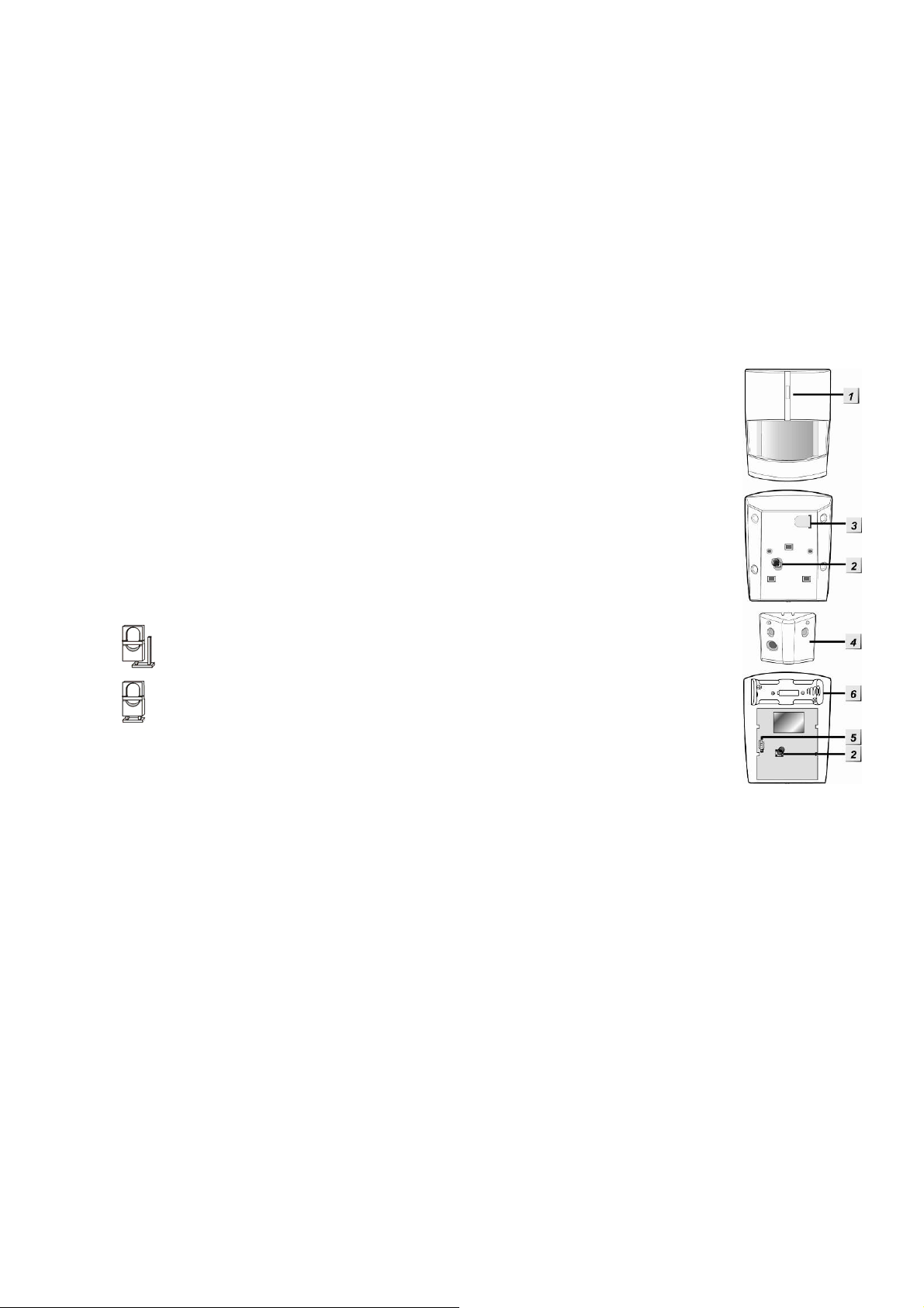
IIddeennttiiffyyiinngg tthhee ppaarrttss..
11.. FFuunnccttiioonn BBuuttttoonn//LLEEDD iinnddiiccaattoorr
The Function Button is used for testing the radio performance and for adding PIR to the Z-Wave
gateway or control panel.
The LED indicator is used to indicate the status of system.
22.. TTaammppeerr SSwwiittcchh
The Tamper Switch protects the PIR from unauthorized cover opening.
33.. BBaatttteerryy IInnssuullaattoorr
44.. CCoorrnneerr mmo
55.. SSeennssiittiivviittyy IInnccrreeaasseerr JJuummppeerr SSwwiittcchh ((JJPP33))
It is a 2-pin jumper switch
- If the jumper is OFF (if the jumper link is removed or “parked” on one pin), the PIR’s
detection sensitivity is in normal level. (Factory default for IR-16SLZW)
- If the jumper is ON (if the jumper link connects the two pins), the PIR’s detection
sensitivity is high. (Factory default for IRP-16SLZW)
66.. BBaatttteerryy CCoommppaarrttmmeenntt
z
z
SSlleeeepp TTiimmeerr
The PIR has a “sleep time” of approximately 1 minute to conserve po wer. After transmitting a detected movement, the
PIR will not retransmit for 1 minute. Any further movement detected during this sleep period will extend the sleep time b y
another minute. In this way continuous movement in front of a PIR will not unduly exhaust the battery.
ouunnttiinngg bbrraacckkeett
z
z
SSuuppeerrvviissiioonn FFuunnccttiioonn
This function uses the Z-Wave Wake Up Command Class. The Wake Up Command Class allows the battery-powered PIR
to notify the Control Panel/Gateway that it is awake and ready to receive any queued commands. The wake up interval
time period is programmed automatically according to Control Panel’s setting when The PIR is included. The
recommended setting of the interval time is between 30 to 60 minutes.
z
z
SSeennssiittiivviittyy IInnccrreeaasseerr FFuunnccttiioonn
You can use the sensitivity increaser function to increas e the IR’s detection sensitivity. To increase detection sensitivity,
please enable the Jumper to ON position. To maintain the normal detection sensitivity, enable the Jumper to OFF position
z
z
TTeesstt mmooddee
The PIR can be put into Test mode by pressing the Function Button. During Test mode, sleep timer is disabled and will
enable the LED indicator to flash every time a movement is detected.
Each time the Function Button is pressed the PIR will transmit a test signal to the Control Panel for radio range test and
enter the test mode for 3 minutes. It will exit Test Mode automatically after 3 minutes and returns to normal mode.
z
z
LLEEDD IInnddiiccaattoorr
The LED Indicator lights up in the following situations:
z When movement is detected under low battery condition.
z When the tamper switch is triggered.
z When movement is detected while the Tamper condition persists.
z When movement is detected under Test mode
Page 2
z When the Function Button is pressed under tamper condition, test mode, or if PIR is under low battery condition.
z
z
BBaatttteerryy
z The PIR uses one 3V Lithium battery as its power source. A low battery signal will be sent to the Control Panel
z The PIR will report its battery percentage to the Control Panel respectively at 100%, 75%, 50%, 25%. If the battery
z The battery is pre-inserted by the factory before shipment with a battery insulator inserted.
<<NNOOTTEE>>
along with regular signal transmissions for the Control Panel to display the status accordingly.
voltage is low (25%), a Low Battery signal will be sent to the Control Panel to notify the user.
) When changing battery, after removing the old battery, press the Tamper Switch twice to fully
discharge before inserting new battery.
z
z
AAddddiinngg DDeevviiccee ((IInncclluussiioonn))
This product can be included and operated in any Z-Wave network with other Z-Wave certified devices from other
manufactures and/or other applications. All non-battery operated nodes within the net work will act as repeaters regardless
of vendor to increase reliability of the network.
z Pull out the battery Insulator steadily.
z The LED indicator will flash for 30 seconds (The PIR is warming up). During the warm up period, the P IR will not be
activated. It is recommended that you stay away from the detection area during this time. After the warming period is
over, the LED will turn off and the PIR will be ready for operation.
z Put the Z-wave control panel into Inclusion mode (please refer to the Z-wave control panel manual).
z Within 1.5 seconds, press the Function Button 3 times.
z Refer to the operation manual of the Z-wave gateway or control panel to complete the adding process.
z Please press and release the Tamper Switch once after inclusion is completed to ensure the Gateway/Control Panel
recognizes the current Tamper condition.
z If the device has already been added (included) into another Z-wave Gateway/Control Panel, or if the device is
unable to be added into the current Z-wave Gateway/Control Panel, try removing it first (see Removing Device).
z
z
RReemmoovviinngg DDeevviiccee ((EExxcclluussiioonn))
The device must be removed from existing Z-wave network before being added into another.
Exclusion Mode
z Put the Z-wave gateway or control panel into Exclusion mode (please refer to the Z-wave or control panel manual).
z Within 1.5 seconds, press the Function Button 3 times and the device will be removed from the Z-wave network.
Factory Reset
Factory resetting the device will restore it to factory default settings (i.e. n ot included into any Z-wave network). Please only
use this procedure if the Z-Wave gateway or control panel is lost or otherwise inoperable.
z Press and hold the Function Button of the device for 12 seconds to factory reset.
z
z
RRaannggee TTeesstt
To test whether the device is able to communicate with the Z-wave gateway or control panel:
z Put the gateway / panel into range test mode (Walk Test).
z Press the Function Button on the device
z The gateway / panel should display if the device is within th e operation range (pleas e refer to the operation manual
of the gateway / panel).
z
z
ZZ--wwaavvee SSlleeeepp MMooddee
z The PIR will enter Z-wave Sleep mode (to conserve power) after waking up for a short period of time (~10 seconds).
While in Z-wave sleep mode, Z-wave gateways or control panels are unable to send commands to the PIR.
z To program the PIR using the Z-wave Gateway/Control Panel, please send command(s) to the PIR within the
wake-up period.
z
z
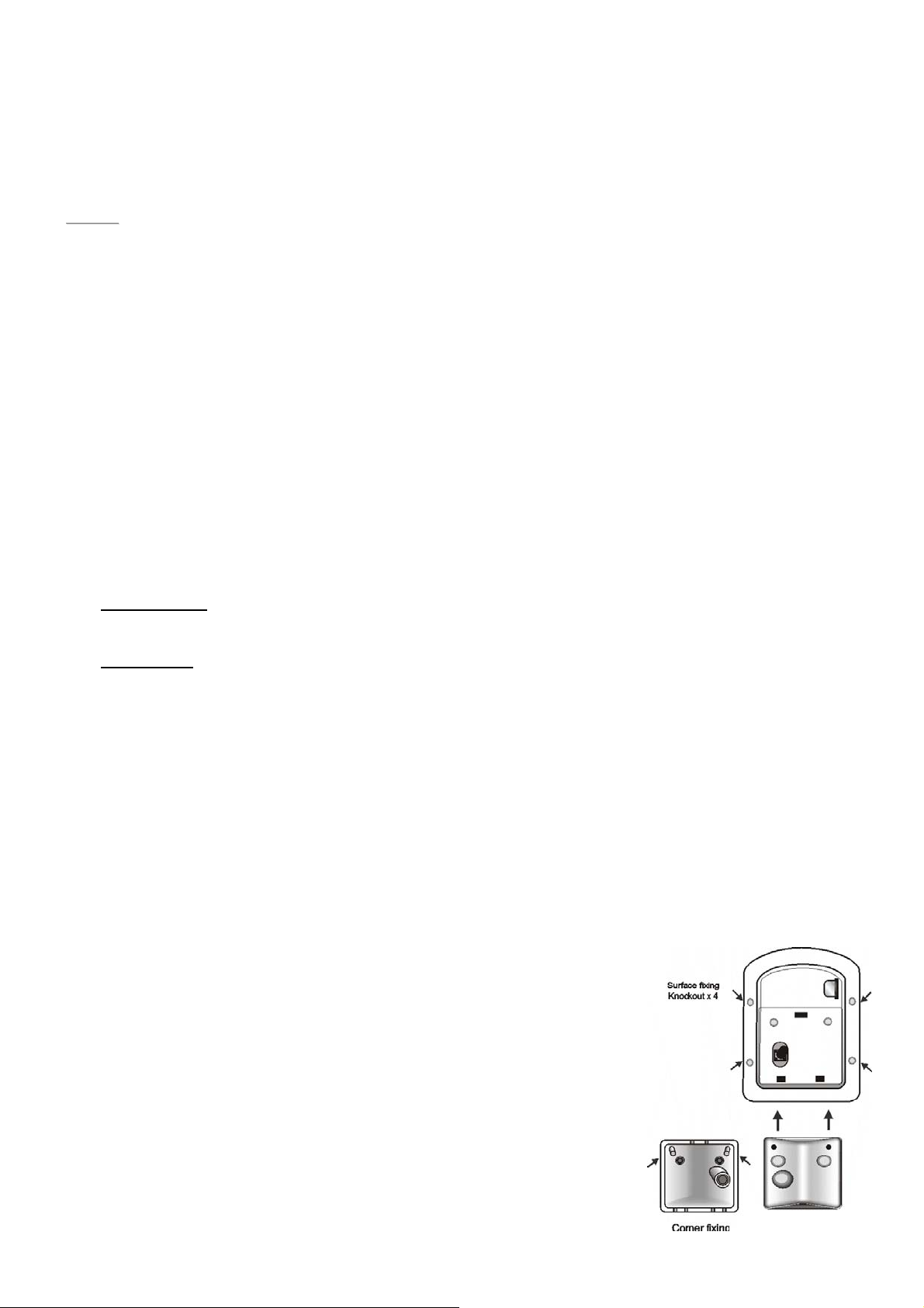
MMoouunnttiinngg MMeetthhoodd
z The PIR is designed to be mounted on either a flat surface or in a corner situation
with fixing screws and plugs provided.
z The base has knockouts, where the plastic is thinner, for mounting purpose. Four
knockouts are for surface fixing.
z For corner mounting, an optional triangular bracket is provided to add Back Tamper
Protection. Mount the triangular bracket on the wall first with the two pointing stick s
on top facing you. Fit the PIR onto the hooks of the triangular bracket or screw the
PIR onto it.
z Surface mounting:
I. Remove the fixing screw and cover assembly.
II. Break through the appropriate knockouts on the base.
III. Using the holes as a template, drill holes in the surface.
IV. Insert the wall plugs if fixing it into plaster or brick.
V. Screw the base into the wall plugs.
Page 3

VI. Replace the cover back onto the base and secure it by tightening the fixing screw.
z Corner mounting:
I. Break through the two knockouts on the triangular bracket.
II. Using the two holes as a template, drill holes in the surface of the corner.
III. Insert the wall plugs.
IV. Screw the triangular bracket into the wall plugs with the two pointing sticks on top facing you.
V. Fit the PIR onto the hooks of the triangular bracket.
VI. If necessary, open the PIR by removing the fixing screw and cover assembly.
VII. Break through the appropriate corner fixing knockouts.
VIII. Using the corner fixing knockouts as a template, drill holes in the surface in the corner again.
IX. Insert the wall plugs if fixi ng it into plaster or brick.
X. Screw the base into the wall plugs.
XI. Replace the cover back onto the base and secure it by tightening the fixing screw.
z
z
IInnssttaallllaattiioonn RReeccoommmmeennddaattiioonnss
The PIR is designed to give a typical detection range of 12 meters when
mounted at 2 meters above ground. The pet-immune model also have 7
meters of pet-immune range.
To take full advantage of PIR, the following guidelines should be considered:
It is recommended to install the PIR in the following locations
z Mount the detector at 1.9M-2.0M height for best performance.
z Mount where the animals cannot come to the detection area by
climbing on furniture or other objects.
z Don’t aim the detector at stairways the animals can climb on.
z In a position such that an intruder would normally move across the PIR’s field of view from side to side.
z In a corner to give the widest view.
z Where its field of view will not be obstructed e.g. by curtains, ornaments etc.
Limitations
z Do not position a PIR to look directly at a door protected by a Door Contact, this could cause the Door Contact
and PIR radio signals to be transmitted at the same instant when entering, canceling each other out.
z Do not install the PIR completely exposed to direct sunlight.
z Avoid installing the PIR in areas where devices may cause rapid change of temperature i n the detection area, i.e.
air conditioner, heaters, etc.
z Avoid large obstacles in the detection area.
z Not pointing directly at sources of heat e.g. fires or boilers, and not above radiators.
z Avoid moving objects in the detection area i.e. curtain, wall hanging etc.
z
z
ZZ--WWaavvee IInnffoorrmmaattiioonn
Device Type: Sensor - Notification
Role Type: Reporting Sleeping Slave (RSS)
Command Class Support/Control
Mandatory CC Support: Association CC, v2 or newer
Association Group Information CC
Battery CC
Device Reset Locally CC
Manufacturer Specific CC
Notification CC
Powerlevel CC
Version CC, v2 or newer
Wake UP CC
Z-Wave Plus Info CC
z
z
ZZ--WWaavvee’’ss GGrroouuppss ((AAssssoocciiaattiioonn CCoommmmaanndd CCllaassss VVeerrssiioonn 22))
The PIR can be set to send reports to associated Z-Wave devices. It supports 3 association groups with five node each.
Group 1 for “LifeLine”:
Notification CC,V4 (COMMAND_CLASS_NOTIFICATION)
Battery CC (COMMAND_CLASS_BASIC)
Device Reset Locally CC
Group 2 for “Basic Set”:
Basic CC, v2 (COMMAND_CLASS_BASIC)
Group 3 for “Notification Report”:
Page 4

Notification CC,V4 (COMMAND_CLASS_NOTIFICATION)
z Trigger Report (movement detected)
1. When the PIR is triggered, it will transmit Notification command to all nodes in Group1 and 3, and Basic set
(0xFF) commands to the nodes in Group 2.
z Restore Report
2. One minute after the trigger, the PIR will transmit Notification restore command to all nodes in Group1 and 3, and
Basic restore (0x00) command to the nodes in Group 2.
z Tamper Report
1. When the Tamper is removed and triggered, it will transmit Notification command (Notification Type:0x06,
Event:0x03) to all nodes in Group 1 and 3.
2. When the Tamper is restored, it will transmit Notification command (Notification Type:0x06, Event 0x00 with one
parameter 0x03) to all nodes in Group 1 and 3.
z Low Battery Report
1. When low battery voltage is detected, the PIR will transmit Battery command to all nodes in Group 1.
2. W hen PIR on low battery has its battery replaced, it will transmit Battery restore command to all nodes in Group 1
z Factory Reset
1. When the PIR is reset to factory default, it will send Device Reset Locally to all nodes in Group 1.
Federal Communication Commission Interference Statement
This equipment has been tested and found to comply with the limits for a Class B digital device, pursuant to Part 15
of the FCC Rules. These limits are designed to provide reasonable protection against harmful interference in a
residential installation.
This equipment generates, uses and can radiate radio frequency energy and, if not installed and used in accordance
with the instructions, may cause harmful interference to radio communications. However, there is no guarantee that
interference will not occur in a particular installation. If this equipment does cause harmful interference to radio or
television reception, which can be determined by turning the equipment off and on, the user is encouraged to try to
correct the interference by one of the following measures:
. Reorient or relocate the receiving antenna.
. Increase the separation between the equipment and receiver.
. Connect the equipment into an outlet on a circuit different from that to which the receiver is connected.
. Consult the dealer or an experienced radio/TV technician for help.
FCC Caution
responsible for compliance could void the user's authority to operate this equipment. (Example - use only shielded
interface cables when connecting to computer or peripheral devices).
: To assure continued compliance, any changes or modifications not expressly approved by the party
FCC Radiation Exposure Statement
This equipment complies with FCC RF radiation exposure limits set forth for an uncontrolled environment.
This transmitter must not be co-located or operating in conjunction with any other antenna or transmitter.
This device complies with Part 15 of the FCC Rules. Operation is subject to the following two conditions:
(1) This device may not cause harmful interference, and
(2) This device must accept any interference received, including interference that may cause undesired operation.
 Loading...