

Page 1
Jun-22-2015
Page 2

TableofContents
1. INTRODUCTION_________________________________________________________________________ 1
2. PANEL INFORMATION ___________________________________________________________________ 2
2.1. IDENTIFYING THE PARTS: ____________________________________________________________________ 2
2.2. THE POWER SUPPLY: _______________________________________________________________________ 3
2.3. SYSTEM REQUIREMENTS:____________________________________________________________________ 3
3. GETTING STARTED______________________________________________________________________ 4
3.1. SYSTEM DEPLOYMENT______________________________________________________________________ 4
3.2. HARDWARE INSTALLATION __________________________________________________________________ 4
3.3. SOFTWARE INSTALLATION ___________________________________________________________________ 5
4. CONNECTION TO P ANEL WEBPAGE_______________________________________________________ 8
5. DEVICE MANAGEMENT_________________________________________________________________ 10
5.1. LEARNING ______________________________________________________________________________ 10
5.2. ADD RF DEVICE__________________________________________________________________________ 17
5.3. LEARN RULE ____________________________________________________________________________ 18
5.4. WALK TEST _____________________________________________________________________________ 20
5.5. PROGRAM SIREN _________________________________________________________________________ 21
5.6. EXCLUSION _____________________________________________________________________________ 23
5.7. Z-WAVE TOOL ___________________________________________________________________________ 24
5.8. PSS CONTROL ___________________________________________________________________________ 25
5.9. UPIC CONTROL __________________________________________________________________________ 26
5.10. SURVEILLANCE _________________________________________________________________________ 27
5.11. GROUP CONTROL ________________________________________________________________________ 28
6. PROGRAM THE SYSTEM ________________________________________________________________ 29
6.1. PANEL CONDITION ________________________________________________________________________ 29
6.2. PANEL SETTINGS _________________________________________________________________________ 32
6.3. PIN CODE ______________________________________________________________________________ 36
7. NETWORK SETTINGS ___________________________________________________________________ 37
7.1. GSM (HPGWL-2/3/5 AND HPGW-G2/3/5 ONLY) ________________________________________________ 37
7.2. NETWORK ______________________________________________________________________________ 40
7.3. UPNP__________________________________________________________________________________ 41
8. SYSTEM SETTINGS _____________________________________________________________________ 42
8.1. ADMINISTRATOR SETTING __________________________________________________________________ 42
8.2. HOME AUTOMATION ______________________________________________________________________ 43
Page 3

SCENE _________________________________________________________________________________ 48
8.3.
8.4. REPORTING _____________________________________________________________________________ 50
8.5. SMS REPORT (HPGWL-2/3/5 AND HPGW-G2/3/5 ONLY)__________________________________________ 52
8.6. VOICE REPOR T (HPGWL-3 / HPGW-G1D / HPGW-G3 ONLY)______________________________________ 53
8.7. CODE SETTINGS __________________________________________________________________________ 55
8.8. SMTP SETTING __________________________________________________________________________ 57
8.9. MEDIA UPLOAD __________________________________________________________________________ 59
8.10. POLLING_______________________________________________________________________________ 60
8.11. XMPP ________________________________________________________________________________ 61
8.12. VOIP (HPGW-G1D & HPGW-G3 ONLY) _____________________________________________________ 62
8.13. DATE & TIME ___________________________________________________________________________ 63
8.14. DYNAMIC DNS _________________________________________________________________________ 64
8.15. TEST IP _______________________________________________________________________________ 65
8.16. FIRMWARE UPGRADE _____________________________________________________________________ 66
8.17. RF FIRMWARE UPGRADE __________________________________________________________________ 67
8.18. FACTORY RESET_________________________________________________________________________ 68
8.19. BACKUP & RESTORE _____________________________________________________________________ 70
8.20. SYSTEM LOG ___________________________________________________________________________ 71
9. EVENT & HISTORY _____________________________________________________________________ 72
9.1. CAPTURED EVENTS _______________________________________________________________________ 72
9.2. REPORTED EVENTS _______________________________________________________________________ 73
9.3. EVENT LOG _____________________________________________________________________________ 74
9.4. DEVICE HISTORY _________________________________________________________________________ 75
10. SMS PROGRAMMING COMMAND ________________________________________________________ 76
11. SMS USER COMMAND __________________________________________________________________ 77
12. APPENDIX_____________________________________________________________________________ 78
12.1. CONTACT-ID PROTOCOL & FORMAT _________________________________________________________ 78
12.2. EVENT CODE ___________________________________________________________________________ 79
Page 4

1. Introduction
This section covers unpacking your IP Security System with HPGW Series IP Panel and
Security Sensors. Refer to later chapters for information on setting up and configuring the
system over the Web Page in more detail.
The advanced IP Security System with fully integrated TCP/IP technology and Ethernet
connectivity is able to take full advantage of new advances in IP Home Security and Home
Automation and multi-path signalling.
The HPGW Series include the following models:
HPGWL-1 & HPGW-G1: IP Reporting.
HPGW-G1D: IP Reporting, built-in DECT compatibility, VOIP
HPGWL-2 & HPGW-G2: IP + GSM/GPRS.
HPGWL-3 & HPGW-G3: IP + GSM/GPRS, built-in DECT compatibility, VOIP (HPGW-G3 only)
HPGWL-5 & HPGW-G5: IP + GSM/GPRS, built-in Z-wave compatibility
1
Page 5
2. Panel Information
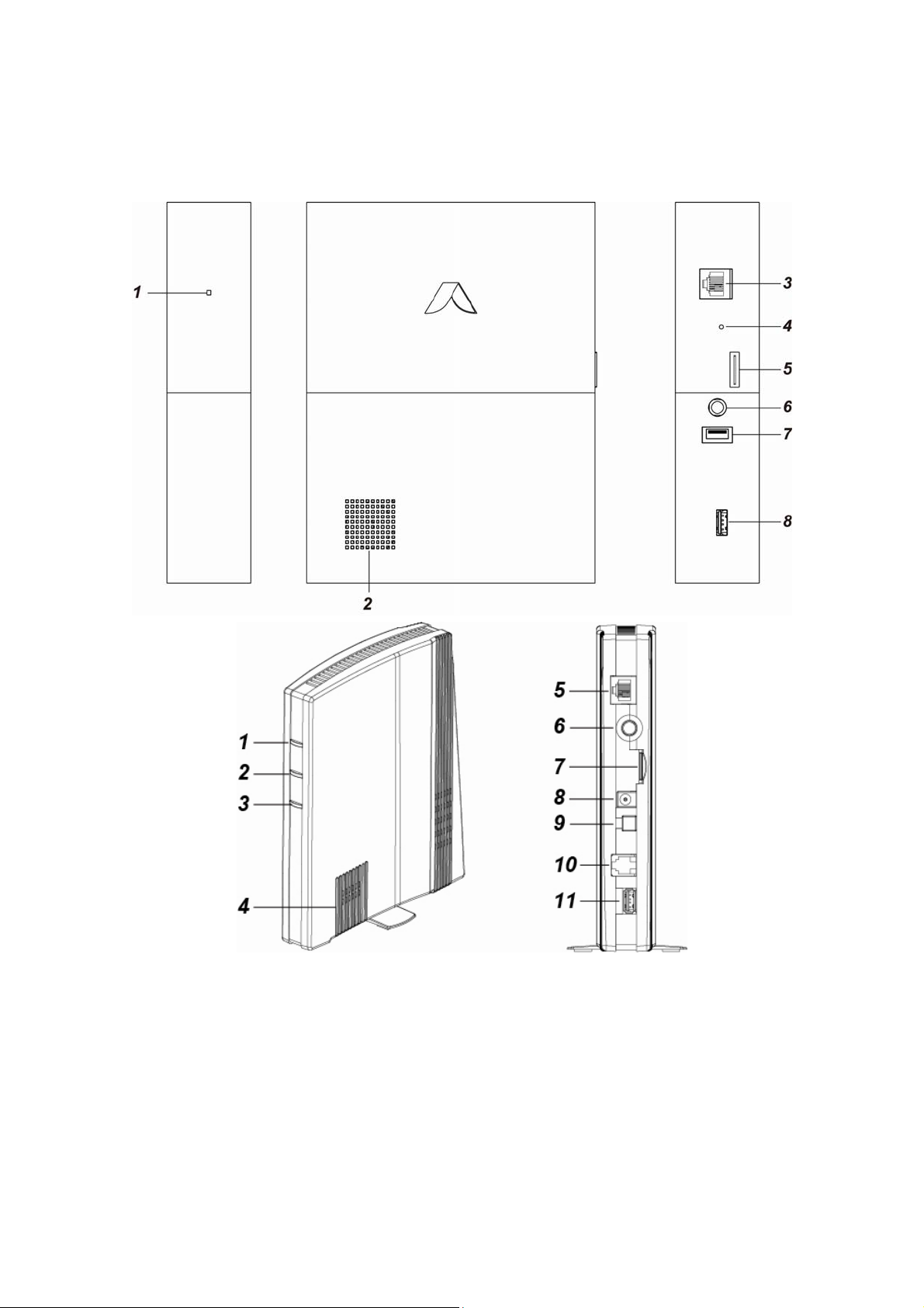
2.1. Identifying the parts:
1. System Fault/ Alarm LED (Red/Yellow)
LED 3 Red ON – Alarm in memory
LED 3 Red Flash – Alarm
LED 3 Yellow On – system fault
2. Buzzer
3. Internet Connection
4. Reset/Learn Button
5. GSM Module with SIM card Holder
2
Page 6

6. DC Jack
For connecting DC 12V 2A switching power
7. Battery Switch
8. USB Port
- Z-Wave dongle USB port
2.2. The Power Supply:
An AC power adapter is required to connect to a wall outlet. Be sure only to use an adapter with
the appropriate AC voltage rating to prevent component damage. DC 12V 2A switching power
output adaptor is generally used to power the Control Panel for standard version.
Rechargeable Battery
In addition to the adapter, there is a rechargeable battery inside the Control Panel, which
serves as a back up in case of a power failure.
During normal operation, the AC power adapter is used to supply power to the Control
Panel and at the same time recharge the battery.
<<NNOOTTEE>>
Low battery/ restore information will be displayed under the Panel section in the web
configuration page.
It takes 72 hours to fully charge the battery.
Only ZigBee and RF modules function normally
2.3. System Requirements:
The system requires a TCP/IP network environment for you to connect to the Control Panel for
system programming.
Hardware requirement for programming the panel vial LAN webpage:
Microsoft Windows 98, ME, NT4.0, 2000, XP, Windows 7 or 8operating system.
Microsoft Internet Explorer 6.x, or later and Mozilla Firefox 3.0 compatible.
CD-ROM drive
CPU: Intel Pentium II 266MHz or above
Memory: 32MB (64MB recommended)
VGA resolution: 800x600 or above
3
Page 7

3. Getting Started
Read this section of the manual to learn how to set up your Control Panel and program System
Settings over the Web page.
3.1. System Deployment
The Control Panel is designed to be wall mounted, follow guidelines below when planning
installation location:
Depend the Control Panel requires Ethernet and/or PSTN connection and may require a
SIM card depending on the model.
The Control Panel should be installed at a location that is hidden from outside view.
Avoid mounting the Control Panel near large metal objects which may affect wireless radio
strength.
The Control Panel should be protected by sensors so that no intruder can reach the Control
Panel without first activating a sensor.
When using ZigBee routers to improve ZigBee network coverage, remember to use only
ZigBee Router with backup batteries for security sensors. If you use a Router without
backup battery for security sensors, the Router will be powered down in case of AC failure,
and you security sensors will lose connection with the ZigBee network.
Home Automation devices (Power Switches…etc) do not have this limit and can be used
with any Router.
3.2. Hardware Installation
Step 1. For configuration and operation of Control Panel via Ethernet, connect the IP cable to
the RJ-45 connector.
Step 2. For HPGWG/L- /2/3/5, insert the SIM card to the SIM card holder. (Optional) Before
inserting a SIM card, please make sure the pin code is deactivated and SMS
messages are removed first.
Step 3. Connect the Power Adaptor to a Wall Outlet and the other end to the Control Panel.
After several seconds, the Control Panel will emit 2 beeps to indicate that the system
is now operational.
<<NNOOTTEE>>
Please make sure the GPRS/MMS function of GSM SIM Card is open.
If the SIM Card is changed or removed, please power off the panel then power on
again.
If a GSM fault occurs, please re-insert the SIM card and then reset the GSM in GSM
setting page.
4
Page 8
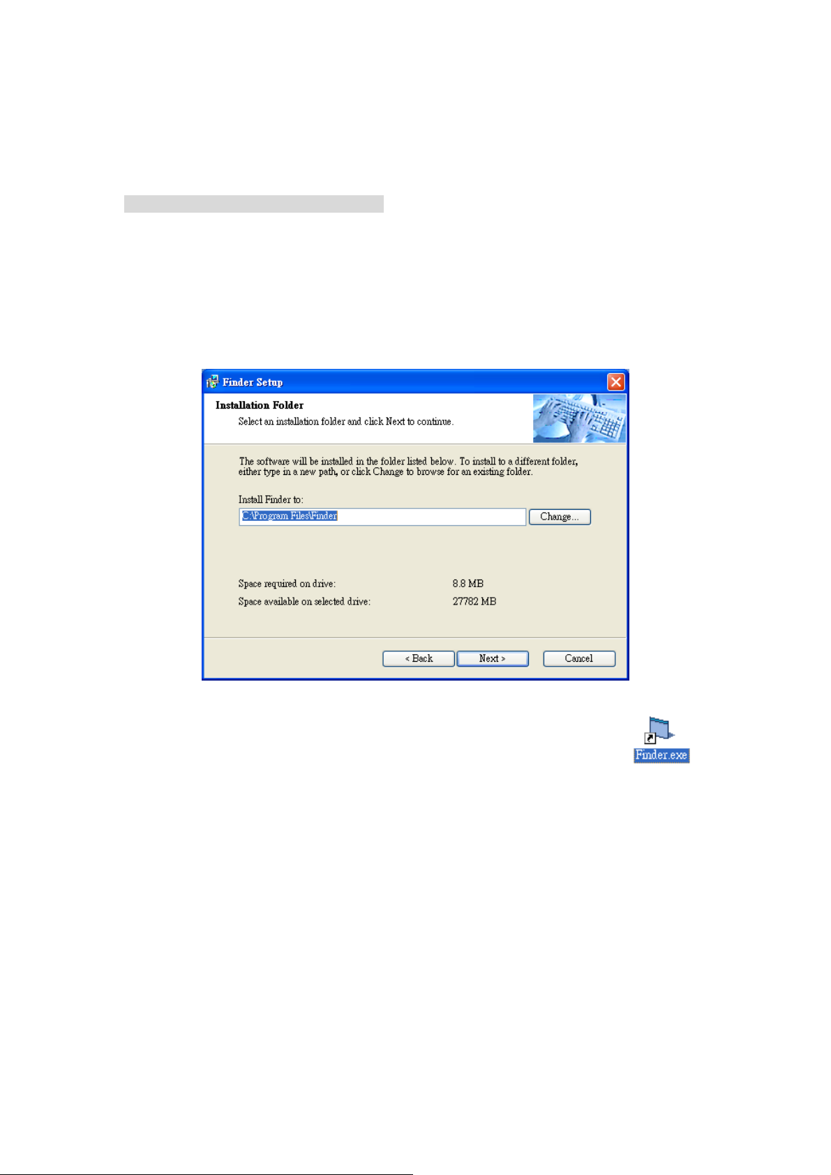
3.3. Software Installation
※ THIS INSTALLATION IS ONLY REQUIRED FOR FIRST TIME USER ※
1. RUNNING THE FINDER SOFTWARE
The Finder software is required for your computer to identify the control panel on the LAN. To
install the “Finder” software”
Step 1. Insert the supplied CD-ROM into your CD-ROM drive
Step 2. Find the Finder software in the CD-ROM.
Step 3. Double click on the Finder_v1.x to initiate the installation.
Step 4. Follow on screen instruction to complete installation
Step 5. Once complete, the Finder icon will be displayed on your desktop.
5
Page 9
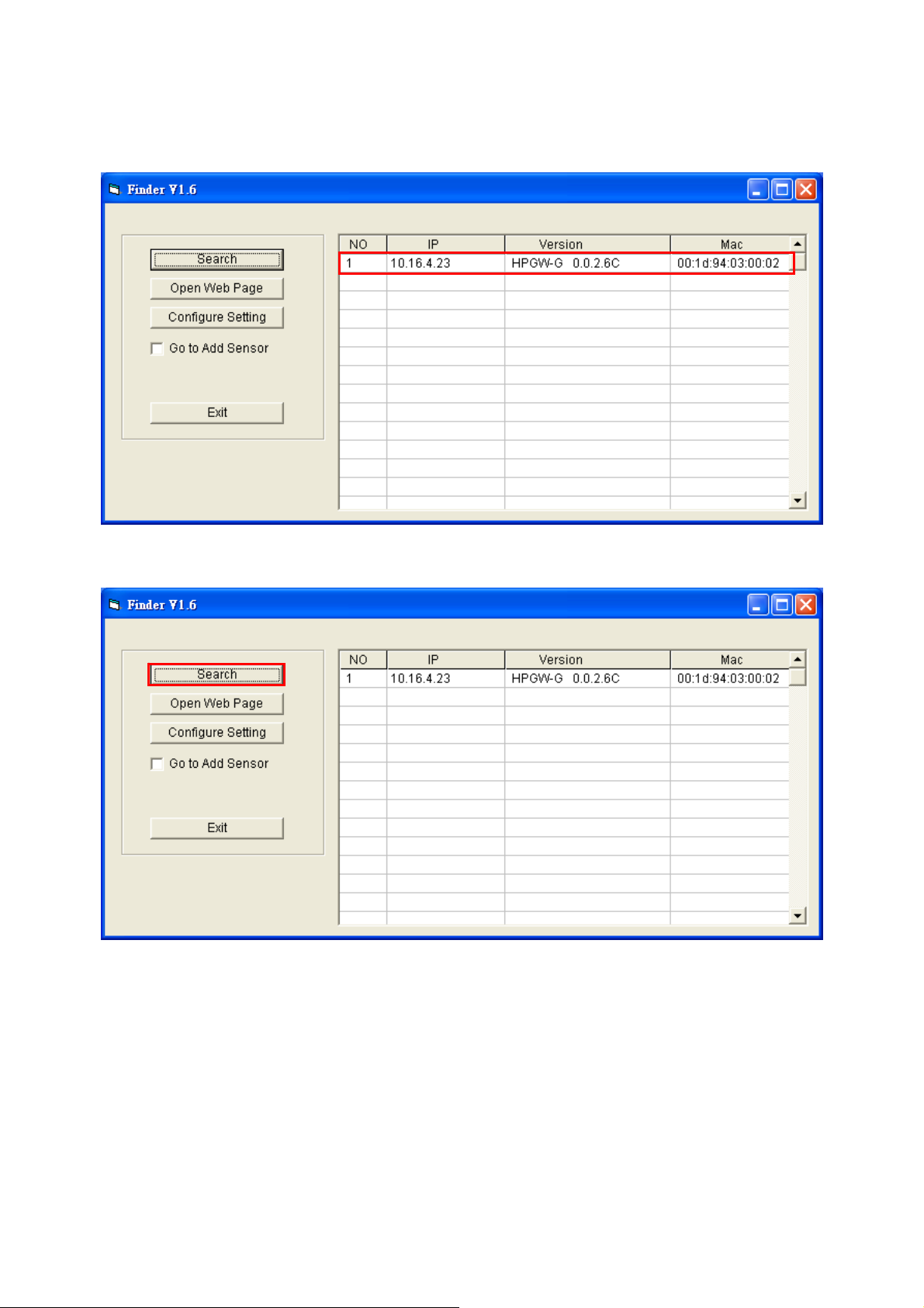
Step 6. Double click on the “Finder.exe” to start the software. Finder will automatically search
for control panel on the LAN and display its information. If available, the panel’s LAN
IP address, Firmware version and MAC address will be displayed
Step 7. If the panel information is not displayed, check panel power and Ethernet connection
and click on “Search” to update the panel information.
6
Page 10
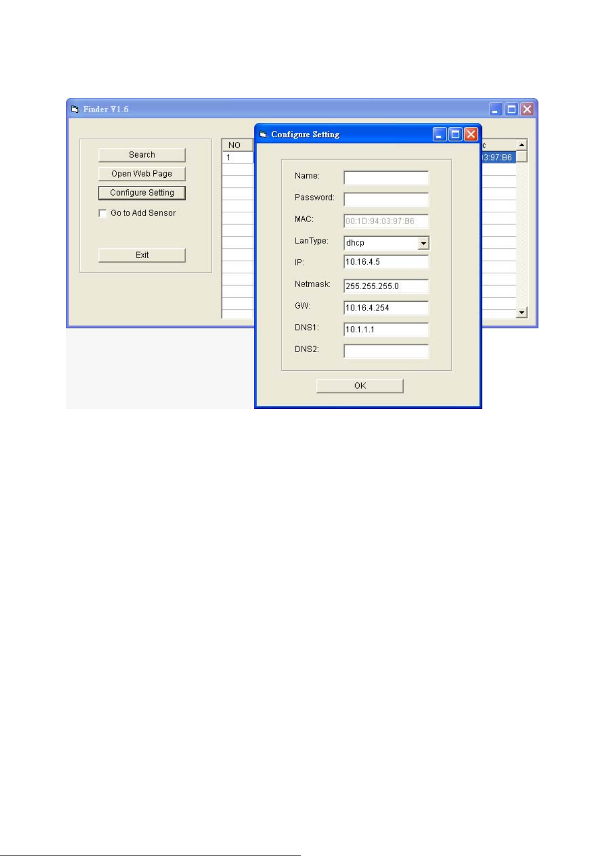
Step 8. (Optional)You can choose to edit the panel’s network setting by clicking on the panel
column, then click “Configure Setting”
The LanType is default to DHCP and does not require manual input of
IP/Netmask/Gateawy/DNS setting. If you wish to configure these setting manually,
change LanType to Static.
After finish changing network setting, enter the user name (default: admin) and
password (default:admin1234) then click OK to confirm. The user name and
password can be changed later in panel configuration webpage
Step 9. Click the panel information column and click on “Open Web Page”, or double click on
the panel column to link to the panel configuration webpage. Your default browser will
start automatically to connect to the LAN IP displayed in Finder.
7
Page 11
4. Connection to Panel Webpage
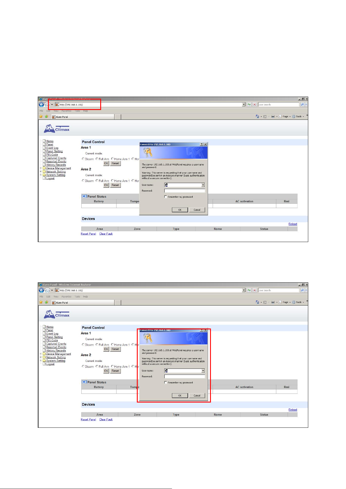
Step 1. With a valid Ethernet connection, open your browser, enter the panel’s IP address as
shown in the Finder softer under address section and click “GO” to connect to panel
webpage. Alternatively, you can also double click on the panel information in Finder
software to open the webpage.
Step 2. You will be required to enter the User name & Password.
Default User name: admin
Password: admin1234.
8
Page 12
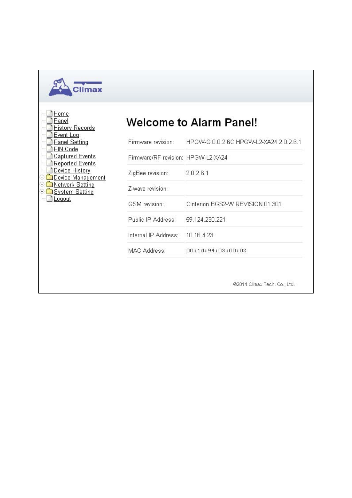
Step 3. You will enter panel Welcome page. The Control Panel’s information will be displayed.
Click on the pages and folders on the left to access the Control Panel’s various
functions.
9
Page 13
5. Device Management
The Device Management section allows you to learn in, edit, control and view all available
accessory devices that can be included in the HPGW Series Control Panel.
5.1. Learning
Use this function to add new devices into the Control Panel. HPGW Series supports up to 160
zones of accessory devices, in 2 areas, up to 80 zones each area.
The following types of accessory devices are supported:
RF device: All Climax RF devices are supported. (For ZigBee only model, RF devices are
not supported.)
ZigBee device: All ZigBee device with ZigBee Home Automation 1.2 profile are supported.
<<IIMMPPOORRTTAANNTT NNOOTTEE>>
The Control Panel built-in ZigBee module supports up to 40 ZigBee devices by itself. If
you wish to include more than 40 ZigBee devices into the Control Panel, you must add
extra ZigBee Routers into the Control Panel’s ZigBee network to increase the network’s
maximum device capacity.
IP Cameras: The Control Panel is compatible with Climax VST-1818 Series IP Camera. Up
to 6 IP Cameras are supported.
DECT Device: HPGWL-3, HPGW-G1D and HPGW-G3 only only. Up to 4 Climax DECT
device are supported.
Z-Wave Device: Available for HPGWL-5 and HPGW-G5, other models requires additional
USB Z-Wave Dongle.
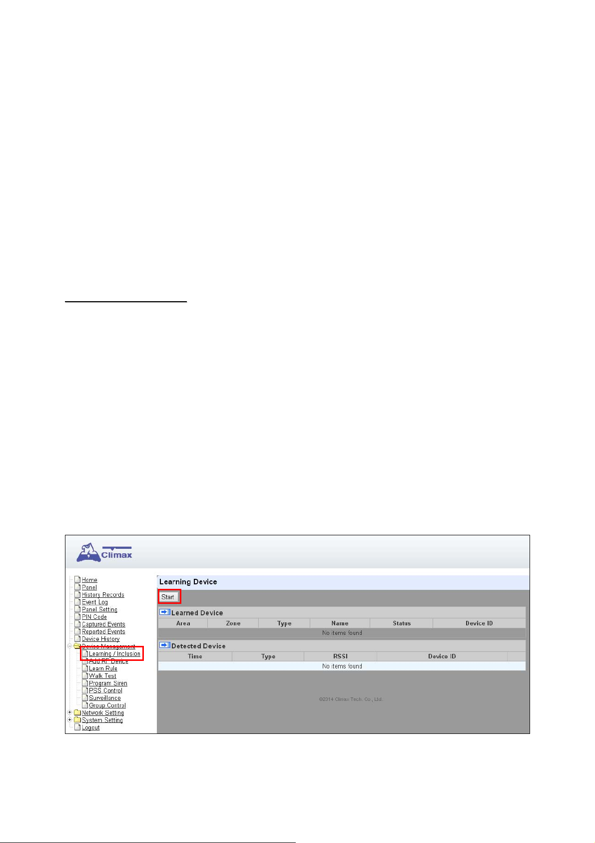
5.1.1. Add Sensor
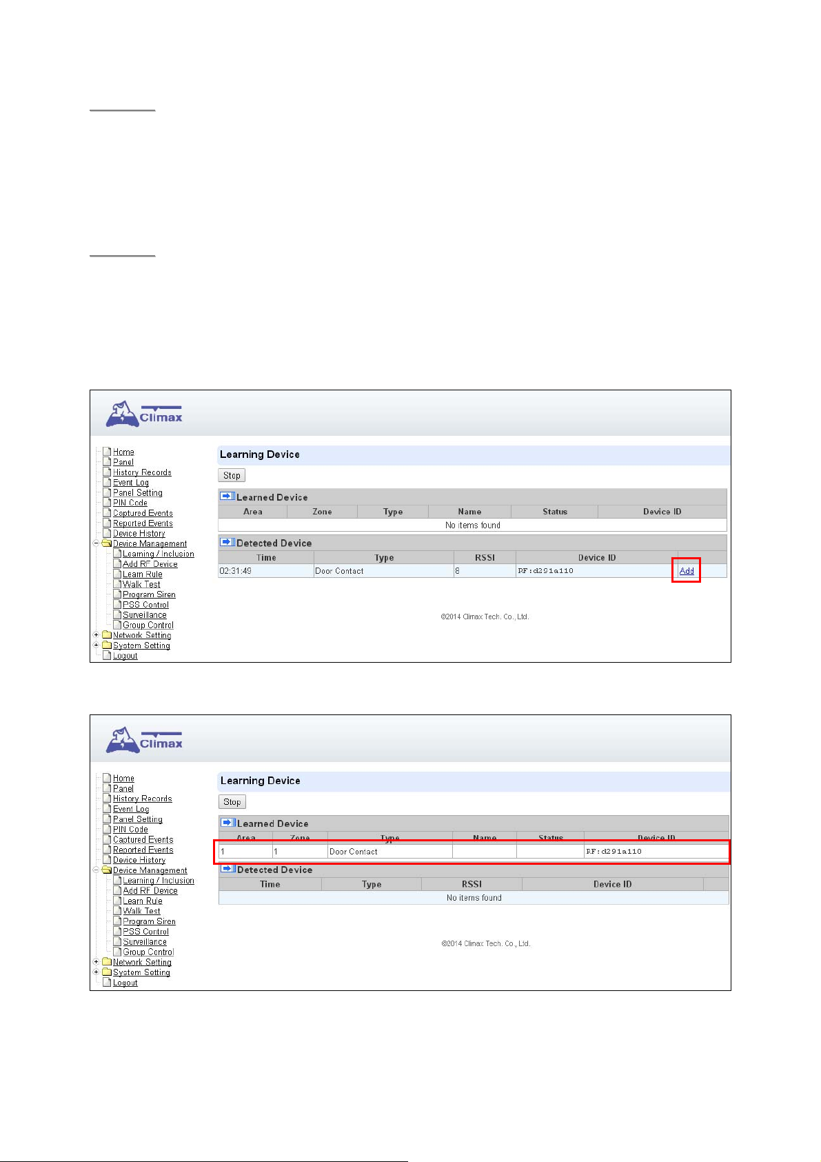
Step 1. Click on “Learning” on the tool bar and then the following screen will be displayed.
Step 2. Click on “Start” to enter learning mode.
Step 3. Press the test or learn button on the each device or any button on the Remote
Controller. (Please refer to each sensor’s user manual for test or learn button position).
10
Page 14
<<NNOOTTEE>>
Step 4. When the system received the signal transmitted from device, the screen will display its
For ZigBee sensors, press and hold the learn button for 10~12 seconds to transmit a
learn code.
For IP Camera VST-1818 Series, press and hold the Privacy button for 10 seconds.
information for selection.
<<NNOOTTEE>>
Step 5. Click “Add” to include selected device into panel. If the sensor you wish to learn into
It takes 5-10 seconds for the Control Panel to receive a learn code from ZigBee or
Z-Wave Sensor.
already exists in the system, the sensor information will be displayed in the Learned
Device section. If not, the sensor information will be displayed in the Detected Device
section.
Step 6. If the device is successfully learnt into the system, the added device will be displayed in
the “Learned Device” section.
Step 7. Repeat Step 3~5 to learn in all device, click Stop to exit learn mode when complete.
11
Page 15

5.1.2. Local Learning
Instead of learning devices via configuration webpage, you can also learn in devices by using
the learn button located on the back of Control Panel.
Step 1. Press and hold the Learn Button on the back of Control Panel for 10 seconds, release
when the Control Panel emits one short beep. LED 1 and LED 2 Green will turn ON to
indicate the Control Panel is now in learning mode
Step 2. Press the test or learn button on each device to transmit signal, refer to device manual
for detail.
Step 3. When the Control Panel receives signal from device, it will emit 2 beeps to confirm. The
device will be included in the panel automatically.
Step 4. After finish learning all devices, press and holde the Learn button for 1 second. The
Control Panel will emit 2 short beeps to indicate it has returned to normal mode. LED1
and LED 2 will dim.
<<NNOOTTEE>>
Device learnt in via Local Learning will be assigned to Area 1 only, which is limited to 80
devices.
The Control Panel cannot enter learning mode when under Away Arm/Home Arm or
Walk Test mode. The Control Panel will emit 5 beeps to indicate error.
12
Page 16
5.1.3. Edit Devices
After finish learning devices, proceed to edit the device setting.
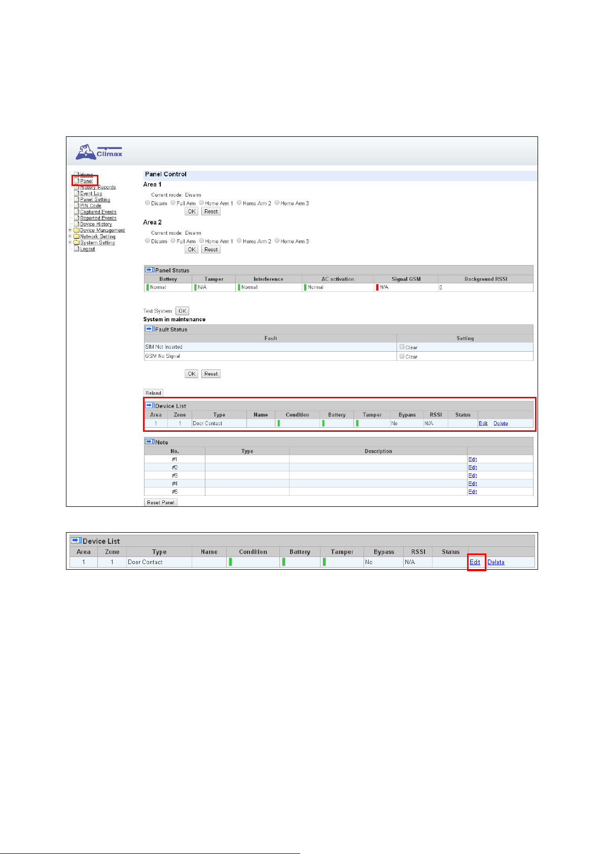
Step 1. Click Panel to enter Panel webpage. All learnt in devices will be displayed under
Device List section.
Step 1. To edit the device setting or information, click “Edit” at end of device entry.
13
Page 17
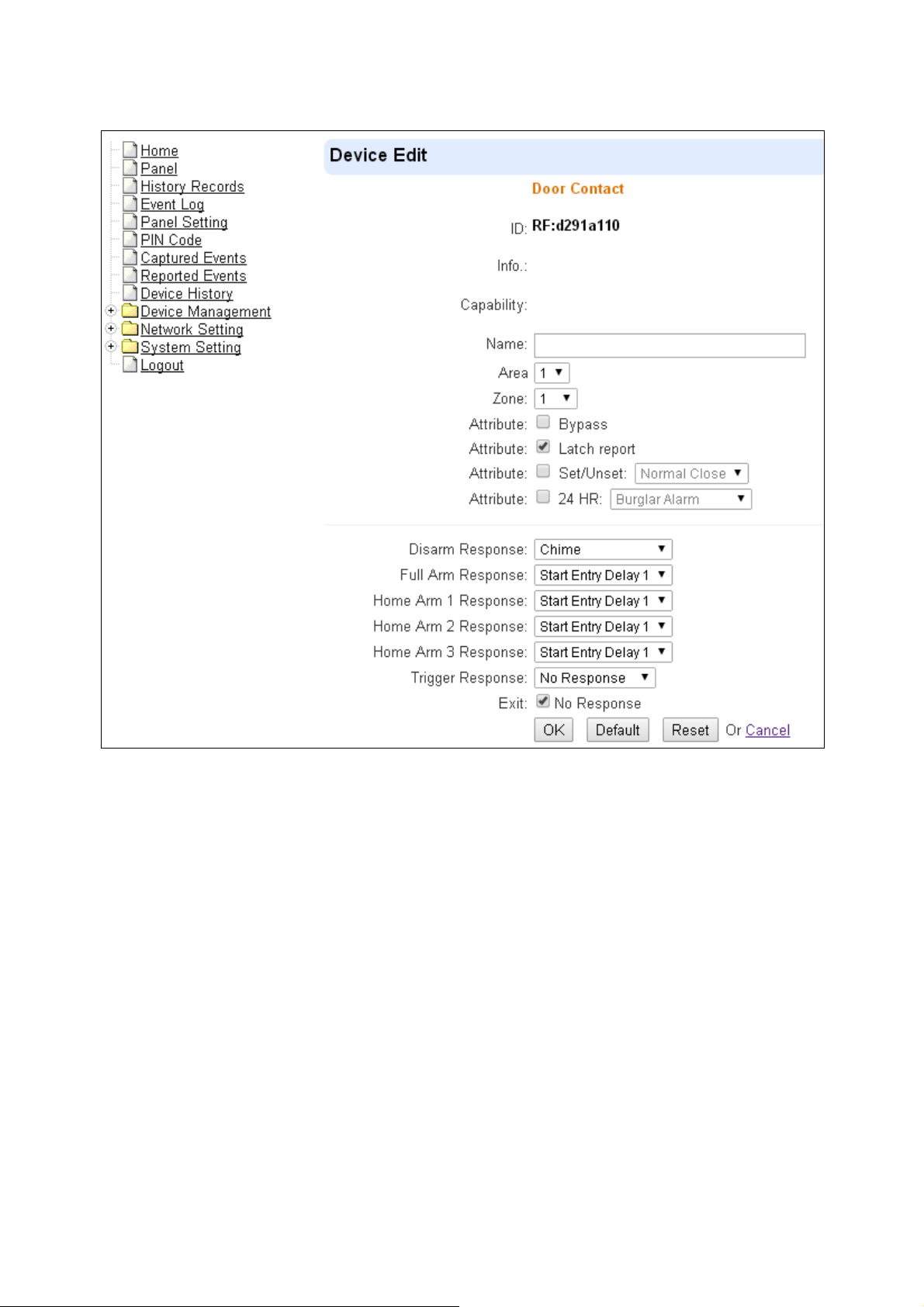
Step 2. You will enter Device Edit webpage
Step 3. Edit your device setting and information according to instruction below. Click “OK” to
save your new changes when finished. Alternatively, click “Default” to reset all
parameters to default values or click “Reset” to re-enter all the information.
Name: Enter a name for the device.
Area: Select the area which the device belongs to.
Zone: Select the Device zone number.
Bybass: this function allows user to deactivate (bypass) the selected device.
If bypassed, then the Control Panel will not respond at all when the sensor is triggered.
If bypassed, the system can be armed directly regardless the device’s fault situation.
However, its fault situation will still be monitored, logged and displayed in the history
records webpage.
Latch Report (Only for Remote Controller or Door Contact with Set/Unset attribute
enabled):
Latch Report ON = Whenever the system is armed, home armed or disarmed, the
Control Panel will report the arm/disarm event by the particular device
Latch Reprot OFF = Whenever the system is armed, home armed or disarmed, the
Control Panel will NOT report the event.
Set/Unset: For Door Contact only. This function allows Door Contact to control system
mode..
14
Page 18

Normal Close = The system will be armed when the Door Contact is opened, and
disarmed when Door Contact is closed.
Normal Open = The system will be armed when the Door Contact is closed, and
disarmed when Door Contact is open.
24H: this function enables the sensor to report an selected alarm event whenever it is
triggered regardless of system mode..
Disarm/ Full/ Home 1/ Home 2/ Home 3 response: if the system is in the disarm /
Full/home1//home2/home3 mode, when a sensor is triggered, it will respond according
to the attribute you set.
Trigger Response: When the device is triggered, the Control Panel will activated
pre-programmed scene setting. Please refer to Scene webpage for detail.
Exit: if No Response is ticked, the sensor does not repond to any trigger when the
system under Exit Delay Time 1/2. If No Response is not ticked, the sensor will raise
burglar alarm and report immediately when triggered during Exit Delay Timer.
Attribute List:
No Response
When a sensor with No Response is triggered, the Control Panel will not
respond.
Start Entry Delay 1/ Start Entry Delay 2
When the system is under Full Arm or Home Arm mode, if a sensor with Start
Entry Delay 1/2 attribute is triggered, Control Panel will start an entry countdown
period to give enough time to disarm the system.
When the Control Panel is in the Disarm mode, if a sensor with St art Entry Delay
1/2 attribute is triggered, the Control Panel will immediately report a burglar
interior alarm (CID code: 132).
When the Control Panel is in the Full Arm mode, if a sensor with Start Entry
Delay 1/2 attribute is triggered, the Entry Delay 1/2 timer starts counting down.
If no correct pin code is entered during the entry delay timer to disarm the system,
the Control Panel will report a burglar perimeter
immediately after entry delay timer 1/2 expires.
alarm (CID code:131)
When the Control Panel is in the Home Arm 1/2/3 mode, if a sensor with Start
Entry Delay 1/2 attribute is triggered, the Entry Delay 1/2 timer starts counting
down. If no correct pin code is entered during the entry delay period to disam
the system, the Control Panel will report a burglar interior
immediately after entry delay timer 1/2 expires.
alarm (CID code: 132)
Chime
When the system is in Arm/ Home Arm 1/ Home Arm 2/ Home Arm 3 mode, if a
sensor set to Chime is triggered, the Control Panel will sound a Door Chime
(Ding-Dong Sound).
Burglar Follow
When the system is in Full Arm or Home Arm mode mode, if a sensor set to
Burglar Follow is triggered, the Control Panel will report a burglar alarm
immediately.
When a St art Entry sensor is triggered and the system is under Entry Delay Timer
countdown, if a sensor set to Burglar Follow is triggered, the Control Panel will
wait until the Entry Delay Timer expires before activating a burglar alarm. If the
15
Page 19
system is disarmed before the timer expires, the Control Panel will not activate
alarm.
Burglar Instant
When the system is under Full arm or Home Arm/ Disarm / Entry Time mode, if a
sensor set to Burglar Instant is triggered, the Control Panel will report a burglar
alarm immediately.
Burglar Outdoor
When the system is in Full Arm or Home Arm / Disarm / / Entry Time mode, if a
sensor set to Burglar Outdoor is triggered, the Control Panel will report a burglar
outdoor event immediately.
Apply Scene
The attribute is for Trigger Response only. You can select a Home Automation
Scene number with this function. When the device is triggered/activated, the
Control Panel will execute the actions programming in the Scene accordingly. For
more information, please refer to 8.3. Scene.
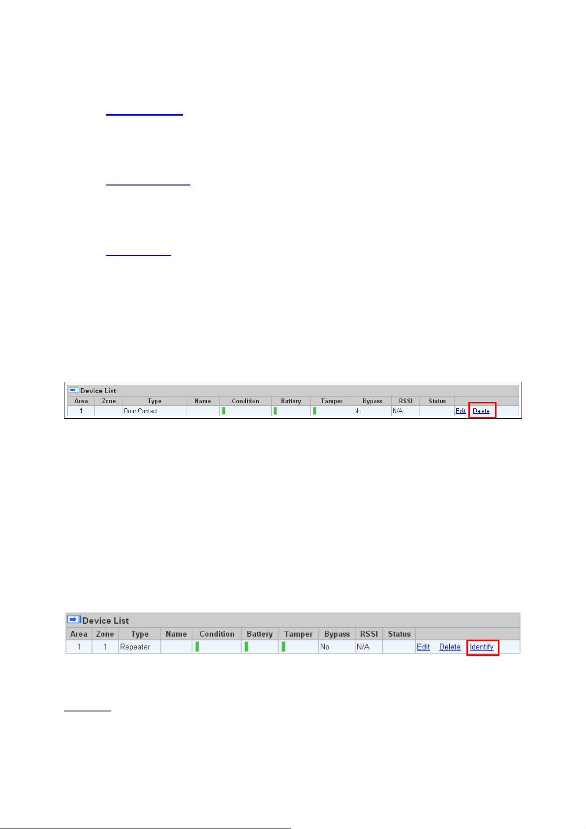
5.1.4. Delete Devices
Step 1. To delete a sensor, click “Delete” under “Device List”
Step 2. A message “Delete success” is displayed and the sensor you choose is deleted
successfully.
5.1.5. Identify ZigBee Device
The Identify function is available for ZigBee device only, it can be used to locate ZigBee devices
after learning.
For battery powered ZigBee devices, the identify fuction should be used within 1 minute after
pressing device button, or 3 minute after learning in the device. Otherwise due to ZigBee
network mechanisms, the device may not be able to receive signal successfullly from panel.
AC powered ZigBee devices do not have such limits and you can use Identify function anytime.
Step 1. Click “Identify” under the Device List after the device column entry.
Step 2. If the ZigBee device receives signal successfully, the webpage will display a success
message and the ZigBee device LED indicator will flash 10 times to confirm.
<<NNOOTTEE>>
If a timeout message is displayed on webpage, it means the device did not receive
signal from Control Panel, please check ZigBee device range from panel and make
sure to follow instruction above about Identifying battery powered ZigBee devices.
16
Page 20
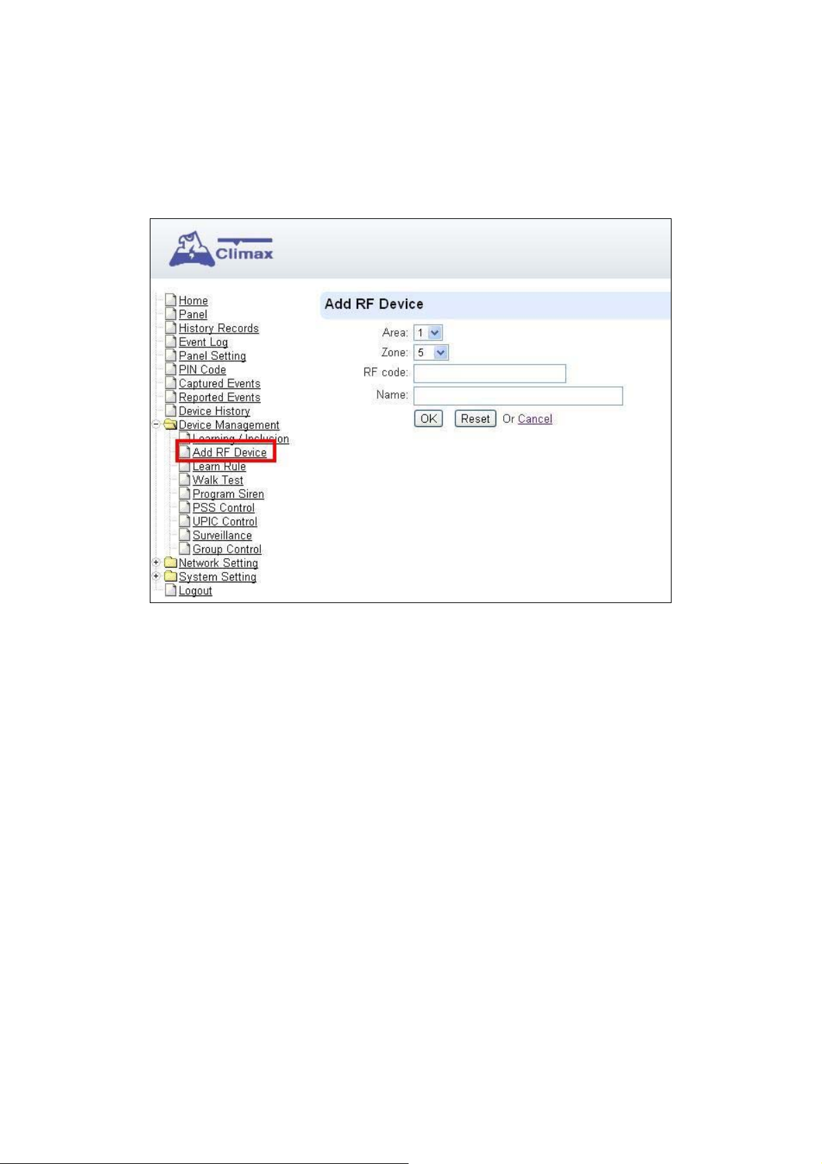
5.2. Add RF Device
Besides learning, you can also add RF devices into the system by entering its RF code into the
system with Add RF Device function.
Step 1. Click Add RF Device.
Step 2. Select Area and Zone number for the device you wish to add into system.
Step 3. Enter the device RF code, and preferred device name (up to 31 characters)
Step 4. Press “OK” to save
Step 5. If the RF code you entered is valid, the device will be added into the system according
to the Area and Zone number. You do not need to learn the device as instructed in
5.1.1. Add Sensor.
17
Page 21
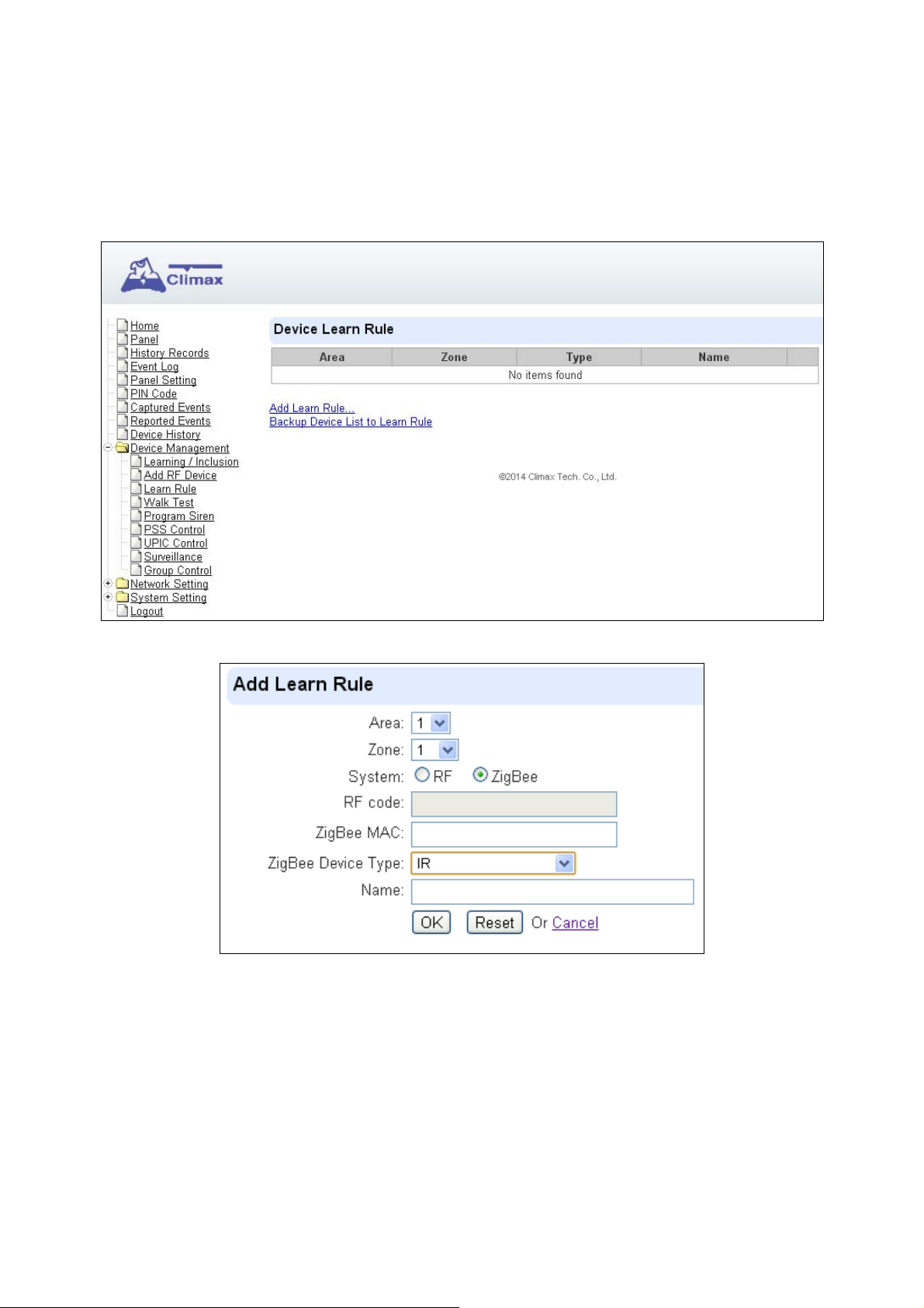
5.3. Learn Rule
You can enter the sensor RF code or ZigBee MAC address manually to assign area and zone
number to this sensor. Sensors learned with pre-assigned rule will be put under the area and
zone number you specified. This function does not work with Z-Wave devices and DECT device.
Step 1. Click Learn Rule.
Step 2. You will see the Add Learn Rule menu.
Step 3. Select Area and Zone number for this device.
Step 4. Select RF or ZigBee.
Step 5. Key in the RF code or ZigBee MAC info
Step 6. For ZigBee device, select a ZigBee Device Type
Step 7. Enter a preferred name for sensor (up to 31 letters or numbers).
Step 8. Press “OK” to save.
Step 9. If the process is successful, the screen will display “Updated Successfully.” You can
then check, edit or delete the rule under the Learn Rule menu.
Step 10 Repeat the steps to add more rules.
18
Page 22

Step 11. Learn in the sensors you have entered rules for according to 5.1.1 Add Sensor.
<<NNOOTTEE>>
Backup Device List to Learn Rule
You can choose to import learn rule from current learnt in ZigBee devices
Step 1. Click “Backup Device List to Learn Rule”.
Step 2. Click OK to confirm.
Step 3. The Learn Rule page will be updated with new rules according to current ZigBee device
Learn rule function is only used to pre-assign area and zone number to sensors before
learning. To add senor to control panel, you still need to follow the instruction in 5.1.1
Add Sensor to complete the learning process.
list information. Z-wave device and IP Camera will not be included.
19
Page 23
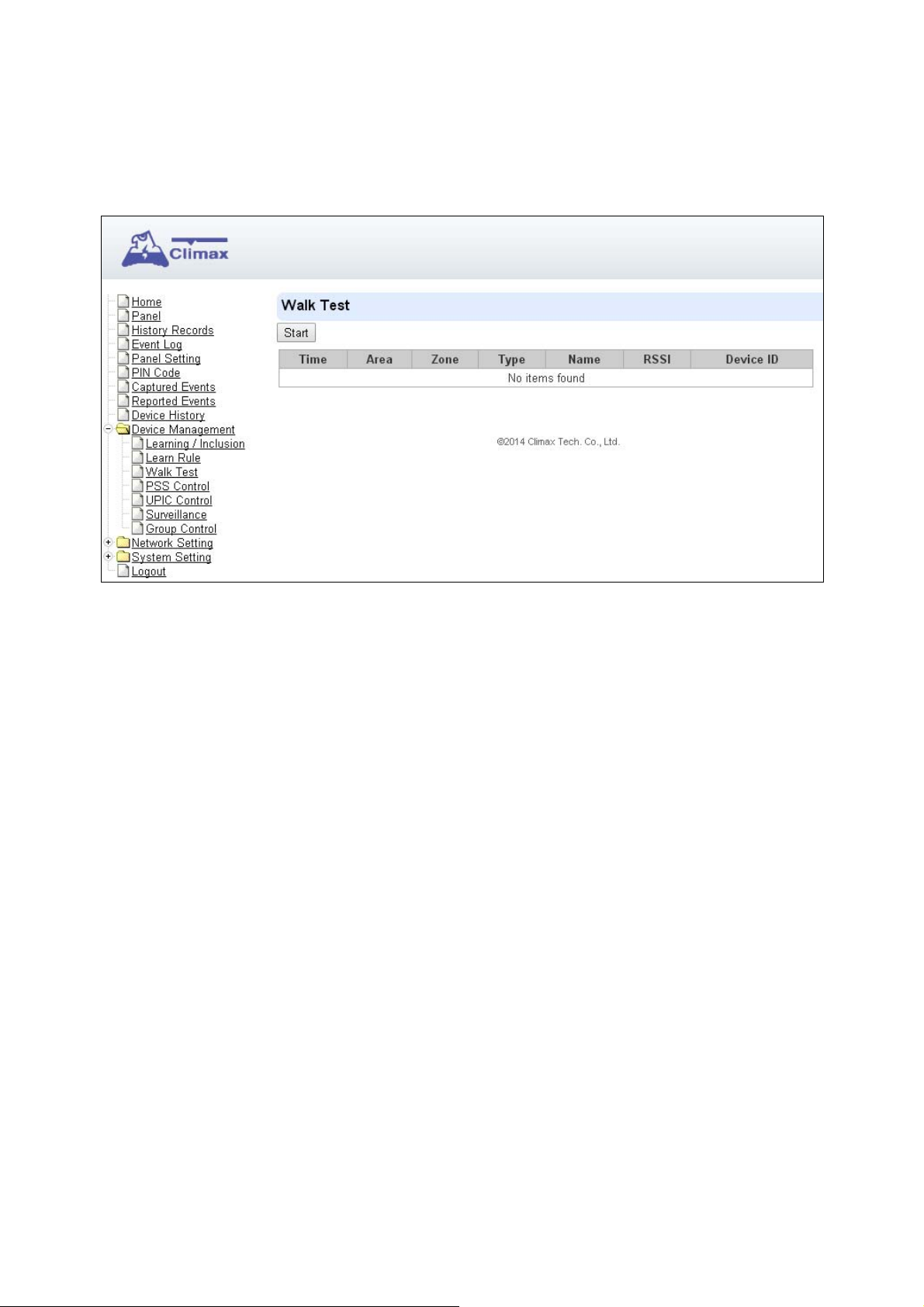
5.4. Walk Test
This is to test the sensor operation range for installation purpose.
Step 1. Click on “Start”. The Control Panel LED 1 & LED 2 Green Flash is now in Walk Test
mode. The system will automatically exit the test mode after 5 minutes
Step 2. Press the test button on the sensor(s) or any button on the Remote Controller or
triggering the sensor.
Step 3. When the Control Panel receives a signal, it will show as below and a 2-tone beep will
be heard to indicate that it is safe to install the particular sensor in the location.
Time: time informaiton
Area: operation area
Zone: device zone
Type: device type
Name: device name
Rssi: the RF signal strength between Control Panel and sensor. The Rssi value here
must be higher than the Rssi value of Panel’s background noise (please refer to 6.1
Panel Condition section for details). If not, you may still learn in the sensor; however,
please relocate the sensor and use Walk test to find a more suitable location.
DeviceID: device’s unique identification code.
Step 4. Once all sensors are tested, click on “Stop” to exit Walk Test mode.
20
Page 24

5.5. Program Siren
The Program Siren page include siren learning and setting configuration function.
Learn Siren
<<NNOOTTEE>>
Step 1. Select the Option drop-down menu, choose from All, Area1, and Area2 to determine
Step 2. Put your Bell Box or Indoor Siren in Learning Mode (Slide BX/SR dip switch 1 to ON.
The Learn Siren function is designed for single way radio siren (BX-7,8 and SR-7,8)
only. To learn in two-way sirens, please refer to the 5.1 Learning section.
which area should the siren below to.
For more details, please refer to siren manual for detail).
21
Page 25

Step 3. Click Learn Siren to transmit learn code, refer to BX/SR manual to complete learning.
Siren Setup
Siren Tamper On/Off
You can enable/disable the siren’s tamper protection with this function. Select to turn
on or off the siren’s tamper function then click “Siren Tamper” to confirm.
<<NNOOTTEE>>
When turned off, if siren tamper will be enabled again automatically af ter one hour if n ot
turn on manually during the one hour period.
Confirm On/Off
When turned on the siren will emit confirmation beep when the control panel mode is
changed. When turned off, the siren will remain silent. Select to turn on or off the
confirmation function, then click “Siren Tamper” to confirm.
Entry Sound On/Off
When turned on the siren will emit beeps during entry and exit timer. When turned off,
the siren will remain silent. Select to turn on or off the entry sound function, then click
“Siren Tamper” to confirm.
Siren Setting:
Choose to edit individual siren detail setting with the slide down menus. Refer to siren
manual for available options. After finish all settings, click “Submit” to confirm.
22
Page 26
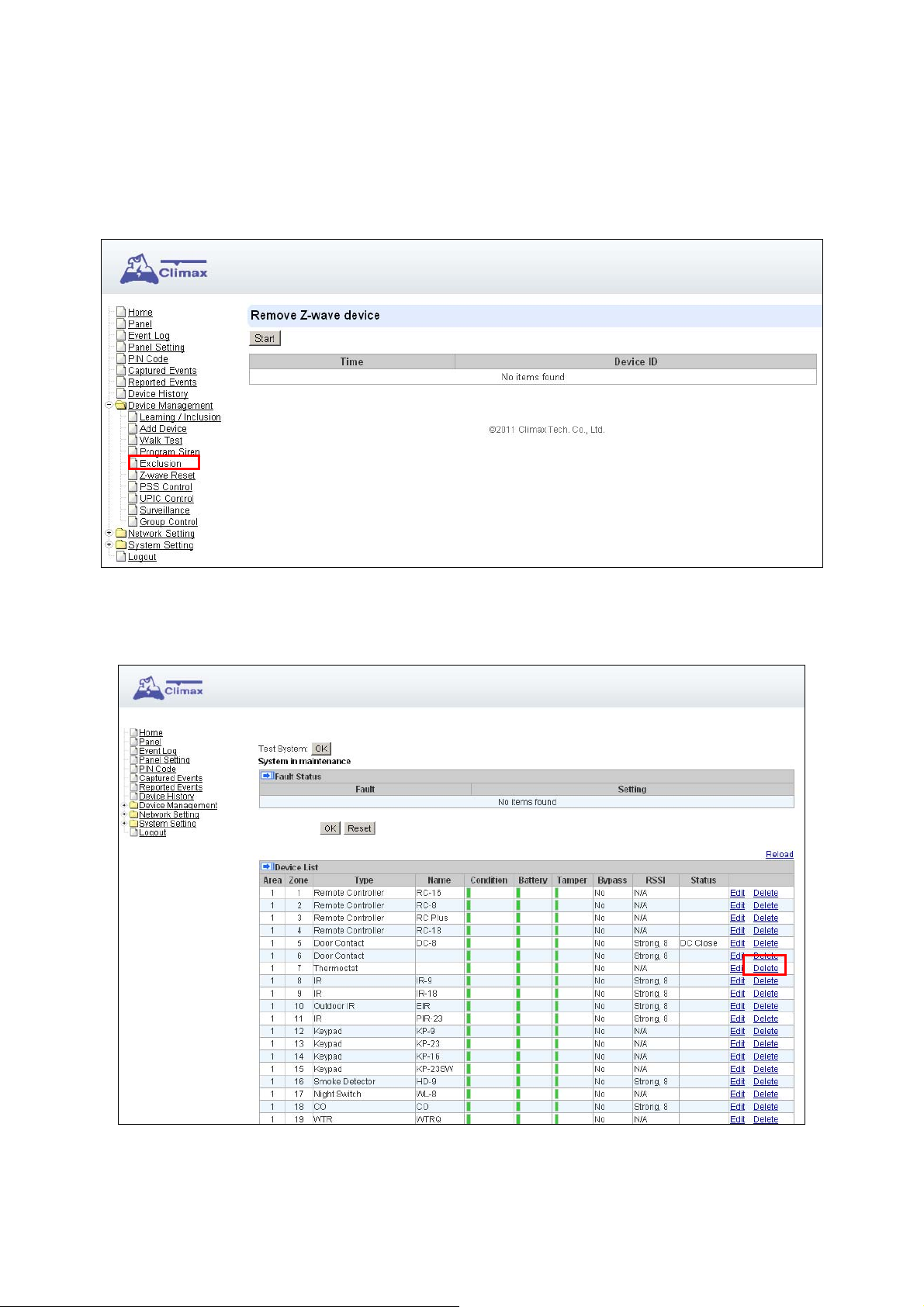
5.6. Exclusion
This feature is only available for HPGWL-5 and HPGW-G5, or when a Z-wave dongle is inserted
into the Control Panel. This feature is for you to remove Z-Wave device only.
Step 1. Click on “Exclusion” and click on “Start” to start the procedure. Then the Panel will
enter the removing mode.
Step 2. Refer to the Z-Wave device manual to transmit signal.
Step 3. Select the desired Z-Wave and click delete to remove it from the Z-wave list under
Device List section (Panel). Then the Control Panel will remove the Z-Wave device.
23
Page 27

5.7. Z-Wave Tool
This feature is only available when Z-Wave dongle is inserted. This feature is for you to reset the
Z-Wave dongle to factory default and remove all Z-Wave devices, or change routing setting.
Reset Z-Wave Dongle
Step 1. Click ”Z-Wave Factory Reset”, Then the inserted Z-Wave dongle is reset to factory
default and all Z-Wave devices will be removed automatically. The Control Panel Home
ID will also be changed automatically for a newly added Z-Wave device to recognize.
Step 2. The list of Z-Wave devices is still displayed in the Panel. Please go to Panel and then
Device List. Press Delete button to remove them one by one.
Change Z-Wave Routing Setting
Use the other functions to configure your Z-Wave routing settings.
24
Page 28

5.8. PSS Control
This feature is designed to control/edit/delete Power Switches included in the panel.
Click Edit to edit attributes of power switches.
Click Delete to remove power switch from panel.
Click Switch On/Switch Off to turn on/off power switches. Or click Switch Toggle to
toggle between on/off status. For Power Switch Dimmer, you can also set its power output
level with the slide down menu.
25
Page 29

5.9. UPIC Control
UPIC Control webpage allows you to control UPIC IR Transmitter included in Control Panel
Transmit IR Signal
Depending on the UPIC model number, select the function to be performed in the drop down
menu, then click “Setup UPIC” for the UPIC to transmit IR Signal.
UPIC5 LED Setup (UPIC5 only)
UPIC5 has 6 IR LEDs, a central one and 5 surrounding ones. The central LED will always
transmit IR signal when activated; besides the central LED, one of the 5 surrounding LEDs can
be selected to activate upon IR signal transmission to increase the IR signal coverage.
Step 1: Refer to the diagram on the webpage and UPIC5 manual to determine which LED
should be used for signal transmission to each particular home appliance.
Step 2: Select the LED number from the drop down menu for each appliance type, then click
“Setup LED” to confirm. Please refer to UPIC5 manual for more information.
<<EEXXAAMMPPLLEE>>
If “Air Conditioner” is set to LED 1, UPIC5 will transmit all Air Condition functions with
If “TV” is set to LED 5, UPIC5 will transmit all Air Condition functions with both Central
both Central LED and LED1.
LED and LED5.
26
Page 30

5.10. Surveillance
The PIR Camera/Video Cameras and IP Cameras are listed under Surveillance for separate
control.
Click Edit to edit camera attributes.
Click Delete to remove device from panel.
Click Request Media to capture a picture or vide
PIR camera: A picture will be captured upon request
PIR Video Camera: A 10-second video will be recorded upon request
IP Camera: The IP Camera will record a video according to its video length setting
(Please refer to IP Camera manual for detail.)
For PIR Camera/Video Camera, you can choose to take the picture/video without
activating the camera’s flash.
Picture and video captured by PIR Camera and PIR Video Camera will be stored under the
Captured Event webpage. Video Recorded by IP Camera will be stored in the IP Camera,
please refer to IP Camera manual to view the video
For IP Camera, click “View” or “Setting” to access IP Camera webpage for video streaming
or setting configuration. A new webpage will open and you will be required to enter the
username and password for the IP Camera to access streaming or setting.
27
Page 31

5.11. Group Control
This feature is designed for you to edit a name of group, switch on or off a group of Power
Switches. You can also assign Power Switches to groups you desire.
5.11.1. Group Control/Edit
Step 1. Specify a new name for a group.
Step 2. Click Switch On or Switch Off to turn on or off one group of power switches.
5.11.2 Device Edit/Delete
Step 1. Check on the groups you wish to assign the Power Switch. This is a multiple-choice field
and you can assign one Power Switch to multiple groups. Whenever one of the
assigned groups receives request to turn on/off, all Power Switches belonging to the
group will be activated accordingly.
Step 2. Click Edit to edit attributes of an added power switch or power switch meter or Delete to
delete this device.
28
Page 32

6. Program the System
After the initial set-up, you can then program your system by clicking on the left menu to set
them individually.
6.1. Panel Condition
In the Panel Section, user can arm, disarm or partially arm the system. Besides, it displays the
current Panel Status & Device Information.
Panel Control
Select a choice to arm, disarm or partially arm the system.
Panel Status
The Control Panel will update the panel status periodically. However, in order to show the
current status, you must reload the screen to refresh the display.
Battery: When battery is running low, a “low battery” message will be displayed to
29
Page 33

inform you to recharge the battery.
Tamper: (reserved)
Interference: This is for you to check whether the Control Panel is purposely interfered.
Whenever the signal jamming period lasts longer than 30 seconds, a “Jamming”
message will be shown and reported to the Central Monitoring Station accordingly.
AC activation: To check whether AC power is connected. If not, it will show “AC
Failure”.
Signal GSM: GSM signal value is for you to check the GSM signal strength around the
Control Panel. It ranges from 0 to 9, where 0 refers to the weakest and 9 refers to the
strongest one. The higher the value, the better the GSM signal strength.
Background RSSI: Rssi value is for you to check the RF environment around the
Control Panel. It ranges from 0 to 9, where 0 refers to the weakest and 9 refers to the
strongest background noise. Therefore, the lower the Rssi value, the better the
environment.
Test System
The function is designed to send a command to sever over the polling or XMPP protocol.
Fault Status
The fault events that exist in the alarm system is displayed under this section. When fault event
exists in system, the control panel Fault LED will light up to indicate fault status under Disarm or
Home Arm mode (The Fault LED will not light up under Arm mode).
When fault event exists, and you attempt to arm the system, the arming action will be prohibited
and the panel will display fault information on the webpage. If you still want to arm the system,
perform the arming action again to force arm.
You can check the “Clear” box in the setting column then click “OK” to ignore the fault event.
Cleared fault event will not cause the Fault LED to light up, nor prohibit arming.
Device List
1. The Control Panel will update the device information periodically. However, in order to show
the current status, you must reload the screen to refresh the display.
Area: operation area
Zone: device zone
Type: device type
Name: device title
Status: device’s current status, such as tamper status, battery status, out of order
condition or DC open. If PSM is added into the system, the data of PSM, such as
On/Off status, voltage, electric current and watt, will be displayed.
30
Page 34

2. Under Device, you could further edit or delete an added device (please refer to 5.1.3 and
5.1.4 for details). Beside, you can reset Panel settings or clear the system faults by pressing
Reset Panel.
- After pressing Reset Panel, the Control Panel will restart in 60 seconds and all configured
values will be kept without any change.
Note
The function is designed for installer to make a note for each control panel. The note you make
here can be delivered to a server over XMPP or polling protocol.
31
Page 35

6.2. Panel Settings
Program the Panel, Time and Sound Settings at your discretion.
Panel Setting
AC Fail Report: Set the waiting time before Control Panel report to Central Monitoring
Station when AC failure is detected.
AC Fail Suspend: After AC failure is detected, the panel will enter sleeping mode and
wake up at regular interval. Use this option to set the wake up period duration.
Jamming Report: this function is reserved.
Auto Check-in: this is to select whether the Control Panel needs to send check-in
32
Page 36

reporting to the Central Station automatically and to select the period of time between
check-in reports. Options available are Disable, 1 hour, 2 hours, 3 hours… up to 4
Weeks.
Auto Check-in Offset Period: This is to set the time delay before the first Auto
Check-In report is made. After power is supplied or re-supplied to the Control Panel, a
test report will be sent to the Central Monitoring Station (CMS) based on the Offset
Period. This is used to test whether the CMS is able to receive the report from the
Panel accurately.
After this test report is sent, the Control Panel will then send reports at regular interval
based on the setting of the Auto Check-in Report.
For example, if Offset Period is set to 2 Hours
hours, the Control Panel will transmit an event code 602 to the CMS after 2 hours, and
then report 602 event code periodically at a regular intervals of 12 hours.
, and Auto Check-in Report is set to 12
IR Camera Resolution of Alarm Images: This is to select the resolution and number
of pictures taken by PIR Camera when the camera detects a movement in armed
mode.
Options available are 320x240x3 images (Default), 320x240x6 images and
640x320x3 images.
Outdoor IR Camera in Greysclae: This is to select whether pictures from Outdoor PIR
Camera should be taken in greyscale instead of color pictures.
Options available are: Disable(Color Picture) and Enable (Greyscale picture)
Area Setting
Area: Select operation area to apply setting.
Final Door: If set to On: When the system is Away Armed and under exit timer
countdown, if a opened Door Contact set to Entry attribute is closed, the system will
automatically arm the system even if the exit delay timer has not expired yet.
Arm Fault Type: Select how the system should respond when it is being armed under
fault condition.
Confirm: The panel will first display a “Mode Change Fault” message and emit 2
beeps. Arming again within 10 seconds will force arm the system.
Direct Confirm: The system will be force armed directly without displaying fault
message and report an event.
Tamper Alarm: Select whether the siren should sound alarm when the tamper is
triggered.
Full Arm: when tamper is triggered under Full arm mode
local alarm and sends report to the monitoring center. While under Home Arm or
Disarm modes no alarm will be activated, nor report sent.
Always: Control Panel raises a local alarm and send report for tamper-trigger in all
modes.
, Control Panel raises a
Supervision Check: Select to enable or disable system supervision function. When
ON is selected, the Control Panel will monitor the accessory devices according to the
supervision signal received.
Time Setting
Supervision Timer: The Control Panel monitors accessory devices according to the
supervision signal transmitted regularly from the device. User this option to set a time
period for receiving supervision signals. If the Control Panel fails to receive supervision
signal from a device within this duration, it will consider the device out of order and
report the event accordingly.
33
Page 37

Entry Delay 1 for Full Arm: Set Entry Delay Timer 1 for full arm mode. When a sensor
set to Start Entry Dela y 1 is triggered under Full Arm mode, the control panel will begin
Entry Delay Timer countdown according to duration set with this option
If the Control Panel is disarmed before the Entry Delay Timer expires, the panel returns
to Disarm mode and no alarm is activated. If the Control Panel is not disarmed before
the Entry Delay Timer expires, the alarm will be activated and the panel will send report.
Entry Delay 2 for Full Arm: Set Entry Delay Timer 2 for full arm mode. When a sensor
set to Start Entry Dela y 2 is triggered under Full Arm mode, the control panel will begin
Entry Delay Timer countdown according to duration set with this option
If the Control Panel is disarmed before the Entry Delay Timer expires, the panel returns
to Disarm mode and no alarm is activated. If the Control Panel is not disarmed before
the Entry Delay Timer expires, the alarm will be activated and the panel will send report.
Exit Delay for Full Arm: Set the Exit Delay Timer when entering Full Arm mode. When
the user changes system mode to Full Arm, the panel will begin Exit Delay Timer
Countdown and enter Full Arm mode when the timer expires. The user must leave area
protected by sensors before the timer expires, otherwise an alarm will be activated with
the sensor is triggered.
Entry Delay 1 for Home Arm: Set Entry Delay Timer 1 for Home Arm mode. When a
sensor set to Start Entry Delay 1 is triggered under Home Arm mode, the control panel
will begin Entry Delay Timer countdown according to duration set with this option
If the Control Panel is disarmed before the Entry Delay Timer expires, the panel returns
to Disarm mode and no alarm is activated. If the Control Panel is not disarmed before
the Entry Delay Timer expires, the alarm will be activated and the panel will send report.
Entry Delay 2 for Home Arm: Set Entry Delay Timer 2 for Home Arm mode. When a
sensor set to Start Entry Delay 2 is triggered under Home Arm mode, the control panel
will begin Entry Delay Timer countdown according to duration set with this option
If the Control Panel is disarmed before the Entry Delay Timer expires, the panel returns
to Disarm mode and no alarm is activated. If the Control Panel is not disarmed before
the Entry Delay Timer expires, the alarm will be activated and the panel will send report.
Alarm Length: Set the duration the external siren should sound when an alarm is
activated.
Sound Setting
Door Chime Setting: this function is available only when the attribute of Door Contact
(DC) and/or PIR detector (IR) is set as Door Chime.
The Control Panel sounds a Door Chime (Ding-Dong Sound) while the DC and/or IR is
activated in Disarm / Full / Home / Entry mode.
Entry Delay Sound for Full Arm: this is for you to decide whether the Control Panel
sounds count-down beeps and volume of beep during the entry delay time in the full
arm mode.
Exit Delay Sound for Full Arm: this is for you to decide whether the Control Panel
sounds count-down beeps and volume of beep during the exit delay timer in the full arm
mode.
Entry Delay Sound for Home Arm: this is for you to decide whether the Control Panel
sounds count-down beeps and volume of beep during the entry delay time in the home
arm mode.
Exit Delay Sound for Home Arm: this is for you to decide whether the Control Panel
sounds count-down beeps and volume of beep during the exit delay timer in the home
arm mode.
Warning beep: this is for you to decide whether the Control Panel will sound a warning
34
Page 38

beep whenever a fault condition has been detected and displayed. The warning beep
will be silenced after the Fault message has been read by the user. When a new fault
condition is detected, it will then again emit a warning beep every 30 sec.
Entry/ Exit Only Final Beeps: This is for you to determine when the Control Panel
should start warning beep during Entry or Exit countdown timer. For example, if the
setting is set to 5 seconds, the Control Panel will only stat warning beep during the last
5 seconds of Entry or Exit countdown timer. When set to Disable, the Control Panel will
sound warning beep during the entire Entry or Exit countdown timer.
35
Page 39

6.3. PIN Code
The User PIN Codes are used by Remote Keypad accessory to control system mode remotely.
The 2 areas in the control panel each has 6 User PIN Codes available for setting. Each consists
of 4 digits (numeric number 0~9). User PIN code #1 for each Area is always activated factory
default.
User PIN #1 in Area 1 User PIN #1 in Area 2
Password: 1234 Password: 4321
Area
Area: Select the area for setting User PIN Code.
User Code Setting
User Code: Enter the 4-digit code in the field.
User Name: Enter a user name for easy recognition of system events. Up to 17
alphanumerical characters are allow for each user name.
Latch:
Latch Latch Report ON = Whenever the User PIN Code is used to change
system mode, the panel will report the event.
Latch Latch Report OFF = When the User PIN Code is used to change system
mode, the panel will not report the event.
Delete: Check the box if you want to delete selected user. User#1 in each area cannot
be deleted
After finish all setting, click OK to confirm change.
36
Page 40

7. Network Settings
7.1. GSM (HPGWL-2/3/5 and HPGW-G2/3/5 only)
Check SIM
This is designed for the system to check the SIM card or not. (If users do not intend to use
the GSM funciton, please tick “NO” to ensure the system will not check if the SIM card
is inserted or not and it will not display the GSM fault by LED flashing.)
GPRS
In order to allow GPRS to serve as a back-up IP Reporting method, this section will need to
be programmed before reporting.
APN (Access Point) Name
It is the name of an access point for GPRS. Please inquire your service provider for an
APN. When APN is set, the system becomes valid for internet connection.
User (GPRS)
It is the Log-in name to input before accessing the GPRS feature. Please inquire your
service provider.
37
Page 41

Password (GPRS)
It is the User Password to input before accessing the GPRS feature. Please inquire
your service provider.
<<NNOOTTEE>>
MMS
All values will be applied to both Areas 1 & 2.
The MMS settings are offered by your telecom service provider. Before configuring this
function, contact your service provider for correct MMS setting information of the inserted SIM
card.
APN (Access Point) Name
Enter a MMS APN name provided by your service provider.
User
Enter the Log-in name for accessing the MMS feature provided by your telecom
service provider.
Password
Enter the password for accessing the MMS feature provided by your telecom service
provider.
URL
Enter the MMS APN URL provided by your telecom service provider.
Proxy Address
Enter the MMS Proxy Address provided by your telecom service provider.
Proxy Port
Enter the MMS Proxy Port provided by your telecom service provider.
SMS
SMS Keyword
For sending remote commands to system via SMS message, a personalized password
is required for the Control Panel to recognize your authority.
SMS P-Word
Program Keyword is used to recognize the identity of a valid user; and to give authority
for Remote Installing (through SMS Text) or Remote Upgrading purposes (through
GPRS). This keyword will need to be inserted whenever the Remote Setting or Remote
Upgrading is required. A maximum of 15 characters is allowed.
Two Way Setting
The two-way setting is designed to adjust speaker volume and microphone sensitivity on
DECT device for two-way communication.
Send SMS Message
This feature is designed for you to send a SMS message on this web configuration page.
38
Page 42

Step 1. Click Send SMS.
Step 2. Enter a desired phone number and text message.
Reset GSM
This feature is designed for you to reset GSM module.
Step 1. Click GSM Reset.
Step 2. A pop-out message “Are you sure?” is displayed. Click Yes to confirm resetting.
39
Page 43

7.2. Network
This is for you to program the Network for IP connection.
Obtain an IP address automatically (DHCP)
If DHCP
Network DHCP Server. Therefore, manual settings are not required.
This is only to be chosen if your Network environment supports DHCP. It will automatically
generate all information.
Use following IP address
You can also enter the Network information manually for IP Address
Default Gateway
Please make sure that you have obtained all required values according to your Network
environment. Please contact your network administrator and/or internet service provider
for more information.
DNS Flush Period
You can set the system to clear current DNS resolution records for all entered URL
settings (Reporting, Upload, XMPP…etc.) after a set time period. The system will then
resolve the Domain Name again and acquire new IP address for the URL settings. This
function is disabled by default.
is selected, the Network will obtain an IP address automatically with a valid
, Subnet Mask,
, Default DNS 1 and Default DNS 2.
40
Page 44

7.3. UPnP
UPnP is Universal Plug and Play, which opens networking architecture that leverages TCP/IP
and the Web technologies to enable seamless proximity networking in addition to control and
data transfer among networked devices in the home, office, and public spaces.
Enable UPnP Device:
When enabled, you will be able to see this device via any UPnP discovery tool
Enable UPnP Port Redirect:
The device will try to find an UPnP-supported router and set up the port to redirect to the
router.
Port Forwarding:
1. Local Port
2. External Port
3. Protocol
41
Page 45

8. System Settings
8.1. Administrator Setting
It is used to set new Administrator Log-in Name and Password when accessing this web page.
Please note the Caps for your User Name and Password.
Step 1. Enter the preferred User Name.
Step 2. Enter the preferred Password in the “New Password” field and repeat the same
Password in the Repeat Password field.
42
Page 46

8.2. Home Automation
It is used to set Home Automation rules to control sensors and home appliances. You can set up
to 100 rules.
Step 1. Click on Edit.
Step 2. Select an operation area.
Step 3. Set a rule condition.
Step 4. Set a rule schedule.
Step 5. Select the corresponding action rules in the Execution field.
Area
Select an opeartion area.
Rule Condition
The rule condition determines under which circumstances the rule should be activated.
Empty : When set as Empty, the system will follow the schedule time and execution
rule to respond accordingly.
Trigger Alarm : When set as Trigger Alarm, if the specified alarm event
(Burglar/Some/Medical/Water/Silent Panic/Panic/Emergency/Fire /CO Alarm) is
triggered, the rule will be activated according to rule schedule and execution setting.
43
Page 47

Mode Change : When set as Mode Change, when the system enters specified mode,
the rule will be activated according to rule schedule and execution setting.
Mode Change and Exit Timer Stopped : When set as Mode Change and Exit Timer
Stopped, when the system changes mode to and Exit Delay Timer expires, , the rule
will be activated according to rule schedule and execution setting.
Mode Start Entry Timer : When set as Mode Start Entry Timer, when the system
begins to countdown Entry Delay, the rule will be activated according to rule schedule
and execution setting.
Temperature Below : When set as Temperature Below, if the temperature detected
by specified temperature sensor drops below set threshold, the rule will be activated
according to rule schedule and execution setting.
Temperature Above : When set as Temperature Below, if the temperature detected
by specified temperature sensor exceeds set threshold, the rule will be activated
according to rule schedule and execution setting.
Temperature Between : When set as Temperature Between, if the temperature
detected by specified temperature sensor falls within the range specified, the rule will
be activated according to rule schedule and execution setting.
High Power Consumption : When set as Power Consumption Above, if the power
output watt from a specific Power Switch exceeds, the rule will be activated according
to rule schedule and execution setting.
Humidity Above : When set as Humidity Above,if the humidity reading from specified
room sensor rises above the level specified, the rule will be activated according to rule
schedule and execution setting.
44
Page 48

Humidity Below : When set as Humidity Below,if the humidity reading from specified
room sensor falls below the level specified, the rule will be activated according to rule
schedule and execution setting.
LUX Between : When set as LUX Between, if the lux reading from specified light
sensor falls below the level specified, the rule will be activated according to rule
schedule and execution setting.
Rule Schedule
Always : When set as Always, the rule can be activated anytime.
Schedule Once : When set as Schedule Once, the system will follow the rule
condition and execute rule according to the exact date and time specifed..
Schedule Every Month : When set as Schedule Every Month, the system will follow
the rule condition and execute rule according to date and time specified every month.
Schedule Every Week : When set as Schedule Every Week, the system will follow
the rule condition and execute rule according to day of the week and time specified
every week.
Schedule Every Day : When set as Schedule Every Day, the system will follow the
the rule condition and execute rule according to time specified every day
Execution
Execution is the actual action performed by Control Panel when both Rule Condition and
Rule Schedule requirements are met
Zone Switch Off: Turn on the Power Switch at specified zone.
45
Page 49

Zone Swich On : Turn on the Power Switch at specified zone.
Zone Swich On For : Turn on the Power Switch at specified zone for a set duration.
Zone Switch Level:: Change the power output level for Dimmer at specified zone.
Zone Swich Toggle : Toggle on/off the Power Switch at specified zone.
Group Switch Off : Turn off all Power Switches assigned to specified group.
Group Switch On : Turn on all Power Switches assigned to specified group.
Group Switch On For : Turn on all Power Switches assigned to specified group for a
set duration.
Mode Change : The system will change to the mode as you specified.
Request Image : The PIR Camera in specified zone will take a picture.
Request Image (All) : All PIR Cameras in the system will take a picture.
46
Page 50

Request Image (No Flash): The PIR Camera in specified zone will take a
picture.without activating its LED flash.
Request Image (All, No Flash) : All PIR Cameras in the system will take a picture
without activating LED Flash.
Request Video : The PIR Video Camera or IP Camera in specified zone will record a
video.
Request Video (All) : All PIR Video Cameras and IP Cameras in the system will
record a video.
Setup UPIC:: The UPIC and specified zone will transmit Off/Heat/Cool command to the
air conditioner as programmed.
Trigger Alarm: Choose to activate one of the following alarms: High Temperature
Alarm, Low Temperature Alarm, High Power Consumption Alarm, High Humidity Alarm
and Low Humidity Alarm
Apply Scene:: the system will execute preprogrammed Scene number. Please refer to
8.3. Scene for detail.
47
Page 51

8.3. Scene
The Scene setting allows you to customize a series of actions with your devices, such as Power
Switch control, image/video request, mode change and trigger alarm. The programmed scene
can be set to activated when a device is triggered. (See 5.1.3. Edit Devicesl), or when a Home
Automation Rule is excecuted. (See 8.2. Home Automation) For example, you can set a scene
to control multiple lightings, then set your Remote Controller to activate the scene when the
button is pressed, or set a Home Automation Rule to activate the scene.
Step 1. Click on Edit.
Step 2. Enter a name for the scene.
Step 3. Select an Area
Step 4. Select an action to be executed when the scene is activated. Refer to the Rule
Execution section in 8.2. Home Automation for detail.
48
Page 52

Step 5. Repeat Step 2-3 to setup the execution you wanted. As many as 5 executions can be
included in one scene.
Step 6. Click “Done”.
Step 7. Click “OK” at bottom of webpage to confirm the new scene setting..
49
Page 53

8.4. Reporting
This is used for installer to program/ set all requirements for reporting purposes.
Reporting URL
This is used for installer to program/ set all requirements for reporting purposes.
Report via IP (Ethernet or GPRS) in CID format:
ip://Account Number@server ip:port/CID
Report via IP (Ethernet or GPRS) in SIA format:
ip//Account Number @server ip:port/SIA
Report via IP (Ethernet or GPRS) in CSV format:
ip//Account Number @server ip:port/CSV
Report via IP (Ethernet or GPRS) in CSV format including user name and password:
ip//Account Number @server ip:port/CSV/User/Pasword
Report via GSM CID:
gsm://Account Number@telephone number
<<NNOOTTEE>>
Account number is 4 ~ 6 digits.
Report via email (Requires SMTP setting)
mailto: user@example.com
50
Page 54

Level
Select a reporting condition:
All events
Alarm events
Status events
Group
Select a group for your report destination The system will make report according to the
following principle:
: The system will report all events to this destination.
: The system will only report alarm event to this destination.
: The system will only report status event(non-alarm events) to this
destination.
Group with higher priority will be reported first: Ex: Group 1 Group 2 Group 3….
If reporting to the first destination in a group fails, the system will move on to the next
report destination in the group.
If reporting to one of the report destinations in a group is successful, the system will
consider reporting to this group successful and stop reporting to rest of the destinations
in the group. It will then move on to report to the next group.
If reporting to all destinations in a group fails, the system will retry report to group
according to retry times set below. If reporting is still unsuccessful after retries, the
system will move on to report the the next group according to Essential/Optional setting
below.
After completing a round of reporting (From Group 1 Group 2 ….. Group5), If there
is any group set as Essential which has not received report successfully, the system
will restart the reporting cycle to retry reporting until every group set as Essential is
reported successfully.
Essential/Optional
Essential: the system will report to all groups set as Essential. The system will never give
up trying to report to any group set as Essential until at least one of the
destinations in every Essential group successfully receives the report. Group 1
is always set as Essential and cannot be changed.
Optional: The system will only report to group set as Optional when reporting to its
previous group fails. For example: if Group 3 is set is optional, the Control Panel
will only report to Group 3 if reporting to Group 2 fails.
1 Retry/ 3 Retry/ 5 Retry/ 10 Retry/ 99 Retry:
If reporting to all destinations in a group fails, the system will retry reporting to the group
according to the retries times set here.
<<NNOOTTEE>>
When the panel is registered into Climax’s Home Portal Server, URL1 will be filled in
After registering the panel in Home Portal Server, if you wish to set more reporting
with Home Portal Server report information. Do not change the information once
registration is complete or reporting to Home Portal Server may encounter error.
destination, the new report destination should be set to different group than URL1
otherwise it may not be able to receive report successfully.
51
Page 55

8.5. SMS Report (HPGWL-2/3/5 and HPGW-G2/3/5 only)
This is used for setting SMS reporting .
Reporting URL
Set the SMS report destiation according to following format:
sms://Account Number@telephone numeber
Level
Select the event type that will be reported to this reporting destination:
All events
Alarm events
Status events
<<NNOOTTEE>>
: The system will report all events to this destination.
: The system will only report alarm event to this destination.
: The system will only report status event(non-alarm events) to this
destination.
If all functions are enabled, then only ONE function will be carried out. Priority
sequence is IP> Voice Telephone > CID reporting over GSM> Follow On> SMS
reporting > Callback Timer.
52
Page 56

8.6. Voice Report (HPGWL-3 / HPGW-G1D / HPGW-G3 Only)
Panel models with DECT device capability are able to make voice call during alarm reporting
and establish two-way voice communication with call recipient. Each two-way voice session
lasts 3 minutes. At the last 30 & 10 secs of two way conversation, the DECT device will emit 1
short beep to alert the call recipient.
The panel will make voice report after the first successful alarm reporting. At least one
report destination must be programmed to use voice reporting function.
Warning: Voice reporting is not available when AC power failure is detected.
Follow-on
Check the box to enable the Follow-on function.
If enabled, the Control Panel will open two-way communication after the first GSM CID
report
If not enabled, the Control Panel will dial the telephone number set below after the first
successful report.
53
Page 57

Telephone
Enter the telephone number in the field, if Follow-on is enabled, leave the telephone
number blank.
Callback Timer
If not disabled (set to 5 or 10 minutes). After an alarm has been reported, the panel will
enter a waiting period for callback. Incoming call during this period will be answered
automatically to open two-way communication with DECT devices. The Callback time will
end after set waiting period has expired or after the incoming call has ended.
Service Telephone
The service telephone number can only be dialed using VST-809 for non-emergency
service call.
<<NNOOTTEE>>
VOIP setting must be programmed first before the Control Panel can make report
via VOIP. Please refer to 8.12. VOIP for more information.
54
Page 58

8.7. Code Settings
The Duress Code, Master Code & Temporary Code adds the flexibility of different security level
for operation in Code Settings menu.
Step 1. Key in your preferred 4 digit Installer Code, Duress Code, Master Code, and/or
Temporary Code.
Step 2. You can also choose to have Latch Option On / Off for Temporary Code by tick the
Latch Option box and press OK to confirm the settings.
Installer Code
The Installer Code is used for SMS Remote Programming, when sending a remote
programming message, the user needs to enter Installer Code in the message to be able
to program the system. The default Installer code is: 7982.
Area
Each Area has different Duress Code, Master Code, and Temporary Code. Select the Area
to program the code setting in this area.
55
Page 59

Duress Code
The Duress Code is designed for transmitting a secret & silence alarm
When Duress Code is used for accessing the system, the Control Panel will report a
secret alarm message without sounding the siren to the Central Monitoring Station to
indicate of a Duress Situation in Progress.
The Duress Code consists of 4 digits and is not activated as default by the factory.
Guard Code
The Guard Code is designed for security patrol personnel to arm/disarm the system. It can
be set the same as a User PIN Code.
The Guard Code consists of 4 digits and is not activated as default by the factory.
Master Code
This function is currently disabled.
.
Temporary Code
Temporary Code is also used to arm/disarm the system, but it is for a temporary user. The
temporary Code is ONLY valid for one-access per arming and disarming. Afterwards, the
Temporary Code will be automatically erased and needs to be reset for a new Temporary
user.
The Temporary Code consists of 4 digits and is not activated as default by the factory.
Latch Option
This is to program the Latch Key Reporting feature for Temporary Code. Please click the
box to select the options.
Latch Latch Report ON = Whenever the system is armed, home/ day home/ night
home armed or disarmed, the Panel will transmitt Contact ID code / SMS message /
GPRS reporting (according to pre-setting) to notify the Central Monitoring Station.
Latch Latch Reprot OFF = Whenever the system is armed, home/ day home/ night
home armed or disarmed, the Panel will NOT
Monitoring Station.
transmit reporting(s) to notify the Central
Delete
Except Master Code which can’t be disabled in any way, Temporary and Duress Code can
be disabled by cleaning the code box and leaving the box as blank.
56
Page 60

8.8. SMTP Setting
Program the mail server related settings. The email account you set here would be used to send
report for events or picture and video clip captured by PIR Camera and PIR Video Camera.
Step 1. Enter the following settings:
Server: set the mail server (max. 60 digits/alphabets).
Port: set the port number (max. 5 digits/alphabets).
User: set the mail account name (max. 30 digits/alphabets).
Password: set the password corresponding to the mail account name (max. 30
digits/alphabets).
From: set the email address according to your mail sever and account name. If your mail
server supports other email address, you can enter the email address here. (max. 30
digits/alphabets).
Using TLS/SSL encrypted channels (Secure SMTP):If your mail server uses TLS or
57
Page 61

SSL encryption method for secure transfer, please click the box to enable the setting
Step 2. Click OK to confirm the setting.
58
Page 62

8.9. Media Upload
The system can deliver captured images and video clips captured by PIR Cameras and PIR
Video Camera to cell phone, email or ftp.
FTP: ftp://user.password@server/path
HTTP: http://ip:port/path
Email: mailto:user@server (transmitting an alarm image over Ethernet)
MMS via Telephone: mms: telephone number
MMS via GPRS: mms: user@mail.server (transmitting an alarm image over MMS)
<<NNOOTTEE>>
If “Deleted events after uploaded” is checked, the system will automatically clear all
captured images which are displayed in the Captured Events menu af ter it successfully
sends out those captured images to preset reporting destinations.
59
Page 63

8.10. Polling
The polling function enables the Control Panel to query the destiation you set (URL1 or URL2) in
turn as to whether it has any data to transmit.
URL/URL2: ip://server:port/path
Interval : interval time of polling
60
Page 64

8.11. XMPP
XMPP setting enables the Control Panel to query the set destination. This setting is required for
the Control Panel to connect to Climax’s Home Portal Server for remote control. If the panel is
disconnected from the server, it will retry connection every 3 minutes.
Server: server address
Port: server’s port number
User: authorized user account name
Password: authorized user password
Domain: domain address
Buddy List: contact destination
Ping Interval: server connection test interval
61
Page 65

8.12. VOIP (HPGW-G1D & HPGW-G3 Only)
Program your VOIP server setting with this page. The VOIP setting must be completed before
you can use Voice Report function via VOIP.
Server: Your VOIP server URL, factory default is set to Climax’ Home Portal Server. If you
use your own server, a SIP VOIP server is required. We recommend using an Asterisk
server.
User: Enter your username in the VOIP server
Password: Enter the password.
62
Page 66

8.13. Date & Time
Program the current Date & Time and set automatic synchronization with internet time server.
Date & Time: set current month, date and time.
Time Zone: choose your time zone, and then the system will calculate the daylight saving
time automatically (if necessary).
Internet Time: the system will automatically synchronize with an internet time server. Tick
the check box to enable this function. Available options: pool.ntp.gov
tick.usno.navy.mil
.
, time.nist.gov and
63
Page 67

8.14. Dynamic DNS
This page is used to provide you the Control Panel’s current public IP address.
Dynamic DNS Server: http://checkip.dyndns.org
64
Page 68

8.15. Test IP
This is for you to test the Control Panel internet connection.
Step 1. Enter the URL destination you want to test connection to.
Step 2. Enter the test interval.
Step 3. Click “OK”
You can check the test connect result in System Log.
65
Page 69

8.16. Firmware Upgrade
You can update the firmware via this web page.
Step 1. Click on “Browse” and locate the latest firmware file (“unzipped image.bin” file) in
your PC.
Step 2. Press “Apply” to upload the latest firmware to Control Panel
Step 3. Wait for 1 min and do NOT power off during this time.
Step 4. Once Firmware upgrading is complete, the Control Panel will reboot automatically
66
Page 70

8.17. RF Firmware Upgrade
You can update the Control Panel’s RF firmware via this web page.
Step 1. Click on “Browse” and locate the latest firmware file (“unzipped image.bin” file) in
your PC.
Step 2. Press “Apply” to upload the latest firmware to Control Panel
Step 3. Wait for 1 min and do NOT power off during this time.
Step 4. Once Firmware upgrading is complete, the Control Panel will reboot automatically
67
Page 71

8.18. Factory Reset
Yan can clear all programmed parameters in the Control Panel and reset it to Factory Default.
Once the Factory Reset is executed, all the programmed settings will returned to its default
value, and all the learnt-in devices will be removed. You will need to restart the programming
and learning process again.
Remote Reset
Step 1. Tick the Kept current network setting box to keep the current Network settings.
Otherwise, the system will reset its value back to factory default.
Step 2. Press Yes to continue the Reset procedure.
Step 3. Wait for 1 min and do NOT power off during this time.
Step 4. Once reset is complete, it will automatically reboot the main unit.
68
Page 72

Local Reset
Step 1. Remove the batteries and disconnect the AC adaptor, slide battery switch to OFF.
Step 2. Press and Hold the reset button and connect the AC adaptor to the Control Panel. All 3
LEDs will turn on for 10 seconds.
Step 3. Keep holding the reset button for 30 seconds then release. After 10 seconds, the
Control Panel will restart and all 3 LEDs will turn on.
Step 4. Wait for 10 seconds and all 3 LEDs will turn off to indicate factory reset is complete.
69
Page 73

8.19. Backup & Restore
Yan can backup all programmed parameters and save these programmed values into a file.
Besides, you also can restore pre-programmed settings.
8.19.1 Backup Data
Yan can backup all programmed data and save these programmed values into a file.
Step 1. Click Download configuration file.
Step 2. Click Download configuration file.
8.19.2 Restore Settings
Step 1. Click Browse, select a saved file.
Step 2. Click Apply to apply the pre-programmed values to the main unit.
70
Page 74

8.20. System Log
The sytem log webpage logs the control panel’s detail system operation history.
System Log File Download” Click to download a detail log files into your computer for
more information.
71
Page 75

9. Event & History
This section introduces event history of the system.
9.1. Captured Events
This page stores all captured pictures and videos by PIR Camera and PIR Video Camera. When
a PIR Camera is triggered, it will take 3 pictures in quick succession, when a PIR Video Camera
is triggered, it will take a 10-second video clip. You can also request the PIR Camera to take a
picture and PIR Video Camera to take a 10-second video clip manually.
Caputred events will be displayed in this page with their information for you to view. Simply click
on the picture or video to view them. You can also click Delete to delete the event.
Reload : Click to refresh the page content
Limit # of Items: Click the drop down menu on the pageto select the numbers of captured
events you want to display.
72
Page 76

9.2. Reported Events
This page stores all triggered events by the control panel by recording the events’ CID event
code and report status.
Reload : Click to refresh the page content
Limit # of Items: Click the drop down menu on the pageto select the numbers of captured
events you want to display.
73
Page 77

9.3. Event Log
The Event Log page records specific actions performed by the Control Panel and accessory
devices.
Reload : Click to refresh the page content
Limit # of Items: Click the drop down menu on the pageto select the numbers of captured
events you want to display.
74
Page 78

9.4. Device History
You can track your ZigBee accessory device status history under Device History. For Power
Switch Meter or Temperature Sensor, the update history power consumption or temperature
ireading will be displayed under this page (the current info is also displayed under Panel and
PSS Control).
Reload : Click to refresh the page content
Limit # of Items: Click the drop down menu on the pageto select the numbers of captured
events you want to display.
75
Page 79

10. SMS Programming Command
SMS Remote Programming Command Table
If the SMS Program Word (SMS P-Word) is set as PROG, and default Install Code is 7982.
ITEM COMMAND USAGE DESCRIPTION
SMS Keyword KEYWD SMSKEY:PROG,7982,PROG1 It is used to change the SMS keyword
IP Setting GAPN
Polling Setting POLL
Request
Polling
Reset RESET RESET:PROG,7982,20
<<NNOOTTEE>>
POLLI POLLI:PROG,7982 It is used to request polling immediately.
1. If you don’t want to get a confirmation message to know whether your setting is correct or
not, you can add “nak” to the programming command, such as “RESET:PROG,7982,20,nak”.
The system will not return you a confirmation message to confirm that your setting is
successful.
2. Use comma (,) to separate each programming value such as “M ODE:PROG,7982,1”.
3. SMS P-Word can be changed (refer to page 31 for details). Install Code 7982 is fixed and
can not be changed.
GAPN:PROG,7982,internet,user,pass
word
POLL:PROG,7982,1,ip://59.124.123.
23:80/resp.php, 300
Enter the APN Server detail (provided by your
telecom supplier)
It is used for polling.
1 URL number. It can be 1, 2. 2 URL(s) can be
set.
ip://59.124.123.23:80/resp.phppolling URL
300 polling interval time, 300 seconds
It is used to reset the system. 20 delay 20
seconds to reset the system.
76
Page 80

11. SMS User Command
SMS User Command
If the SMS Keyword is set as Joe, and default user pin code 1 is 1234.
ITEM COMMAND USAGE DESCRIPTION
It is used to change the arming mode.
First value (1) area number
Second value(4) Home Arm 3 mode
Panel Mode MODE MODE:Joe,1234,1,4
Request
Image
Power Switch
On/ Off/
Toggle
Reset RESET RESET:Joe,1234,10
REQIMG REQIMG:Joe,7982,1,10
PSS PSS:Joe,1234,1,2,0
It is used to switch on/ off/ toggle power switch.
First value (1) Area Number, 1 for Area 1, 2 for
Second value (2) PSS zone number
Third value (0) action, 0 for switch off, 1 for
0: Disarm
1: Full Arm
2: Home Arm 1
3: Home Arm 2
4: Home Arm 3
It is used to request PIR camera to take a picture.
First value (1) Area Number;
Second value (10) PIR Camera Zone Number.
Area 2
switch on, 2 for toggle
It is used to reset the system. 10 delay 10
seconds to reset the system.
<<NNOOTTEE>>
1. If you don’t want to get a confirmation message to know whether your setting is correct or
not, you can add “nak” to the programming command, such as “PSS:Joe,1234,1,2,0,nak”. The
system will not return you a confirmation message to confirm that your setting is successful.
2. Use comma (,) to separate each programming value such as “M ODE:Joe,1234,1”.
3. SMS Keyword and user pin code 1 can be changed.
77
Page 81

12. Appendix
r
12.1. Contact-ID Protocol & Format
Where
ACCT
MT
Q
XYZ
GG
ACCT MT QXYZ GG C
1C2C3
= 4 Digit Account number (0-9, B-F)
= Message Type, 18H.
= Event qualifier, which gives specific
event information:
= Event code (3 Hex digits 0-9, B-F)
= Group, Partition number (00H), or
Area Number
- 00 = panel
- 01= area 1….....xx= area xx
= 1. For devices: zone
C
1C2C3
= Zone numbe
001, Zone 1
002, Zone 2
…………………..
XXX Zone XXX
C1C2C3
2. For Panel: code
C
1C2C3
=
User PIN Code 1 001
User PIN Code 2 002
User PIN Code 3 003
User PIN Code 4 004
User PIN Code 5 005
User PIN Code 6 006
Temporary Code 997
Duress Code 998
000= Control Panel
78
Page 82

12.2. Event Code
100 – Medical
101 – Personal emergency
When the Wrist Transmitter (WTR) is pressed.
110 – Fire
111 – Smoke
When the Smoke Detector (SD) is triggered.
120 – Panic
When the Panic Button of the Remote Controller (RC) is pressed.
121 – Duress
When the Duress Code is entered to disarm or arm the system.
122 –Silent Panic
When the Panic Button of the Remote Controller 、WTR is pressed.
130 – Burglar
When a device whose attribute is set as Burglar or Burglar Follow is triggered.
131 – Burglar Perimeter
When a device set as Entry is triggered in the arm mode.
132 – Burglar Interior
When a device set at Entry is triggered in the home mode.
136 – Burglar Outdoor
When any device set at Burglar Outdoor is triggered.
137 – Panel Tamper/ Panel Tamper Restore
When the panel’s tamper protection is triggered.
When the panel’s tamper function is restored.
147 – Sensor Supervision Failure/ Sensor Supervision Restore
When the control panel can’t receive the signal transmitted from any one of the devices
individually for a preset time.
When the supervision function of sensor is restored.
154 – Water leakage
When the Water Sensor connected to Door Contact set at Water (@W) is triggered.
158 – High Temperature Alarm
When high temperature alarm is triggered.
159 – Low Temperature Alarm
When low temperature alarm is triggered.
162 – CO Alarm
170 – High Power Consumption
When high power consumption alarm is triggered.
171 – High Humidity Alarm
79
Page 83

When high humidity alarm is triggered.
172 – Low Humidity Alarm
When low humidity alarm is triggered.
301 – AC Failure/ AC Power Restore
When the AC power fails for more than 10 sec.
Restore from AC power failure.
302 – Low battery/ Battery Normal
When the battery voltage of the Panel is low.
When the panel battery restores voltage.
311 – Battery Disconnection/ Battery Reconnected
344 – Interference/ Interference problem solved
358 – Network Cable Unplugged
When the Ethernet cable is disconnected.
359 – GSM No Signal
When the panel loses GSM signal.
374 – Force Arm
Whenever there is a fault situation occurred in the system, any arming activity will
enable the system to send a force arm code.
380 – Device AC Failure
When an AC power device loses AC power connection.
383 – Sensor Tamper/ Sensor Tamper Restore
When any sensor’s tamper protection is triggered.
When the sensor’s tamper function is restored.
384 – Sensor Low battery/ Sensor Battery Normal
When the battery voltage of any one of the devices is low.
When any device’s battery restores voltage.
400 – Arm/Disarm (by Remote Controller)
When the system is armed or disarmed by using the Remote Controller.
401 – Remote Arm/Disarm
When the system is armed or disarmed by SMS message or web access
407 – Disarm/Away Arm/Home Arm b y Remote Ke ypad
408 – Set/Unset Arm/Disarm
When the DC set at Set\Unset is triggered.
456 - Partial Arm
80
Page 84

When partially arm the system from Disarm to Home arm
570 – Device out of order/ Door Contact Not Closed
When any device is out of order after the preset exit delay time is reached
Door Contact is not closed after the preset exit delay time is reached.
602 – Periodic test report
When the control panel makes periodic Check-in reporting.
616 – Call Request
When the service call is activated by VST-809.
81
Page 85

Federal Communication Commission Interference Statement
This equipment has been tested and found to comply with the limits for a Class B digital device,
pursuant to Part 15, 22, 24 of the FCC Rules. These limits are designed to provide reasonable
protection against harmful interference in a residential installation.
This equipment generates, uses and can radiate radio frequency energy and, if not installed and
used in accordance with the instructions, may cause harmful interference to radio
communications. However, there is no guarantee that interference will not occur in a particular
installation. If this equipment does cause harmful interference to radio or television reception,
which can be determined by turning the equipment off and on, the user is encouraged to try to
correct the interference by one of the following measures:
. Reorient or relocate the receiving antenna.
. Increase the separation between the equipment and receiver.
. Connect the equipment into an outlet on a circuit different from that to which the receiver is
connected.
. Consult the dealer or an experienced radio/TV technician for help.
FCC Caution: To assure continued compliance, any changes or modifications not expressly
approved by the party responsible for compliance could void the user's authority to operate this
equipment. (Example - use only shielded interface cables when connecting to computer or
peripheral devices).
FCC Radiation Exposure Statement
is equipment complies with FCC RF radiation exposure limits set forth for an uncontrolled
Th
environment. This equipment should be installed and operated with a minimum distance of 20
centimeters between the radiator and your body.
This transmitter must not be co-located or operating in conjunction with any other antenna or
transmitter.
e antennas used for this transmitter must be installed to provide a separation distance of at
Th
least 20 cm from all persons and must not be co-located or operating in conjunction with any
other antenna or transmitter.
This device complies with Part 15, 22, 24 of the FCC Rules. Operation is subject to the
following two conditions:
(1) This device may not cause harmful interference, and
(2) This device must accept any interference received, including interference that may cause
undesired operation.
82
 Loading...