

Page 1
Door Contact (DC-18HY-SL) User Manual
The Door Contact monitors the opening/closing of specified devices (e.g. door or window). The Door Contact is fixed to the
monitored device frame with an actuating magnet fixed to the dev ice. When the door or window opens, the magnet moves
away from the Door Contact, activating an internal magnetic switch causing the Door Contact to transmit an alarm sign al to th e
Control Panel. The device is also capable of communicating signal problems and low battery situations.
The Door Contact design consists of a cover and base. The base contains all electronic s and provides a means for fixing the
device. An enclosed PCB tamper switch provides tamper protection against unauthorized device opening.
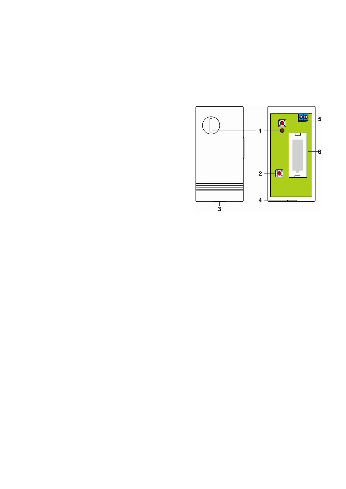
IIddeennttiiffyyiinngg tthhee PPaarrttss
11.. LLEEDD IInnddiiccaattoorr
22.. TTaammppeerr SSw
When the Door Contact is properly installed, the Tamper switch
will be compressed.
A Tamper close signal is transmitted when the Tamper is
compressed.
A Tamper open signal is transmitted when the Tamper is
released.
The Door Contact is learnt into the control panel when two sets
of Tamper close, Tamper open signals are transmitted
(pressing and release of the Tamper twice).
33.. BBaassee FFiitt HHoollee
Insert the Base Fit Hook into the Base Fit Hole to attach the
base-cover assembly
44.. BBaassee FFiitt HHooookk
55.. EExxtteennssiioonn TTeerrmmiinnaall
In addition to the built-in magnet switch, an additional 2-pin dry contact terminal
is provided for an extension magnet switch or any device with N.C. (Normally
Closed) functionality.
66.. BBaatttteerryy CCoommppaarrttmmeenntt
wiittcchh
AAcccceessssoorriieess IInncclluuddeedd
a) 1 Magnet
b) 2 Screws
c) 2 Wall Plugs
d) 1 Magnet double-sided adhesive tape pad
e) 2 Magnet mounting screws
f) 1 Mounting Bracket
LLEEDD IInnddiiccaattoorr
In Normal Operation Mode, the LED will not light when the Door Contact is activated with the exceptions listed below:
The LED will flash quickly for 2 seconds when Tamper Switch is pressed or released even in Normal Operation
Mode.
When the cover is opened or the tamper switch is released, the LED will flash quickly for 2 seconds.
When a tamper open condition persists, every time the Door Contact is activated, the LED will flash quickly for 2
seconds.
When the cover is closed or the tamper switch is compressed, the LED will flash quickly for 2 seconds.
When the Door Contact is in Low Battery Mode, every time it is activated (device opened/closed), the LED will flash
quickly for 2 seconds.
When the battery is depleted, the LED flashes once every 4 seconds and all Door Contact functions are stopped.
1
Page 2
BBaatttteerryy
The Door Contact uses one CR123A, 3V Lithium battery as its power source. Please note: ALWAYS replace battery
The Door Contact can detect if the battery is low. When the Battery is low, a low battery signal will be sent to the
When the battery is depleted, the LED flashes once every 4 seconds and the Door Contact will stop all function.
with the correct size and voltage.
Control Panel along with regular transmission. The LED will also flash quickly for 2 seconds when the Door Contact is
activated under low battery status.
Battery Change
I. Detach the base and cover assembly.
II. Remove the old battery.
III. Press the Tamper Switch a few times.
IV. Fit a new battery into the battery compartment. Please orient the battery according to the correct polarity.
V. Reattach the base and cover assembly.
TTaammppeerr SSwwiittcchh
Tamper Switch provides tamper protection against unauthorized device opening.
The Tamper switch is in normal operating position (Tamper closed) when the spring is compressed against the inside
of device cover. Tamper violation happens when the cover is removed from the base and releases the tamper switch.
SSuuppeerrvviissoorryy SSiiggnnaall
The Door Contact will automatically transmit Supervisory Signals period icall y to th e Control Pa nel at ran dom i ntervals
of 30-50 minutes.
The supervision time is reset whenever a signal is transmitted. (such as Tamper open signal, Tamper close signal,
etc.).
GGeettttiinngg SSttaarrtteedd
Detach the base and cover assembly.
Insert the “CR123A” battery into the battery holder connecting the polarity correctly.
Put the Control Panel into learning mode. Please refer to your Control Panel user
manual.
Press and release the Tamper Switch twice to send learn code to Control Panel.
Refer to your Control Panel operation manual’s to complete the learn-in process.
To check for range, please refer to the control panel user manual for what type of
signal transmission is needed from the Door Contact. (A Tamper open signal is
usually needed)
Proceed with mounting and installation once you are satisfied with the location of the
Door Contact.
MMoouunnttiinngg MMeetthhooddss aanndd IInnssttaallllaattiioonn
It is recommended that the Door Contact should be placed on the door frame and
the magnet on the door.
Step 1: Find a suitable location close to a door/window to install the Door Contact.
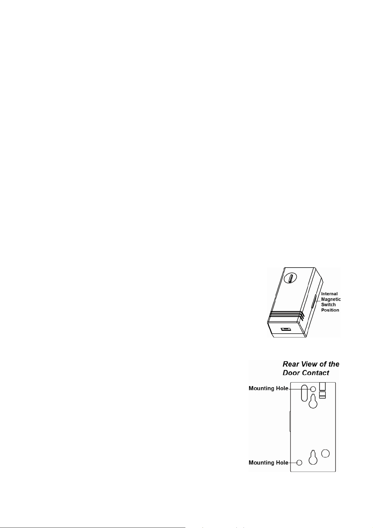
Step 2: Option A: Base mounting:
I. Detach the base and cover assembly
II. Using the mounting holes as templates, drill holes in the
surface
III. Insert the wall plugs if fixing into plaster or brick
IV. Screw the base into the wall plugs
V. Reattach the base and cover assembly
Option B: Using the Mounting Bracket:
I. Using the Bracket Mounting Holes as templates, drill holes in
the surface
II. Insert the wall plugs if fixing into plaster or brick
III. Screw the Mounting Bracket into the wall plugs
IV. Hook the Door Contact onto the Mounting Bracket
2
Page 3

Step 3: The Door Contact has an Internal Magnetic Switch Position marked by a protrusion
on one side (refer to figure) of the Door Contact. Ensure the Internal Magnetic Switch
side is facing the magnet.
Step 4: Fit the magnet on the door using the small piece of double sided adhesive tape or
with provided screws. The magnet must align with the marked side of the door
contact.
>
<<NNOOTTEE>
The magnet should not be more than 15 mm from the detector when the door is
closed.
Windows can be protected similar to door installations. When fitting to a window
fix the magnet to the moving window part and the door switch to the stationary
frame.
UUssiinngg tthhee EExxtteennssiioonn TTeerrmmiinnaall..
The Door Contact has an Extension Terminal providing enhanced installation flexibility.
The Extension terminal may be useful for the following:
If the Door Contact cannot be mounted on the door frame, you can connect an
additional extension magnet switch to the Extension Terminal and mount the
Door Contact remotely.
More than one window and door can be protected by a Door Contact usi ng the
additional magnet and extension magnet switch. The switches must be wired to
the Extension Terminal as shown:
Any dry contact device with N.C. (Normally Closed), such as a Broken Glass
detector, Smoke Sensor, Gas detector, Water Sensor etc, can be connected to
the Extension Terminal. Allowing the Door Contact to serve as an Universal
Transmitter.
The Extension Terminal forms a closed loop with the device connected t o it. When the
Loop is opened (the device is triggered), the Door Contact is activated.
The device connected to the Extension Terminal is in series with the internal magnet
Switch. Meaning both can work together simultaneously.
You can choose to use the Extension Terminal and bypass the internal magnet switch or
to use both together.
CCOONNNNEECCTTIINNGG TTHHEE EEXXTTEENNSSIIOONN TTEERRMMIINNAALL::
Step 1: Detach the base and cover assembly.
Step 2: The rear of the Door Contact has an Extension Hole designed specifically to allow
external wiring connections.
Step 3: Connect the external device(s) to the Extension Terminal as
shown in the diagram.
>
<<NNOOTTEE>
If both the Internal Magnet Switch and Extension
Terminal operate together, then:
When the protected door is opened/closed or
device is triggered, the Door Contact activates and transmits a
signal immediately .
However, the Door contact will only transmit a Door Closed
or Restored signal after both the door and
device are restored for 3 sec.
FCC Statement
This device complies with Part 15 of the FCC Rules. Operation is subject to the following two conditions:
(1) This device may not cause harmful interference, and
(2) This device must accept any interference received, including interference that may cause undesired operation.
FCC Caution:
To assure continued compliance, any changes or modifications not expressly approved by the party responsible for compliance may
void the user's authority to operate this equipment. (Example - use only shielded interface cables when connecting to computer or
peripheral devices).
the external
the external
3
 Loading...