

1
LM-1ZW Ambient Light Sensor
Introduction
LM-1ZW is a Z-Wave Ambient Light Sensor. It monitors your home environment and transmits measured Illuminance (lux),
to the coordinator in the Z-Wave network.
The Sensor is a Z-Wave enabled device and is fully compatible with any Z-Wave enabled network.
Z-Wave is a wireless communication protocol that uses a low-power RF radio. By taking advantage of the Z-Wave mesh
network, commands can be transmitted to their destination via intermediary “listening” Z-Wave products.
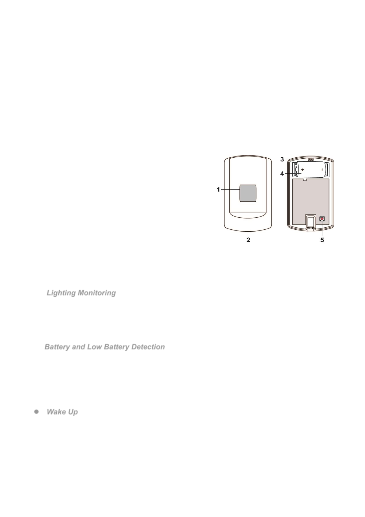
Parts Identification
1. Light Sensor / LED Indicator
- Flashes once: Transmitting Learning Code
- Light on 1 second: Factory Reset / successfully excluded from
Z-Wave Gateway/Control Panel.
- Flashes 3 times: After the sensor has successfully added into
Z-Wave Gateway/Control Panel.
2. Cover-Fixing Screw
3. Fixing Hook
4. Battery Compartment
5. Function Button
- Press once to send a signal to the coordinator.
- Press and hold for 10 seconds to factory reset.
- Press for 3 times within 1.5 seconds to transmit learning code.
Features
Lighting Monitoring
The sensor measures illuminance to transmit measured data to Z-Wave Control Panel/Gateway regularly.
Illuminance reading is transmitted every 1minute.
The sensor will also transmit signal automatically when:
The current illuminance changes by +/- 30%.
The current illuminance changes by +/-500 (lux)
The illuminance detection range is 0~180000(lux)
Battery and Low Battery Detection
The sensor uses one CR123A 3V Lithium battery as its power source.
The sensor features Low Battery Detection function. When the battery voltage is low, the sensor will transmit Low
Battery signal to the Gateway/Control Panel. The Sensor will report its battery percentage to the Gateway/Control
Panel respectively at 100% (voltage 3.2 to 2.85V), 75%(voltage 2.84 to 2.72V), 50%(voltage 2.71 to 2.59V) and
25% (voltage 2.58 to 2.33V). If the battery voltage is low (25%), a Low Battery signal will be sent to the Control
Panel to notify the user.
When changing battery, after removing the old batteries, press the Function Button twice to fully discharge before
inserting new battery.
Wake Up
This function uses the Z-Wave Wake Up Command Class. The Wake Up Command Class allows the battery-powered
Sensor to notify the Control Panel/Gateway that it is awake and ready to receive any queued commands. The wake up
time period is programmed automatically according to Control Panel’s setting when The Sensor is included. The
recommended setting of the wake up time is 60 minutes above.

2
Adding Device (Inclusion)
This product can be included and operated in any Z-Wave network with other Z-Wave certified devices from other
manufactures and/or other applications. All non-battery operated nodes within the network will act as repeaters
regardless of vendor to increase reliability of the network.
Put the Z-Wave gateway or control panel into Inclusion mode (please refer to the Z-Wave gateway or control
panel manual).
Within 1.5 seconds, press the Function Button 3 times.
Refer to the operation manual of the Z-Wave gateway or control panel to complete the adding process.
If the Sensor has already been added (included) into another Z-Wave Gateway/Control Panel, or if the device is
unable to be added into the current Z-Wave Gateway/Control Panel, try removing it first (see Removing
Device).
Removing Device (Exclusion)
The Sensor must be removed from existing Z-Wave network before being added into another.
Exclusion Mode
Put the Z-Wave gateway or control panel into Exclusion mode (please refer to the Z-Wave gateway or control
panel manual).
Within 1.5 seconds, press the Function Button 3 times and the Sensor will be removed from the Z-Wave
network, the LED will light on for 1 second to indicate.
Factory Reset
(Only use factory reset when network Control Panel/Gateway is missing or inoperable).
Remove the battery of the Sensor first.
Press and hold the Function Button. While holding the Function Button, power on the Sensor by re-inserting the
battery, wait for 10 seconds to factory reset, the LED will light on for 1 second to indicate.
<NOTE>
Factory resetting the Sensor will restore it to factory default settings (excluded from the Z-Wave network).
The Z-Wave gateway or control panel will still keep its Z-Wave settings. Please refer to the gateway or
control panel manual on how to remove the Sensor Z-Wave settings.
Range Test
To test whether the Sensor is able to communicate with the Z-Wave gateway or control panel:
Put the gateway / panel into range test mode (Walk Test).
Press the Function Button on the Sensor.
The gateway / panel should display if the device is within the operation range (please refer to the operation
manual of the gateway / panel).
Z-Wave Sleep Mode
The Sensor will enter Z-Wave Sleep mode (to conserve power) after waking up for a short period of time (~10
seconds). While in Z-Wave sleep mode, Z-Wave gateways or control panels are unable to send commands to
the Sensor.
To program the Sensor using the Z-Wave Gateway/Control Panel, please send command(s) to the Sensor
within the wake-up period.
Installation
Mounting the Sensor
The sensor can be mounted using two methods: Self-adhesive or Screw
mounting.
Self adhesive mounting
1. Clean the surface with a suitable degreaser.
2. Remove the protective covering from one side of double-sided adhesive
pad and firmly apply to the back of the device.
3. Remove the other covering and firmly place/press the device in the desired
location.
Do not use the Self-adhesive mounting method on poorly painted and/or
rough surfaces.
Screw Mounting
The base of the sensor has two screw knockouts, where the plastic is thinner
for mounting purposes. To mount the sensor:
1. Detach the Top Cover and Base assembly by loosening the Cover-Fixing Screw using a Philips screwdriver.

3
2. Break through the knockouts on the base.
3. Use the holes as a template to drill two holes and insert the wall plugs.
4. Screw the base into the wall plugs.
5. Replace the top cover over the base by hooking the base onto the fixing hook and pushing the cover towards the
base.
6. Secure and screw the top cover back on to its base using a Philips screwdriver.
Z-Wave Information
Device Type: Sensor Multilevel
Role Type: Reporting Sleeping Slave (RSS)
Maximum number of devices in group 1: 3
Maximum number of devices in group 2: 3
Command Class Support/Control
Mandatory CC Support: Association CC, v2 (security 2)
Association Group Information CC (security 2)
Supervision CC (security 2)
Battery CC (security 2)
Device Reset Locally CC (security 2)
Manufacturer Specific CC, v2 (security 2)
Sensor Multilevel CC, V5 (security 2)
Version CC, v2 (security 2)
Wake UP CC, v2 (security 2)
Z-Wave Plus Info CC, v2
Power Level CC (security 2)
Firmware Update MD CC,v4 (security 2)
Transport Service CC, v2
Z-Wave’s Groups (Association Command Class Version 2)
Group 1 for “LifeLine”:
Sensor Multilevel CC,V5 (COMMAND_CLASS_SENSOR_MULTILEVEL)
Battery CC (COMMAND_CLASS_BATTERY)
Device Reset Locally CC
Group 2 for “Luminance Report”:
Sensor Multilevel CC, V5 (COMMAND_CLASS_SENSOR_MULTILEVEL)
Group 2 will send “Luminance Report” according to the following conditions:
The current illuminance changes by +/- 30%.
The current illuminance changes by +/-500 (lux).
Every time when the Sensor wakes up.
 Loading...