

Page 1
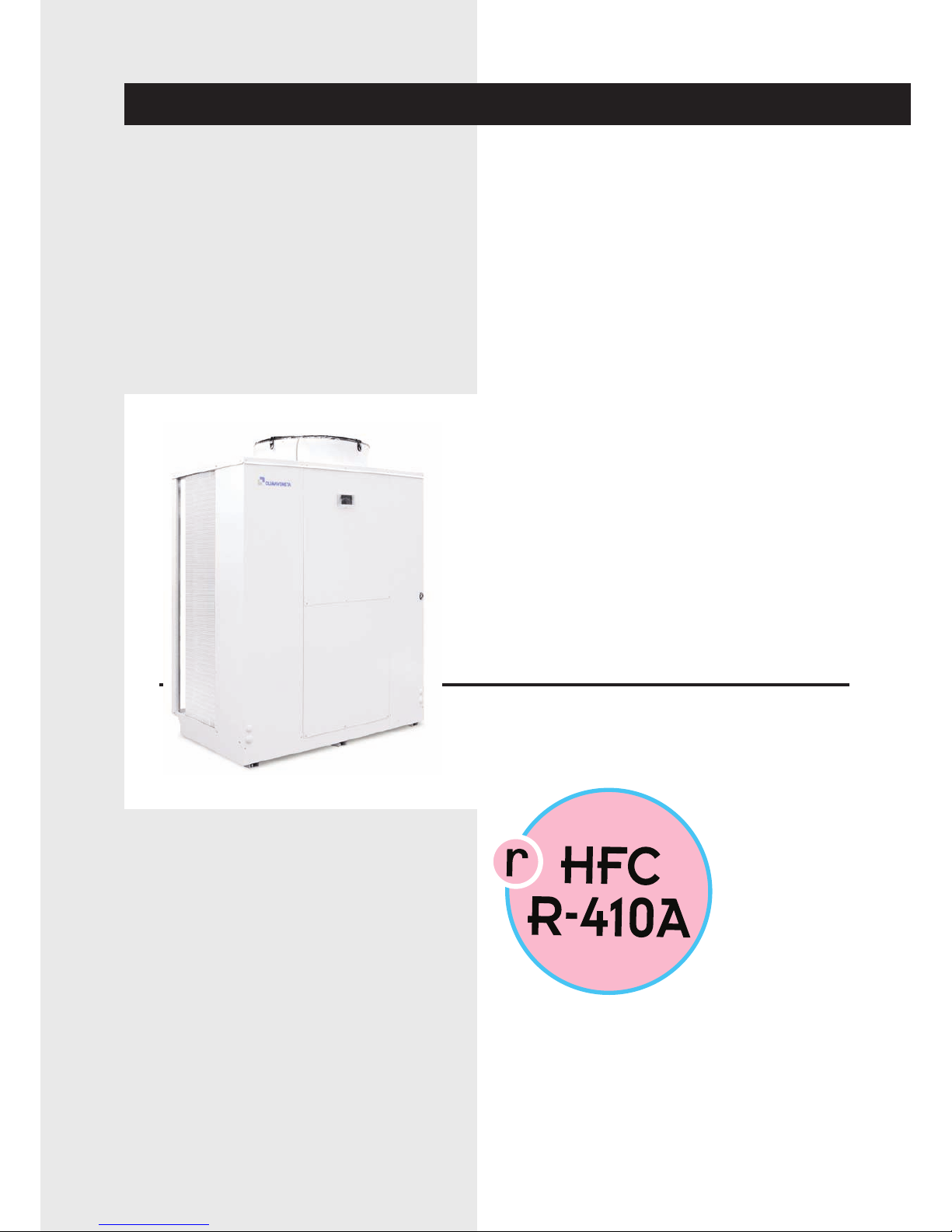
INSTALLATION-OPERATING-SERVICE MANUAL
MICS FF
MICS-N FF
0072÷0182
Air/water chillers and heat
pumps with axial-flow fans and
pump assembly.
Page 2

Page 3
General warnings 2
Fundamental safety rules 2
Identification 3
Receiving and handling the product 3
Description of standard unit 4
Dimensioned drawings 5
Installation 6
Hydraulic connections 6
Electrical connections 8
General technical data 12
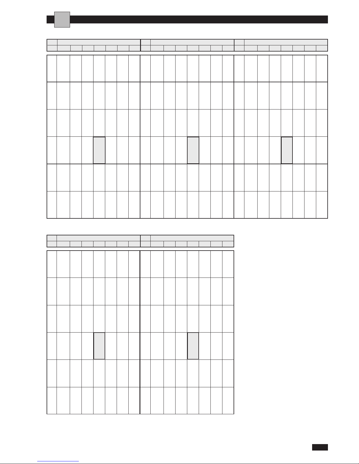
Cooling performance MICS 13
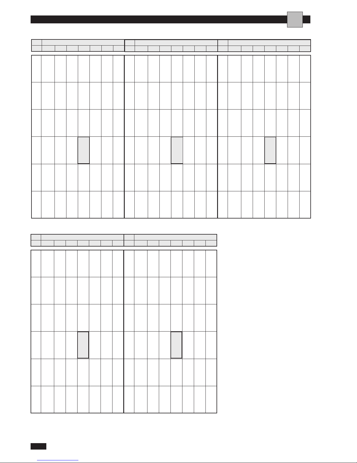
Cooling performance MICS-N 14
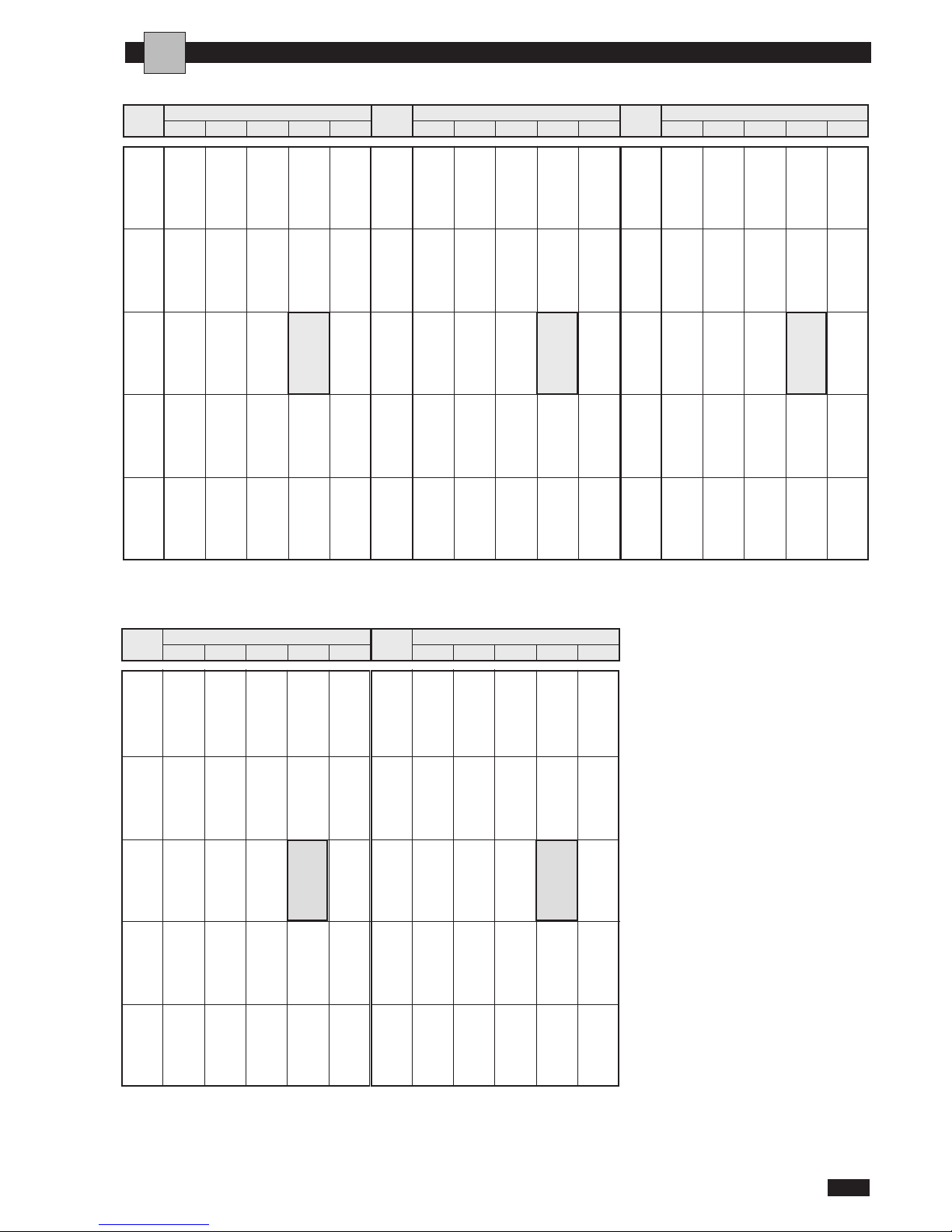
Heating performance MICS-N 15
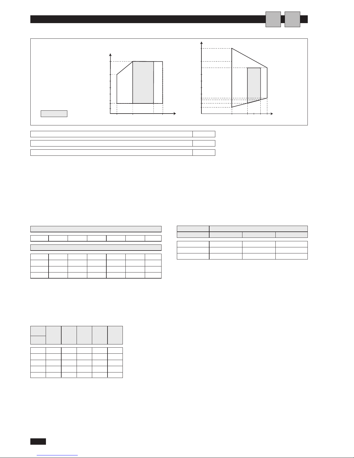
Operating limits 16
Hydraulic data 17
Checking and starting up the unit 18
Activating and deactivating the unit 20
Setting service parameters 20
Displaying alarms 21
Operating characteristics 22
Shutting down for long periods 23
Routine maintenance 23
Extraordinary maintenance 23
Troubleshooting 24
Useful information 26
U I A
U I A
U I A
I A
I A
I
I
I A
I A
I A
A
A
A
I A
I A
A
I A
A
A
I A
A
A
A
A
A
I
NDICE
MICS / MICS-N
1
English 07/07
70°C
A
I
U
The manufacturer reserves the right to modify the data in this manual without warning.
Eurovent certification program.
The following symbols are used in this publication and inside the unit:
U
I
I
IU
ENVIRONMENTAL INFORMATION:This equipment contains fluorinated greenhouse gases covered by the Kyoto Protocol.
It should only be serviced or dismantled by professional trained personnel. R410A GWP=1975
User
Installe
Assistance
Important
Prohibition
Danger voltage
Danger moving blades
Danger high temperatures
Page 4
G
ENERAL WARNINGS
MICS / MICS-N
2
English 07/07
These units have been designed to chill and/or
h
eat water and must be used in applications compatible with their performance characteristics.
Incorrect installation, regulation and maintenance or
improper use absolve the manufacturer from all
liability, whether contractual or otherwise, for damage to people, animals or things. Only those applications specifically indicated in this list are permitted.
Read this manual carefully. All work must be
carried out by qualified personnel in conformity
with legislation in force in the country concerned.
Th e guarant ee is i nv alid ated if th e above
instructions are not respected and if the unit is
started up for the first time without the presence
of personnel authorised by the Company (where
specified in the supply contract) who should draw
up a “start-up” report.
The documentation supplied with the unit
must be consigned to the owner who should keep
it carefully for future consultation in the event of
maintenance or service.
W
hen the items are consigned by the carrier,
check that the packaging and the unit are undamaged. If damage or missing components are noted,
indicate this on the delivery note. A formal complaint should be sent via fax or registered post to
the After Sales Department within eight days from
the date of receipt of the items.
When operating equipment involving the use of electricity
and water, a number of fundamental safety rules must be
observed, namely:
The unit must not be used by children or by
unfit persons without suitable supervision.
Do not touch the unit with bare feet or with
wet or damp parts of the body.
Do not carry out cleaning operations without
first disconnecting the system from the electricity
supply by placing the mains switch in the “off” position.
Do not modify safety or regulation devices without authorisation and instructions from the manufacturer.
Do not pull, detach or twist the electrical cables
coming from the unit,even when disconnected from
the mains electricity supply.
Do not open doors or panels providing access
to the internal parts of the unit without first ensuring that the mains switch is in the off position.
Do not introduce pointed objects through the
air intake and outlet grills.
Do not dispose of, abandon or leave within reach
of children packaging materials (cardboard, staples,
plastic bags, etc.) as they may represent a hazard.
Respect safety distances between the unit and
other equipment or structures. Guarantee adequate
space for access to the unit for maintenance and/or
service operations;
Power supply: the cross section of the electrical
cables must be adequate for the power of the unit
and the power supply voltage must correspond with
the value indicated on the respective units. All units
must be earthed in conformity with legislation in
force in the country concerned.
Hydraulic connections should be carried out as
indicated in the instructions to guarantee correct
operation of the unit. Empty the water circuit or add
glycol if the unit is not used during the winter.
Handle the unit with the utmost care (see weight
distribution table) to avoid damage.
FUNDAMENTAL SAFETY RULES
U
A
I
U
A
I
Page 5
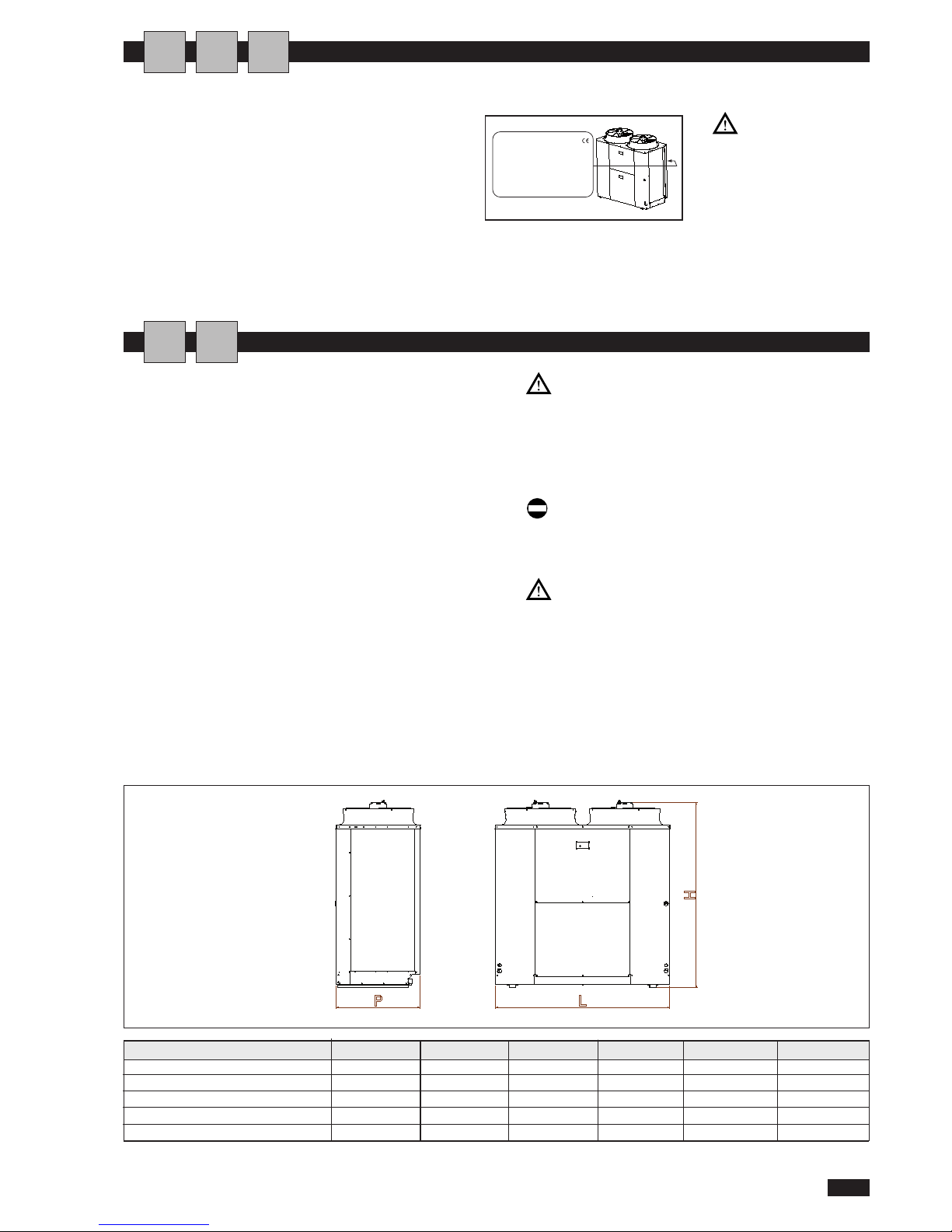
Dimensione 0072 0092 0122 0152 0182
H 1725 1725 1725 1725 1725 mm
L 1040 1040 1630 1630 1630 mm
P 790 790 790 790 790 mm
Gross weight MICS 340 360 440 480 510 kg
Gross weight MICS-N 360 380 470 510 540 kg
MICS / MICS-N
3
Italiano 05/07
The
MICS / MICS-N
chiller can be identified by the:
Rating plate
Giving the technical and performance data of the unit. If
this is lost, ask the After Sales Service for a replacement.
Tampering with or
t
he re moval or
absence of rating plates or
other means enabling the
unit to be identified causes
problems during installation and maintenance.
IDENTIFICATION
POTENZA FRIGORIFERA ------------------- kW
POTENZA TERMICA ------------------- kW
TIPO REFRIGERANTE ------------------CARICA REFRIGERANTE ------------------- Kg
PRESSIONE MASSIMA ------------------- bar
ALIMENTAZIONE ELETTRICA DI POTENZA ------------------- V---Hz
ALIMENTAZIONE ELETTRICA AUSILIARI ------------------- V---Hz
POTENZA ELETTRICA MAX. ASSORBITA ------------------- kW
CORRENTE MAX. ASSORBITA ------------------- A
CORRENTE DI SPUNTO ------------------- A
SCHEMA ELETTRICO ------------------- N°
P
ESO IN FUNZIONAMENTO ------------------- Kg
ANNO DI FABBRICAZIONE -------------------
RECEIVING AND HANDLINGTHE PRODUCT
The
MICS / MICS-N
chillers are supplied accompanied
by:
- installation, operating and service manual;
-guarantee certificate;
- CE declaration;
These are contained in a plastic bag attached to the top of
the chiller.
The unit should always be handled by qualified personnel
using equipment adequate for the weight of the chiller. If a
forklift truck is used, insert the forks under the base, spacing the forks as wide apart as possible. If a crane is used,
pass the cables through the bottom of the base, making
sure they do not exert pressure on the unit. Once the
packaging has been removed, the appliance can be lifted
and moved by inserting two metal tubes (max. diameter
1”) into the special holes in the base and using suitable
handling equipment.
The ins t a l lation, o peratin g a n d s e r v i ce
manual is an integral part of the unit and should
therefore be read and kept carefully.
It is recommended that the packaging should
not be removed until the unit is located in the
installation site.
Do not dispose of packaging materials in the environment or leave them within reach of children as
they may represent a hazard.
During transport, the chiller should be kept in a
vertical position
U
A
I
I
A
Page 6
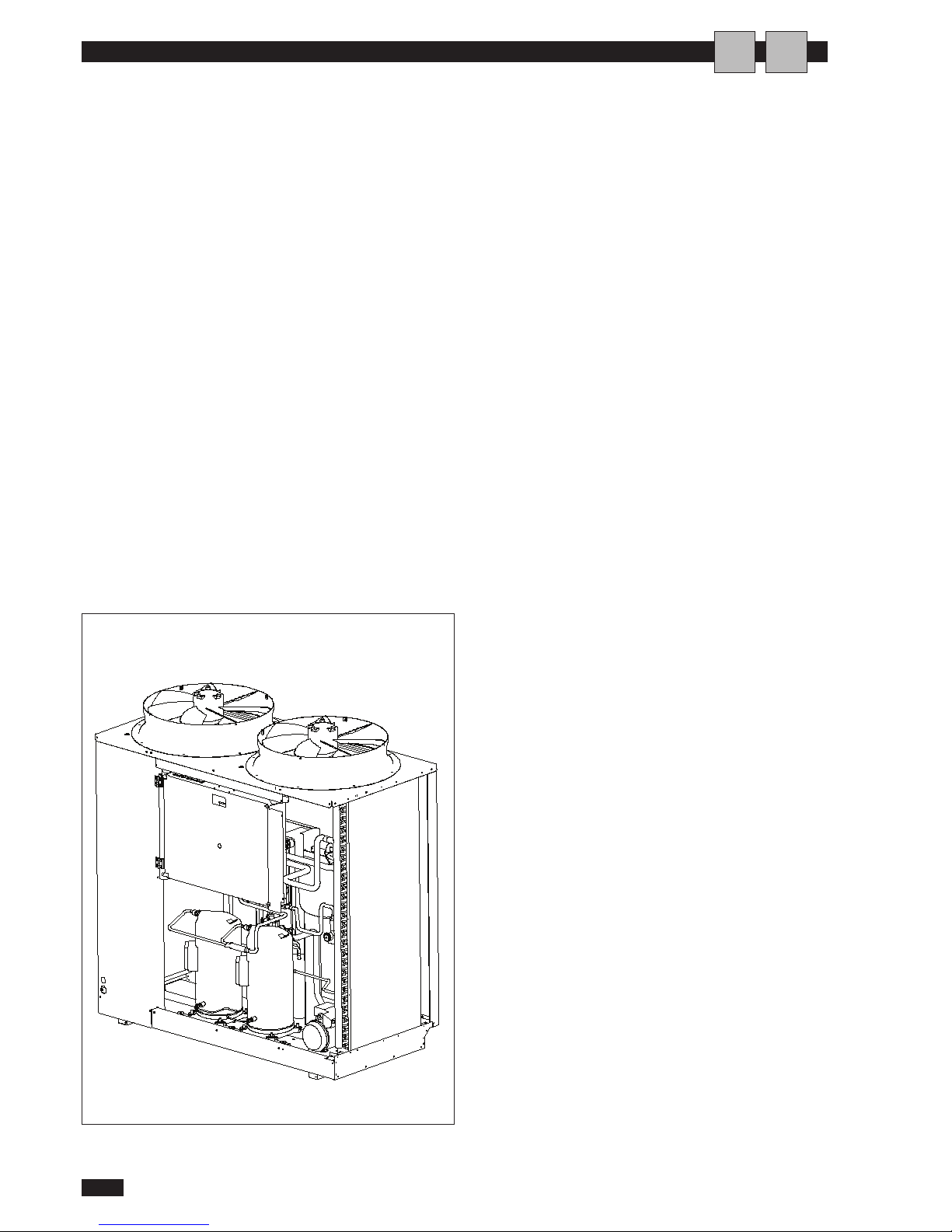
DESCRIPTION OF STANDARD UNIT
The air-cooled chillers with axial-flow fans operate with
refrigerant R410A and are suitable for installation outdoors.
T
he units satisfy the essential requirements of directives
98/37/EC, 73/23/EEC, 89/326/EEC, 97/23/EEC and subsequent amendments.
They are factory tested and on site installation is limited to
water and electrical connections.
STRUCTURE
Panels and base are made from galvanised steel plate painted
with epoxy powder to ensure total resistance to atmospheric agents.
COMPRESSORS
Hermetic rotary scroll compressor with thermal cut-out..
CONDENSING COILS
Made from copper tubes and aluminium fins with a large
exchange surface.
EVAPORATOR
AISI 316 stainless steel plate type evaporator complete with
differential pressure switch. Casing lined with anti-condensate closed cell neoprene cladding.
PUMPS
Multistage centrifugal pump with stainless steel hydraulic
a
ssembly and corrosion prevention device to prolong the
working life of the pump. Over-sized watertight bearings
with gasket ring resistant to thermal expansion eliminate the
problem of seizure.
PUMP ASSEMBLY
Pump assembly with expansion tank, safety valve, manual filling assembly, pressure gauge and pump.
FANS
External impeller axial-flow fans. Six-pole electric motor
with built-in thermal cut-out. Housed in aerodynamic tubes
with accident prevention grill. Device for operation with
low outside air temperatures: continuous fan rotation
speed control via pressure transducer.
REFRIGERANT CIRCUIT
Refrigerant circuit featuring the following components: filter,
liquid flow indicator, thermostatic expansion valve with
external equaliser. Pressure switches for controlling suction
and discharge pressure. Unit supplied complete with nonfreezing oil and R410A refrigerant charge, factory tested.
POWER AND CONTROL ELECTRICAL PANEL
Power and control electrical panel constructed in accordance
with IEC 204-1/EN60204-1, complete with compressor contactor and thermal solenoid switch and door lock safe-
ty device. Control via “HSW8” control panel.
OPTIONAL ACCESSORIES
- Removable metal mesh filter for water circuit
- Rubber vibration dampers.
- Remote keyboard kit.
- Coil protection grill kit.
The above accessories are optional. Consult the relative
documentation for assembly instructions and technical data.
MICS / MICS-N
4
English 07/07
AI
Page 7
600
600
600
600
W1
W
4
W2
W
3
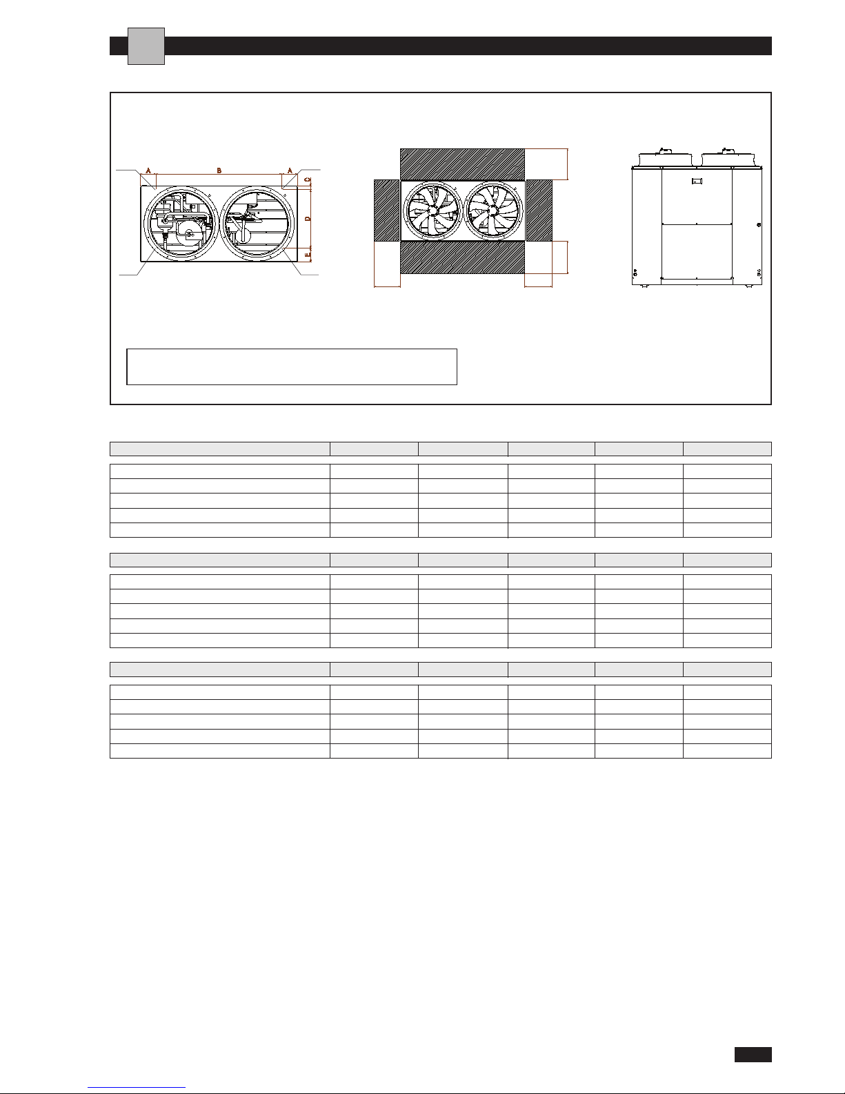
DIMENSIONED DRAWINGS
MICS / MICS-N
5
English 07/07
A 120 120 165 165 165
B 800 800 1300 1300 1300
C 44 44 44 44 44
D 602 602 602 602 602
E 144 144 144 144 144
Dimension 0072 0092 0122 0152 0182
W1 97 103 128 141 151
W2 89 95 118 129 137
W3 58 62 77 85 90
W4 66 70 87 95 102
Tot 310 330 410 450 480
W1 103 109 138 151 160
W2 95 101 126 137 146
W3 62 66 83 90 96
W4 70 74 93 102 108
Tot 330 350 440 480 510
I
1- Hydraulic connections IN 0072÷0182 Ø1”1/4
2- Hydraulic connections OUT 0072÷0182 Ø1”1/4
Weight distribution in operation MICS
0072 0092 0122 0152 0182
Weight distribution in operation MICS-N
0072 0092 0122 0152 0182
Page 8
INSTALLATION
MICS / MICS-N
HYDRAULIC CONNECTIONS
6
English 07/07
CHOICE OF INSTALLATION SITE
B
efore installing the unit, agree with the customer the site
where it will be installed, taking the following points into consideration:
- check that the fixing points are adequate to support the
weight of the unit;
- pay scrupulous respect to safety distances between the unit
and other equipment or structures to ensure that air entering
the unit and discharged by the fans is free to circulate.
- The unit must be installed in a space designed to house techni-
cal installations dimensioned according to legislation in force in
the country concerned and large enough to allow access for
maintenance.
POSITIONING
Before handling the unit, check the capacity of the lifting
equipment used, respecting the instructions on the packaging.
To move the unit in the horizontal, make appropriate use of a
lift truck or similar, bearing in mind the weight distribution of
t
he unit. To lift the unit, insert tubes long enough to allow
positioning of the lifting slings and safety pins in the special
holes in the base of the unit.
To avoid the slings damaging the unit, place protection
between the slings and the unit. Position the unit in the site
indicated by the customer. Place either a layer of rubber (min.
thickness 10 mm) or vibration damper feet (optional)
between the base and support surface. Fix the unit, making
sure it is level and that there is easy access to hydraulic and
electrical components. If the site is exposed to strong winds,
fix the unit adequately to the support surface using tie rods if
necessary.
The choice and installation of components is the responsibility of
the installer who should follow good working practice and current legislation. Before connecting the pipes, make sure they do
not contain stones, sand, rust, dross or other foreign bodies which might damage the unit. Construction of a bypass is recommended to enable the pipes to be washed through without having to
disconnect the unit (see drain valves). The connection piping
should be supported in such a way as to avoid it weighing on the
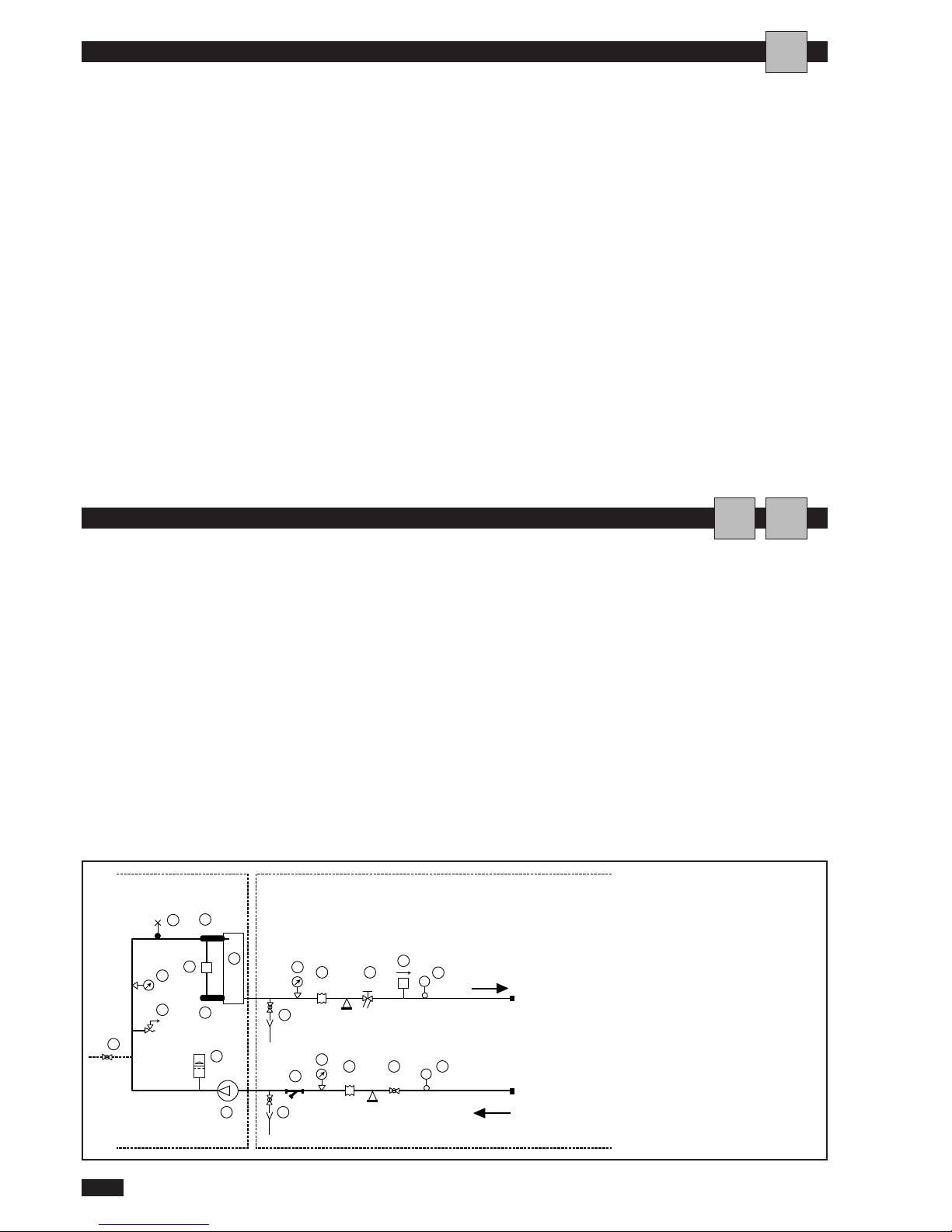
unit. It is recommended that the following devices are installed in
the water circuit of the evaporator:
1. Two pressure gauges with a suitable scale (inlet and outlet).
2. Two vibration damper joints (inlet and outlet).
3. Two gate valves (normal in inlet and calibrating in outlet).
4. A flow switch (inlet).
5. Two thermometers (inlet and outlet).
6. An inlet filter as close as possible to the evaporator and posi-
tioned to allow easy access for routine maintenance.
The flow of water to the refrigerating assembly must conform to
the values given on page 12.The flow of water must be maintained constant during operation. The water content of the unit
must be such as to avoid disturbing operation of the refrigerant
circuits. See the values given on page 17.
9
2 4
1
15
16
11
157
2 3
10
5
6
T
6
T
F
1
1
13
13
14
8
12
Collegamenti da eseguire
a cura dell'installatore
INGRESSO ACQUA IMPIANTO
USCITA ACQUA IMPIANTO
Collegamenti
eseguiti in fabbrica
1 Pressure gauge
2 Vibration damper joint
3 Gate valve
4 Calibrating valve
5 Flow switch
6 Thermometer
7 Pump
8 Safety valve
9 Air vent
10 Expansion tank
11 Mesh filter
12 Fill/top-up
13 Temperature sensor
14 Differential pressure switch
15 Drain/chemical washing valve
16 Plate heat exchanger
I
AI
HYDRAULIC CIRCUIT
Page 9
Installations containing antifreeze or covered by
s
pecific legislation must be fitted with hydraulic discon-
nectors.
The manufacturer is not liable for obstruction,
breakage or noise resulting from the failure to install
filters or vibration dampers.
Particular types of water used for filling or topp
ing up must be treated with appropriate treatment
systems. For reference values, see the table.
MICS / MICS-N
7
English 07/07
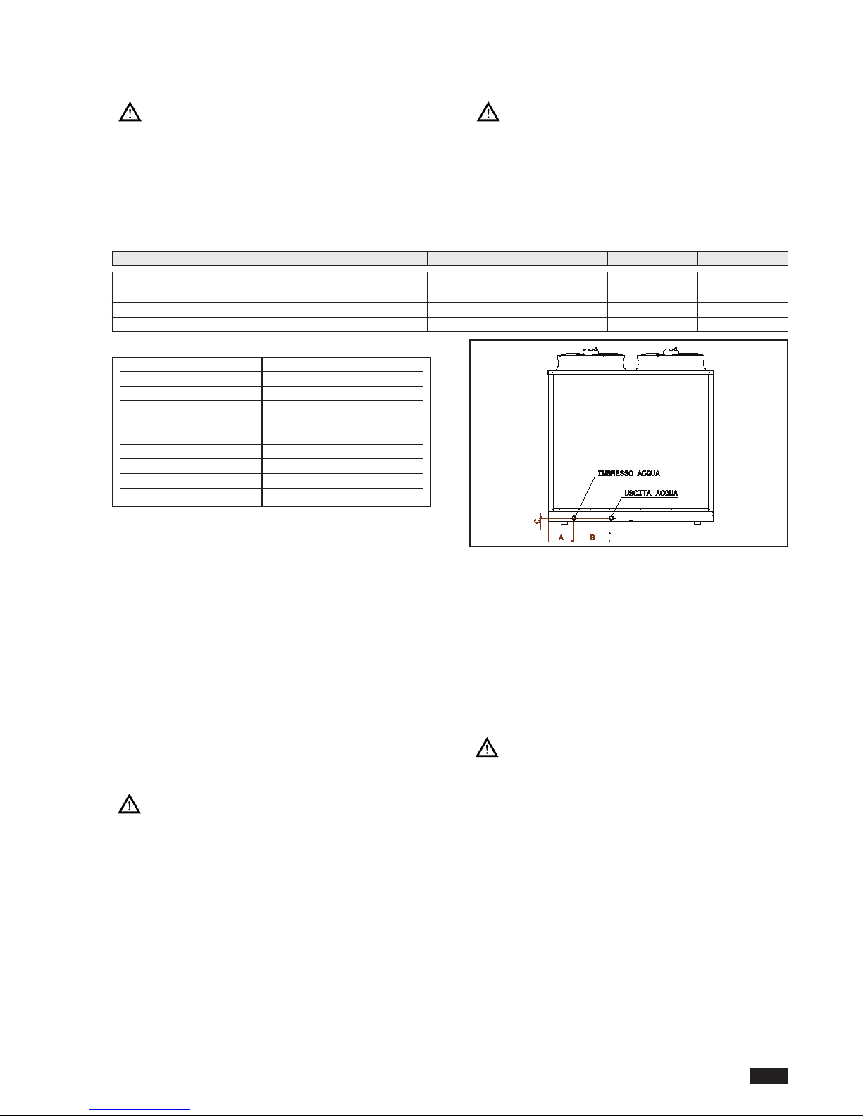
SIZE AND POSITION OF CONNECTIONS
FILLING THE INSTALLATION
- Remove the inspection panel.
- Before filling, check that the installation drain valve is
closed.
- Open all installation, appliance and terminal air vents.
- Open the gate valves.
- Begin filling, slowly opening the water filling cock inside
the unit.
- When water begins to leak out of the terminal air vent
valves, close them and continue filling until the pressure
gauge indicates a pressure of 1.5 bar.
- Replace the inspection panel
The installation must be filled to a pressure of
between 1 and 2 bar.
It is recommended that this operation be repeated after the unit has been operating for a number
of hours.The pressure of the installation should be
checked regularly and if it drops below 1 bar, the
water content should be topped-up.
Check the hydraulic tightness of joints.
EMPTYING THE INSTALLATION
- Remove the inspection panel.
- Before emptying, place the mains switch in the “off” position.
-
Make sure the installation fill/top-up water cock is
closed.
- Open all the installation air vent valves, the drain cock and
the terminals.
- Replace the inspection panel
If the fluid in the circuit contains antifreeze, it
should not be allowed to drain freely as it is pollutant. It
should be collected for possible reuse. When draining
after heat pump operation,take care as the water may be
hot (up to 50°).
PH 6-8
Electrical conductivity
less than
200 mV/cm (25°C)
Chlorine ions
less than
50 ppm
Sulphuric acid ions
less than
50 ppm
Total iron
less than
0,3 ppm
Alkalinity M
less than
50 ppm
Total hardness
less than
50 ppm
Sulphur ions none
Ammonia ions none
Silicon ions
less than
30 ppm
A (mm)
100 100 260 260 260
B (mm)
226,5 226,5 363 363 363
C (mm)
63 63 63 63 63
Hydraulic connections (Ø)
G1-1/4 G1-1/4 G1-1/4 G1-1/4 G1-1/4
Dimensione 0072 0092 0122 0152 0182
Page 10
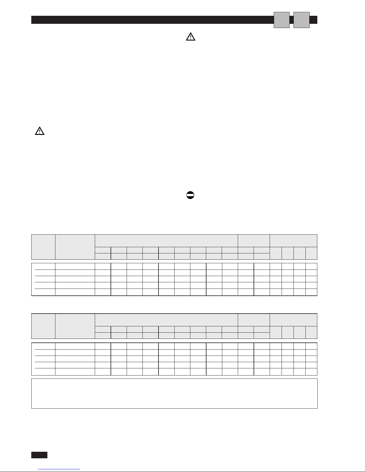
elettrica F.L.I. F.L.A. L.R.A. F.L.I. F.L.A. F.L.I. F.L.A. F.L.I. F.L.A. F.L.I. F.L.A.
FU1 FU4 FU5 FU6
(V-Ph-Hz) (kW) (A) (A) (kW) (A) (kW) (A) (kW) (A) (kW) (A)
0072
400-3 N ~ 50
5,9 11,2 48 0,6 2,8 0,7 4,8 7,2 18,8 9,9 23,6 1A 1A 0,5A 3,15
0092
400-3 N ~ 50
8,7 16,3 64 0,6 2,8 0,7 4,8 10,0 23,9 12 27,6 1A 1A 0,5A 3,15
0122
400-3 N ~ 50
9,5 16,6 74 1,2 5,6 0,7 4,8 11,4 27 19 40,4 1A 1A 0,5A 3,15
0152
400-3 N ~ 50
12,2 22,6 95 1,2 5,6 1,3 9,0 14,7 37,2 19,8 46,6 1A 1A 0,5A 3,15
0182
400-3 N ~ 50
14,3 25,9 111 1,2 5,6 0,9 5,4 16,4 36,9 25,1 53,0 1A 1A 0,5A 3,15
ELECTRICAL CONNECTIONS
MICS / MICS-N
8
English 07/07
The
M
ICS / MICS-N
chillers leave the factory already
wired, and ready for connection to the mains electricity supp
ly and for the flow switch and remote ON/OFF switch to be
connected.All the above operations must be carried out by
qualified personnel in compliance with the legislation in force.
For all electrical work, refer to the electrical wiring diagrams
in this manual.You are also recommended to check:
- That the characteristics of the mains electricity supply
are adequate for the power input values indicated in the
electrical characteristics table below, also bearing in mind
the possible use of other equipment at the same time.
Power to the unit must be turned on only after
installation work (mechanical, hydraulic and electrical) has been completed.
All electrical connections must be carried out
by qualified personnel in accordance with legislation
in force in the country concerned.
Respect instructions for connecting phase, neutral and earth conductors. The power line should be
fitted upstream with a suitable device to protect
against short-circuits and leakage to earth, isolating
the installation from other equipment.
Voltage must be within a tolerance of ±10% of the rated power supply voltage for the unit (for three phase
u
nits, the unbalance between the phases must not
exceed 3%). If these parameters are not respected,contact the electricity supply company.
For electrical connections, use double insulation
cable in conformity with current legislation in the
country concerned. Install, if possible near the unit, an
appropriate protection device to isolate the unit from
the mains supply.This should have a delayed characteristic curve, contacts opening by at least 3 mm and an
adequate interruption and residual current protection
capacity.
If these devices are not visible from the unit,
they should be lockable.
An efficient earth connection is obligatory. Failure to earth the appliance absolves the manufacturer of all liability for damage.
In the case of three phase units, ensure the
phases are connected correctly.
Do not use water pipes to earth the unit.
Rated values (1) FUSES
Model Electrical Compressor Fans Pump Total Max. values (3) Glass 5x20mm 250V
F.L.I. power input
F.L.A. current input
L.R.A. compressor start-up current
(1) Outside air temperature 35°C - Water temperature at evaporator 12/7°C.
(2) Outside air temperature 7°C - Water temperature at condenser 40/45°C.
(3) These values should be used to dimension protection switches and power
cables.
MICS ELECTRICAL DATA
AI
elettrica F.L.I. F.L.A. L.R.A. F.L.I. F.L.A. F.L.I. F.L.A. F.L.I. F.L.A. F.L.I. F.L.A.
FU1 FU2 FU3 FU4
(V-Ph-Hz) (kW) (A) (A) (kW) (A) (kW) (A) (kW) (A) (kW) (A)
Rated values (2) FUSES
Model Electrical Compressor Fans Pump Total Max. values (3) Glass 5x20mm 250V
MICS-N ELECTRICAL DATA
0072
400-3 N ~ 50
5,9 11,2 48 0,6 2,8 0,7 4,8 7,2 18,8 9,9 23,6 1A 1A 0,5A 3,15
0092
400-3 N ~ 50
8,0 14,9 64 0,6 2,8 0,7 4,8 9,3 22,5 12 27,6 1A 1A 0,5A 3,15
0122
400-3 N ~ 50
10,0 17,5 74 1,2 5,6 1,1 7,6 12,3 30,7 19,4 43,2 1A 1A 0,5A 3,15
0152
400-3 N ~ 50
12,8 23,7 95 1,2 5,6 0,9 5,4 14,9 34,7 19,4 43,0 1A 1A 0,5A 3,15
0182
400-3 N ~ 50
14,2 25,7 111 1,2 5,6 0,9 5,4 16,3 36,7 25,1 53,0 1A 1A 0,5A 3,15
Page 11
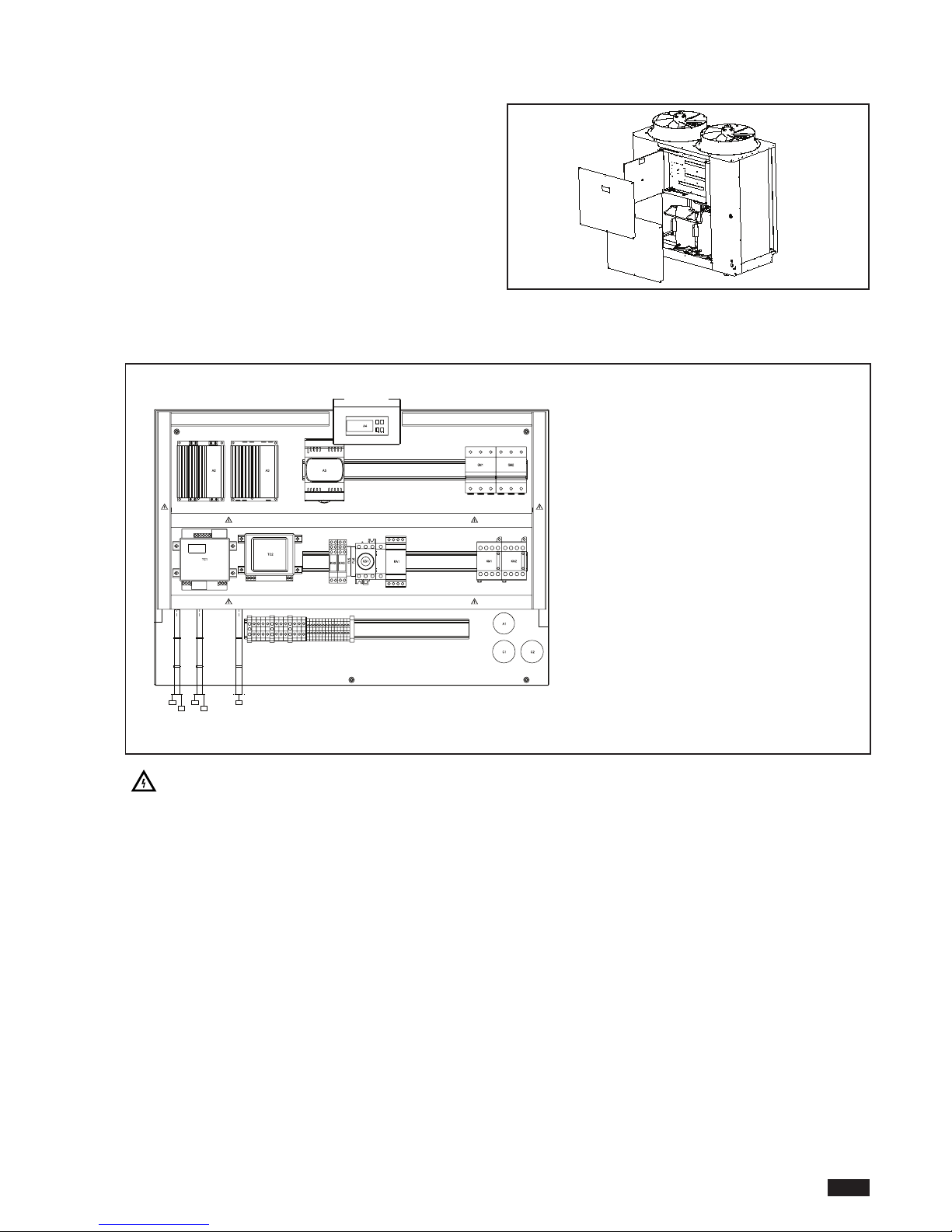
MICS / MICS-N
9
English 07/07
ACCESSINGTHE ELECTRICAL PANEL
T
he electrical panel is located inside the unit at the top of
the technical compartment where the various components
of the refrigerant circuit are also to be found.To access the
electrical panel, remove the front panel of the unit by
undoing the metric screws. To access the components in
the electrical panel and the terminal boards, undo the
screws and remove the part of the panel.
ELECTRICAL PANEL LAYOUT
Conduits containing live wires, even when the door lock disconnecting switch is off
A1 Radio interference suppresser
A2 Fan electronic control board
A3 Pump electronic control board
A4 Electronic controller
A5 EEV driver
C1-2 Fan start capacitor
C4 Interference suppresser capacitor
FU1 Transformer protection fuse
FU2 Auxiliar y circuit protection fuse
FU3 Fan protection fuse
FU4 Water pump protection fuse
FU5 TC2 transformer protection fuse
FU6 PCBs supply protection fuse
KA1 High pressure switch relay
KA2 Phase control relay
KA3 Alarm relay
KM1-2 Compressor contactor
QM1-2Compressor 1 circuit breake
QS1 Door lock disconnector switch
TC1 Safety transformer
TC2 Transformer
Page 12

MICS / MICS-N
10
English 07/07
ELECTRICAL POWER CONNECTIONS
F
or the functional connection of the unit, bring the power
supply cable to the electrical panel inside the unit and connect it to terminals U-V-W N and , res pect ing (U- VW) phases, (N) neutral and ( ) earth.
AUXILIARY CONNECTIONS
All terminals referred to in the explanations below are to
be found on the terminal board inside the electrical panel
and described as “installer terminals”.
REMOTE START UP AND SHUT DOWN
To be able to use a remote switching on and off device, a
switch must be connected to terminals 13 and 14 of the
installer terminal block. For timed operation, connect a daily or weekly timer between terminals 13 and 14 (see wiring
diagram)
.Select the parameter H07 from the control panel
HSW8 and put it to the value 1.
REMOTE HEATING/COOLING CONTROL
To fit a remote heating/cooling selector, the jumper must
be replaced with a switch connected to terminals 11 and
12 on the installer terminal board. To activate the command, proceed as follows:
- Select the parameter H06 on the HSW8 control panel
and set it to 1.
REMOTEALARM
For remote display of unit shut-down due to malfunction,
an audible or visual alarm warning device can be connected
between terminals 19 and 20. Connect the phase to terminal 20 and the alarm signal device between terminal 19 and
the neutral.
REMOTE KEYBOARD KIT
T
he remote keyboard kit can be used to display all unit
functions and access the parameters of the electronic
board from a point located at some distance from the unit
itself.
To install the kit, follow the instructions accompanying the
kit.
To avoid interference due to magnetic fields,the
use of shielded cable is recommended. The cable
should not be more than 100m long.
CONNECTING A FLOW SWITCH
If a flow switch is to be used, connect it to terminals 9 and
10 on the installer terminal board, after removing the
jumper.
COMPRESSOR ON SIGNAL
If the operation of the compressor needs to be signalled in
a remote position, terminals 17 and 18 can be connected
to an audible or visual signal device. Connect the phase to
terminal 18 and the signal device between terminal 17 and
the neutral.
Page 13
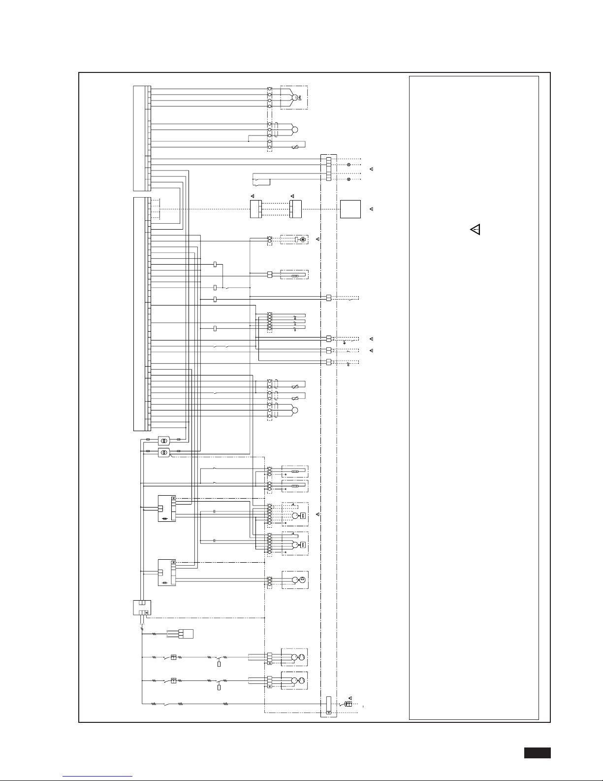
WIRING DIAGRAM
MICS / MICS-N
11
English 07/07
G G0
SUPPLY
A4
ANALOGINPUT
1oN5DI1DIDNGY
TUPNILATIGIDCF
C1/2 No2GNDGND
+to
+to
KM1
U-V-W-NPE
400V-3N 50Hz
QF1
U-V-W-N
L1-L2-L3-N
1
QS1
B1 B2
BP1 F2
3
M
KM1
Z1
QM1
T1
BT1 BT2
2 31
24VAC
R1
FU4
FU5
D
123
E
1 2 4567
1413
SA2
F
1 2
5 6
109
F4
F3
1211
SA1
C1/2 No3 C3/4 +10V GND No4 C3/4
R3
87
KM2
YV1
A
5 6
T2
T3
L1
L2
L3
N
U
DIGITALOUTPUT
B4 V+
PRESS.PROBE
0
1
20
0
23
21
25
26
28
31
30
14
8
32
34
38
3
5
41
1
8
43
44
5
45
15
25
26
30
33
33
35
19
15
25
26
25
26
28
31
3
0
14
8
32
2
8
31
30
32
2
8
31
32
34
38
3
5
41
34
1
1
38
3
5
15
34
1
1
38
43
44
45
43
45
43
45
3
M
KM2
Z2
QM2
T1
5 64
T2
T3
L1
L2
L3
654
24
KM2
R2
N4
L2
A1
U1
U3
1
M
E1
0
GND
27272727
3
9
3939393
ID4
43
F1
G G0
23
21
A5
GNDS3
52
5
3
BP2
S1
54
+to
BT3
2341
56
57
58
59
M
YV2
1
2
3
4
1
G
8765432
52
5
3
53
54
56
57
58
59
9
Vr1
5555
P
KA2
ID3
36
3
5
L2L1
KA1
L3
L2
L1
L3
KA2
1
42
42
4
GNDTxRx
NALNAL
GNX RT+
SUPPLY
4
6
47
46
4
7
KA1
ID2
INSTALLER TERMINAL BLOCK
MORSETTI PER INSTALLATORE
18
1
8
18
24
19
0
0
15
30
35
3
5
35
17 18
GN1
7
230VAC1A MAX
19 20
RD1
48
49
KM2KM1
48
COM NO
RELAY
51
5
0
1
5
15
w
hite
P
black
green
green
white
black
LOAD
+
A3
L
N
FU3
-
2345
C2
0
1
6
77
8
9
3131
7
6
M
1
EV2
U
1
U2
Z2
EEVANALOGINPUT
B3
KA3
1615
KA3
40
929230
SA3
15
40
TC1
24VAC
230VAC
0
FU1
C
1
6
6 7
T
W
TW
LOAD
+
A2
L
N
FU2
-
A
321
3
22
3
2
3
4
5
TW
TW
761
B
Z2
U2
U
1
EV1
1
M
5432
C1
KA2
37
3
6
TC2
6
6
7
6
9
Z1
Z1
2
3
6
7
0101
77
7
7
12
12
14
21
22
1
1
8
18
5
0
51
5252
5454
5353
5
555
5
656
5757
5858
5959
43
2
FU6
5
23
21
25
26
28
31
3
0
27
29
34
38
3
5
41
1
8
43
44
5
45
3
9
36
4
4
6
18
1
8
18
23
21
52
5
3
54
56
57
58
59
55
46
5
0
51
1414
----
KEY/ RS485
A6
A7
A8
6
6
6
GND TxRx+ TxRx-
GND TxRx+ TxRx-
1
KM1
0000
11
Factory installed components
A1 Noise suppression filter
A2 Plant water pump control board
A3 Condensation fan control board
A4 Electronic control
A5 EEV driver
A6 RS485 serial interface
A7 Supply module
A8 Remote terminal
BP1 Ratiometric cond./evap. pressure probe.
BP2 Low pressure side ratiometric pressure probe
BT1 Inlet water plant temperature sensor
BT2 Outlet water plant temperature sensor
BT3 Compressor suction temperature sensor
C1-2 Fan starting capacitor
E1 Plant water pump
EV1-2 Condensing air fan
F1 High pressure switch
F2 Low pressure switch
F3 Water differential pressure switch
F4 Flow switch
FU1 TC1 transformer protection fuse
FU2 Auxiliary circuit protection fuse
FU3 Fan protection fuse
FU4 Plant water pump protection fuse
FU5 TC2 transformer protection fuse
FU6 PCBs supply protection fuse
GN1 Green light (compressor ON)
KA1 Phase sequence control relay
KA2 High pressure switch relay
KA3 Load limitation relay
KM1 Compressor 1 contactor
KM2 Compressor 2 contactor
QF1 IRefrigerator group circuit breaker
QM1 Compressor 1 circuit breaker
QM2 ICompressor 2 circuit breaker
QS1 Door locking circuit breaker
R1 Compressor 1 crankcase heater
R2 Compressor 2 crankcase heater
R3 Frost heater
RD1 Red warning light (shut-off comp. signal)
SA1 Heating/cooling switch
SA2 Timer and/or on-off switch
SA3 Load limitation switch
TC1 Insulation transformer
TC2 230/24VAC transformer
YV1 Cycle reversing valve
YV2 Electronic expansion valvea
Z1 Compressor 1
Z2 Compressor 2
1 Switch (optional)
2 0122-0182 models only
3 Heating-cooling switch (optional), for models only coo-
ling clamps 8-9 closed
4 Timer and on-off switch (optional)
5 Heat pump only
6 Optional
7 Pilot lamps (optional)
Page 14
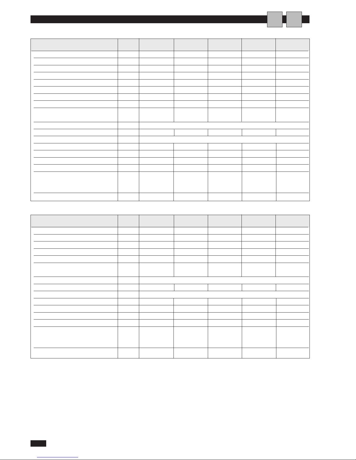
MICS / MICS-N
12
Italiano 05/07
GENERAL TECHNICAL DATA
I
A
MICS 0072 0092 0122 0152 0182
Cooling capacity (1) kW 18,2 23,0 31,9 39,4 44,7
Compressor power input (1) kW 5,9 8,7 9,5 12,2 14,3
Compressors n° 22222
Rated water flow m3/h 3,1 4,0 5,5 6,8 7,7
Residual head (1) kPa 130 140 105 125 120
Maximum allowable pressure
PS
L
Mpa
2,80 2,80 2,80 2,80 2,80
H 3,93 3,93 3,93 3,93 3,93
Electrical power supply V/ph/Hz 400-3 N ~ 50
Total power input (1) kW 6,5 9,3 10,7 13,4 15,5
Electrical index of protection IP X4
Fans n° 11222
Max.air flow m3/s 2,5 2,5 5,0 4,9 4,9
Noise level (3) dB(A) 68 68 71 71 71
R410A refrigerant charge kg 5,35 4,80 7,25 11,10 11,20
Copeland 3MAF (32 cSt)
Olio Mobil EAL Artic 22 cc lt 1,3 + 1,3 2,0 + 2,0 2,0 + 2,0 2,5 + 2,5 3,3 + 3,3
ICI Emkarate RL 32 CF
Operating weight kg 310 330 410 450 480
(1) condenser air in 35°C,evaporator water in/out 12/7°C
(2) evaporator air in 7°C ,condenser water in/out 40/45°C
(3) at 1m in open field fan side
*
compressor + fan
MICS-N 0072 0092 0122 0152 0182
Cooling capacity (1) kW 17,3 21,8 30,3 37,4 42,5
Compressor power input (1) kW 5,9 8,7 9,5 12,2 14,8
Potenza termica (2) kW 20,2 26,1 33,9 42,6 47,9
Compressor power input (2) kW 5,9 8,0 10,0 12,8 14,2
Compressors n° 22222
R
ated water flow (1) m3/
h 3,0 3,8 5,2 6,4 7,3
Rated water flow (2) m3/h 3,5 4,5 5,9 7,4 8,3
Residual head kPa 90 100 100 105 90
M
aximum allowable pressure
PS
L
Mpa
2,80 2,80 2,80 2,80 2,80
H 3,93 3,93 3,93 3,93 3,93
Electrical power supply V/ph/Hz 400-3 N ~ 50
Total power input (2) kW 6,5 8,6 11,2 14,0 15,4
Electrical index of protection IP X4
Fans n° 11222
Max.air flow m3/s 2,5 2,5 5,0 4,9 4,9
Noise level (3) dB(A) 68 68 71 71 71
R410A refrigerant charge kg 6,6 6,9 11,0 13,3 14,5
Copeland 3MAF (32 cSt)
Olio Mobil EAL Artic 22 cc lt 1,3 + 1,3 2,0 + 2,0 2,0 + 2,0 2,5 + 2,5 3,3 + 3,3
ICI Emkarate RL 32 CF
Operating weight kg 310 330 410 450 480
Page 15
MICS / MICS-N
13
English 07/07
COOLING PERFORMANCE MICS
A
Model 0152
Ta. Tw 5678910
Model 0182
Ta. Tw 5678910
Ta: outside air temperature (°C)
Pa: compressor power input (kW)
∆Pev: evaporator pressure drop (kPa)
Tw: evaporator water outlet temperature (°C)
Pat: total power input (kW)
Pf: cooling capacity (kW)
Qev: evaporator water flow (m
3
/h)
Pf 47,3 48,7 50,1 51,5 52,9 54,3
Pa 11,3 11,4 11,5 11,7 11,8 11,9
25,0 Pat 12,5 12,6 12,7 12,9 13,0 13,1
Qev 8,1 8,4 8,6 8,9 9,1 9,4
∆
Pev
53 57 60 64 67 72
Pf 44,7 46,1 47,5 48,8 50,2 51,5
Pa 12,6 12,7 12,9 13,0 13,1 13,2
30,0 Pat 13,8 13,9 14,1 14,2 14,3 14,4
Qev 7,7 7,9 8,2 8,4 8,6 8,9
∆
Pev
48 51 54 57 60 64
Pf 43,7 45,0 46,4 47,7 49,0 50,4
Pa 13,1 13,3 13,4 13,5 13,7 13,8
32,0 Pat 14,3 14,5 14,6 14,7 14,9 15,0
Qev 7,5 7,8 8,0 8,2 8,4 8,7
∆
Pev
46 49 52 54 57 61
Pf 42,1 43,4 44,7 46,0 47,3 48,7
Pa 14,0 14,1 14,3 14,4 14,6 14,7
35,0 Pat 15,2 15,3 15,5 15,6 15,8 15,9
Qev 7,2 7,5 7,7 7,9 8,2 8,4
∆
Pev
42 46 48 51 54 57
Pf 39,3 40,6 41,9 43,2 44,5 45,8
Pa 15,5 15,7 15,8 15,9 16,1 16,2
40,0 Pat 16,7 16,9 17,0 17,1 17,3 17,4
Qev 6,8 7,0 7,2 7,4 7,7 7,9
∆
Pev
37 40 42 44 48 51
Pf 37,5 38,8 40,1 41,4 42,8 44,1
Pa 16,5 16,6 16,8 16,9 17,1 17,2
43,0 Pat 17,7 17,8 18,0 18,1 18,3 18,4
Qev 6,5 6,7 6,9 7,1 7,4 7,6
∆
Pev
34 36 39 41 44 47
Pf 41,6 42,9 44,2 45,5 46,8 48,1
Pa 9,5 9,6 9,7 9,8 9,9 10,0
25,0 Pat 10,7 10,8 10,9 11,0 11,1 11,2
Qev 7,2 7,4 7,6 7,8 8,1 8,3
∆
Pev
54 57 60 63 68 72
Pf 39,4 40,7 41,9 43,2 44,5 45,7
Pa 10,7 10,8 10,9 11,0 11,1 11,2
30,0 Pat 11,9 12,0 12,1 12,2 12,3 12,4
Qev 6,8 7,0 7,2 7,4 7,7 7,9
∆
Pev
48 51 54 57 62 65
Pf 38,4 39,7 40,9 42,2 43,4 44,7
Pa 11,2 11,3 11,4 11,5 11,6 11,7
32,0 Pat 12,4 12,5 12,6 12,7 12,8 12,9
Qev 6,6 6,8 7,0 7,3 7,5 7,7
∆
Pev
45 48 51 55 58 62
Pf 37,0 38,2 39,4 40,6 41,8 43,0
Pa 12,0 12,1 12,2 12,3 12,4 12,5
35,0 Pat 13,2 13,3 13,4 13,5 13,6 13,7
Qev 6,4 6,6 6,8 7,0 7,2 7,4
∆
Pev
43 45 48 51 54 57
Pf 34,3 35,5 36,6 37,7 38,8 39,9
Pa 13,5 13,6 13,7 13,8 13,9 14,0
40,0 Pat 14,7 14,8 14,9 15,0 15,1 15,2
Qev 5,9 6,1 6,3 6,5 6,7 6,9
∆
Pev
36 39 41 44 47 49
Pf 32,6 33,7 34,8 35,8 36,9 37,9
Pa 14,5 14,6 14,7 14,8 14,9 14,9
43,0 Pat 15,7 15,8 15,9 16,0 16,1 16,1
Qev 5,6 5,8 6,0 6,2 6,4 6,5
∆
Pev
33 35 37 40 43 44
Pf 19,3 19,9 20,5 21,2 21,8 22,4
Pa 4,6 4,6 4,6 4,7 4,7 4,7
25,0 Pat 5,2 5,2 5,2 5,3 5,3 5,3
Qev 3,3 3,4 3,5 3,6 3,8 3,9
∆
Pev
39 41 43 46 51 54
Pf 18,2 18,8 19,4 20,0 20,6 21,2
Pa 5,1 5,2 5,2 5,3 5,3 5,3
30,0 Pat 5,7 5,8 5,8 5,9 5,9 5,9
Qev 3,1 3,2 3,3 3,4 3,5 3,6
∆
Pev
34 36 39 41 43 46
Pf 17,8 18,3 18,9 19,5 20,1 20,7
Pa 5,4 5,4 5,5 5,5 5,6 5,6
3
2,0 Pat 6,0 6,0 6,1 6,1 6,2 6,2
Qev 3,1 3,2 3,3 3,4 3,5 3,6
∆
Pev
34 36 39 41 43 46
Pf 17,1 17,6 18,2 18,8 19,3 19,9
Pa 5,8 5,8 5,9 5,9 5,9 6,0
35,0 Pat 6,4 6,4 6,5 6,5 6,5 6,6
Qev 2,9 3,0 3,1 3,2 3,3 3,4
∆
Pev
30 32 34 36 39 41
Pf 15,9 16,4 17,0 17,5 18,0 18,6
Pa 6,5 6,5 6,6 6,6 6,6 6,7
40,0 Pat 7,1 7,1 7,2 7,2 7,2 7,3
Qev 2,7 2,8 2,9 3,0 3,1 3,2
∆
Pev
26 28 30 32 34 36
Pf 15,2 15,7 16,2 16,7 17,3 17,8
Pa 6,9 7,0 7,0 7,0 7,1 7,1
43,0 Pat 7,5 7,6 7,6 7,6 7,7 7,7
Qev 2,6 2,7 2,8 2,9 3,0 3,1
∆
Pev
24 26 28 30 32 34
Pf 24,5 25,3 26,0 26,7 27,4 28,2
Pa 6,7 6,7 6,8 6,9 7,0 7,0
25,0 Pat 7,3 7,3 7,4 7,5 7,6 7,6
Qev 4,2 4,3 4,5 4,6 4,7 4,8
∆
Pev
39 40 44 46 48 50
Pf 23,1 23,8 24,5 25,2 25,9 26,6
Pa 7,6 7,7 7,7 7,8 7,9 7,9
30,0 Pat 8,2 8,3 8,3 8,4 8,5 8,5
Qev 4,0 4,1 4,2 4,3 4,5 4,6
∆
Pev
35 37 39 40 44 46
Pf 22,5 23,2 23,9 24,6 25,3 25,9
Pa 8,0 8,0 8,1 8,2 8,2 8,3
3
2,0 Pat 8,6 8,6 8,7 8,8 8,8 8,9
Qev 3,9 4,0 4,1 4,2 4,4 4,5
∆
Pev
33 32 37 39 42 44
Pf 21,7 22,3 23,0 23,7 24,3 25,0
Pa 8,6 8,6 8,7 8,8 8,8 8,9
35,0 Pat 9,2 9,2 9,3 9,4 9,4 9,5
Qev 3,7 3,8 4,0 4,1 4,2 4,3
∆
Pev
30 32 35 37 39 40
Pf 20,2 20,8 21,5 22,1 22,7 23,4
Pa 9,7 9,7 9,8 9,8 9,9 9,9
40,0 Pat 10,3 10,3 10,4 10,4 10,5 10,5
Qev 3,5 3,6 3,7 3,8 3,9 4,0
∆
Pev
27 28 30 32 33 35
Pf 19,3 19,9 20,5 21,1 21,7 22,4
Pa 10,4 10,4 10,5 10,5 10,6 10,6
43,0 Pat 11,0 11,0 11,1 11,1 11,2 11,2
Qev 3,3 3,4 3,5 3,6 3,7 3,8
∆
Pev
24 25 27 28 30 32
Pf 33,4 34,5 35,5 36,6 37,7 38,7
Pa 7,5 7,6 7,6 7,7 7,8 7,8
25,0 Pat 8,7 8,8 8,8 8,9 9,0 9,0
Qev 5,8 5,9 6,1 6,3 6,5 6,7
∆
Pev
47 48 52 55 59 62
Pf 31,7 32,7 33,7 34,8 35,8 36,8
Pa 8,4 8,5 8,5 8,6 8,7 8,7
30,0 Pat 9,6 9,7 9,7 9,8 9,9 9,9
Qev 5,5 5,6 5,8 6,0 6,2 6,3
∆
Pev
42 44 47 50 53 55
Pf 31,0 32,0 33,0 34,0 35,0 36,0
Pa 8,8 8,8 8,9 9,0 9,1 9,1
3
2,0 Pat 10,0 10,0 10,1 10,2 10,3 10,3
Qev 5,3 5,5 5,7 5,9 6,0 6,2
∆
Pev
39 42 45 48 50 53
Pf 29,9 30,9 31,9 32,8 33,8 34,7
Pa 9,4 9,5 9,5 9,6 9,7 9,7
35,0 Pat 10,6 10,7 10,7 10,8 10,9 10,9
Qev 5,2 5,3 5,5 5,7 5,8 6,0
∆
Pev
38 39 42 45 47 50
Pf 28,1 29,0 29,9 30,8 31,7 32,6
Pa 10,5 10,6 10,6 10,7 10,8 10,9
40,0 Pat 11,7 11,8 11,8 11,9 12,0 12,1
Qev 4,8 5,0 5,1 5,3 5,5 5,6
∆
Pev
32 35 36 39 42 44
Pf 26,9 27,7 28,6 29,5 30,3 31,2
Pa 11,2 11,3 11,4 11,4 11,5 11,6
43,0 Pat 12,4 12,5 12,6 12,6 12,7 12,8
Qev 4,6 4,8 4,9 5,1 5,2 5,4
∆
Pev
29 32 33 36 38 40
Model 0092
Ta. Tw 5678910
Model 0122
Ta. Tw 5678910
T
a. Tw 5678910
Model 0072
Page 16
MICS / MICS-N
14
English 07/07
COOLING PERFORMANCE MICS-N
A
Model 0152
Ta. Tw 5678910
Model 0182
Ta. Tw 5678910
Pf 18,3 18,9 19,5 20,1 20,7 21,3
Pa 4,6 4,6 4,6 4,7 4,7 4,7
25,0 Pat 5,2 5,2 5,2 5,3 5,3 5,3
Qev 3,2 3,3 3,4 3,5 3,6 3,7
dPev 35 38 40 42 45 47
Pf 17,3 17,9 18,4 19,0 19,5 20,1
Pa 5,1 5,2 5,2 5,3 5,3 5,3
30,0 Pat 5,7 5,8 5,8 5,9 5,9 5,9
Qev 3,0 3,1 3,2 3,3 3,4 3,5
dPev 31 33 35 38 40 42
Pf 16,9 17,4 18,0 18,5 19,1 19,6
Pa 5,4 5,4 5,5 5,5 5,6 5,6
32,0 Pat 6,0 6,0 6,1 6,1 6,2 6,2
Qev 2,9 3,0 3,1 3,2 3,3 3,4
dPev 29 31 33 35 38 40
Pf 16,2 16,8 17,3 17,8 18,4 18,9
Pa 5,8 5,8 5,9 5,9 5,9 6,0
35,0 Pat 6,4 6,4 6,5 6,5 6,5 6,6
Qev 2,8 2,9 3,0 3,1 3,2 3,3
dPev 27 29 31 33 35 38
Pf 15,1 15,6 16,1 16,6 17,1 17,6
Pa 6,5 6,5 6,6 6,6 6,6 6,7
40,0 Pat 7,1 7,1 7,2 7,2 7,2 7,3
Qev 2,6 2,7 2,8 2,9 3,0 3,0
dPev 23 25 27 29 31 31
Pf 14,4 14,9 15,4 15,9 16,4 16,9
Pa 6,9 7,0 7,0 7,0 7,1 7,1
43,0 Pat 7,5 7,6 7,6 7,6 7,7 7,7
Qev 2,5 2,6 2,7 2,7 2,8 2,9
22 23 25 25 27 29
Pf 23,3 24,0 24,7 25,4 26,1 26,7
Pa 6,7 6,7 6,8 6,9 7,0 7,0
25,0 Pat 7,3 7,3 7,4 7,5 7,6 7,6
Qev 4,0 4,1 4,2 4,4 4,5 4,6
dPev 35 37 39 43 45 47
Pf 22,0 22,6 23,3 23,9 24,6 25,2
Pa 7,6 7,7 7,7 7,8 7,9 7,9
30,0 Pat 8,2 8,3 8,3 8,4 8,5 8,5
Qev 3,8 3,9 4,0 4,1 4,2 4,3
dPev 32 34 35 37 39 41
Pf 21,4 22,1 22,7 23,4 24,0 24,6
Pa 8,0 8,0 8,1 8,2 8,2 8,3
32,0 Pat 8,6 8,6 8,7 8,8 8,8 8,9
Qev 3,7 3,8 3,9 4,0 4,1 4,2
dPev 30 32 34 35 37 39
Pf 20,6 21,2 21,8 22,5 23,1 23,7
Pa 8,6 8,6 8,7 8,8 8,8 8,9
35,0 Pat 9,2 9,2 9,3 9,4 9,4 9,5
Qev 3,5 3,7 3,8 3,9 4,0 4,1
dPev 27 30 32 34 35 37
Pf 19,2 19,8 20,4 21,0 21,6 22,2
Pa 9,7 9,7 9,8 9,8 9,9 9,9
40,0 Pat 10,3 10,3 10,4 10,4 10,5 10,5
Qev 3,3 3,4 3,5 3,6 3,7 3,8
dPev 24 26 27 29 30 32
Pf 18,3 19,8 20,5 21,1 21,6 22,3
Pa 10,4 10,4 10,5 10,5 10,6 10,6
43,0 Pat 11,0 11,0 11,1 11,1 11,2 11,2
Qev 3,1 3,4 3,5 3,6 3,7 3,8
21 26 27 29 30 32
Pf 31,7 32,8 33,8 34,8 35,8 36,8
Pa 7,5 7,6 7,6 7,7 7,8 7,8
25,0 Pat 8,7 8,8 8,8 8,9 9,0 9,0
Qev 5,5 5,6 5,8 6,0 6,2 6,3
∆
Pev
43 44 47 51 54 56
Pf 30,1 31,1 32,1 33,0 34,0 35,0
Pa 8,4 8,5 8,5 8,6 8,7 8,7
30,0 Pat 9,6 9,7 9,7 9,8 9,9 9,9
Qev 5,2 5,4 5,5 5,7 5,9 6,0
∆
Pev
38 41 43 46 49 51
Pf 29,5 30,4 31,4 32,3 33,2 34,2
Pa 8,8 8,8 8,9 9,0 9,1 9,1
32,0 Pat 10,0 10,0 10,1 10,2 10,3 10,3
Qev 5,1 5,2 5,4 5,6 5,7 5,9
∆
Pev
37 38 41 44 46 49
Pf 2 8,4 29,4 30,3 31,2 32,1 33,0
Pa 9,4 9,5 9,5 9,6 9,7 9,7
35,0 Pat 10,6 10,7 10,7 10,8 10,9 10,9
Qev 4,9 5,1 5,2 5,4 5,5 5,7
∆
Pev
34 37 38 41 43 46
Pf 26,6 27,5 28,4 29,2 30,1 30,9
Pa 10,5 10,6 10,6 10,7 10,8 10,9
40,0 Pat 11,7 11,8 11,8 11,9 12,0 12,1
Qev 4,6 4,7 4,9 5,0 5,2 5,3
∆
Pev
30 31 34 35 38 39
Pf 25,5 26,4 27,2 28,0 28,8 29,6
Pa 11,2 11,3 11,4 11,4 11,5 11,6
43,0 Pat 12,4 12,5 12,6 12,6 12,7 12,8
Qev 4,4 4,5 4,7 4,8 5,0 5,1
∆
Pev
27 28 31 32 35 37
Ta: outside air temperature (°C)
Pa: compressor power input (kW)
∆Pev: evaporator pressure drop (kPa)
Tw: evaporator water outlet temperature (°C)
Pat: total power input (kW)
Pf: cooling capacity (kW)
Qev: evaporator water flow (m
3
/h)
Pf 39,5 40,7 42,0 43,2 44,5 45,7
Pa 9,5 9,6 9,7 9,8 9,9 10,0
25,0 Pat 10,7 10,8 10,9 11,0 11,1 11,2
Qev 6,8 7,0 7,2 7,4 7,7 7,9
∆
Pev
49 51 54 57 62 66
Pf 37,4 38,6 39,8 41,0 42,2 43,5
Pa 10,7 10,8 10,9 11,0 11,1 11,2
30,0 Pat 11,9 12,0 12,1 12,2 12,3 12,4
Qev 6,4 6,6 6,9 7,1 7,3 7,5
∆
Pev
43 46 50 53 56 59
Pf 36,5 37,7 38,9 40,1 41,3 42,4
Pa 11,2 11,3 11,4 11,5 11,6 11,7
32,0 Pat 12,4 12,5 12,6 12,7 12,8 12,9
Qev 6,3 6,5 6,7 6,9 7,1 7,3
∆
Pev
42 44 47 50 53 56
Pf 35,1 36,3 37,4 38,6 39,7 40,9
Pa 12,0 12,1 12,2 12,3 12,4 12,5
35,0 Pat 13,2 13,3 13,4 13,5 13,6 13,7
Qev 6,0 6,2 6,4 6,6 6,8 7,0
∆
Pev
38 40 43 46 49 51
Pf 32,6 33,7 34,8 35,8 36,9 37,9
Pa 13,5 13,6 13,7 13,8 13,9 14,0
40,0 Pat 14,7 14,8 14,9 15,0 15,1 15,2
Qev 5,6 5,8 6,0 6,2 6,4 6,5
∆
Pev
33 35 38 40 43 44
Pf 31,0 32,0 33,0 34,1 35,1 36,0
Pa 14,5 14,6 14,7 14,8 14,9 14,9
43,0 Pat 15,7 15,8 15,9 16,0 16,1 16,1
Qev 5,3 5,5 5,7 5,9 6,0 6,2
∆
Pev
29 32 34 37 38 40
Pf 44,9 46,3 47,6 49,0 50,3 51,6
Pa 11,3 11,4 11,5 11,7 11,8 11,9
25,0 Pat 12,5 12,6 12,7 12,9 13,0 13,1
Qev 7,7 8,0 8,2 8,4 8,7 8,9
∆
Pev
48 52 54 57 61 64
Pf 42,5 43,8 45,1 46,4 47,6 48,9
Pa 12,6 12,7 12,9 13,0 13,1 13,2
30,0 Pat 13,8 13,9 14,1 14,2 14,3 14,4
Qev 7,3 7,5 7,8 8,0 8,2 8,4
∆
Pev
43 45 49 52 54 57
Pf 41,5 42,8 44,1 45,3 46,6 47,8
Pa 13,1 13,3 13,4 13,5 13,7 13,8
32,0 Pat 14,3 14,5 14,6 14,7 14,9 15,0
Qev 7,1 7,4 7,6 7,8 8,0 8,2
∆
Pev
41 44 47 49 52 54
Pf 40,0 41,2 42,5 43,7 45,0 46,2
Pa 14,0 14,1 14,3 14,4 14,6 14,7
35,0 Pat 15,2 15,3 15,5 15,6 15,8 15,9
Qev 6,9 7,1 7,3 7,5 7,7 8,0
∆
Pev
38 41 43 45 48 52
Pf 37,3 38,5 39,8 41,0 42,3 43,5
Pa 15,5 15,7 15,8 15,9 16,1 16,2
40,0 Pat 16,7 16,9 17,0 17,1 17,3 17,4
Qev 6,4 6,6 6,8 7,1 7,3 7,5
∆
Pev
33 35 37 41 43 45
Pf 35,6 36,9 38,1 39,4 40,6 41,9
Pa 16,5 16,6 16,8 16,9 17,1 17,2
43,0 Pat 17,7 17,8 18,0 18,1 18,3 18,4
Qev 6,1 6,3 6,6 6,8 7,0 7,2
∆
Pev
30 32 35 37 40 42
Model 0092
Ta. Tw 5678910
Model 0122
Ta. Tw 5678910
Ta. Tw 5678910
Model 0072
Page 17
MICS / MICS-N
15
English 07/07
HEATING PERFORMANCE MICS-N
A
Ta. Model 0122
U.R.87%
Tw 35 40 45 50
U.R.87%
Tw 35 40 45 50
Ta. Model 0072 Ta. Model 0092
U.R.87%
Tw 35 40 45 50
U.R.87%
Tw 35 40 45 50
Ta. Model 0182
U.R.87%
Tw 35 40 45 50
Ta. Model 0152
Ta: outside air temperature (°C)
Pa: compressor power input (kW)
∆Pc: evaporator pressure drop (kPa)
Tw: evaporator water outlet temperature (°C)
Pat: total power input (kW)
- conditions outside of operating limits
Pt: cooling capacity (kW)
Qc: condenser water flow (m
3
/h)
Pt 25,8 25,9 25,9 Pa 7,7 8,6 9,7 -
-5 Pat 8,9 9,8 10,9 Qc 4,5 4,5 4,5 -
∆
Pc
24 24 24 -
Pt 28,9 28,8 28,7 28,7
Pa 7,8 8,7 9,8 11,0
0 Pat 9,0 9,9 11,0 12,2
Qc 5,0 5,0 5,0 5,0
∆
Pc 29 29 29 29
Pt 34,5 34,2 33,9 33,6
Pa 8,0 9,0 10,0 11,2
7 Pat 9,2 10,2 11,2 12,4
Q
c 6,0 5,9 5,9 5,9
∆
Pc
42 41 41 41
Pt 37,3 36,9 36,5 36,1
Pa 8,1 9,1 10,2 11,3
10 Pat 9,3 10,3 11,4 12,5
Qc 6,5 6,4 6,4 6,3
∆
Pc 50 48 48 47
Pt 42,6 42,0 41,4 40,8
Pa 8,3 9,3 10,4 11,5
15 Pat 9,5 10,5 11,6 12,7
Qc 7,4 7,3 7,2 7,1
∆
Pc 64 63 61 59
Pt 19,2 19,7 20,1 Pa 6,2 7,1 8,2 -
-5 Pat 6,8 7,7 8,8 Qc 3,3 3,4 3,5 -
∆
Pc 20 22 23 Pt 21,9 22,1 22,3 22,5
Pa 6,2 7,1 8,1 9,3
0 Pat 6,8 7,7 8,7 9,9
Qc 3,8 3,8 3,9 3,9
∆
Pc
27 27 29 29
Pt 26,2 26,1 26,1 26,1
Pa 6,2 7,1 8,0 9,1
7 Pat 6,8 7,7 8,6 9,7
Q
c 4,5 4,5 4,5 4,5
∆
Pc
38 38 38 38
Pt 28,2 28,0 27,9 27,9
Pa 6,2 7,1 8,0 9,1
10 Pat 6,8 7,7 8,6 9,7
Qc 4,9 4,9 4,9 4,9
∆
Pc
45 45 45 45
Pt 31,8 31,6 31,4 31,3
Pa 6,3 7,1 8,1 9,1
15 Pat 6,9 7,7 8,7 9,7
Qc 5,5 5,5 5,5 5,5
∆
Pc 57 57 57 57
Pt 15,3 15,3 15,3 Pa 4,6 5,2 5,8 -
-5 Pat 5,2 5,8 6,4 Qc 2,7 2,7 2,7 -
∆
Pc 21 21 21 Pt 17,2 17,1 17,0 16,9
Pa 4,6 5,2 5,9 6,6
0 Pat 5,2 5,8 6,5 7,2
Qc 3,0 3,0 3,0 3,0
∆
Pc 26 26 26 26
Pt 20,7 20,4 20,2 19,9
Pa 4,7 5,3 5,9 6,7
7 Pat 5,3 5,9 6,5 7,3
Q
c 3,6 3,5 3,5 3,5
∆
Pc 38 36 36 36
Pt 22,4 22,1 21,9 21,6
Pa 4,7 5,3 6,0 6,7
10 Pat 5,3 5,9 6,6 7,3
Qc 3,9 3,8 3,8 3,8
∆
Pc 45 42 42 42
Pt 25,8 25,4 25,1 24,7
Pa 4,8 5,4 6,0 6,7
15 Pat 5,4 6,0 6,6 7,3
Qc 4,5 4,4 4,4 4,3
∆
Pc 60 57 57 54
Pt 32,3 32,2 32,2 Pa 9,9 11,2 12,6 -
-5 Pat 11,1 12,4 13,8 Qc 5,6 5,6 5,6 -
∆
Pc
27 27 27 -
Pt 36,4 36,2 35,9 35,7
Pa 9,9 11,2 12,6 14,2
0 Pat 11,1 12,4 13,8 15,4
Qc 6,3 6,3 6,3 6,2
∆
Pc
35 35 35 34
Pt 43,6 43,1 42,6 42,1
Pa 10,1 11,4 12,8 14,4
7 Pat 11,3 12,6 14,0 15,6
Qc 7,6 7,5 7,4 7,3
∆
Pc
51 49 48 47
Pt 47,2 46,6 45,9 45,2
Pa 10,2 11,5 12,9 14,5
10 Pat 11,4 12,7 14,1 15,7
Qc 8,2 8,1 8,0 7,9
∆
Pc
59 58 56 55
Pt 53,7 53,0 52,2 51,2
Pa 10,5 11,8 13,2 14,7
15 Pat 11,7 13,0 14,4 15,9
Qc 9,3 9,2 9,1 8,9
∆
Pc 76 74 73 69
Pt 35,6 35,9 36,2 Pa 10,9 12,4 14,1 -
-5 Pat 12,1 13,6 15,3 Qc 6,2 6,2 6,3 -
∆
Pc 27 27 28 Pt 40,7 40,6 40,5 40,3
Pa 11,1 12,5 14,1 15,9
0 Pat 12,3 13,7 15,3 17,1
Qc 7,1 7,1 7,0 7,0
∆
Pc 35 35 34 34
Pt 48,9 48,4 47,9 47,4
Pa 11,3 12,7 14,2 15,8
7 Pat 12,5 13,9 15,4 17,0
Qc 8,5 8,4 8,3 8,3
∆
Pc 50 49 48 48
Pt 52,9 52,2 51,6 50,9
Pa 11,5 12,8 14,3 15,8
10 Pat 12,7 14,0 15,5 17,0
Qc 9,2 9,1 9,0 8,9
∆
Pc 59 58 56 55
Pt 59,9 59,1 58,3 57,7
Pa 11,8 13,1 14,5 16,0
15 Pat 13,0 14,3 15,7 17,2
Qc 10,4 10,3 10,2 10,1
∆
Pc 75 74 72 71
Page 18
MICS / MICS-N
16
English 07/07
Metres
1510 15 20
Model
cPf
cQ
cdp
0
1
1
1
12%
0,985
1,02
1,07
20%
0,98
1,04
1,11
28%
0,974
1,075
1,18
35%
0,97
1,11
1,22
40%
0,965
1,14
1,24
OPERATING LIMITS
ETHYLENE GLYCOL SOLUTIONS
Water and ethylene glycol solutions used as a thermal
vector in the place of water reduce the performance
of the unit. Multiply the performance figures by the
values given in the following table.
0 -5 -10 -15 -20 -25
Freezing point (°C)
Percentage of ethylene glycol by weight
cPf: cooling capacity correction factor
cQ: flow rate correction factor
cdp: pressure drop correction factor
f1 capacity correction factor
fk1 compressor power input correction factor
fx1 total power input correction factor
FOULING FACTORS
The performance data given refer to conditions with
clean evaporator plates (fouling factor=1). For different fouling factors, multiply the figures in the performance tables by the coefficient given in the following
table.
0072 68 62 48 44 42
0092 68 62 48 44 42
0122 71 65 51 47 45
0152 71 65 51 47 45
0182 71 65 51 47 45
AI
4,4 x 10
-5
0,86 x 10
-4
1,72 x10
-4
0,96
0,93
0,99
0,98
0,99
0,98
Fouling factors
(m2°C/W) f1
Evaporator
fk1 fx1fx1
SOUND PRESSURE LEVEL
Reference point: in open field at 1m from the surface of
the unit on the coil side and 1m above the support surface.
T
hermal head min. max 3÷8
Water circuit pressure (bar) 1÷6
Max. storage temperature (°C) 63
5
10
15
20
25
30
8
48
-10 25 155t
t
-10
-5
-3
-
7
5
0
10
2
0
25
35
23 35 4540 50 t
t
To ope r ate the
chiller, i t is v ital to
respect th e c ond iti o ns g ive n in the
t
able:
C
OOLING
RECOMMENDED
O
PERATING
AREA
H
EATING
D
ELIVERYWATER TEMPERATURE
D
ELIVERYWATER TEMPERATURE
OUTSIDE AIR TEMPERATURE
OUTSIDE AIR TEMPERATURE
Page 19
MICS / MICS-N
17
English 07/07
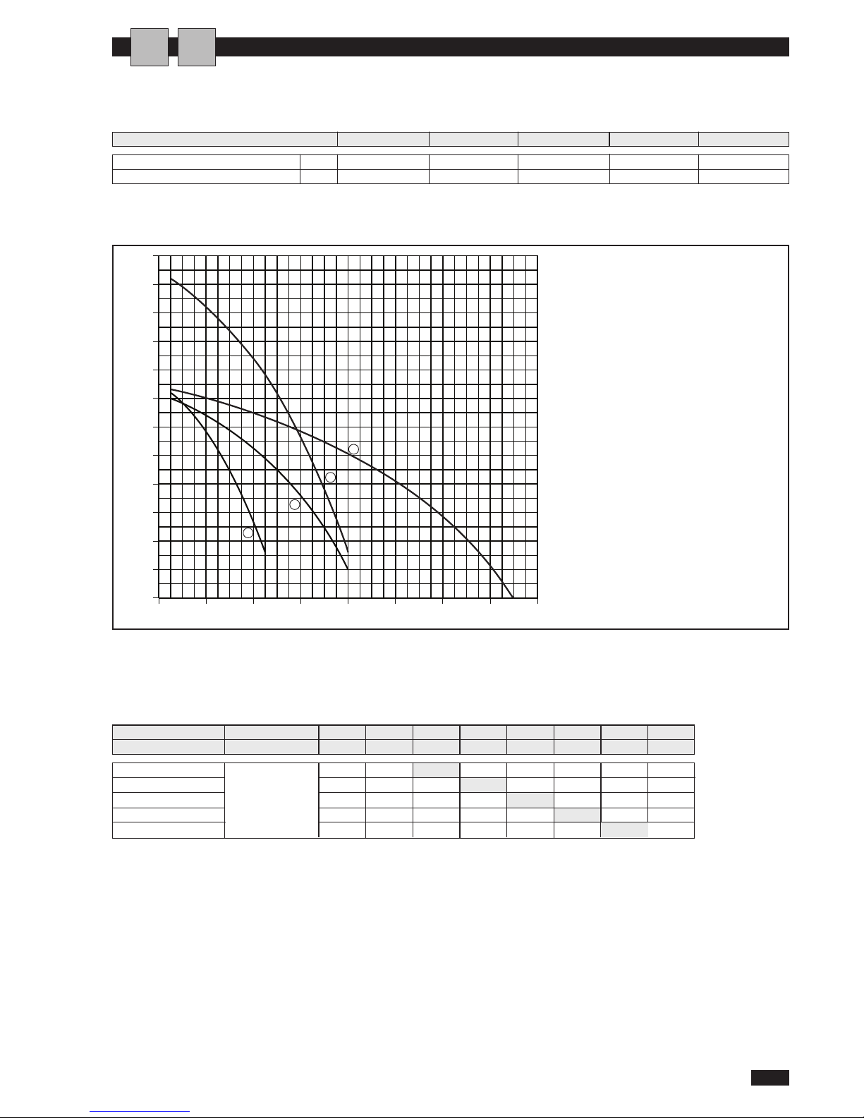
HYDRAULIC DATA
Minimum water content MICS Litri 55 69 96 118 135
Minimum water content MICS-N Litri 71 91 118 150 168
1
2
0246810121416
50
75
100
125
150
175
200
225
250
275
300
325
350
3
4
Model 0072 0092 0122 0152 0182
(
1) MICS/MICS-N 0072
(2) MICS/MICS-N 0092 MICS 0122
(
3) MICS-N 0122 MICS 0152
(4) MICS-N 0152 MICS/MICS-N 0182
USEFUL PUMP HEAD CURVES (*)
(*) To obtain the useful head of the installation, subtract the pressure drop of the plate heat exchanger
MINIMUM WATER CONTENT
I
A
Model Water m3/h 3,0 3,1 4,0 5,5 6,8 7,7 8,0
flow l/sec 0,83 0,86 1,11 1,53 1,89 2,14 2,22
HEAT EXCHANGER PRESSURE DROP (WATER SIDE)
Note: the values highlighted refer to the rated flow
evaporator water in/out IN/OUT 7/12° C
condenser air in 35°
0072 kPa 32 34 ----0092
Pressure
kPa - 21 35 ----
0122
drop
kPa - 14 22 42 64 82 0152 kPa --17 31 48 62 66
0182 kPa ---24 37 48 52
Page 20
MICS / MICS-N
18
English 07/07
CHECKING AND STARTING UP THE UNIT
PREPARING FOR FIRST START UP
or restarting after shutting down for long periods.
T
he chiller must be started up for the first time by the
Technical Service.
Before starting up the chillers, make sure that:
- All safety conditions have been respected
- The chiller is adequately fixed to the surface it rests on
- Functional distances have been respected;
- Hydraulic connections have been carried out as indicated
in the instruction manual
- The water circuit is filled and vented;
- The water circuit valves are open
- Electrical connections have been carried out correctly
- Voltage is within a tolerance of 10% of the rated voltage
for the unit
- The unit is correctly earthed
- All electrical and hydraulic connections are tight and have
been completed correctly.
The unit must be started up for the first time with
s
tandard settings. Set point values may be modified
only after testing has been completed. Before starting
up, power the unit for at least two hours by switching
QF1 and QS1 to ON and setting the control panel
“HSW7” to OFF to allow the oil in the compressor
sump to heat up.
A
I J
LKABCDE
F
G
H
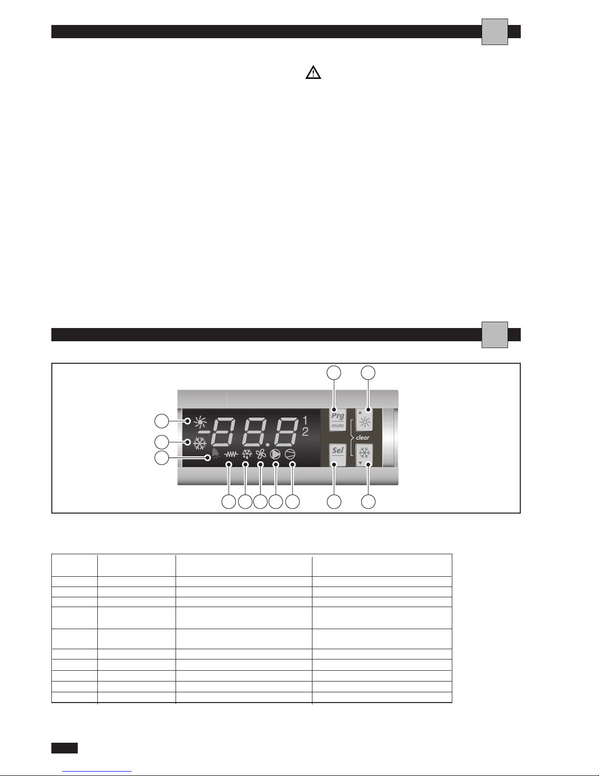
HSW8
INTERFACCIA UTENTE
A
DISPLAY SYMBOLS
symbol
colour Meaning Meaning
with indicator light on with indicator light blinking
1; 2 amber compressor 1 or 2 on richiesta di accensione
3; 4 amber compressor 3 or 4 on
A amber at least one compressor on
B amber pump/fan for outflowing air on
C amber condensation fan on
D amber condensation fan
E amber defrost active
F red alarm active
G amber chiller mode
H amber heat pump mode
Page 21
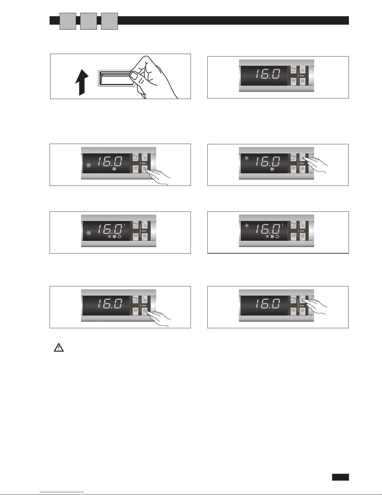
ACTIVATING AND DEACTIVATING THE UNIT
- Put the on/off switch to ON
Cooling mode:
- To switch on the cooling mode, keep button K pressed for 5
sec.The mode of operation and the pump indicator lights come
on.
One or both compressors may activate according to the temperature of the return flow of water.
Turning off:
To turn off the unit in the cooling mode, keep button K pressed
for 5 sec.
At every change of season, make sure the operating
conditions fall within the limits specified on page 16.
Check that the compressor current input is less than
the maximum indicated in the table of technical data.
In three-phase models, check that the noise levels
of the compressor are not abnormal. If this is the case,
reverse one phase.
Make sure the voltage is within the established limits
and that, for three phase units, the unbalance between
the phases is less than 3%. Check that the cover is
closed again following the setting procedure
- The temperature of the water returning from the system
appears on the display:
Heating mode:
- To switch on the heating mode, keep button J pressed for 5
sec.The mode of operation and the pump indicator lights come
on.
One or both compressors may activate according to the temperature of the return flow of water.
To turn off the unit in the heating mode, keep button J pressed
for 5 sec.
MICS / MICS-N
19
English 07/07
HSW8
HSW8
HSW8
HSW8
HSW8
HSW8
HSW8
ON
O
FF
A
CTIVATING AND DEACTIVATING THE UNIT
U A
I
Page 22
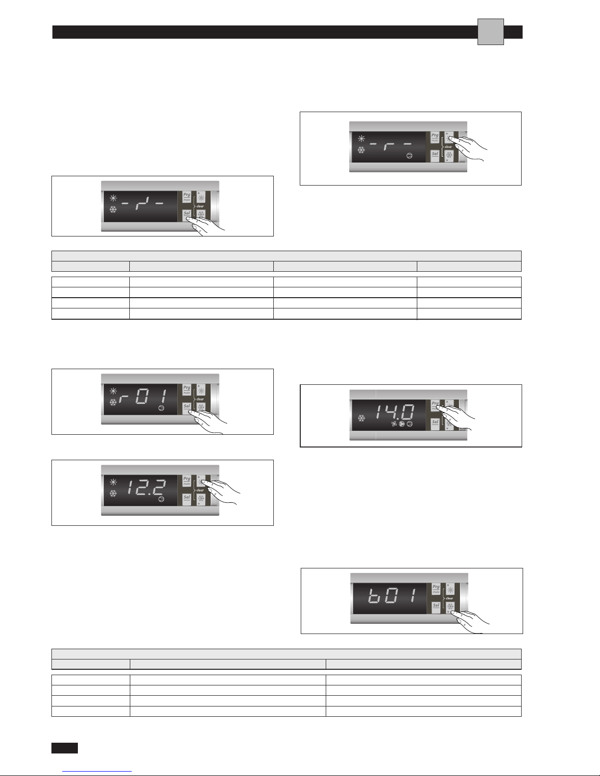
READING OF SENSOR VALUES
The following values may be displayed by pressing button
J for 1 sec and scrolling with button J or K:
Press button L to change a parameter
After having displayed the current value, use buttons J and
K to change it.
Then press button I to exit without saving the change or
button L to save the change.
Lastly press button I to return to the upper level menus
or to exit from the configuration menu.
MICS / MICS-N
20
English 07/07
IMPOSTAZIONE PARAMETRI SERVICE
A
SETTING THE SET POINTS
T
he factory Set Point settings are: cooling 12°C, heating
40°C.
To modify the set points, proceed as follows:
- Press button L for 5 sec. to access the main parameters
window.
-
Use button J or K to scroll to the “parameters R” submenu.
Press button L to access the “parameters R” submenu
and use button J or K to scroll the accessible parameters of this menu:
r01 COOL set point °C 12
r02 COOL C1/C2 ON/OFF differential °C 3
r03 HEAT set point °C 40
r04 HEAT C1/C2 ON/OFF differential °C 3
LIST OF ACCESSIBLE PARAMETERS
Parameter Description Unit of measure Factory set point
Note: when setting the parameters the COMPRESSOR and HEATER LEDs will flash alternating with the DEFROST LED.
HSW8
HSW8
HSW8
HSW8
HSW8
HSW8
b01 water outlet temperature °C
b02
water inlet temperature °C
b04
high pressure value
b09 low pressure value
LIST OF ACCESSIBLE PARAMETERS
Parameter Description Unit of measure
Page 23
MICS / MICS-N
21
English 07/07
D
ISPLAYING ALARMS
I A
FAULT CAUSE REMEDY
Values display indication
HP1
High pressure switch tripped
Check fault
Reset the switch
Values display indication
LP1
Low pressure switch tripped
(automatic reset)
Check fault
Values display indication
A1
Compressor thermal cut-out tripped
(manual reset)
Check water outlet temperature
Check water flow
Check set point temperature
Values display indication
E2
Water delivery sensor BT2 malfunction
(automatic reset)
Check electrical connections
Replace component
Values display indication
E4
Coil sensor BT3 malfunction
(automatic reset)
Check electrical connections
Replace component
Values display indication
E1
Water return sensor BT1 malfunction
(automatic reset)
Check electrical connections
Replace component
Values display indication
FL
Differential pressure switch or flow switch
tripped
(automatic reset)
Check for inadequate water flow
Check presence of air in water circuit
Page 24

MICS / MICS-N
22
English 07/07
O
PERATING CHARACTERISTICS
Set point in cooling
(
factory setting) = 12°C, differential = 3°C.
With outlet water temperatures above 13.5°C, the 1st
compressor activates, whereas with temperatures above
15°C, the 2nd compressor activates.
With water temperatures below 13.5°C, the 1st compressor switches off, whereas with temperatures below 12°C,
the 2nd compressor switches off.
Set point in heating
(factory setting) = 40°C, differential = 3°C.
With outlet water temperatures above 38.5°C, the 1st
compressor activates, whereas with temperatures above
37°C, the 2nd compressor activates.
With water temperatures below 38.5°C, the 1st compressor switches off, whereas with temperatures below 40°C,
the 2nd compressor switches off.
In the event of a temporary power failure, when power
returns, the mode set previously will be retained in the
memory.
COMPRESSOR START UP DELAY
Two functions prevent the compressor from starting up
too frequently.
- Minimum time since last shut-down 180 seconds.
- Minimum time since last start-up 300 seconds.
- Minimum time of operation for each compressor 60 sec.
- Minimum time for 2nd compressor ON from 1st compressor ON is 360 seconds.
- Minimum time for 2nd compressor OFF from 1st compressor OFF is 20 seconds.
PUMP
The electronic board has an output for control of the circulating pump, which starts up when the unit is switched
on in either the cooling or heating mode and switches off
60 seconds after the unit has been switched off.
The water flow alarm functions (differential pressure switch and water flow switch) are activated after the first 20
seconds of pump operation, when the water flow is regular.
FAN SPEED CONTROL
For correct operation of the unit with different outside
temperatures, the microprocessor controls the fan speed
based on the pressure reading from the pressure transducer, thus enabling heat exchange to be increased and/or
decreased, maintaining the condensing or evaporation
pressures practically constant.
The fan functions independently of the compressor.
FROST PREVENTION ALARM
T
o prevent breakage of the plate-type heat exchanger due
to freezing of the water inside it, the microprocessor provides for activation of the anti-frost heater if the temperature measured by the exchanger outlet temperature sensor is below +4°C and stopping of the compressors if the
temperature is below +3°C.
This anti-frost temperature setting can be changed solely
by an authorized service centre and only after having
checked that there is antifreeze solution in the water circuit.
Activation of this alarm causes the compressor to stop and
not the pump, which remains in operation.
To reset normal functions, the outlet water temperature
must rise above +7°C; reset is manual.
WATER FLOW ALARM
The microprocessor provides for management of a water
flow alarm controlled by a differential pressure switch fitted as standard on the appliance and a flow switch to be
installed on the water delivery piping.
Tripping of this alarm shuts down the compressor but not
the pump, which remains active.
AI
Page 25
MICS / MICS-N
23
English 07/07
Regular maintenance is fundamental to maintain the efficiency of the unit both in terms of operation and energy
consumption.
The Technical Assistance Service maintenance plan must be
observed, with an annual service which includes the following operations and checks:
- Filling of the water circuit
- Presence of air bubbles in the water circuit
- Efficiency of safety devices
- Power supply voltage
- Power input
- Tightness of electrical and hydraulic connections
- Condition of the compressor contactor
- Checking of operating pressure, superheating and subcooling
- Cleaning of finned coil
- Cleaning of fan grills
- Mesh filter cleaning (compulsory)
For units installed near the sea, the intervals between
maintenance should be halved.
CHEMICAL WASHING
You are recommended to chemically wash the plate heat
exchanger after every 3 years of operation. For instructions on how to carry out this operation, contact De’
Longhi Spa.
REFRIGERANT GAS CONTENT
The chillers are filled R410A refrigerant gas and tested in the factory. In normal conditions, there should be no need for theTechnical
Assistance Service to intervene to check the refrigerant gas. However, over time,small leaks may develop at the joints leading to loss
of refrigerant and draining of the circuit,causing the unit to function
poorly. In this case, the leaks of refrigerant must be identified and
repaired and the refrigerant circuit refilled. Proceed as follows:
-
Empty and dry the entire refrigerant circuit using a vacuum
pump connected to the low and high pressure tap until the
vacuometer reads about 10 Pa. Wait a couple of minutes and
check that this value does not rise to more than 50 Pa.
- Connect the refrigerant gas cylinder or a filling cylinder
to the low pressure line pressure gauge connection.
- Fill with the quantity of refrigerant gas indicated on the
rating plate of the unit.
- Always check the superheating and subcooling values. In
the nominal operating conditions for the appliance, these
should be between 4 and 8°C respectively.
In the event of partial leaks, the circuit must be
completely emptied before being refilled.
The refrigerant must only be filled in the liquid state.
Operating conditions other than nominal condi-
tions may produce considerably different values.
Seal testing or identification of leaks must only be
carried out using R410A refrigerant gas, checking
with a suitable leak detector.
The refrigerant circuit must not be filled with a
refrigerant other than R410A. The use of a refrigerant
other than R410A may cause serious damage to the
compressor.
Oxygen, acetylene or other flammable or poisonous gases must never be used in the refrigerant
circuit as they may cause explosion.
Oils other than those indicated on page 12
must not be used. The use of different oils may
cause serious damage to the compressor.
SHUTTING DOWN FOR LONG PERIODS
After deactivating the chiller:
- Make sure the remote switch SA1 (if present) is in the
"
OFF" position.
- Make sure the remote keyboard (if present) is set to “OFF”.
- Position QF1 and QS1 on OFF
- Deactivate the indoor terminal units by placing the
switch of each unit in the “OFF” position.
- Close the water valves
If there is a possibility that the outside temperature may drop below zero,there is the risk of freez-
i
ng.
The water circ u it MUS T BE EMP TIED AND
CLOSED or antifreeze must be added in the proportion recommended by the manufacturer.
ROUTINE MAINTENANCE
EXTRAORDINARY MAINTENANCE
A
A
A
Page 26
MICS / MICS-N
24
English 07/07
TROUBLESHOOTING
AI
F
AULT CAUSE REMEDY
No voltage
Supply voltage too low
Mains switch in OFF position
R
emote switch (if present) in OFF position
Control panel set to OFF
Main unit switch in OFF position
Compressor thermal solenoid switch OFF
- Check presence of voltage
-
Check safety systems upstream
of the appliance
Check power line
Switch ON
Contactor coil faulty
E
lectronic board faulty
Start-up capacitor faulty (if present)
Compressor faulty
Replace the component
Check
Replace the component
Check
Check
Check
The compressor stops due
to the activation of the
protection devices
Excessive discharge pressure
Low suction pressure
Low voltage
Electrical connections not sufficiently tight
Operation outside permitted limits
Faulty operation of pressure switches
Check supply voltage
Check electrical insulation of
windings
Thermal cut-out tripped
Insufficient output
Insufficient refrigerant
Sizing of unit
Operation outside recommended limits
Noise and vibrations
Contact between metal bodies
Repair
Weak foundations
Tighten screws
Loose screws
Compressor noisy
Liquid returning to compressor
Inadequate fixing
Reverse one phase
Reversed phase (three phase units only)
The chiller does not
start up
Page 27
MICS / MICS-N
25
English 07/07
FAULT CAUSE REMEDY
*Values indicative only
Low suction pressure
(less than 0.62 MPa)*
Low utility water inlet temperature
Low external water inlet temperature
Thermostatic expansion valve faulty or blocked
Clogged water filter
Blocked plate heat exchanger
Check
Low discharge pressure
(less than 1,8 MPa)*
Low outside air temperature
Low water inlet temperature
Check
Air in water circuit
Vent air
Insufficient gas content
Check
Moisture in the refrigerant circuit
(liquid indicator - moisture yellow)
Empty and refill
Faulty fan regulation
Check
High suction pressure
(greater than 1,7 MPa)*
High outside air temperature
High inflow water temperature
Thermostatic expansion valve faulty or excessively open
Check
High discharge pressure
(
greater than 3,5 MPa)*
High external water temperature
High water inlet temperature
I
nsufficient water flow
Insufficient air flow
Check fan operation
Check pump operation
Faulty fan regulation
Check
Air in water circuit
Vent air
Excessive refrigerant charge
Check
Page 28

MICS / MICS-N
26
English 07/07
USEFUL INFORMATION
U I A
For information on technical assistance and obtaining spare parts, contact
FIXED AIR-CONDITIONINGTECHNICAL SERVICE DEPARTMENT,
C
LIMAVENETA HOME SYSTEM SRL
v
ia. L. Seitz, 47 - 31100 Treviso (ITALIA)
www.climaveneta.it
[email protected]
Page 29

MICS / MICS-N
27
English 07/07
Page 30

Page 31

Page 32

Dé Longhi Group - Via L. Seitz, 47 - 31100 Treviso (Italia)
COD.578016900
 Loading...