

Page 1
GB
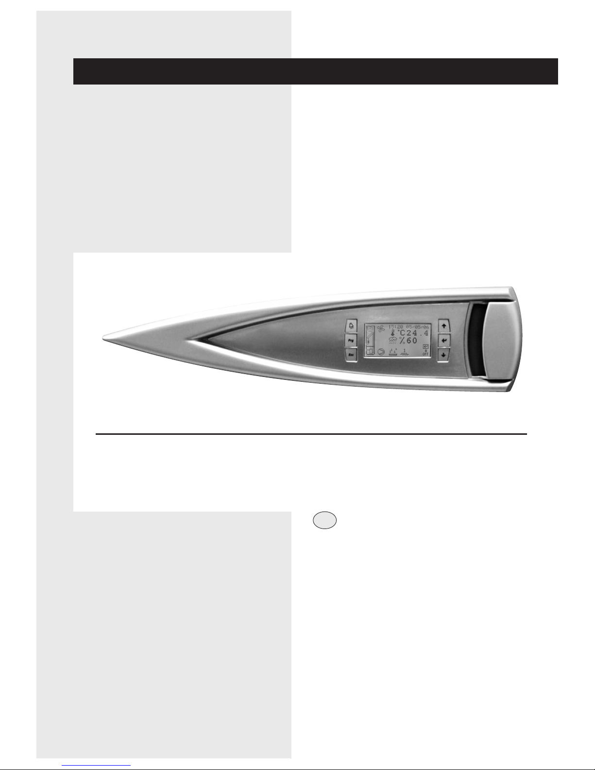
INSTRUCTION MANUAL
USER TERMINAL:
EVOLUTION
Page 2

Page 3
1
English
TERMINAL EVOLUTION
CONTENTS
General characteristics 2
User interface 2
Main screen 3
Flow charts for accessing the screens 7
Default values 11
Diagram of ambient temperature control 12
Diagram of ambient humidity control 13
General information and definitions 14
Most common configurations 15
Electrical connections 16
Connection between pC01 boards 16
LAN connection between 2 or more units 17
Connections to the remote terminal from the board 18
Configuration of the terminal and the board 19
Displaying the network from the terminal 20
Troubleshooting 21
U I A
U I A
U I A
U I A
U I A
U I A
U I A
U I A
U I A
U I A
U I A
U I A
U I A
U I A
U I A
U I A
AIU
In some parts of this manual, the following symbols are used:
WARNING = for actions that require special care
and suitable preparation
PROHIBITED = PROHIBITED
A
I
U
The following symbols are used in this publication and inside the unit:
User
Installer
Assistance
Important
Prohibition
Specialist personnel
(electrician)
Person with in-depth knowledge
and experience such as to be
able to recognise risks and avoid
dangers that may derive from
electricity (IEV 826-09-01).
Page 4
TERMINAL EVOLUTION
2
English
GENERAL CHARACTERISTICS
The EVOLUTION controller allows independent control of all the unit
operating parameters.
The controller is made up of:
• A microprocessor control board housed inside the electrical panel
• A user terminal or graphic interface
The program that resides on the control board can be used on all types
of precision air-conditioning units, specifically:
• direct expansion units, water cooled or air cooled;
• water chiller units;
• direct expansion units with energy saving function;
• dual cooling units.
The main functions of the program are:
• management of the temperature and humidity in civil or technological
environments;
• management of 1 or 2 scroll compressors
• management of between 1 and 3 electric heating stages for heating
and post-heating;
• management of modulating valves for cooling using cold water and
heating using hot water;
• management of the evaporator fan speed, when featured;
• management of an external or built-in immersed electrode humidifier;
• outlet temperature control;
• management of alarms and maintenance warnings;
• logging of up to 100 alarm events;
• management of the safety running time for each components;
• unit on/off from user terminal, remote contact, supervisory system
and according to time bands;
• local network (LAN) connection for managing backup units;
• connection to local supervision networks and BMS (LonWorks,
BACnet, Modbus…..).
Throught the user terminal you can view and modify (by using a passaword) all following datas:
• values read by the probes and the corresponding calibration;
• active alarms, alarm log, configuration of the alarm digital outputs;
• configuration of the local network (LAN);
• parameter settings for serial communication with the supervisory
system;
• configuration parameters and fundamental control parameters;
• operating hours and number of starts of the controlled devices;
• clock settings;
• selection between the different languages available.
Using the local network connection, the program can manage the following additional functions:
• Automatic rotation by time or event, for 1 or 2 units in stand by
mode, between max 10 units connected in LAN
• management of the average temperature and humidity readings from
a maximum of 10 units;
• use of just one terminal to control a maximum of 10 units;
In order to protect the program default settings, the software features
two levels of password, USER for the main user settings, and FACTORY
for the authorised technicians, used to modify and reset all the software
parameters.
The user interface is made up of:
• 11x15 pixel backlit LCD;
• 6 backlit buttons for scrolling and modifying the parameters.
The microprocessor board is connected to the user interface
using a 4-pin telephone cable with RJ11 jack.
AIU
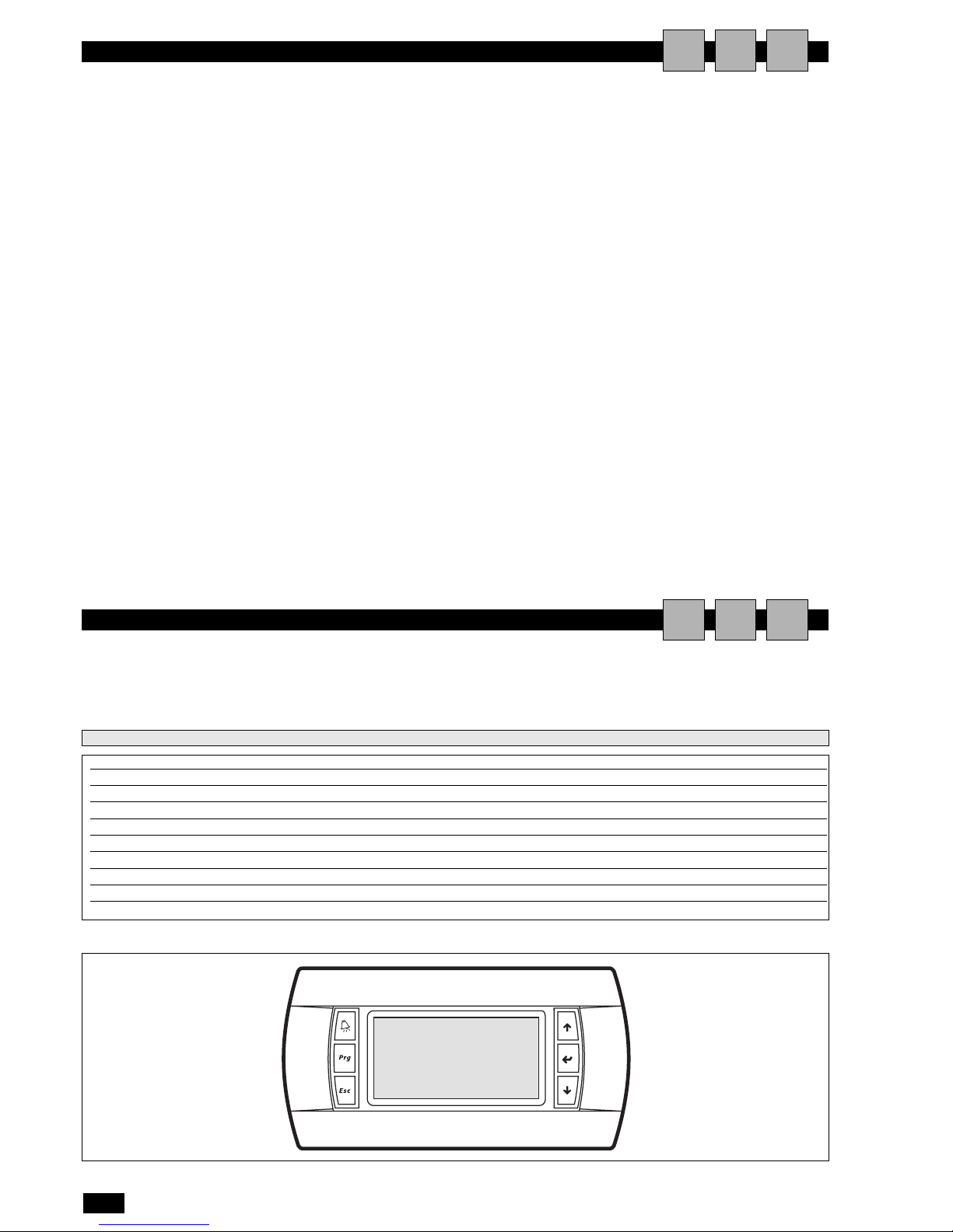
USER INTERFACE
ALARM button functions:
• reset the alarm (if hold for 5 seconds)
• flashes red in the event of active alarms
• to stop buzzer durino an alarm
button PRG:
access the configuration menu
button ESC:
exit the screens
button UP functions:
• scroll and/or change screen
• modify the values
• to move inside the manù
button ENTER functions:
• confirm the modifications
• access the areas for modification
button DOWN functions:
• scroll and/or change screen
• modify the values
• scroll inside the menus
AIU
Power supply from the power board through telephone cable (cod. S90CONN00*) or from external source 18 to 30 Vdc through TCONN6J000
Power input PGD1: 1.2 W;
Operating conditions -20T60 °C, <90% rH non-condensing
Storage conditions -30T70 °C, <90% rH non-condensing
Index of protection IP65 with panel mounting, IP40 with wall mounting
Resolution 132X64
Back-lighting green LED
Buzzer NOT AVAILABLE
Row number 8
pLAN default
Technical features
Page 5
unit off
unit on
TERMINAL EVOLUTION
3
English
MAIN SCREEN
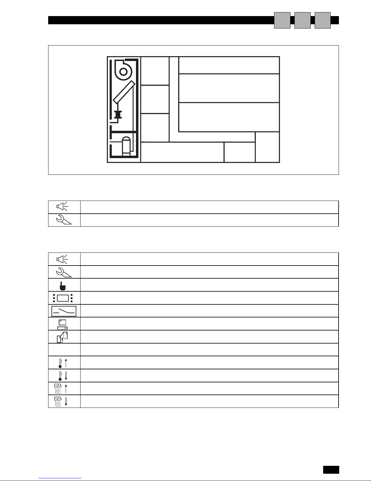
The following figure shows the layout of the main screen.
Area 1 - GENERAL STATUS OF THE UNIT.
AIU
1
2
3
48
9
7
6
5
presence of an active alarm (flashing)
maintenance signal (flashing)
manual controls active (flashing)
unit on/off from terminal (flashing)
unit on/off from remote contact (flashing)
unit on/off from supervisory system (flashing)
unit on due to emergency via the network (LAN) (flashing)
Unit in stand-by (flashing)
Unit ON for High Temperature Limit overcoming (flashing)
Unit ON for Low Temperature Limit overcoming (flashing)
Unit ON for High Humidity Limit overcoming (flashing)
Unit ON for Low Humidity Limit overcoming (flashing)
Area 2 - DETAILED INDICATION OF THE UNIT STATUS.
STAND
BY
Page 6
4
English
TERMINAL EVOLUTION
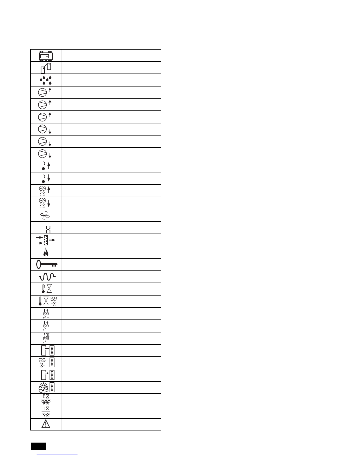
EEPROM fault
LAN disconnected
Water leak (flood)
High pressure in circuit 1
High pressure in circuit 2
High pressure
Low pressure in circuit 1
Low pressure in circuit 2
Low pressure
High ambient temperature
Low ambient temperature
High ambient humidity
Low ambient humidity
Air flow alarm
Incorrect phase sequence
Filters blocked
Fire/smoke detected
Wrong password (5 attempts)
Electric heater overheat
High water temperature
High water temperature during dehumidification
High humidifier current
Low humidifier current
No water in humidifier
Room temperature probe fault
Room humidity probe fault
Outlet air temperature probe fault
Outside air temperature probe fault
Cold water temperature probe fault
Hot water temperature probe fault
Emergency mode active
Area 3 - ALARMS LIST
This area displays an icon that, in the event of alarms or maintenance signals, respectively indicates the type of alarm and the device that
requires maintenance.
1
2
1
2
L1L2L3
EVENT OF ALARM
In case of Alarm event:
• Acoustic signalling is activated (buzzer);
• Red led under the alarm button s activated;
• Green leds on main screen are activated
• AREA 2 on main screen is showing the alarm icon;
• AREA 3 on main screen visualized an icon who represent the
kind of active alarm .
With a single press on the alarm button the acoustic signalling is
de-activated.
RESET OF ALARM STATUS
To make the ALARM RESET, we split the alarms in 3 different
kind:
• Alarms with only Automatic Reset:
in this category we found only the alarm “LAN DISCONNECTED”.
• Alarms with Automatic/Manual Reset (based on the customer's
settings on screen I3); in this category we found:
- Ambient Temperature Limits overcoming
- Ambient Humidity Limits overcoming
- Chilled Water too high
- Water Flow missing
- Low Pressure alarm
- Humidifier alarm
- Air filter alarm
By default alla bove are setted with AUTOMATIC RESET.
• Alarms with only Manual Reset:
After removing the alarm cause, it's required to push alarm button for few seconds to remove completely the alarm signalling
and will desappear any Alarm icon from AREA 2 and AREA 3.
With “Wrong Password Alarm”, the RESET is only manual after
the right input of the correct password.
ALARM LIMITS
With User Password (screens “I”): it's possibile to modify the
alarms limits setted like,Ambient Temperature Limits overcoming,
Ambient Humidity Limits overcoming, Chilled water too high( 2
limits: 1 for standard functiuoning, 2 for dehumidification functioning) anyway based on unit configuration.
ALARMS OUTPUTS
With User Password (screens “I”): it is possible to configure the
alarms output available on the main board. Based on unit configuration we can have 1 Alarm output (marked A) or 2 Alarm outputs (marked A & B).
We can also set:
• Status of Alarm Contacts (normally Open or Closed in OFF
position: in this second case we can also raise the “power missing alarm”);
• Address the desire alarm in contact A or B , depending on
customer choice.
Page 7
5
English
TERMINAL EVOLUTION
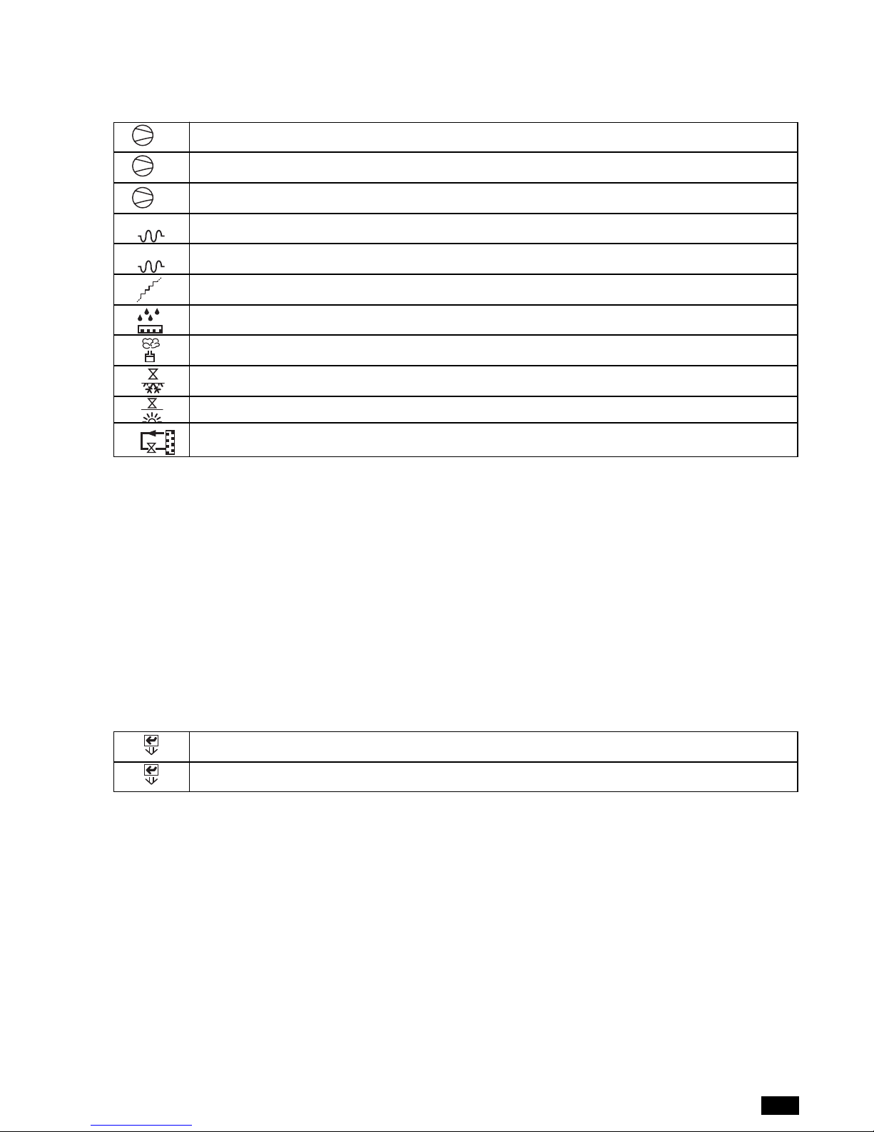
compressor 1 active
compressor 2 active
compressors 1 and 2 active
first electric heater stage active
second electric heater stage active
first and second heater stages active (third stage active)
Dehumidification active
Humidification active
Cold water valve open
Hot water valve open
Hot gas active
Area 4 ACTIVE COMPONENTS
This area displays icons corresponding to the devices currently installed on the unit.
1
2
2
1
2
1
1
2
Area 5
This area displays the time and date, if the clock board is fitted.
Area 6
This area displays the room temperature currently read by the probe on the unit (even if the control is enabled based on the average of
the values read by the units connected in the LAN).
Area 7
This area displays the relative humidity currently read by the probe on the unit (even if the control is enabled based on the average of the
values read by the units connected in the LAN).
Area 8
This area indicates the LAN address of the unit, if connected to other units.
Area 9
This area indicates the unit on/off mode from the user terminal.
press ENTER to switch the unit off
press ENTER to switch the unit on
ON
OFF
Page 8

6
English
TERMINAL EVOLUTION
STATUS SCREENS
Starting from the main screen, pressing the UP/DOWN buttons
accesses the other status screens, which are, in order:
A
WATER VALVE STATUS/OPTIONAL PROBE READINGS:
screen displaying the temperature values read by the
optional probes (outlet air temperature probe, chilled water
temperature probe, hot water temperature probe, outside air
temperature probe) and the percentage of opening of the
cold and hot water modulating valves;
B
LAN STATUS:
screen displaying the status of all the units
connected in the LAN;
C
HUMIDIFIER STATUS: screen displaying the status of the
humidifier, with all the technical operating values;
D
SET POINTS: screen displaying the active control set point;
from this screen, pressing PRG and entering the first level
password, accesses a further screen used to modify the set
point and proportional band corresponding to each type of
active control (cooling, heating, dehumidification, humidification);
E
OPERATING HOURS:
screen displaying the total operating
hours of the devices installed on the unit; from this screen,
following the instructions shown on the display and after
entering the first level password, the operating hours for each
device can be reset (set to zero), or the thresholds for activating the maintenance signal can be changed;
F
NUMBER OF STARTS: screen displaying the total number
of activations for the devices installed on the unit; from this
screen, following the instructions shown on the display and
after entering the first level password, the number of starts
for each device can be reset
G
LOG ACCESS: screen for accessing the display of the alarm
log;
H
SOFTWARE INFO: screen displaying information on the
software installed.
Page 9
7
English
TERMINAL EVOLUTION
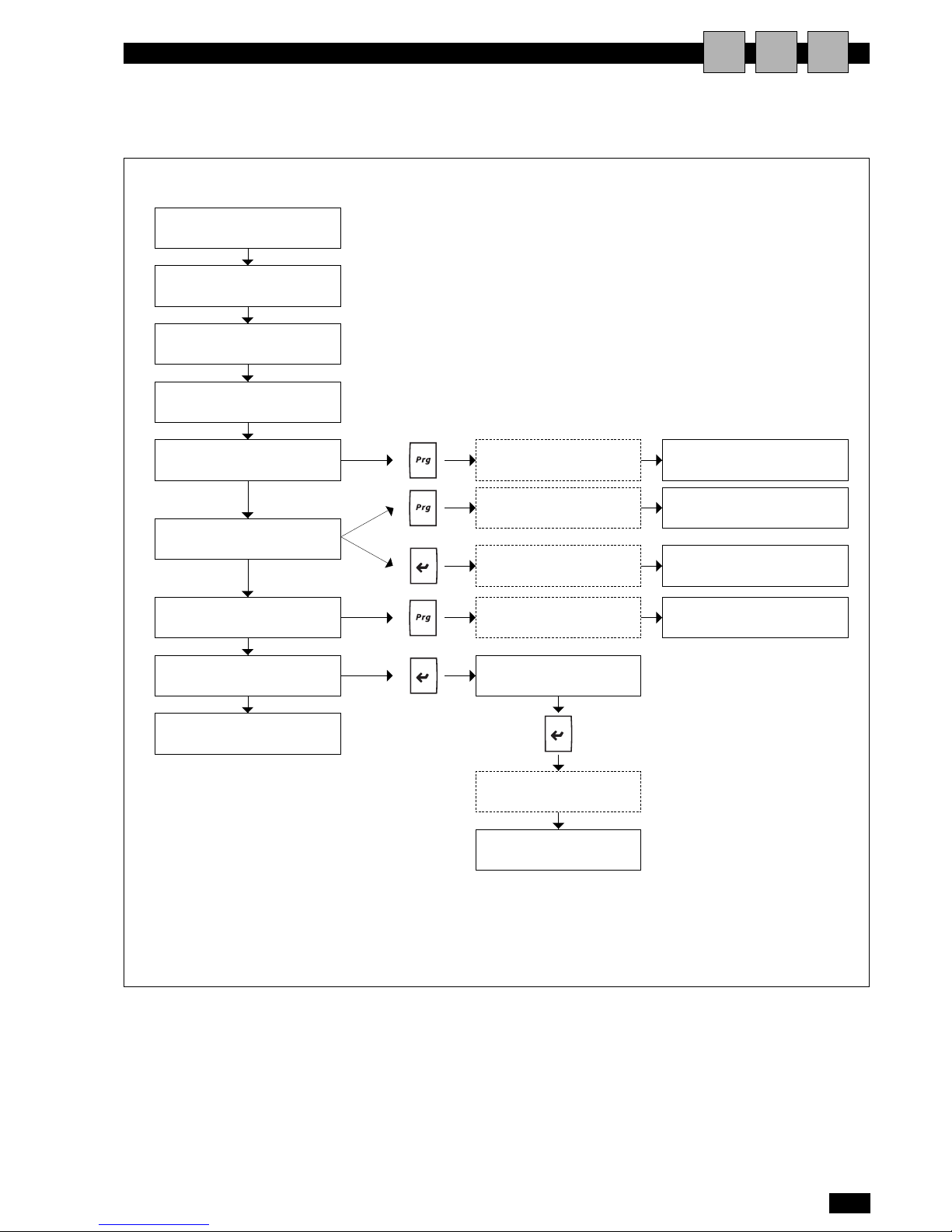
FLOW CHARTS FOR ACCESSING THE SCREENS
AIU
MAIN SCREEN
Water valve status
Optional probe readings
LAN status
Humidifier status
Set points
Operating hours
Number of starts
Log access
Software INFO
MAIN LOOP SCREENS
User PASSWORD
Change set point
Change proportional band
User PASSWORD Reset number of starts
Display alarm log
Manufacturer PASSWORD
Delete alarm log
User PASSWORD Change maintenance threshold
User PASSWORD Reset operating hours
A
B
C
D
E
F
G
H
NB: le maschere sopra indicate riportano al loro interno
solo indicaziioni ad icone grafiche
Page 10

8
English
TERMINAL EVOLUTION
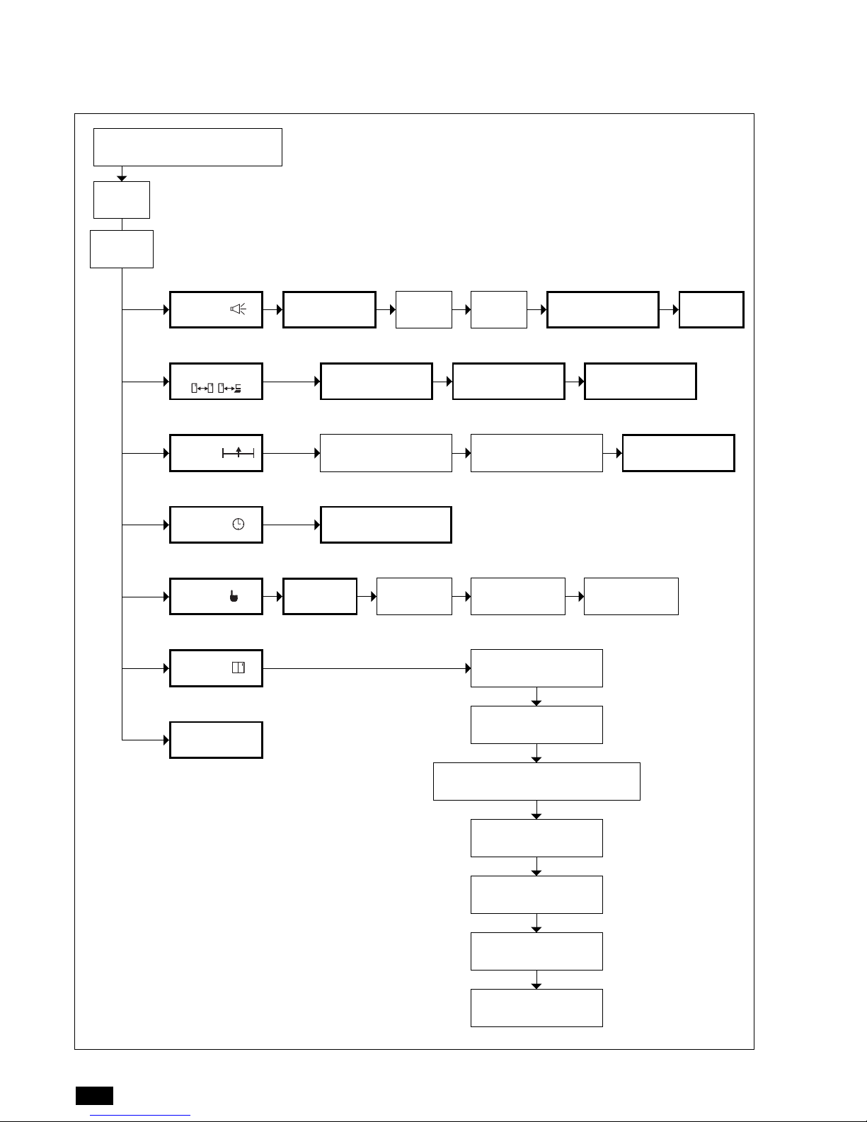
SCREENS FOR SETTING THE PARAMETERS
Starting from the main screen, pressing the PRG button and
entering the correct password accesses a menu used to set all
the other parameters that are not available on the status screens,
as described in the previous paragraph.
Two passwords can be entered:
• User password: accesses the user parameters, that is, the
parameters considered as being useful and easy to understand for the user;
•Manufacturer password: accesses all the parameters, that
is, both the user parameters and the manufacturer parameters.
The complete menu items are as follows:
I SETUP (alarms setting):
this menu is used to set the thresholds for the limit alarms
(high and low ambient temperature, high and low ambient
relative humidity, high water temperature), the delays for
some alarms, the type of reset (automatic or manual) for
some alarms, and the addresses of the alarm digital outputs
available on the controller;
L SETUP (LAN/serial/modem):
(user password)
this menu is used to configure the local network (LAN) and
set all the corresponding parameters, as well as the serial
communication parameters;
M SETUP (control settings):
(manufacturer password)
this menu is used to manually control all the devices on the
unit, disabling normal automatic control;
N SETUP (clock setup) :
(user password)
this menu is used to set the current time and date, if the
clock board is fitted;
O TEST/ (test/manual control):
(manufacturer password)
settings that involve the configuration of the unit, that is, the
devices, probes and sensors on the unit; : it is also possibile to
check the status of each single contact ( INPUT & OUTPUT)
of the main board;
P SETUP (unit configuration):
(manufacturer password)
this menu is used to modify some critical parameters that are
part of the control algorithm inside the control system;
Q DEFAULT SETUP:
(manufacturer password)
this menu is used to restore the default parameter values;
important: this operation also deletes the alarm log (this can
also be deleted on the screen displaying the log, as indicated
on the display and after entering the second level password),
while it does not cancel the basic configuration of the unit.
SCREENS “I”
Screen “I1”
Used to modify alarms limits for: ambient temperature, ambient
humidity & chillet water temperature.
Screen “I2”
Used to modify the alarms delay and in particular:
• Air flow alarm delay after fans starting
• Ambient temperature & Humidity alarm limits delay
• Air Filters alarm delay
• Low Pressare alarm delay after compressor starting
Screen “I3”
Used to set kind of RESET: Automatic or Manual (only for alarms
where it's allowed by manufacture)
Screen “I4”
Used to set STATUS of alarms contact
Screens “I5”,“I6”
Used to address the the alarm contact, type A or B.
SCREENS “L”
Screen “L1”
Used to set all parameters of LAN connection like:
• Number of units in LAN
• Temp. and Humidity averange value mode activated
• Abilitation of Stand by unit
• Rotation cycle time
• Number of Stand by unit (max 2 in case we have more than 4
units connected)
• Activation of Stand by unit for overcoming limits by Master
unit.
Screen “L2”
Used to modify regulation set-points on Stand by unit, is function
has been activated on screen L1
Screen “L3”
Used to modify all settings related to the serial connections.
SCREENS “M”
Screen “M1”
Used to set advanced parameters for temperature and humidity
control like:
• delay at start up after power back from failure
• Integral time
• Abilitation of air delivery sensor (when optino is required) and
relative set points.
Screen “M2”
Used to adjust the value read by Temp. sensors.
Screen “M3”
Used to modify the PASSWORD.
Page 11

9
English
TERMINAL EVOLUTION
SCREENS “N”
Screen “N1”
Used for clock settings
SCREENS “O”
Screen “O1” & “O2”
Used to activate manually the unit and also each single componenets installed on it.
Screen “O3” & “O4”
Used to check all contact available on board
SCREENS “P”
These screens are of foundamental importance for the right unit
functionig. Keep strong attention before to modify them, and eventually keep in contact with the manufacturer.
Any wrong use of this screens will make immediately decline any
warranty responsibility from the manufacturer.
Screen “P1”
Used to set the main importat/foundamental features of each unit
Screen “P2”
Used to set eventually optional sensors
Screen “P3”
Used to set the Remote ON-OFF via el. Contact and the time
costants values for water valves 3 points.
Screen “P4”
Used to modify parameters related to Electronic backward curved
EC Fans, like:
• Standard speed
• Energy saving speed when uniti s not in regulation.
Screen “P5”
Used to modify parameters related to Electronic backward curved
EC Fans, when it is related to 3 way chilled water valve.Then this is
screen is availavle only for AC* (chilled water unit).
Screen “P6”
Used to activate the Emergency Mode: when the dedicated contact
on the board activate the Emergency mode, only the components
reported inside this screen remain in ON, in order to save energy.
Screen “P7”
Used to modify and set Humidifier parameters.
Screen “P8”
Used to temporary disabling the Humidifier in order to provide its
maintenance or replacement.
Page 12
10
English
TERMINAL EVOLUTION
SETTING PARAMETERS SCREENS
MASCHERA
PRINCIPALE
RESET
MODE
ALARMS
DELAY
Temp. and
Humidity limits
SETUP
STANDBY UNIT
SETUP
LAN SETUP
SETUP
PasswordSENSORS ADJUSTMENT
ADVANCED
PARAMETERS
SETUP
PRG
password (*)
SERIAL SETUP
ALARMS OUTPUT
STATUS
A/B
SETUP
DIGITAL INPUT
STATUS
MANUALS
TEST
MANUALS
TEST
DIGITAL OUTPUT
S TATU S
CLOCK SETUP
SETUP
TEST/
Configuration unit type
SETUP
OPTIONAL SENSORS
DEFAULT
SETUP
Remote ON/OFF
VALVES PARAMETERS
EVAPORATING FAN
SETUP
EMERGENCY MODE
HUMIDIFIER TYPE
On bold are indicated all screens under User
Password.To join all other screens you must use the
manufacturer password.
I
L
M
N
O
P
Q
I1 I2 I3 I4
L1 L2 L3
L1
N1
O1 O2 O3
P1
O4
L2 L3
I5/I6
P2
P3
P4/5
P6
P7
HUMIDIFIER
MAINTENANCE
P8
Page 13
11
English
TERMINAL EVOLUTION
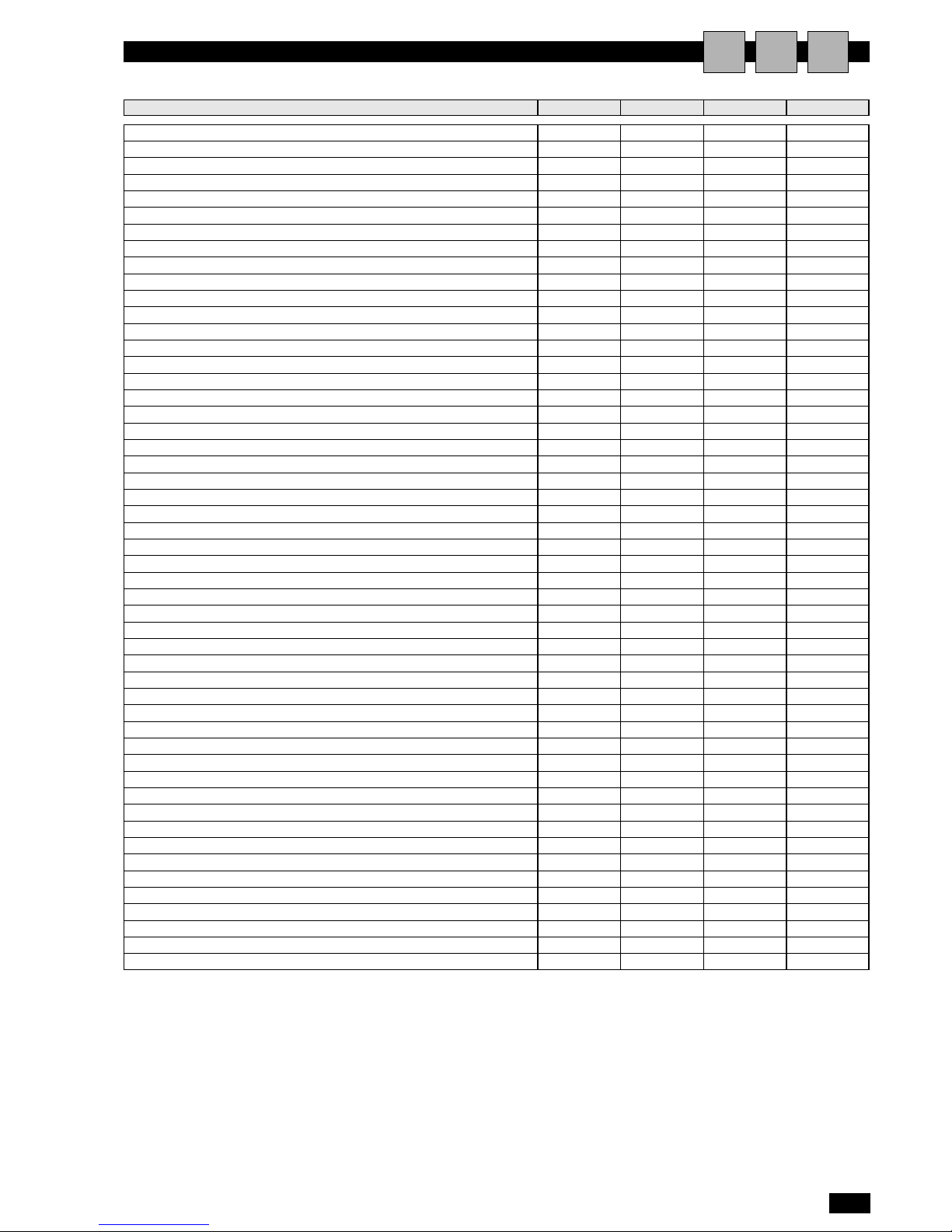
USER DEFAULT VALUES
AIU
Set points and differential band
Cooling set point °C 24 17 35
Cooling proportional band °C 1.5 0.5 9.9
Heating set point °C 24 12 30
Heating proportional band °C 1.5 0.5 9.9
Dehumidification set point % 55 45 90
Dehumidification proportional band % 5 3 15
Humidification set point % 45 10 55
Humidification proportional band % 5 3 15
Maintenance operating hour threshold
Fan h 00000 00000 32767
Compressor 1 h 00000 00000 32767
Compressor 2 h 00000 00000 32767
Heaters 1 h 00000 00000 32767
Heaters 2 h 00000 00000 32767
Humidifier h 00000 00000 32767
Alarm parameters
High ambient temperature threshold °C 32 20 50
Low ambient temperature threshold °C 10 0 30
High ambient humidity threshold % 80 30 99
Low ambient humidity threshold % 30 0 70
High water temperature threshold °C 15 5 50
High water temperature threshold in dehumidification °C 7 0 30
Flow alarm delay after unit start-up s 15 15 999
Alarm delays when exceeding temperature and humidity limits s 60 0 999
Blocked filter alarm delay s 8 2 999
Low pressure alarm delay after compressor start s 180 2 999
Reset temperature limit alarm Auto MAN Auto
Reset humidity limit alarm Auto MAN Auto
Reset high water temperature alarm Auto MAN Auto
Reset low pressure alarm Auto MAN Auto
Reset humidifier Alarm Auto MAN Auto
Reset water flow alarm Auto MAN Auto
Select alarm output A
LAN parameters
High temperature threshold to switch the unit on in standby °C 30 20 50
Low temperature threshold to switch the unit on in standby °C 18 0 30
High humidity threshold to switch the unit on in standby % 75 55 90
Low humidity threshold to switch the unit on in standby % 35 10 45
Serial parameters
Serial address 1
Serial baud rate baud 1200
Protocol Standard
Advanced control parameters
Unit start delay s 0 0 999
Control start delay after unit start-up s 60 20 999
Integration time s 900 0 999
Enable minimum outlet air temperature limit Y
Minimum outlet temperature limit set point °C 12 0 25
Enable dehumidification function Y
Hot water activation set point °C 40 20 99.9
U.M. DEFAULT MIN MAX
Page 14
12
English
TERMINAL EVOLUTION
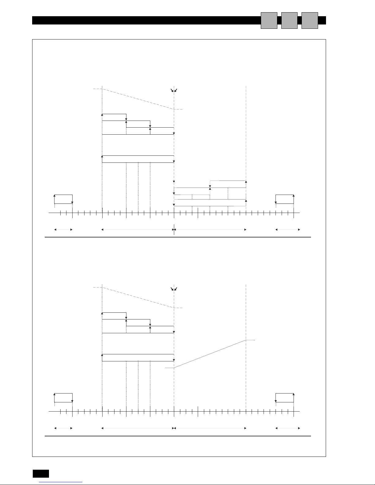
AMBIENT TEMPERATURE CONTROL DIAGRAMS
AIU
2. Chilled Water version (CW)
1. Direct expansion version (DX)
off
100%
0%
0%
100%
on
on
on
on
on
R3
R2
R1
R1
cooling
set point
heating set
point
off
off
10°C
2°C
fixed diff. heating diff. cooling diff. fixed diff.
1,5°C 1,5°C 2°C
22,5°C 24°C 25,5°C 28°C 30°C
off
off
cold water valve
hot water valve
low temperature
alarm
on
off
high ambient
temperature
ambient
temperature
off
off
on
on
on
0%
100%
on
on
on
on
on
R3
R2
R1
R1
C1
C1
C2
cooling
set point
heating
set point
off
off
off
10°C
2°C
fixed diff. heating diff. cooling diff. fixed diff.
1,5°C 1,5°C 2°C
21,5°C 22,5°C 24°C 25,5°C 28°C 30°C
off
off
hot water valve
low temperature
alarm
on
off
high ambient
temperature
ambient
temperature
Page 15
13
English
TERMINAL EVOLUTION
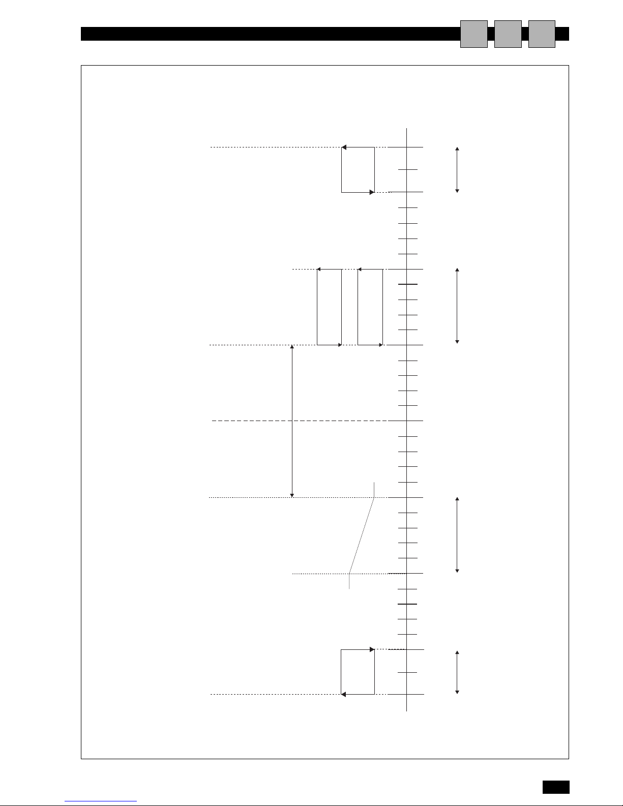
AMBIENT HUMIDITY CONTROL DIAGRAM
AIU
on
off
30% 33% 40% 45% 50% 55% 60% 77% 80%
3%
differential
dehumidification
set point
humidification
set point
Cold water valve
compressor
humidifier
100%
0%
off
off
on
on
10% DEAD ZONE
low ambient
humidity
alarm
on
off
high ambient
humidity
ambient
rH%
5%
differential
5%
differential
3%
differential
Page 16
14
English
TERMINAL EVOLUTION
GENERAL INFORMATION AND DEFINITIONS
AIU
1 The local network connection is used to manage the operation
of a series of air-conditioners operating inside the same environment, or a series of liquid chillers connected in parallel in
the same installation.
2 The max number of units that can be connected is 10.
3 The maximum extension of the network connections is 500
metres.
4 All the units connected in the network must have the same ver-
sion of the program installed in the flash memory on the board.
5 A terminal can be configured as "private" or "shared":
- a private terminal can display the operating status only of
the unit it is connected to via telephone cable;
- a shared terminal can display the operating status of all the
units connected in the network.
6 Each board can “talk” to a maximum of 3 terminals; in common
applications, generally no more than two are used:one fitted on
the unit and another optional remote terminal configured as
share terminal.
The priority on the remote share terminal is always the display of
the alarms, even if when the alarm is activated the terminal is displaying the parameters from another unit.
7 To be able to communicate over a local network, the units must
be configured so as to be able to send the other units the
required information for correct operation.
In this regard, the first step involves assigning a progressive
number to the different units (1, 2, 3,…10) and then correctly
setting the addresses of the various terminals and LAN boards,
and making the electrical connections, step-by-step, as
described in the following paragraphs.
Page 17
15
English
TERMINAL EVOLUTION
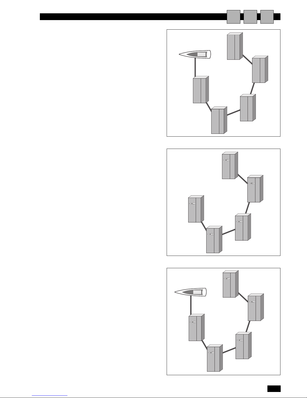
MOST COMMON CONFIGURATIONS
AIU
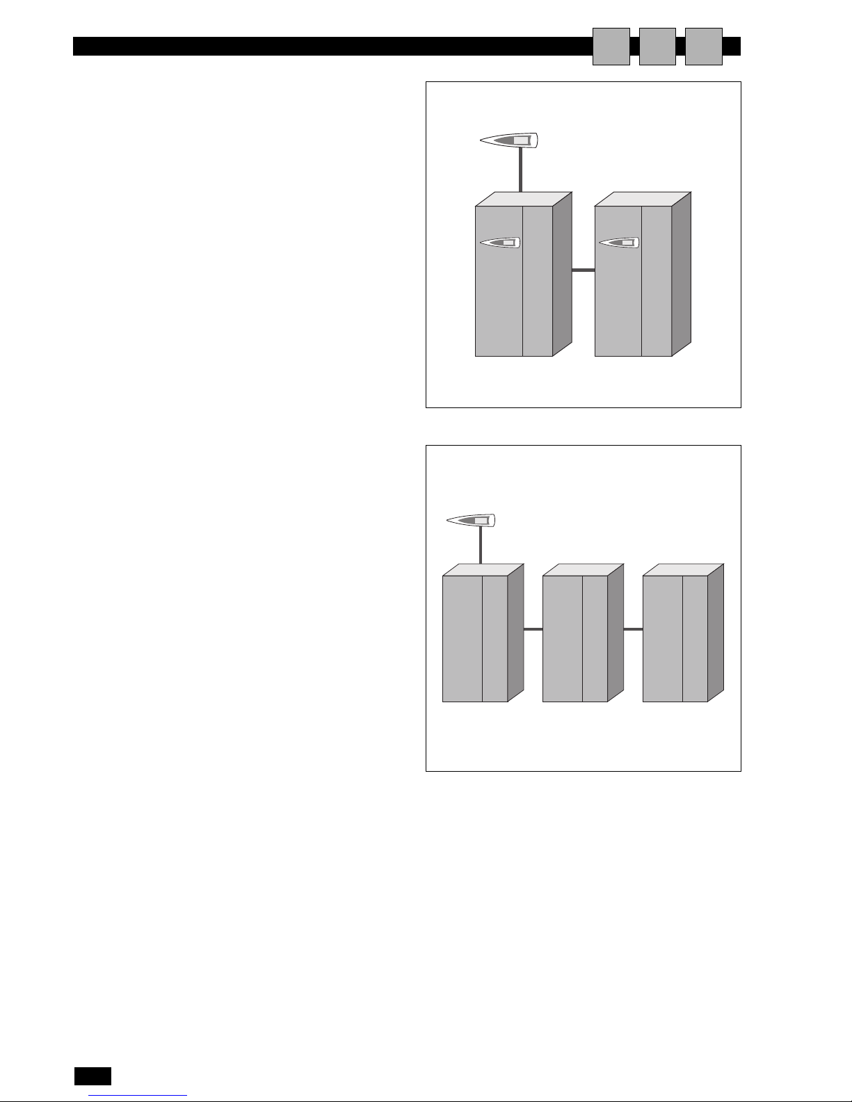
1 Up to 10 units connected in the network with just one
remote share terminal
In this configuration, a power failure on the first unit will cause
the terminal to shutdown, and therefore the information corresponding to the units in the network can no longer be read.
Nonetheless, the other units in the network would continue to
operate normally.
2 Up to 10 units, each with its own terminal
3 Up to 10 units, each with own terminal, with just one
shared remote terminal
Page 18
16
English
TERMINAL EVOLUTION
ELECTRICAL CONNECTIONS
AIU
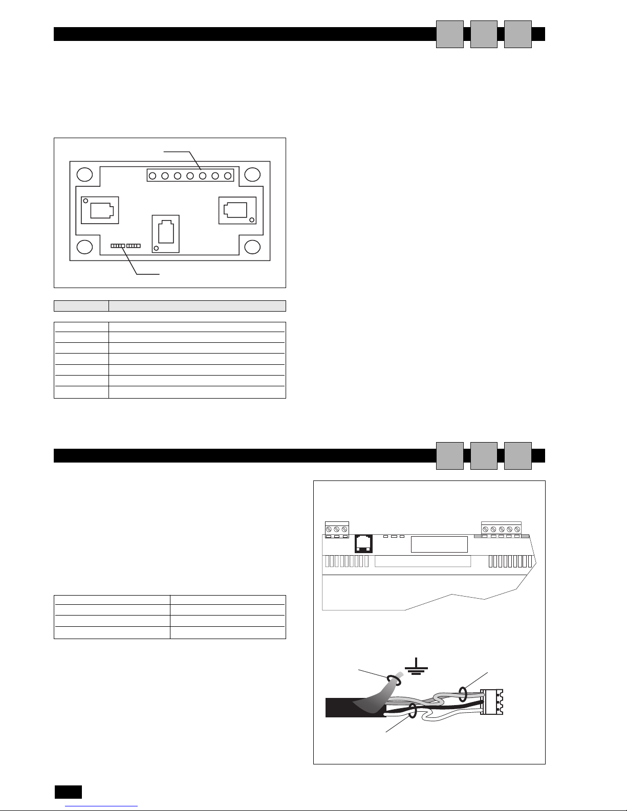
CONNECTION BETWEEN PC01 BOARDS
AIU
The electrical connections must be completed when the units are
off and disconnected from the power supply.
The network can have different configurations, according to the
maximum distance of the connections between the boards and
the remote terminal; for the connections between the remote
terminal and the main board, a 'T' shunt may be required, as
shown in the drawing.
If both the jumpers are installed between 2 and 3 the flow of current is interrupted between the connectors separated by the
dashed line.
If power is required on all the connectors,both the jumpers must
be installed between 1 and 2.
Terminal 0 is an auxiliary terminal and can be used to earth the
shield of the cable; the 'T' shunt must in any case be connected to
a metallic part of the unit that is already earthed.
MAXIMUM DISTANCE BETWEEN THE TERMINAL
AND THE BOARD
1 For local terminals the connection to the main board is already
made using a 3-pair cable and 6-pin telephone connector. The
length of this cable generally does not exceed 3 metres.
2 The remote terminals can be connected to the main board
using the type of telephone cable described in point 1, with a
maximum distance of 50 metres.
3 For greater distances,up to a maximum of 200 metres, a shield-
ed cable must be used (six lead cable with shield and twisted
pairs, AWG24, resistance < 80 ohm/M). The cable may have 3
or 2 pairs, depending on whether the power needs to be supplied to the terminals. The cable is not supplied by CLIMAVENETA HOME SYSTEM s.r.l.
AWG 24 cables with two twisted pairs plus shield, such as the
Belden 8723 or 8102, and AWG 24 cables with three twisted
pairs plus shield, Belden 8103 or similar, are recommended.
Te r minals
pin strips
A
123 123
B
C
terminal function
0 Earth (shield)
1 +VRL ≈ 30Vcc
2 Gnd
3 Rx/Tx4 Rx/Tx+
5 Gnd
6 +VRL ≈ 30Vcc
In this configuration, the local terminal is already connected to
the main board using a telephone cable.
To complete the network wiring, the control boards should be
connected in parallel using a shielded cable and with terminal J11
as the reference, as shown in the figure.
IMPORTANT: the polarity of the network must be observed:
The RX/TX+ on one board must be connected to the RX/TX+
on the other boards; the same is true for RX/TX-.
J11
RX/TX-
RX/TX+
GND
RX/TXRX/TX+
GND
first twisted pair
second twisted pair
shield
programming key
clock board
Terminal on the board Cable connections
GND First pair (both wires)
Rx/Tx - Second pair
Rx/Tx + Second pair
Page 19
17
English
TERMINAL EVOLUTION
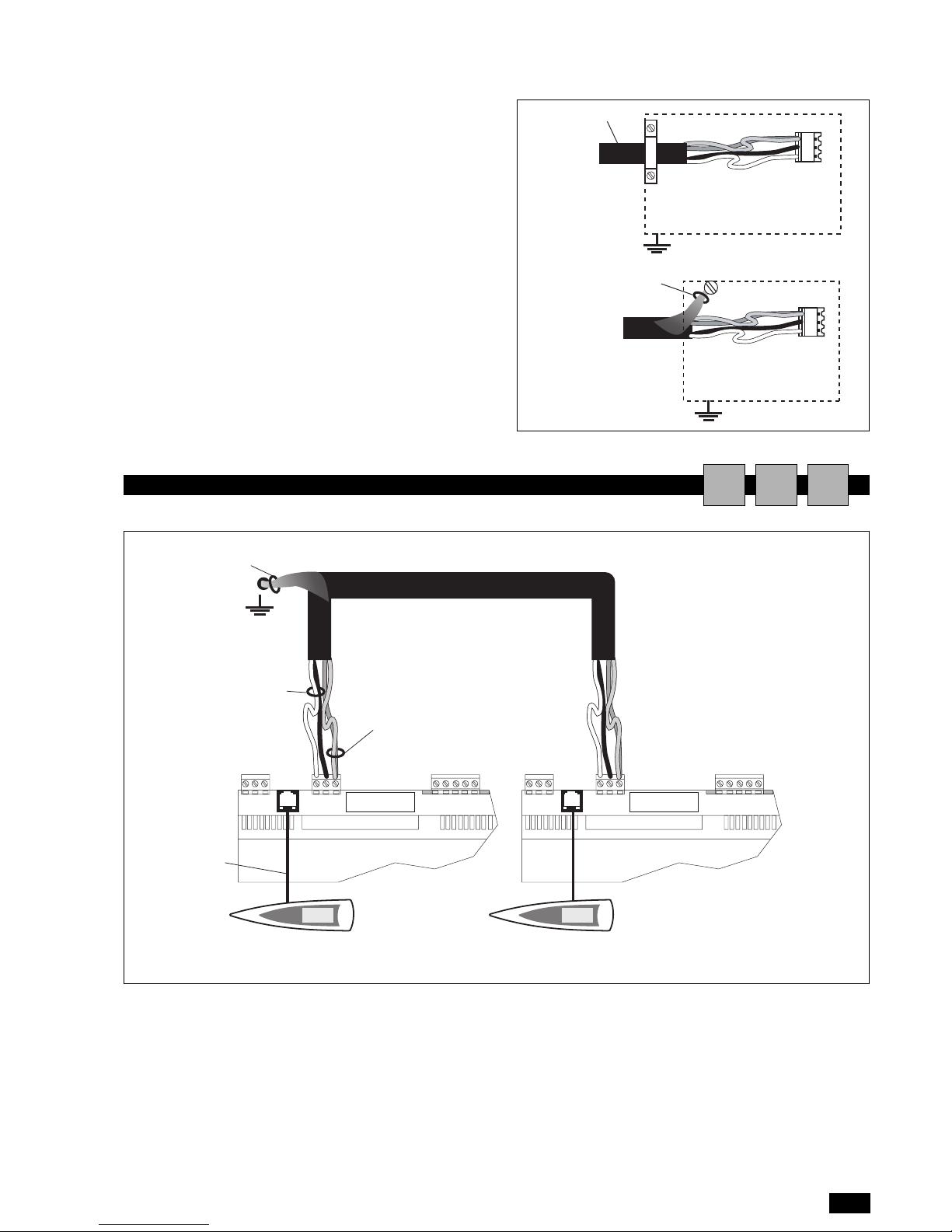
The shield on the shielded cable is earthed at a single point in the
network.
Earthing the cable at different points in the network may cause
control malfunctions.
The connection must be made, where possible, by fastening the
cable with a metal clamp, as shown in the figure on the left.
Alternatively, use the twisted end of the shield, as long as the
length of the earthed shield is a short as possible and a locking
washer is used (figure on the right).
The following pages shows the diagrams for a series of boards
connected to the network, powered by the transformers
installed in the electrical panel for each unit.
J11
J11
shield
shielded cable
LAN CONNECTION BETWEEN 2 OR MORE UNITS
AIU
J11
RX/TX-
RX/TX+
GND
J11
RX/TX-
RX/TX+
GND
First twisted
pair
Board n° 1 Board n° 2
terminal n° 11 terminal n° 12
Second twisted
pair
Cable connected to the earth
on the unit
Telephone cable
max 50 mt
programming
key
Page 20
18
English
TERMINAL EVOLUTION
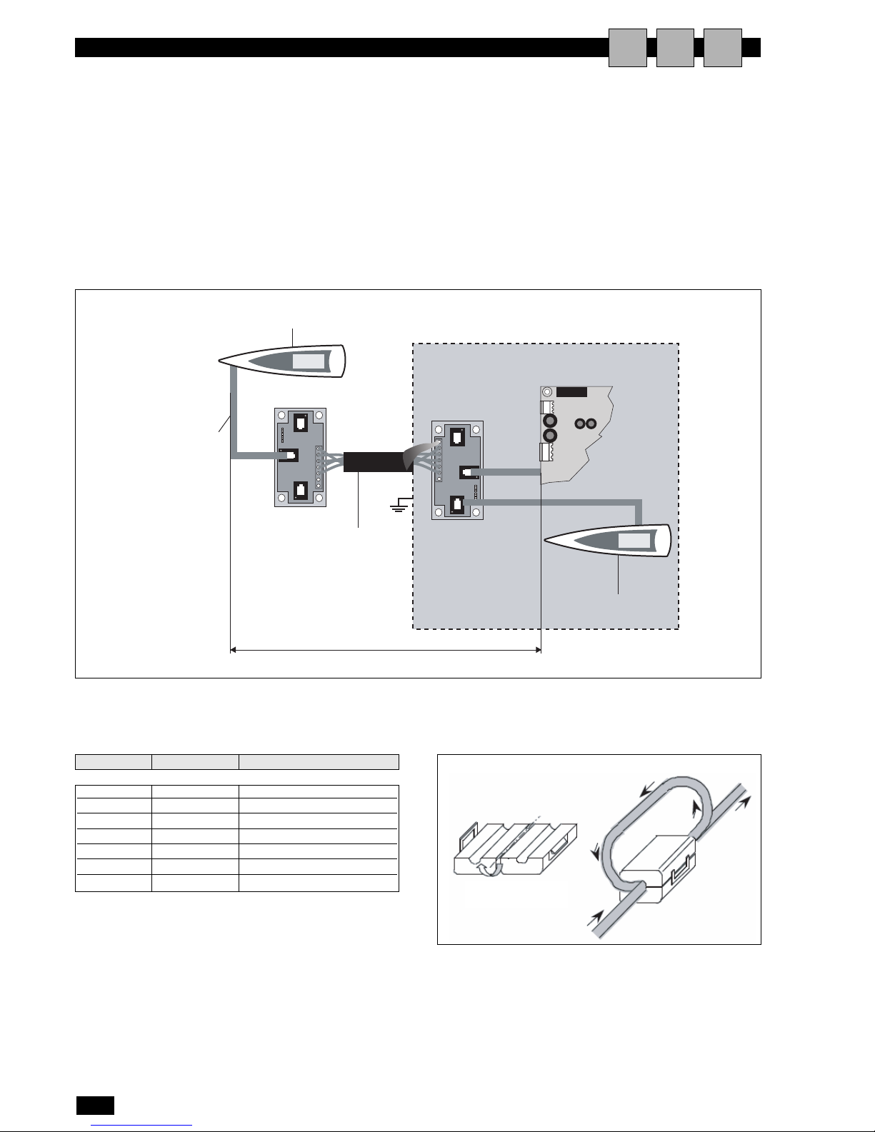
CONNECTION TO THE REMOTE TERMINAL FROM THE BOARD
AIU
EXAMPLE OF CONNECTION TO THE REMOTE TERMINAL POWERED BY THE BOARD
This configuration requires:
1 the use of two 'T' shunts: one fitted on the unit and one near
the remote terminal;
2 the use of the 3x2 shielded cable, so that the power to the
remote terminal is also supplied by the board on unit 1, connected using the 'T' shunt;
3 near the terminal, insert the ferrite to reduce any electromag-
netic disturbance.
J17
J11
Remote terminal no. 32
Term. no. 11
Board no. 1
Three-pair cable
pairs with 6-pin
telephone connector.
Three-pair shielded cable: 3 x 2 x
AWG 24 (six lead cable with
shield and twisted pairs,AWG24,
resistance < 80ohm/M). Remote
terminal no. 32 Board no. 1 Term.
Maximum distance between terminal/board: 200 m
FERRITE
terminal function cable connections
0 Earth shield
1 + VRL ≈ 30Vcc
2 Gnd First pair
3 Rx/Tx - Second pair
4 Rx/Tx + Second pair
5 Gnd First pair
6 + VRL ≈ 30Vcc
Connections for the 2 x 2 x AWG 24 CABLE
(for connecting the remote terminal: without transferring
the power supply)
Page 21
19
English
TERMINAL EVOLUTION
CONFIGURATION OF THE TERMINAL AND THE BOARD
AIU
SETTING THE LOCAL NETWORK ADDRESS ON THE
EVOLUTION TERMINAL AND THE pCO1 BOARD
Before setting the addresses, first check the LAN connection
between the boards, the connection to the remote or shared terminal, and the power supply connections to the unit.
The terminal address can be set only after having connected it to
the power supply using the RJ11 telephone connector.
To enter configuration mode, press the UP ENTER DOWN buttons together (featured on all versions) for at least 5 seconds; the
screen shown in Fig. 1 will be displayed, with the cursor flashing in
the top left corner:
• To set the address of the terminal (display address setting), press
the ENTER button once: the cursor will move to the address
field (nn).
• Use the UP and DOWN buttons to select the desired value,
and confirm by pressing ENTER again.
If the value selected is different from the one saved previously,
the screen shown in Fig. 2 will be displayed and the new value
will be saved to the permanent memory on the display.
If the field nn is set to 0, the terminal will communicate with the
pCO1 board using the “point-to-point” protocol (not pLAN), and
the field XX will not be displayed,as it no longer has meaning.
fig. 1
fig. 2
pCO1: assigning the list of private and shared terminals
Subsequently, to modify the list of terminals associated with each
individual pCO1 board, proceed as follows:
• enter configuration mode by pressing UP ENTER DOWN, as
described in the previous paragraph;
• press the ENTER button until the cursor reaches the field XX
(I/O board address) Fig. 1;
• use the UP and DOWN buttons to select the address of the
desired pCO1 board. The values available correspond to the
pC01 boards that are effectively on line. If the pLAN network is
not working correctly, or no pCO1 board is available, the field
cannot be modified and will show “-”;
• pressing the button once again displays the sequence of screens
shown in Fig. 3;
• again the ENTER button moves the cursor from one field to
the next, and the UP and DOWN buttons change the value of
the current field.
The field P:xx shows the address of the selected board; in the
example in Fig. 3, P12 has been selected.
To exit the configuration procedure and save the data, select the
field “OK ?”, set Yes and confirm by pressing ENTER.
The fields in the “Adr” column represent the addresses of the
terminals associated with the pCO1 board with address 12, while
the Priv/Shared column indicates the type of terminal.
Important: the EVOLUTION terminals cannot be configured as
“Sp” (shared printer), as they have no printer output.
If the terminal remains inactive (no button is pressed) for more
than 30 seconds, it automatically exits the configuration procedure without saving any changes.
Assigning the List of Private and Shared Terminals
fig. 3
LAN ADDRESS OF THE pCO1 BOARD
The address of the boards is set as described below:
1 Disconnect the power supply from the board UPC1m;
2 Remove the J11 connector (Rx/Tx-, Rx/Tx+, GND);
3 Connect the board on unit no. 1 to a user terminal with
address = 0;
4 Power-up the board and at the same time hold the ALARM
and UP buttons until the following screen is displayed:
and then
5 Press the ENTER button to accept the address of the board proposed
on the display, or alternatively the UP and DOWN buttons to modify
the value: set "pLAN address: 1" on unit no.1.
(NOTE: if no button is pressed for 15 seconds, the screen disappears,
and the procedure needs to be repeated from point 1.).
6 Confirm by pressing ENTER;
7 Disconnect the power supply;
8 Repeat the procedure from point 1 to point 4 for unit no. 2. and set
"pLAN address: 2 ";
9 Replace the J11 connectors (Rx/Tx-, Rx/Tx+, GND) on the boards.
10 Repeat the procedure from point 1 to point 4 for the other units.
Display address
setting.........:nn
I/O Board address:xx
Display address changed
Terminal Config
Press ENTER to continue
P12: Adr Priv/Shared
Trm1 02 Sh
Trm2 03 Ph
Trm3 None --OK?NO
SELF TESTING
PLEASE WAIT
pLAN address: 1
up: increase
down: decrease
ENTER: save & exit
pLAN address: 2
up: increase
down: decrease
ENTER: save & exit
Page 22
20
English
TERMINAL EVOLUTION
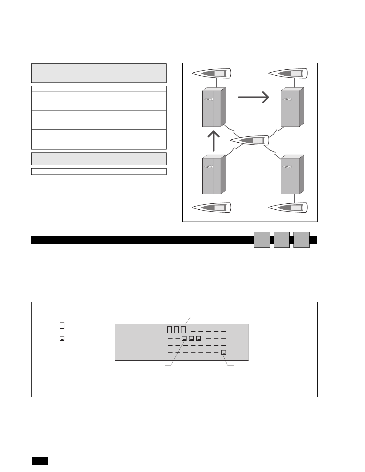
TABLE OF TERMINAL ADDRESSES AND LAN BOARD
ADDRESSES
Fig. 1 represents a network made up of 4 units, each with its own
local user terminal and with a shared remote user terminal (32)
that displays the information for unit 1.
To move from one unit to the next, in sequence
(1>2>3>4>no….. ), simply press ESC + DOWN.
Terminal address
(displayed automatically)
LAN Board Address
(set using the buttons on
the terminal)
11 1
12 2
13 3
14 4
15 5
16 6
17 7
18 8
19 9
20 10
Terminal address
(displayed automatically)
LAN Board Address
(displayed automatically)
32 (remote)-
Board
no. 2
Board
no. 1
Board
no. 3
Board
no. 4
shared user terminal
no.32
DISPLAYING THE NETWORK FROM THE TERMINAL
AIU
From any terminal in the network, holding the UP + ENTER +
DOWN buttons for at least 10 seconds, will display the <<
NetSTAT >> screen ( see Fig. 2).
The NetSTAT screen shows all the LAN boards and all the terminals connected in the network, including the shared remote terminal, with the corresponding addresses.
In the example, the network is made up of 3 LAN boards with
addresses 1, 2, 3, and 4 user terminals with addresses 11, 12, 13
and 32.
1
9
17
25
NetSTAT
T:11
Enter
To Exit
8
16
24
32
board
terminal
board with address 3
terminal with address 11 terminal with address 32
fig. 2
fig. 2
Page 23
21
English
TERMINAL EVOLUTION
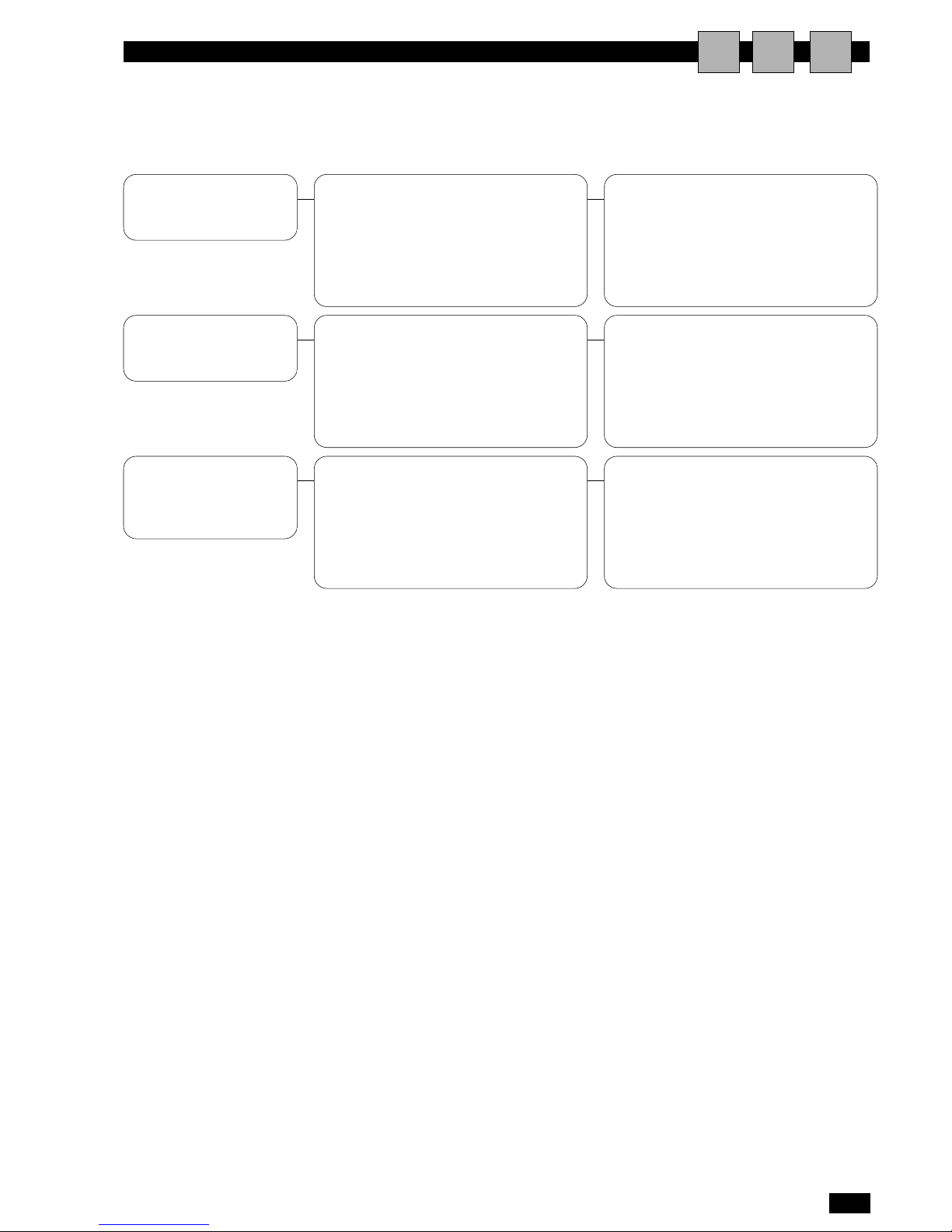
TROUBLESHOOTING
AIU
The connection cable between the pCO1
board and the user terminal may be detached
or broken.
Possible power failure to the pCO1 board.
Possible blown fuse on the pCO1 board or in
the power supply line.
Check the connection between the user
terminal and the pCO1 board.
Check that the pCO1 board is powered and
on, check any fuses in the power supply line.
PROBLEM CAUSE SOLUTION
The user terminal does
not switch on or does
not communicate with
the unit.
The address of the pCO1 board or the user
terminal may be incorrect.
The contrast of the display may have been
adjusted by mistake
Check that the LAN address of the pCO1
board and the address of the user terminal are
compatible.
Check by pressing the PGR+ALARM+UP
buttons to increase or PGR+ALARM+DOWN
to decrease the contrast.
The user terminal is on
but no icons or menu
items are displayed.
The address of the terminal may be incorrect.
The connection cable between the units may
be detached or broken.
The connection cable may be detached or
broken.
Check the LAN connection between the units.
Check the connection on the three-way 'T'
shunt.
The shared user terminal cannot communicate
with the unit or the units
connected in the
network (LAN).
If after having checked all the possible causes of the problems described here the problem has not been resolved, contact your nearest service centre for further information on how to proceed and resolve the problem.
Page 24

Dé Longhi Group - Via L. Seitz, 47 - 31100 Treviso (Italia)
COD.5787000900
 Loading...