

Page 1

TECHNICAL MANUAL
CVM 2
C 5001 CV/04-99 GB
Summary
1 CONNECTIONS ..............................................................................................................................4
1.1 TEMPERATURE PROBES.............................................................................................................4
1.2 PRESSURE PROBES.......................................................................................................................5
1.3 L IVE DIGITAL INPUTS................................................................................................................6
1.4 RELAY OUTPUTS .......................................................................................................................6
1.5 SERIAL CONNECTIONS ..............................................................................................................7
1.6 KEYBOARD...................................................................................................................................7
1.7 REMOTE KEYBOARD .................................................................................................................. 7
1.8 POWER SUPPLY ........................................................................................................................... 8
2 SETUP................................................................................................................................................8
2.1 ACCESS TO PROGRAMMING.......................................................................................................8
3 SOFTWARE.....................................................................................................................................9
3.1 DESCRIPTION OF USER INTERFACE .........................................................................................9
3.2 UNIT STARTUP ............................................................................................................................ 9
3.3 UNIT SHUTDOWN ..................................................................................................................... 10
3.4 ALARMS...................................................................................................................................10
3.4.1 Circuit and/or compressor alarms..............................................................................10
3.4.2 General alarms...............................................................................................................10
4 ALARM SIGNALS ........................................................................................................................11
5 HOW TO VISUALISE THE RESOURCE STATUS .................................................................13
5.1 V ISUALISATION OF UNIT'S RESOURCE STATUS....................................................................13
6 REGULATION................................................................................................................................15
6.1 CHILLED WATER REGULAT ION ............................................................................................. 15
6.2 HOT WATER REGULATION.....................................................................................................15
7 PARAMETER LIST.......................................................................................................................16
8 ENCLOSURES ...............................................................................................................................23
1
Page 2
TECHNICAL MANUAL
CVM 2
C 5001 CV/01-99 IT
Board description
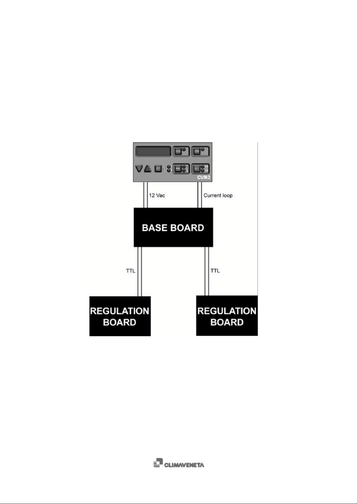
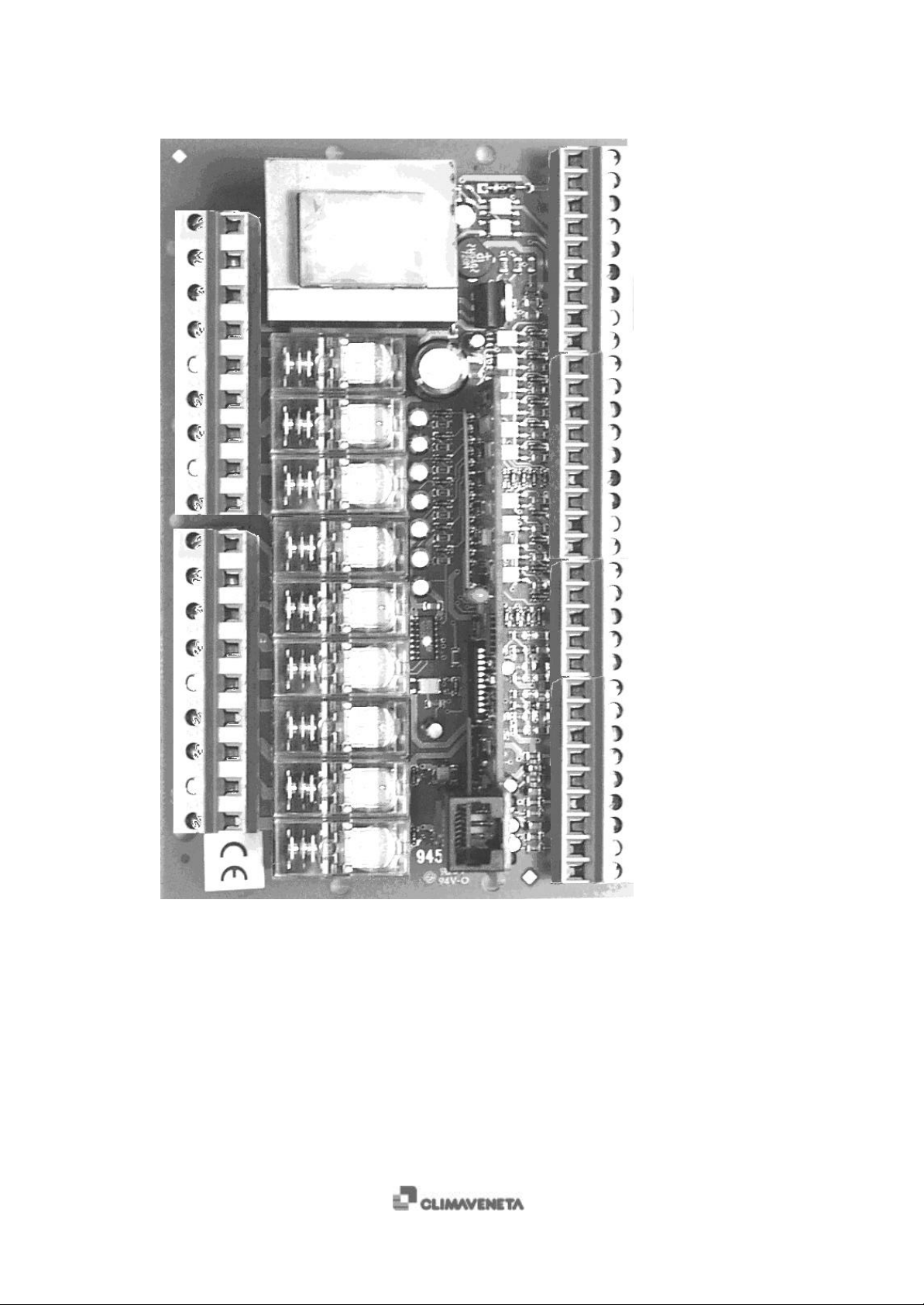
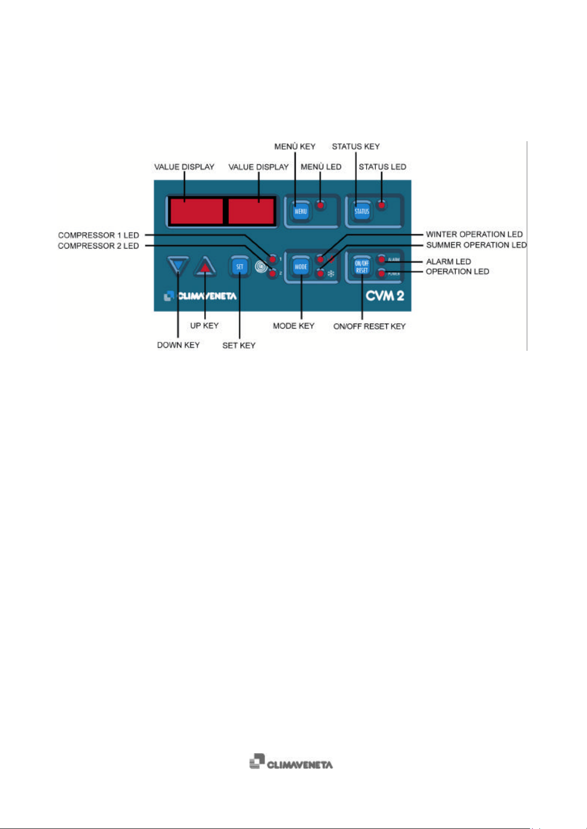
The system consists of a main board which is located inside the electrical panel, and of a keyboard
(Enclosures fig. 1). The boards for the continuous adjustment of the fan speed are connected to the
main board. The keyboard communicates with the main board through a serial current-loop and
receive the power supply from the main board.
Figure 1-0 COMPLETE SYSTEM
2
Page 3
50
49
48
47
46
45
44
43
42
41
40
39
38
37
36
35
34
33
Figure 1-1 MAIN BOARD
TECHNICAL MANUAL
CVM 2
C 5001 CV/04-99 GB
32
31
30
29
28
27
26
25
24
23
22
21
20
19
18
17
16
15
14
13
12
11
10
9
8
7
6
5
4
3
2
1
3
Page 4
TECHNICAL MANUAL
CVM 2
C 5001 CV/01-99 IT
1 Connections
1.1 Temperature probes
The connected temperature probes are 3, or 4 in the case of water-water heat pumps with reversing cycle on the water side.
TERMINALS MEANING
1, 2 Inlet water temperature
3, 4 1st evaporator outlet water temperature
5, 6 2nd evaporator outlet water temperature (only with plate
heat exchangers)
7, 8 (only for water-water heat pumps
Condenser inlet water temperature
with reversing cycle on the water side)
Temperature [°C] -55 -50 -40 -30 -20
Resistance [Ω]
485 510 562 617 677
Temperature [°C] -10 0 10 20 25
Resistance [Ω]
740 807 877 951 990
Temperature [°C] 30 40 50 60 70
Resistance [Ω]
1029 1111 1196 1286 1378
Temperature [°C] 80 90 100 110 120
Resistance [Ω]
1475 1575 1679 1796 1896
Temperature probes verification procedure:
• disconnect the power supply to the unit;
• disconnect the probe from microprocessor’s terminals;
• use a digital Ohmmeter to measure the resistance value of the probe;
• measure the temperature near the probe cap;
• compare the resistance value measured with the one shown in the table: the corresponding temperature must be
approximately the same as the measured one.
4
Page 5
TECHNICAL MANUAL
CVM 2
C 5001 CV/04-99 GB
1.2 Pressure probes
There are two 4-20mA , 0-30 bar pressure probes for all the units, except for the water-water heat pumps with reversing cycle
on the water side.
TERMINALS MEANING
7, 8 1st circuit condensing pressure
9, 10 2nd circuit condensing pressure
Pressure [Bar] 0.0 0.5 1.0 1.5 2.0 2.5 3.0 3.5
Current [mA] 4.00 4.27 4.54 4.80 5.07 5.34 5.61 5.87
Pressure [Bar] 4.0 4.5 5.0 5.5 6.0 6.5 7.0 7.5
Current [mA] 6.14 6.41 6.68 6.94 7.21 7.48 7.75 8.01
Pressure [Bar] 8.0 8.5 9.0 9.5 10.0 10.5 11.0 11.5
Current [mA] 8.28 8.55 8.82 9.08 9.35 9.62 9.89 10.15
Pressure [Bar] 12.0 12.5 13.0 13.5 14.0 14.5 15.0 15.5
Current [mA] 11.43 10.69 10.96 11.23 11.49 11.76 12.03 12.30
Pressure [Bar] 16.0 16.5 17.0 17.5 18.0 18.5 19.0 19.5
Current [mA] 12.56 12.83 13.10 13.37 13.63 13.90 14.17 14.44
Pressure [Bar] 20.0 20.5 21.0 21.5 22.0 22.5 23.0 23.5
Current [mA] 14.70 14.97 15.24 15.51 15.77 16.04 16.31 16.58
Pressure [Bar] 24.0 24.5 25.0 25.5 26.0 26.5 27.0 27.5
Current [mA] 16.84 17.11 17.38 17.65 17.92 18.18 18.45 18.72
Pressure transducer verification procedure:
• switch off the compressors and leave the unit with only the “ON/OFF switch” button ON;
• disconnect the cable from terminal 7 or 9 of microprocessor, depending on the probe;
• place digital milliammeter between the disconnected terminal and the cable and read the current value;
• read the pressure value using a gauge placed near the transducer;
• compare the readings with the values shown in the table.
5
Page 6
TECHNICAL MANUAL
CVM 2
1.3 Live digital inputs
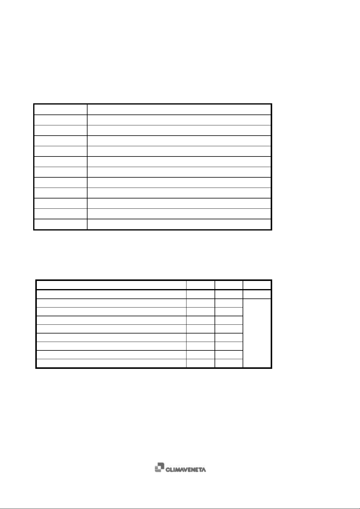
The following table shows the logic meaning of the AT digital inputs (230 Vac) and their arrangement:
TERMINALS MEANING
11, 12, 17 Common to all high voltage inputs
22 - AT1 Circuit 1 high pressure switch
16 - AT2 Circuit 2 high pressure switch
23 - AT3 Circuit 1 low pressure switch
15 – AT4 Circuit 2 low pressure switch
18 – AT5 Circuit 1 compressor thermal protection
14 – AT6 Circuit 2 compressor thermal protection
19 – AT7 Circuit 1 fans thermal protection
13 – AT8 Circuit 2 fans thermal protection
C 5001 CV/01-99 IT
20 – AT9 Water differential pressure switch and external flow switch
21 – AT10 ON/OFF switch
1.4 Relay outputs
RELAY N.O. N.C. COM.
RL1 Cumulative alarm 41 39 40
RL2 Antifreeze 44
RL3 circuit 1 fan control 35 34
RL4 circuit 1 compressor control 43
RL5 circuit 2 compressor control 36 37
RL6 circuit 2 fan control 33
RL8 circuit 1 4-way valve control 46 47 45
RL9 circuit 2 4-way valve control 38
RL10 water pump control 42
6
Page 7
TECHNICAL MANUAL
LOCAL
REMOTE
CVM 2
C 5001 CV/04-99 GB
1.5 Serial connections
8-pin, TTL telephone -type connector.
1.6 Keyboard
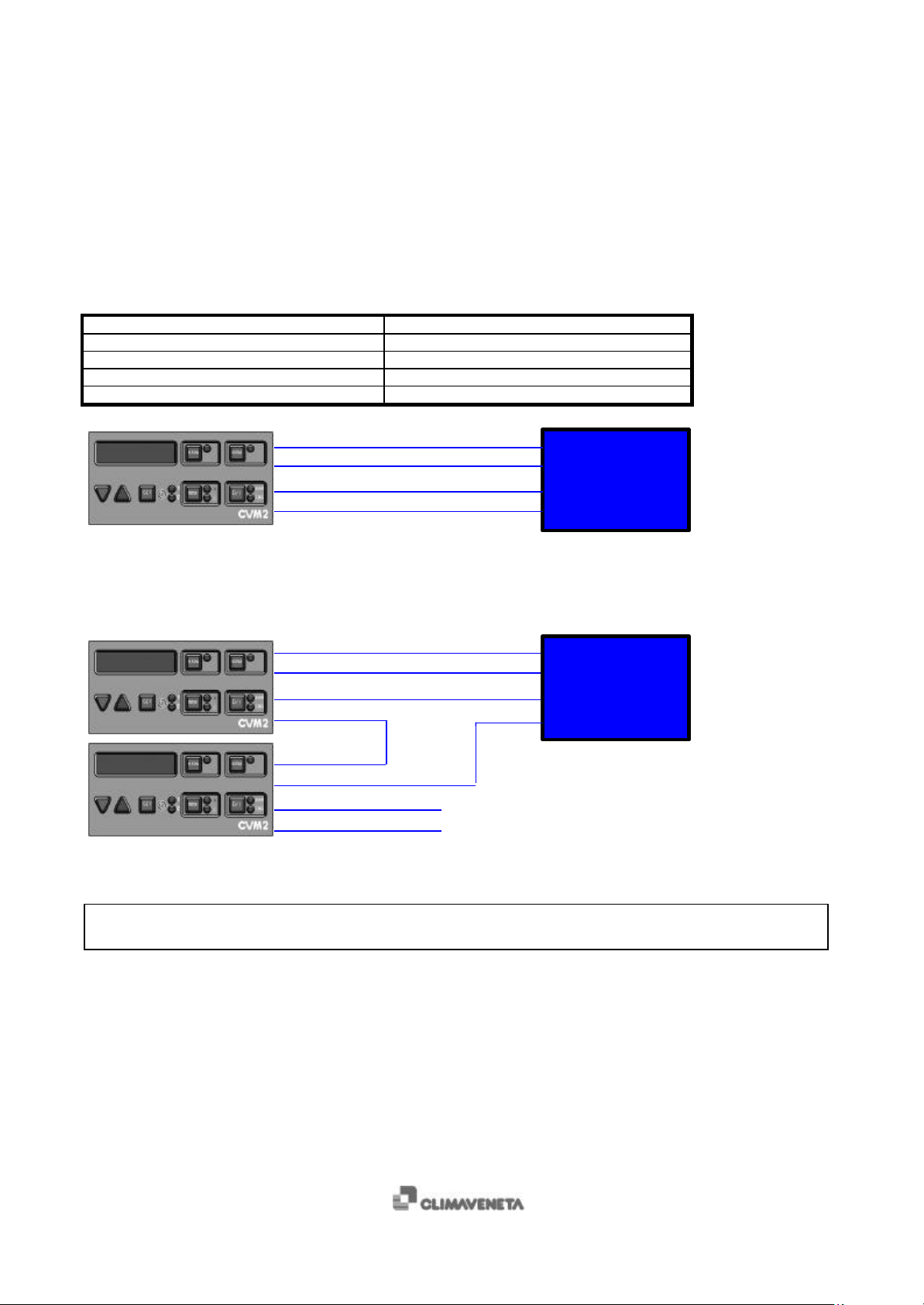
It is connected to the following terminals, as indicated in the figure below:
KEYBOARD TERMINALS MAIN BOARD TERMINALS
4 28
3 29
1 31
2 32
1 12Vac 31
2 12Vac 32
3 Current loop è 29
4 ç Current loop 28
Figure 1-1 KEYBOARD CONNECTION
BASE CVM 2
1.7 Remote keyboard
1 12Vac 31
2 12Vac 32
3 Loop è 29
4 28
BASE CVM 2
3
4 ç Loop
1 12Vac (from supplementary
2 12Vac (from supplementary
Figure 1-2 REMOTE KEYBOARD CONNECTION
NB: The supplementary transformer is the 230/12 Vac transformer supplied with the remote keyboard kit.
The maximum length of the remote keyboard’s AWG24-type serial cable is 50 metres.
7
Page 8

TECHNICAL MANUAL
CVM 2
1.8 Power supply
The CVM 2 has a 230 Vac supply to terminals 49 and 50, phase and neutral respectively.
C 5001 CV/01-99 IT
2 Setup
2.1 Access to programming
Press the MENU key;
$ The corresponding LED will light up and two fixed values will be displayed.
+ Press the SET key;
$ The parameter index (on the right-hand side of the display) will start flashing.
+ Scroll through the parameter list using the “arrow up” and “arrow down” keys to visualise the required parameter.
+ Press the SET key
$ the value of the parameter (on the left-hand side of the display) will start flashing.
+ Modify the value using the “arrow up” and “arrow down” keys.
+ Press the SET key to confirm the operation.
+ To access the FACTORY menu scroll through the list until parameter 92 appears, then enter the password.
+ To exit, press the MENU key.
WARNING
To memorise the modifications and make them active you must turn off the power supply (using the main switch)
and, after a few seconds, turn it back on.
8
Page 9

TECHNICAL MANUAL
CVM 2
C 5001 CV/04-99 GB
3 Software
3.1 Description of user interface
If the POWER LED is on, it means that the electronic control is supplied with power.
3.2 Unit startup
+ Press the ON/OFF/RESET key.
$ The inlet temperature value will be displayed on the screen.
+ Press the MODE key.
• If the unit is a CHILLER:
$ The COOLING LED comes on. The two COMPRESSOR 1 and COMPRESSOR 2 LED’s start flashing,
indicating the selection and stand-by condition required by the timer. Then they become steady, indicating operational
readiness, first of COMPRESSOR 1 and then of COMPRESSOR 2.
• If the unit is a HEAT PUMP:
$ the HEATING LED comes on. The two COMPRESSOR 1 and COMPRESSOR 2 LED’s start flashing,
indicating the selection and stand-by condition required by the timer. Then they become steady, indicating operational
readiness, first of COMPRESSOR 1 and then of COMPRESSOR 2.
To modify the operating mode, press the MODE key; the unit will prepare for the change by shutting down the compressors
and then reactivating them in accordance with the procedure described above.
9
Page 10

TECHNICAL MANUAL
CVM 2
3.3 Unit shutdow n
C 5001 CV/01-99 IT
+ Press the ON/OFF/RESET key.
$ The display will go off.
3.4 ALARMS
There are two types of alarms: circuit/compressor and general alarms.
3.4.1 Circuit and/or compressor alarms
Visualisation of the circuit and compressor alarms.
The circuit and/or compressor alarms are visualised with the corresponding flashing code on the DISPLAY while the
ALARM LED comes on. The related compressor is simultaneously shut down.
Alarm reset:
+ Press the ON/OFF/RESET key: the unit will be shut down.
3.4.2 General alarms
Visualisation of the general alarms
The general alarms are visualised with the corresponding flashing code on the DISPLAY while the ALARM LED comes on.
The compressors are simultaneously shut down.
Alarm reset:
+ Press the ON/OFF/RESET key: the unit will be shut down.
10
Page 11
TECHNICAL MANUAL
CVM 2
C 5001 CV/04-99 GB
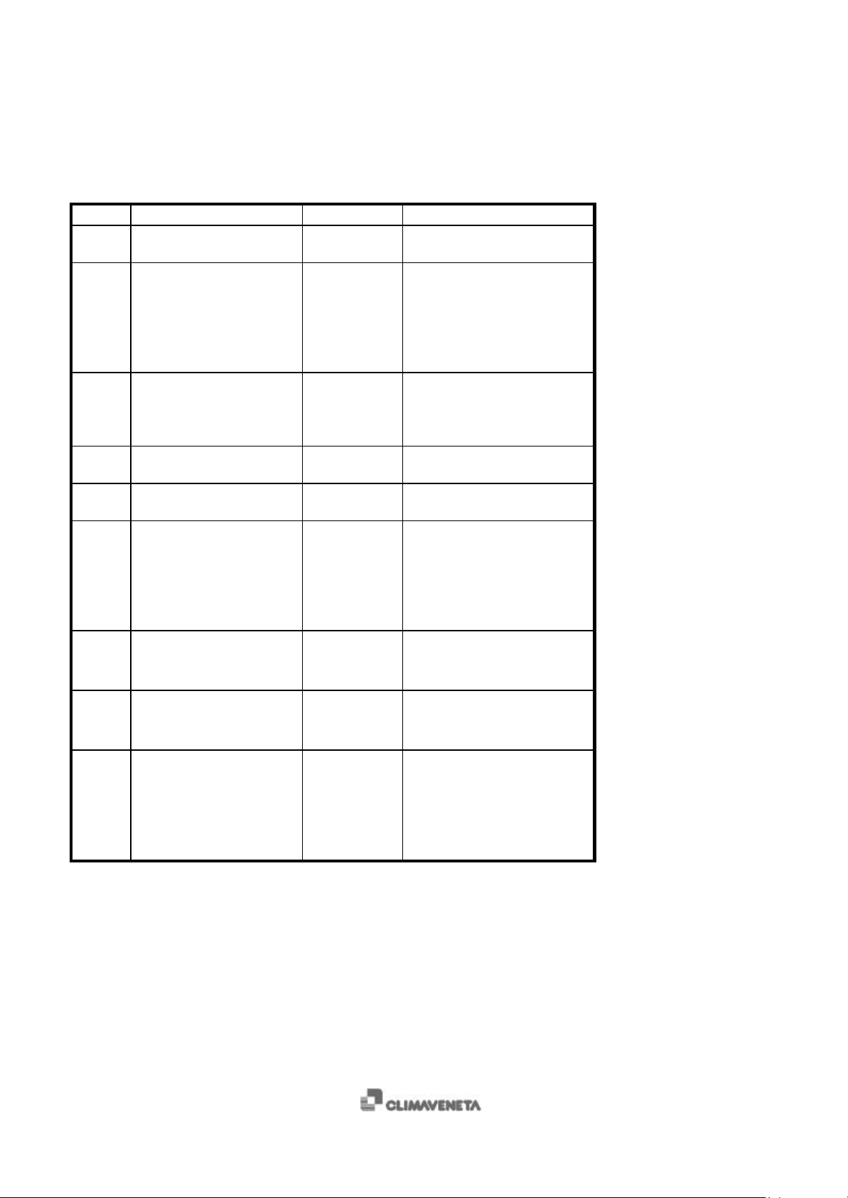
4 Alarm signals
Code ALARM Reset type Cause
E00 Remote off Automatic
E01 Circuit 1 high pressure Manual
E02 Circuit 1 low pressure Automatic
E03 Compressor 1 thermal
protection
E04 Circuit 1 fan thermal
protection
E05 Circuit 1 antifreeze Manual
E06 ST2 probe malfunction Automatic
E07 ST5 probe malfunction Automatic
E21 Circuit 2 high pressure Manual
Manual
Manual
% Check the connection between
terminals 8 and 9.
% Check the power supply to the
fans;
% Check if the condensing coils
are clean (Chiller);
% Check the water flow rate to
the evaporator (Heat pump).
% Check the flow rate to the
evaporator (Chiller);
% Check if the condensing coils
are clean (Heat pump).
% Possible compressor motor
malfunction
% Possible electric fan motor
malfunction
% Check the water flow rate to
the evaporator;
% Check the operation of the
water pump;
% Verify if cold set point is
correct (parameters: 2, 58, 59).
% Check the connections to
board terminals 3 and 4;
% Probe malfunction.
% Check the connections to
board terminals 7 and 8;
% Probe malfunction.
% Check the power supply to the
fans;
% Check if the condensing coils
are clean (Chiller);
% Check the water flow rate to
the evaporator (Heat pump).
11
Page 12

E22 Circuit 2 low pressure Automatic
E23 Compressor 2 thermal protection Manual
E24 Circuit 2 fan thermal protection Manual
E25 Circuit 2 antifreeze Manual
E26 ST3 probe malfunction Automatic
E27 ST6 probe malfunction Automatic
E40 ST1probe malfunction Automatic
E41 Water differential pressure
switch (external flow switch)
Automatic
TECHNICAL MANUAL
CVM 2
C 5001 CV/01-99 IT
% Check the water flow rate to
the evaporator (Chiller)
% Check if the condensing coils
are clean (Heat pump).
% Possible compressor motor
malfunction.
% Possible electric fan motor
malfunction.
% Check the water flow rate to
the evaporator;
% Check the operation of the
water pump;
% Verify if cold set point is
correct (parameters: 2, 58, 59).
% Check the connections to
board terminals 5 and 6;
% Probe malfunction.
% Check the connections to
board terminals 9 and 10;
% Probe malfunction.
% Check the connections to
board terminals 1 and 2;
% Probe malfunction.
% Check the water flow rate to
the evaporator;
% Purge the air from the water
side;
% Possible pressure switch
malfunction.
12
Page 13
TECHNICAL MANUAL
CVM 2
C 5001 CV/04-99 GB
5 How to visualise the resource status
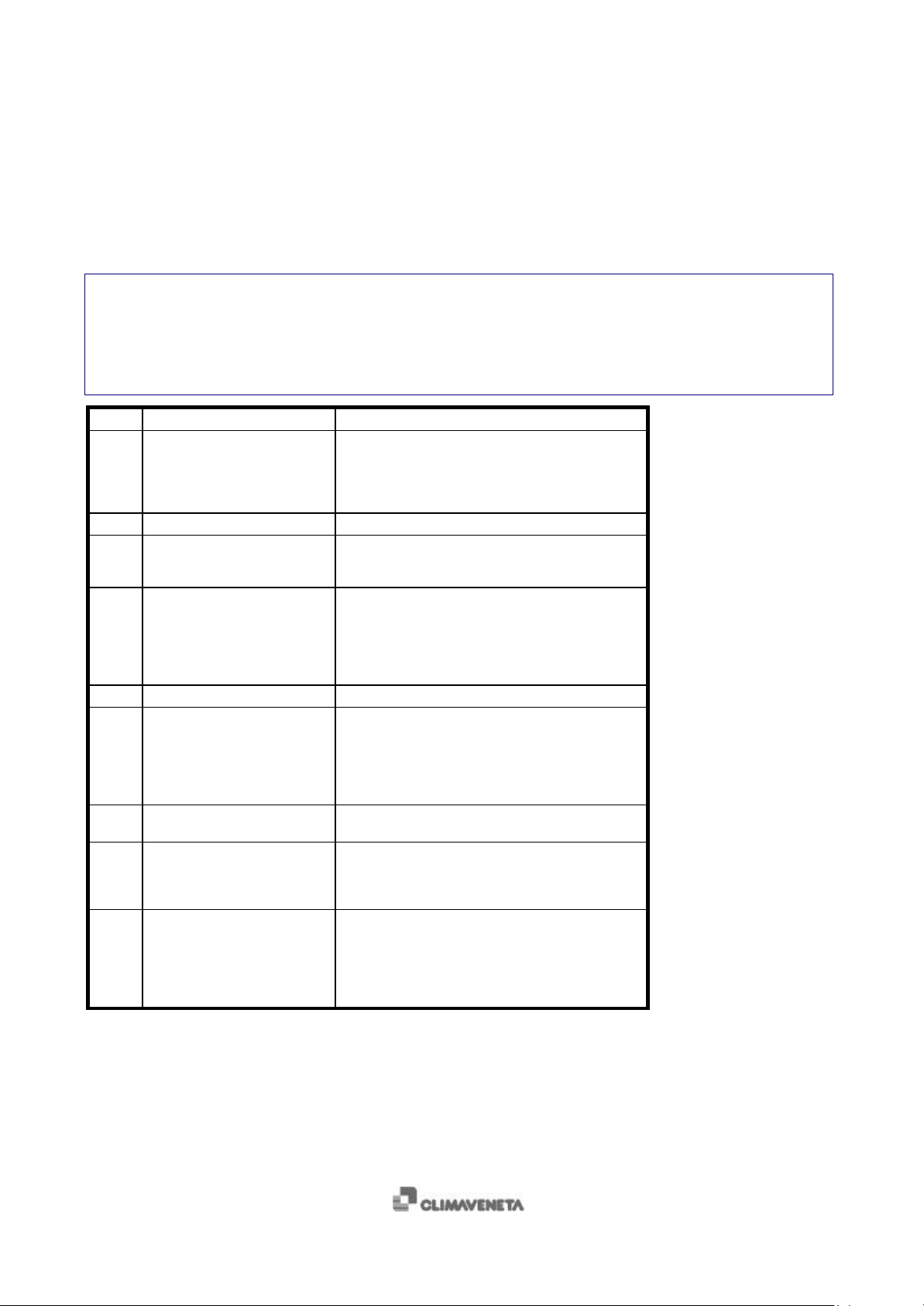
5.1 Visualisation of the unit’s resource status
+ Press the STATUS key.
$ The STATUS LED comes on. The resource index appears on the left-hand side of the DISPLAY, while the
corresponding status appears on the right-hand side.
+ Press the “arrow up” and/or “arrow down” key to scroll through the list.
Index Resource Meaning
01 Compressor 1 01 summer cycle operation
02 Compressor 1 hours Operating hours since last operating hours reset
03 Circuit 1 fans 01 operating
04 Circuit 1 defrosting -- not present
05 Fan module outlet 1 0 - 100%
21 Compressor 2 -- not present
22 Compressor 2 hours -- not present
23 Circuit 2 fans -- not present
24 Circuit 2 defrosting -- not present
02 winter cycle operation
03 defrost operation
04 delay on compressor start
06 compressor off
02 off for defrosting
06 fans off
01 defrosting
02 compressor 1 safety count
03 defrosting time count
04 active defrosting delays
06 inactive
01 summer cycle operation
02 winter cycle operation
03 defrost operation
04 delay on compressor start
06 compressor off
Compressor operating hours since last time reset
01 operating
02 off for defrosting
06 fans off
01 in progress
02 compressor 1 safety count
03 defrosting time count
04 active defrosting delays
06 inactive
13
Page 14
TECHNICAL MANUAL
C 5001 CV/01-99 IT
25 Fan module outlet 2 --- not present
0 - 100%
40 ST1 inlet water temperature --- probe not present
value in °C/10
ERR probe error
41 Remote ON/OFF status --- not present
ON contact closed
OFF contact open
42 Outlet temperature of 1st ST2
evaporator
--- probe not present
value in °C/10
ERR probe error
43 Outlet temperature of 2nd ST3
evaporator
--- probe not present
value in °C/10
ERR probe error
44 Condensing water inlet
temperature reading for unit
with reversing cycle on water
--- probe not present
value in °C/10
ERR probe error
side
ST5 or condensing pressure
reading for unit with fans speed
regulation SP5
45 Condensing pressure reading for
unit with fans speed regulation
SP5
--- probe not present
value in °C/10
ERR probe error
46 Water pump status --- pump not present
01 pump on
06 pump off
47 Water pump hours --- pump not present
Number of hours counted since the last time reset
48 Antifreeze heater --- heater not present
01 heater on
06 heater off
CVM 2
14
Page 15
TECHNICAL MANUAL
CVM 2
C 5001 CV/04-99 GB
6 Reg ulation
6.1 Chilled water regulation
+ To modify the working set point of the unit in Chiller mode, modify the value of parameter 2, following the
parameter access procedure described above (chap. 2).
N° of parameters Default value
2 Chiller set point 12 °C
4 Chiller differential 1 °C
48 ∆t
NB: regulation is made based on the temperature reading at the evaporator inlet.
2 °C
6.2 Hot water regulation
To modify the working set point of the unit in Heat Pump mode, modify the value of parameter 3, following the parameter
access procedure described above (chap. 2).
N° of parameters Default value
3 Heat pump Set Point 40 °C
5 Heat pump differential 1 °C
48 ∆t
NB: regulation is made based on the temperature reading at the condenser inlet.
2 °C
15
Page 16
TECHNICAL MANUAL
CVM 2
C 5001 CV/01-99 IT
7 Parameter list
= USER PARAMETERS
M = UNIT PARAMETERS
CI = CIRCUIT PARAMETERS
CO = COMPRESSOR PARAMETERS
N. TYPE UNIT PARAMETERS RANGE DEFAUL
1 M TYPE OF UNIT
0↔5
Value Description
0 Water-air chiller
1 Water-water chiller
3 Water-air heat pump
5 Water-water heat pump with reversing cycle on liquid side
Table 7-1 UNIT TYPE’
T
Tab. 7-1
2 M COLD SET POINT (COOLING)
3 M WARM SET POINT (HEATING)
4 M COOLING DIFFERENTIAL
5 M HEATING DIFFERENTIAL
COMPRESSORS
2°
∆t p.48
1°
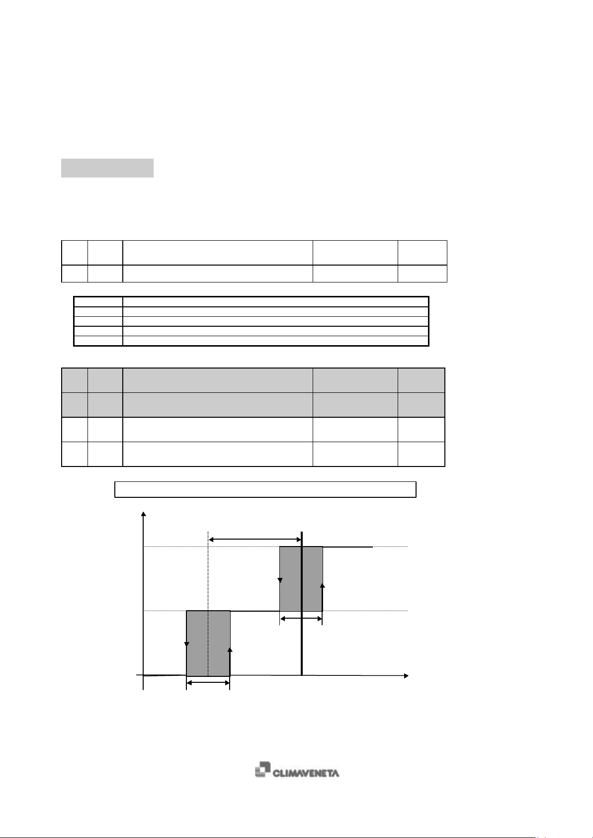
Figure 7-1 REGULATION IN CHILLER MODE
DIFFERENTIAL p.4
CHILLER OPERATION
SUMMER SET
p.2
p.58↔p.59
p.60↔p.61
0↔126
0↔126
DIFFERENTIAL p.4
TEMPERATURE
120
°C/10
400
°C/10
10
°C/10
10
°C/10
16
Page 17
TECHNICAL MANUAL
CVM 2
C 5001 CV/04-99 GB
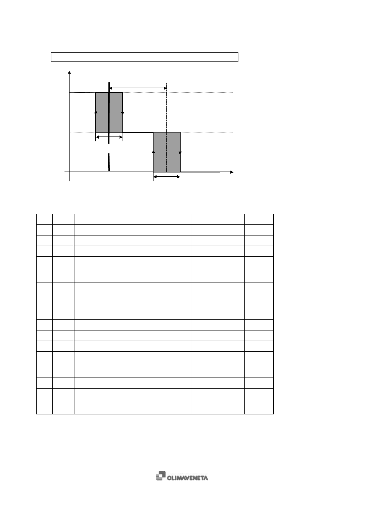
HEAT PUMP OPERATION
COMPRESSORS
∆t p.48
2°
1°
DIFFERENTIAL p.5
Figure 7-2 HEAT PUMP REGULATION
6 M SUMMER FAN SPEED MINIMUM PRESSURE
7 M SUMMER FAN SPEED MAXIMUM PRESSURE
8 M WINTER FAN SPEED MINIMUM PRESSURE
9 M WINTER FAN SPEED MAXIMUM PRESSURE
10 M CIRCUIT No. 1 FAN OPERATING MODE 0=MODULATING
11 M CIRCUIT No. 2 FAN OPERATING MODE 0= MODULATING
12 M MODULATING OUTPUT LOWER LIMIT
13 M MODULATING OUTPUT UPPER LIMIT
14 M SUMMER CUT-OFF SET POINT
15 M WINTER CUT-OFF SET POINT
16 M RESTART AT 100%: 0=W/OUT
17 M CUT-OFF BY-PASS TIME
18 M FAN PEAK CURRENT TIME
19 M FAN START MODE 0=ON REQUEST
WINTER SET
p.3
DIFFERENTIAL p.5
TEMPERATURE
0↔30
0↔30
0↔30
0↔30
OUTPUT
1=ON/OFF
2=DISABLED
OUTPUT
1=ON/OFF
2=DISABLED
0↔100
0↔100
0↔30
0↔30
CURRENT PEAK
1=WITH CURRENT
PEAK
0↔126
0↔126
1=CONTINUOUS
14 Bar
19 Bar
5 Bar
4 Bar
0 num.
0 num.
30 %
100 %
13 Bar
6 Bar
1 flag
30 sec
30 sec
1 flag
17
Page 18
TECHNICAL MANUAL
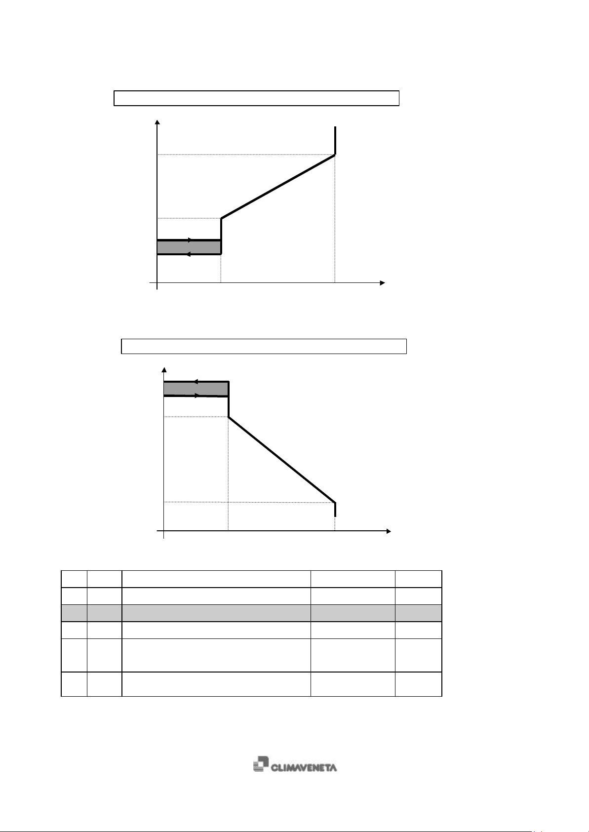
MINIMUM p.6
CVM 2
C 5001 CV/01-99 IT
CHILLER OPERATING MODE VENTILATION
PRESSURE [Bar]
MAXIMUM p.7
CUT-OFF + DELTA
CUT-OFF p.14
Figure 7-3 FANS SPEED REGULATION IN CHILLER MODE
MINIMUM p.12 MAXIMUM p.13
HEAT PUMP OPERATING MODE VENTILATION
CUT-OFF - DELTA
CUT-OFF p.15
MINIMUM p.8
PRESSURE [Bar]
MAXIMUM p.9
Figure 7-4 FANS SPEED REGULATION IN HEAT PUMP MODE
MINIMUM p.12 MAXIMUM p.13
FAN SPEED
FAN SPEED
20 M DEFROST START PRESSURE
21 M DEFROST END PRESSURE
22 M DEFROST STAND-BY TIME
23 M MAXIMUM DEFROST TIME
24 M DELAY BETWEEN FIRST CIRCUIT END OF
DEFROST AND SECOND CIRCUIT START
DEFROST
25 M FORCED VENTILATION PRESSURE DURING
DEFROST
18
0↔30
0↔30
0↔126
0↔126
0↔126
0↔30
30 Bar
140 Bar
30 min
5 min
2 min
16 Bar
Page 19
TECHNICAL MANUAL
CVM 2
C 5001 CV/04-99 GB
26 M ANTIFREEZE ALARM SET
27 M ANTIFREEZE HYSTERESIS
p.62↔p.63
0↔126
28 M ANTIFREEZE RESET TYPE 0=AUTOMATIC
1=MANUAL
29 M ANTIFREEZE ALARM BY-PASS CONFIGURATION
(E05/E25) FOR CIRCUIT 1 AND 2
0=NEVER
1=HEAT
2=COOL
3=ALWAYS
31 M ANTIFREEZE BY-PASS TIME
32 M ANTIFREEZE HEATER START SET POINT
33 M ANTIFREEZE HEATER START HYSTERESIS
0↔255
-280↔500
0↔126
38 M FAN MOTORS PHASE ANGLE VALUE
0↔126
39 M WATER PUMP OPERATING MODE 0=NOT PRESENT
1=CONTINUOUS
2=ON REQUEST BY
THERMOREGULATOR
40 M COMPRESSOR START DELAY AFTER PUMP
START
41 M PUMP SHUTDOWN DELAY AFTER
COMPRESSOR SHUTDOWN
42 M DIFFERENTIAL PRESSURE SWITCH AND
EXTERNAL FLOW SWITCH ALARM BY-PASS
0↔126
0↔126
0↔126
(E41) UPON PUMP START
43 M DIFFERENTIAL PRESSURE SWITCH AND
EXTERNAL FLOW SWITCH ALARM RESET BY-
0↔126
PASS (E41)
44 CO TYPE OF RESET OF COMPRESSOR THERMAL
PROTECTION ALARM (E03/E23)
45 CI TYPE OF RESET OF FAN THERMAL
PROTECTION ALARM (E04/E24)
46 CO COMPRESSOR THERMAL PROTECTION ALARM
BY-PASS TIME (E03/E23)
0=AUTOMATIC
1=MANUAL
0=AUTOMATIC
1=MANUAL
0↔126
47 M TEMPERATURE UNIT OF MEASUREMENT 0=CELSIUS
1=FAHRENHEIT
48 M
∆t 0↔126
49 M SAFETY TIME BETWEEN COMPRESSOR START
AND SHUTDOWN
50 M SAFETY TIME BETWEEN 1st AND 2nd
COMPRESSOR START
0↔126
0↔126
30
°C/10
40
°C/10
1 flag
1 num.
30 sec
30
°C/10
40
°C/10
5 num.
1 num.
60 sec
60 sec
30 sec
10 sec
1 flag
1 flag
1 sec
0 flag
20
°C/10
6 sec
x10
36 sec
x10
19
Page 20
TECHNICAL MANUAL
C 5001 CV/01-99 IT
51 CI LOW PRESSURE BY-PASS TIME IN HEAT PUMP
MODE FOR CIRCUITS 1 AND 2
52 CI LOW PRESSURE BY-PASS TIME IN CHILLER
MODE FOR CIRCUITS 1 AND 2
53 M DELAY BETWEEN 1st AND 2nd COMPRESSOR
START
54 M DELAY BETWEEN 1st AND 2nd COMPRESSOR
SHUTDOWN
55 M COMPRESSORS AVAILABLE ON SET POINT
56 CI CIRCUIT 1 CONFIGURATION
57 CI CIRCUIT 2 CONFIGURATION
Parameter value Meaning
0 NO COMPRESSOR
1 1 COMPRESSOR
2 NOT USED
Table 7-2 CIRCUIT CONFIGURATION
CVM 2
0↔255
0↔255
0↔126
0↔126
0↔2
0↔2
0↔2
120 sec
120 sec
10 sec
5 sec
2 num.
Tab. 7-2
Tab. 7-2
58 M SUMMER SET POINT LOWER LIMIT (CHILLER)
59 M SUMMER SET POINT UPPER LIMIT (CHILLER)
60 M WINTER SET POINT LOWER LIMIT (HEAT
PUMP)
61 M WINTER SET POINT UPPER LIMIT (HEAT PUMP)
-20↔p.2
p.2↔50
-10↔p.3
p.3↔60
62 M LOWER ANTIFREEZE SET POINT LIMIT
63 M UPPER ANTIFREEZE SET POINT LIMIT
-28↔p.26
p.26↔60
64 CI 4-WAY VALVE 0=ABSENT (p.1=0-1)
1=PRESENT (p.1=3,
5)
65 CI 4-WAY VALVE POLARITY 0=RELAY ON IN
CHILLER MODE
1=RELAY ON IN
HEAT PUMP MODE
66 M DEFROST 0=SEPARATE
1=SIMULTANEOUS
67 M MODE KEY CONFIGURATION 0=COOL/STAND-
BY 1=MULTIPLE
(HEAT/COOL/STBY)
68 M OPERATING MODE FROM REMOTE ON
(MAINTAINS THE PREVIOUS STATUS UPON
SHUTDOWN FROM REMOTE UNIT)
0=CHILLER
1=PUMP 2=STANDBY
10 °C
20 °C
30 °C
50 °C
3 °C
10 °C
-- flag
1 flag
-- flag
1 flag
2 num.
20
Page 21
TECHNICAL MANUAL
1=SIMULTANEOUS
C 5001 CV/04-99 GB
70 M DIFFERENTIAL/FLOW SWITCH ALARM DELAY
71 M UNIT ADDRESS
72 M ST1 PROBE CONFIGURATION
73 M ST2 PROBE CONFIGURATION
74 M ST3 PROBE CONFIGURATION
76 M SP5 PROBE CONFIGURATION
77 M SP6 PROBE CONFIGURATION
Parameter value Meaning
0 NOT PRESENT
1 DIGITAL INPUT ON/OFF
2 ANALOGIC INPUT
Table 7-3 PROBE CONFIGURATION
CVM 2
0↔126
0↔255
0↔2
0↔2
0↔2
0↔2
0↔2
2 sec
0 flag
Tab. 7-3
Tab. 7-3
Tab. 7-3
Tab. 7-3
Tab. 7-3
78 M ST1 PROBE OFFSET
79 M ST2 PROBE OFFSET
80 M ST3 PROBE OFFSET
82 M SP5 PROBE OFFSET
83 M SP6 PROBE OFFSET
-100↔100
-100↔100
-100↔100
-100↔100
-100↔100
84 CI DEFROST CYCLES 0=NOT ENABLED
1=ENABLED
85 CI ANTIFREEZE HEATER 0=ABSENT
1=PRESENT
86 CI OPERATION OF ANTIFREEZE HEATERS
0↔2
Parameter value Meaning
0 OPERATION WITH THERMOREGULATOR
1 OPERATION WITH THERMOREGULATOR AND IN DEFROST MODE
2 OPERATION WITH THERMOREGULATOR AND IF REQUIRED BY 2nd
WATER CIRCUIT (ONLY FOR WATER-WATER UNITS WITH REVERSING
CYCLE ON GAS SIDE)
Table 7-4 OPERATION OF ANTIFREEZE RESISTANCES
87 CI HIGH PRESSURE ALARM RESET (E01/E21) 0=AUTOMATIC
1=MANUAL
88 CI LOW PRESSURE ALARM RESET (E02/E22) 0=AUTOMATIC
1=MANUAL
89 CI FAN OPERATING MODE 0=INDIPENDENT
(IF CONDENSING
COILS ARE
SEPARATE)
----- °C/10
----- °C/10
----- °C/10
----- Bar/10
----- Bar/10
1 flag
----- flag
Tab. 7-4
1 flag
0 flag
----- flag
(SINGLE
CONDENSING
COIL)
21
Page 22
TECHNICAL MANUAL
CVM 2
90 M REMOTE CONTROL CONFIGURATION
C 5001 CV/01-99 IT
0↔2
Tab. 7-5
Parameter value Meaning
0 ABSENT
1 HEAT PUMP (p.67=1 E p.68=2)
2 PRESENT (ONLY FOR ON/OFF)
Table 7-5 REMOTE CONTROL CONFIGURATION
WARNING
If the unit is switched off using the keyboard’s ON/OFF key, the antifreeze resistance control will also go off.
This protection will remain active if the unit is switched off using a remote ON/OFF control or by switching off the
compressors with the MODE key.
CHILLER (p.67=0 E p.68=2)
92 M PASSWORD num.
93 ---------- --------------------------------------------- ------------------------ --------
22
Page 23
8 Enclosures
TECHNICAL MANUAL
CVM 2
C 5001 CV/04-99 GB
23
 Loading...