

CLIMAVENETA BRA2 0021, BRA2 0031, BRA2 0041, BRA2 0025, BRA2 0061 Installation, User And Maintenance Manual
...Page 1
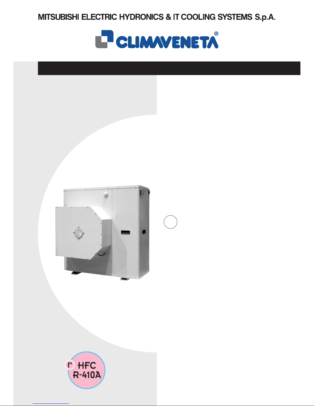
Water chillers and air/water heat
pumps with centrifugal fans
EN
BRA2 0021÷0061
BRN2 0021÷0061
INSTALLATION, USER AND MAINTENANCE MANUAL
Page 2
2
BRA2 - BRN2 EN
INDEX
The manufacturer reserves the right to modify the data in this manual without warning.
ENVIRONMENTAL INFORMATION: This unit contains fluorinated greenhouse gases covered by the Kyoto Protocol.
The maintenance and disposal operations must only be carried out by qualified personnel.
General warnings 3
Waiver of liability 3
Fundamental safety rules 3
Identification 4
Receiving, handling and installing the 4
product
Characteristics 5
Dimensioned drawings 6
Water connections 7
Air ducting 11
Electrical connections 13
Mains power supply connections 14
Installer connections 14
General technical data 16
Operating limits 18
Pressure drop and pressure head available 19
to system
Fan pressure gain curves 21
Checking and starting up the unit 22
Led e displays 23
Displaying alarms 32
Peak limiter alarm signals 33
Operating characteristics 35
Shutting down for long periods 36
Routine maintenance 36
Special maintenance 36
Disposal 36
Troubleshooting 37
Useful information 39
U I A
AAI
I
A
I A
I A
I A
I A
A
A
A
A
I A
I AU
U I A
UIA
I
A
I A
I
I
A
I
A
I
I
A
I A
IU
A
I A
I
A
User
Installer
Assistance
Important
Prohibition
Danger voltage
Danger high temperatures
The following symbols are used in some parts of this publication and inside the unit:
U
I
A
Page 3
3
BRA2 - BRN2 EN
GENERAL WARNINGS
U I A
These appliances have been designed to chill and/or
heat water and must be used in applications compatible
with their performance characteristics; these appliances
are designed for residential or similar applications.
Incorrect installation, regulation and maintenance or
improper use absolve the manufacturer from all liability,
whether contractual or otherwise, for damage to people,
animals or things.
Only those applications specifically indicated in this list
are permitted
Read this manual carefully. All work must be carried
out by qualified personnel in conformity with legislation in
force in the country concerned.
The warranty is void if the above instructions are not
respected and if the unit is started up for the first time without the presence of personnel authorised by the Company
(where specified in the supply contract) who should draw up
a “start-up” report.
The documents supplied with the unit must be consigned
to the owner who should keep them carefully for future consultation in the event of maintenance or service.
When the items are consigned by the carrier, check that the
packaging and the unit are undamaged.
If damage or missing components are noted, indicate this on
the delivery note. A formal complaint should be sent via fax
or registered post to the After Sales Department within eight
days from the date of receipt of the items.
All repair or maintenance work must be carried out by the
Company’s Technical Service or qualified personnel following the instructions in this manual.
Do not modify or tamper with the appliance as this may create situations of danger; in such cases the manufacturer of
the appliance is not liable for any damage caused.
FUNDAMENTAL SAFETY RULES
U I A
WAIVER OF LIABILITY
U I A
When operating equipment involving the use of electricity and water, a number of fundamental safety rules must be observed,
namely:
This publication is the sole property of Climaveneta. Any
reproduction or disclosure of such is strictly prohibited without the written authorisation of Climaveneta.
This document has been prepared with maximum care and
attention paid to the content shown. Nonetheless, Cli-
maveneta waives all liability deriving from the use of such
document.
Read this document carefully.
All work must be performed, components selected and
materials used professionally and in complete accordance
with the legislation in force in material in the country concerned, and considering the operating conditions and
intended uses of the system, by qualified personnel.
The unit must not be used by children or by unfit persons without suitable supervision.
Do not touch the unit with bare feet or with wet or
damp parts of the body.
Never perform any cleaning operations before having
disconnected the unit from the mains power supply.
Do not modify safety or control devices without authorisation and instructions from the manufacturer.
Do not pull, detach or twist the electrical cables coming
from the unit, even when disconnected from the mains
electricity supply.
Do not open doors or panels providing access to the
internal parts of the unit without first ensuring that the
mains switch is in the off position.
Do not introduce pointed objects through the air
intake and outlet grills.
Do not dispose of, abandon or leave within reach of
children packaging materials (cardboard, staples, plastic
bags, etc.) as they may represent a hazard.
Power supply to the unit must be disconnected using a
switch with suitable characteristics, to be supplied and
installed by the installer.
Respect safety distances between the unit and other
equipment or structures. Guarantee adequate space for
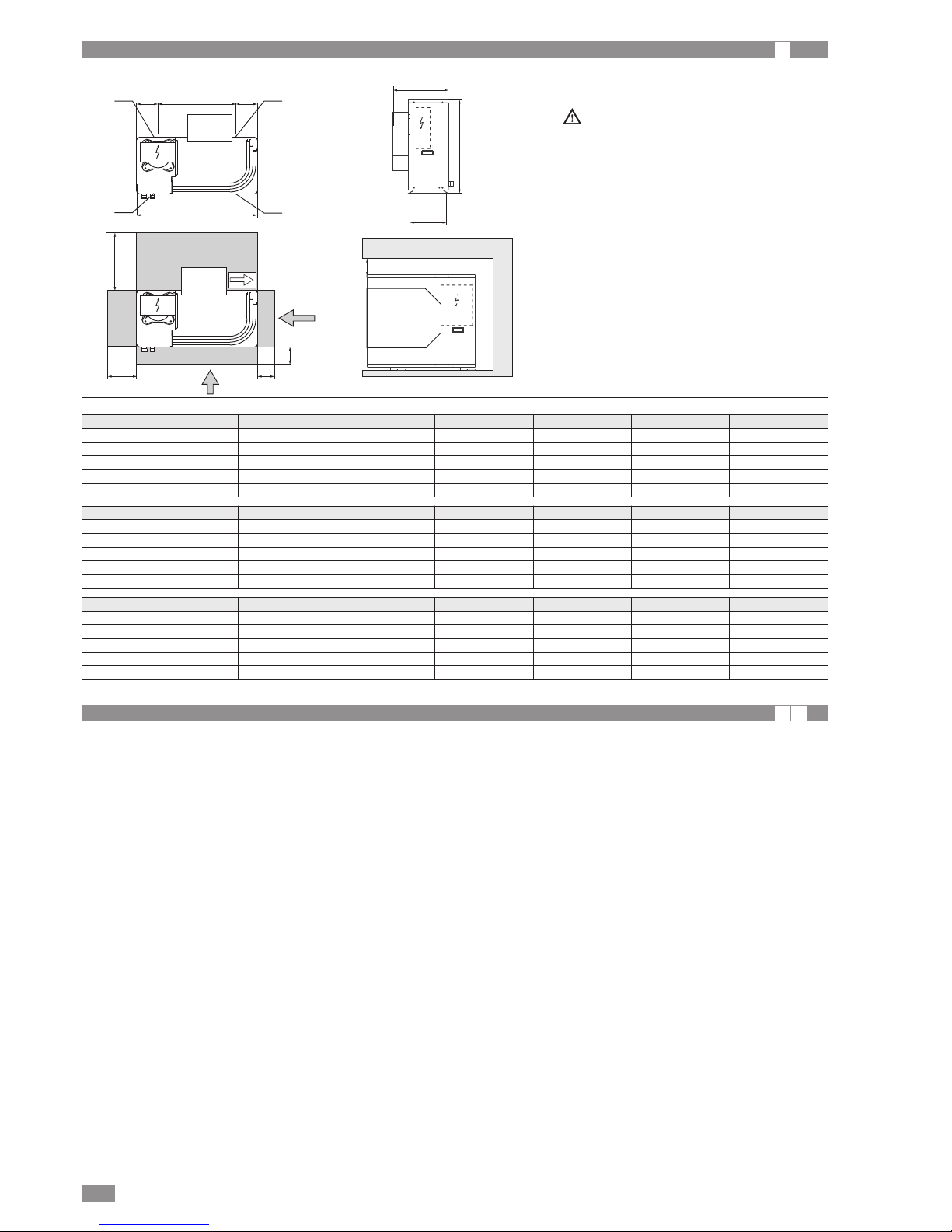
access to the unit for maintenance and/or service operations (see the figure on page 5).
Power supply: the size of the electrical cables must be
adequate for the power of the unit and the power supply
voltage must correspond with the value indicated on the
respective units. All units must be earthed in conformity
with legislation in force in the country concerned.
Some terminals in the electrical panel may be powered even after the unit is disconnected.
Make sure power is not connected before proceeding.
Water connections should be carried out as indicated in
the instructions to guarantee correct operation of the
unit.
Add glycol to the water circuit if the unit is not used during the winter or the circuit is not emptied.
Handle the unit with the utmost care (see weight distribution table) to avoid damage.
Page 4
BRA2 - BRN2 EN
4
MODEL:
VOLTAGE:
CODE:
De' Longhi S.p.a. - 31100 Treviso / Italia
Via L.Seitz, 47 - tel. 04224131 fax 0422413659
COOLING CAPACITY ------------------- kW
HEATING CAPACITY ------------------- kW
REFRIGERANT TYPE ------------------REFRIGERANT CHARGE ------------------- Kg
MAXIMUM PRESSURE ------------------- bar
MAIN ELECTRICAL POWER SUPPLY ------------------- V---Hz
AUXILIARY ELECTRICAL POWER SUPPLY ------------------- V---Hz
MAX. POWER INPUT ------------------- kW
MAX. CURRENT INPUT ------------------- A
START-UP CURRENT ------------------- A
WIRING DIAGRAM ------------------- N°
OPERATING WEIGHT ------------------- Kg
YEAR OF FABRICATION -------------------
IDENTIFICATION
U I A
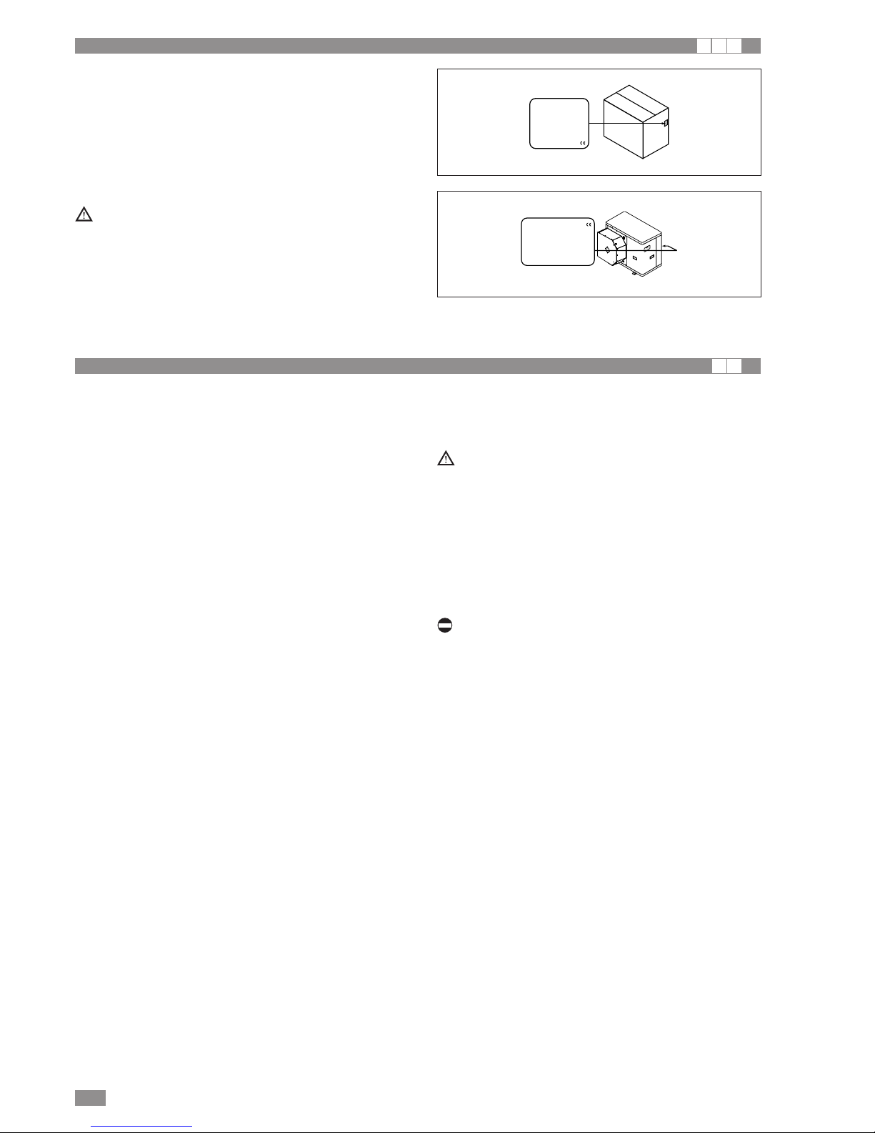
The chiller can be identified by the:
Packaging label
Giving the data identifying the product.
Rating plate
Giving the technical and performance data of the unit.
If this is lost, ask the After Sales Service for a replacement.
Tampering with or the removal or absence of rating
plates or other means enabling the unit to be identified
causes problems during installation and maintenance.
RECEIVING, HANDLING AND INSTALLING THE PRODUCT
I A
The chillers are supplied accompanied by:
- installation, user and maintenance manual;
- CE declaration;
CHOICE OF INSTALLATION SITE
Before installing the unit, agree with the customer the site
where it will be installed, taking the following points into consideration:
• Check that the fixing points are adequate to support the
weight of the unit;
• Pay scrupulous respect to safety distances between the
unit and other equipment or structures to ensure that air
entering the unit and discharged by the fans is free to circulate.
HANDLING AND POSITIONING
The unit should always be handled by qualified personnel
using equipment adequate for the weight of the chiller.
• Before handling the unit, check the capacity of the lift
equipment used, respecting the instructions on the packaging.
• To move the unit horizontally, make appropriate use of a
lift truck or similar, bearing in mind the weight distribution
of the unit.
To lift the unit, insert tubes long enough to allow positioning of the lifting slings and safety pins in the special feet
on the unit.
For the sizes of these tubes, see the figures shown in the
corresponding section.
• To avoid the slings damaging the unit, place protection
between the slings and the unit.
Position the unit in the site indicated by the customer.
Place either a layer of rubber (min. thickness 10 mm) or
vibration damper feet (optional) between the base and
support surface.
Fix the unit, making sure it is level and that there is easy
access to water and electrical components.
If the site is exposed to strong winds, fix the unit adequately using tie rods if necessary.
If a heat pump unit is being installed, make sure the condensate is drained using the drain hose supplied as standard.
Prevent leaves, branches or snow from accumulating
around the unit. These could reduce the efficiency of the
unit.
The installation, user and maintenance manual is an
integral part of the unit and should therefore be read and
kept carefully.
It is recommended that the packaging should not be
removed until the unit is located in the installation site.
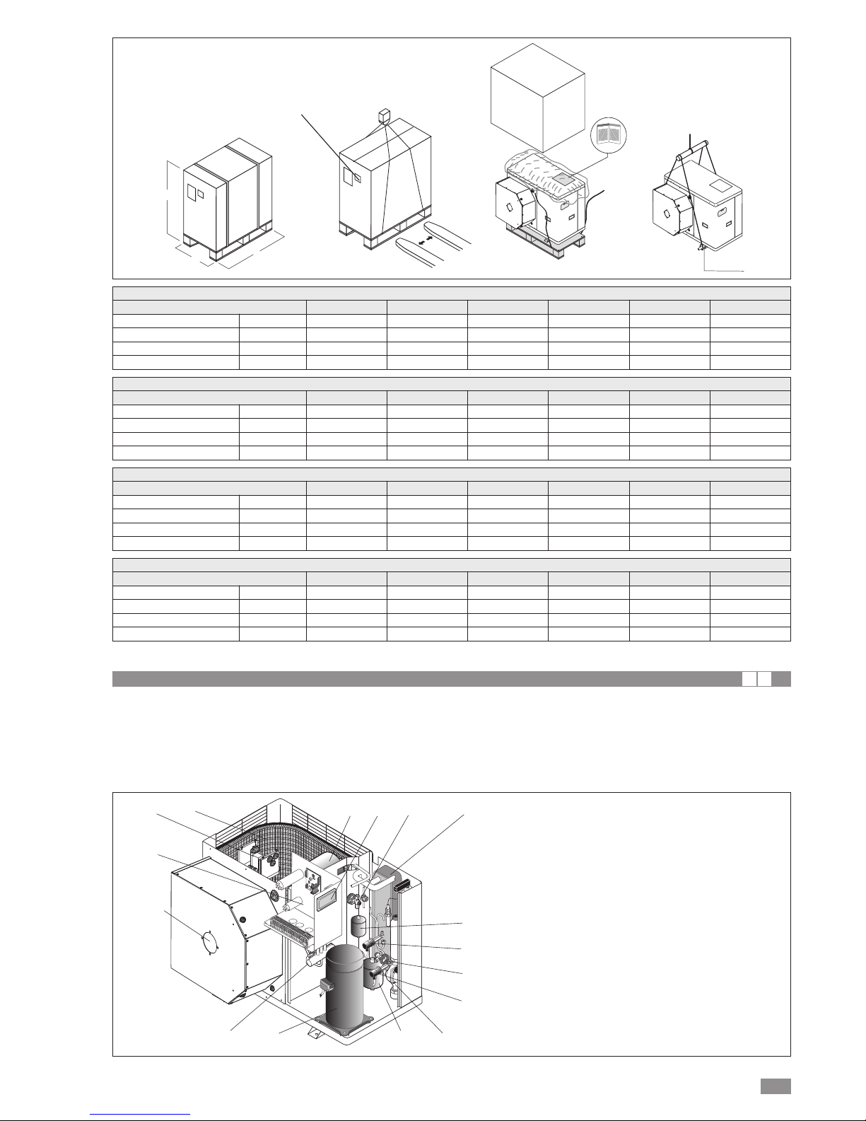
During transport, the chiller should be kept in a vertical position
The weight of the chiller is biased towards the compressor side (side of the packaging with the barcode,
see the figure at the foot of the page).
Do not dispose of packaging materials in the environment or leave them within reach of children as they may
represent a hazard.
Page 5
BRA2 - BRN2 EN
5
CHARACTERISTICS
I A
H
P
L
BAR CODE
Hole Ø22
The BRA2 and BRN2 appliances are air-water units operating on R-410A and refrigerant are suitable for outdoor installation. The units are CE marked, as established by the EU
directives, including the latest amendments, and the corresponding approximated national legislation.
They are factory tested and on site installation is limited to
water and electrical connections.
10
9
5
6
4
3
219
11
7
13
14
8
12
15
1 Electrical panel
2 Control panel
3 Heat exchanger installation side
4 Low pressure switch
5 High pressure switch
6 Scroll compressor
7 Filter
8 Thermostatic valve
9 Centrifugal fan
10 Heat exchanger external side
11 Pump (accessory)
12 Liquid receiver (BRN2 only)
13 Expansion tank
(models WITH HYDRONIC UNIT only)
14 Reversing valve (BRN2 only)
15 Fan board
BRA2 Dimensions and weight with standard packaging
Size
0021M-T 0025M-T 0031M-T 0041M-T 0051T 0061T
Dimension L mm 970 970 970 970 970 970
Dimension P mm 660 660 660 660 660 710
Dimension H mm 840 1140 1140 1440 1440 1590
Weight
Kg 125 140 145 190 210 220
BRN2 Dimensions and weight with standard packaging
Size
0021M-T 0025M-T 0031M-T 0041M-T 0051T 0061T
Dimension L mm 970 970 970 970 970 970
Dimension P mm 660 660 660 660 660 710
Dimension H mm 840 1140 1140 1440 1440 1590
Weight
Kg 135 150 155 205 225 235
BRA2 Dimensions and weight with wooden crate
Size
0021M-T 0025M-T 0031M-T 0041M-T 0051T 0061T
Dimension L mm 1070 1070 1070 1070 1070 1070
Dimension P mm 760 760 760 760 760 810
Dimension H mm 890 1190 1190 1490 1490 1640
Weight difference
Kg 150 170 175 225 245 265
BRA2 Dimensions and weight with wooden crate
Size
0021M-T 0025M-T 0031M-T 0041M-T 0051T 0061T
Dimension L mm 1070 1070 1070 1070 1070 1070
Dimension P mm 760 760 760 760 760 810
Dimension H mm 890 1190 1190 1490 1490 1640
Weight difference
Kg 160 180 185 240 260 280
Page 6
600
W1
W2
W4
W3
900
D
C
=E=
A
400
400
*
B
400
* For installation with open outlet, the
minimum distance is increased from
400mm to 1500mm
BRA2 - BRN2 EN
6
DISEGNI DIMENSIONALI
I
HYDRAULIC CONNECTIONS
I A
The choice and installation of components is the responsibility of the installer who should follow good working practice
and current legislation. Before connecting the pipes, make
sure they do not contain stones, sand, rust, dross or other
foreign bodies which might damage the unit. Construction of
a bypass is recommended to enable the pipes to be washed
through without having to disconnect the unit (see drain
valves). The connection piping should be supported in such
a way as to avoid it weighing on the unit. It is recommended
that the following devices are installed in the water circuit of
the evaporator:
1. Two pressure gauges with a suitable scale (inlet and outlet).
2. Two vibration damper joints (inlet and outlet).
3. Two gate valves (normal in inlet and calibrating in outlet).
4. A flow switch on the unit outlet to the system circuit (compulsory). The flow switch must be calibrated by the
installer to a value equal to 70% of rated flow.
5. Due termometri (in ingresso e in uscita).
6. An intake filter must be installed as close as possible to
the evaporator and positioned to allow easy access for
routine maintenance. 500 micron filter
7. All the pipes must be insulated with suitable material to prevent the formation of condensate and heat loss. The insulating material must be a vapour barrier. Make sure that the
control and shut-off devices protrude from the insulation.
8. At the lowest points in the system, install drain valves for
easy emptying.
9. At the highest points in the system, install automatic or
manual air vent valves.
Failure to install the flow switch will mean the heat exchanger is not protected in the event of no flow of liquid.
Climaveneta cannot be held liable for any damage to the
unit and/or the system following the failure to install these
devices or the filter.
The correct operation of the components that help ensure
the safety of the appliance and the system should be
checked regularly.
Specifically, this involves cleaning the filters and checking
the operation of the flow switches installed.
Water flow to the chiller unit must conform to the values
shown in the section on “General Technical Data”.
The flow of water must be maintained constant during operation.
The water content of the unit must be such as to avoid disturbing operation of the refrigerant circuits.
Dimension 0021M-T 0025M-T 0031M-T 0041M-T 0051T 0061T
A 900 900 900 900 900 900
B 640 940 940 1240 1240 1390
C 580 580 580 580 580 630
D 320 320 320 320 320 370
E 580 580 580 580 580 580
Weight Distribution BRA2 0021M-T 0025M-T 0031M-T 0041M-T 0051T 0061T
W1 30 35 36 48 54 57
W2 11 12 13 17 19 20
W3 23 26 27 36 40 42
W4 41 47 49 64 72 76
TOT 105 120 125 165 185 195
Weight Distribution BRN2 0021M-T 0025M-T 0031M-T 0041M-T 0051T 0061T
W1 33 38 39 52 58 61
W2 12 13 14 18 20 21
W3 25 28 30 40 44 46
W4 45 51 53 70 78 82
TOT 115 130 135 180 200 210
Page 7
BRA2 - BRN2 EN
7
Minimum system water content
Size
0021M-T 0025M-T 0031M-T 0041M-T 0051T 0061T
Minimum water content BRA2
l 18 21 24 31 36 44
Minimum water content BRN2
l 25 35 40 50 55 65
Expansion vessel size
Size
0021M-T 0025M-T 0031M-T 0041M-T 0051T 0061T
Expansion vessel BRA2 l 2 2 2 2 2 2
Expansion vessel BRN2 l 2 2 2 2 2 5
Safety valve calibration
Size
0021M-T 0025M-T 0031M-T 0041M-T 0051T 0061T
Safety valve l 6 6 6 6 6 6
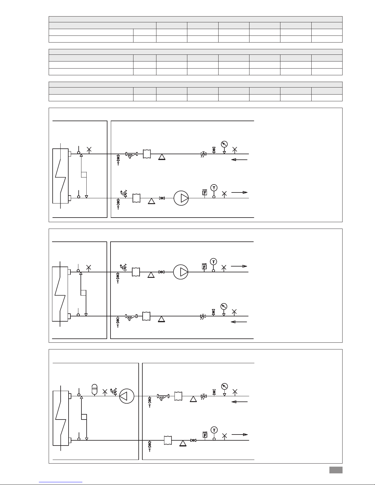
FACTORY CONNECTED INSTALLER CONNECTIONS
UTILITY
RETURN
UTILITY
OUTLET
12
12
14
14
2
10
2
4
3
5
11
6
1
15
15
7
15
8
12
13
System water circuit connection diagram, BRA2 version WITHOUT HYDRONIC KIT
1 PRESSURE GAUGE
2 VIBRATION-ISOLATING JOINT
3 SHUT-OFF VALVE
4 CALIBRATING VALVE
5 FLOW SWITCH
6 THERMOMETER
7 CIRCULATOR PUMP
8 SAFETY VALVE
9 EXPANSION VESSEL
10 MESH FILTER
11 FILL/TOP-UP
12 TEMPERATURE PROBE
13 DIFFERENTIAL PRESSURE
SWITCH
14 DRAIN/CHEMICAL WASHING
VALV E
15 SYSTEM VENT
FACTORY CONNECTED INSTALLER CONNECTIONS
UTILITY
RETURN
UTILITY
OUTLET
12
12
9
15
8
14
14
2
10
2
4
3
5
11
6
1
15
15
7
13
System water circuit connection diagram, BRA2 version WITHOUT HYDRONIC KIT
1 PRESSURE GAUGE
2 VIBRATION-ISOLATING JOINT
3 SHUT-OFF VALVE
4 CALIBRATING VALVE
5 FLOW SWITCH
6 THERMOMETER
7 CIRCULATOR PUMP
8 SAFETY VALVE
9 EXPANSION VESSEL
10 MESH FILTER
11 FILL/TOP-UP
12 TEMPERATURE PROBE
13 DIFFERENTIAL PRESSURE
SWITCH
14 DRAIN/CHEMICAL WASHING
VALV E
15 SYSTEM VENT
UTILITY
RETURN
UTILITY
OUTLET
FACTORY CONNECTED INSTALLER CONNECTIONS
12
121512
13
14
10
2
4
11
1
15
14
2
3
5
6
15
7
8
System water circuit connection diagram, BRN2 version WITH HYDRONIC KIT
1 PRESSURE GAUGE
2 VIBRATION-ISOLATING JOINT
3 SHUT-OFF VALVE
4 CALIBRATING VALVE
5 FLOW SWITCH
6 THERMOMETER
7 CIRCULATOR PUMP
8 SAFETY VALVE
9 EXPANSION VESSEL
10 MESH FILTER
11 FILL/TOP-UP
12 TEMPERATURE PROBE
13 DIFFERENTIAL PRESSURE
SWITCH
14 DRAIN/CHEMICAL WASHING
VALV E
15 SYSTEM VENT
Page 8
BRA2 - BRN2 EN
8
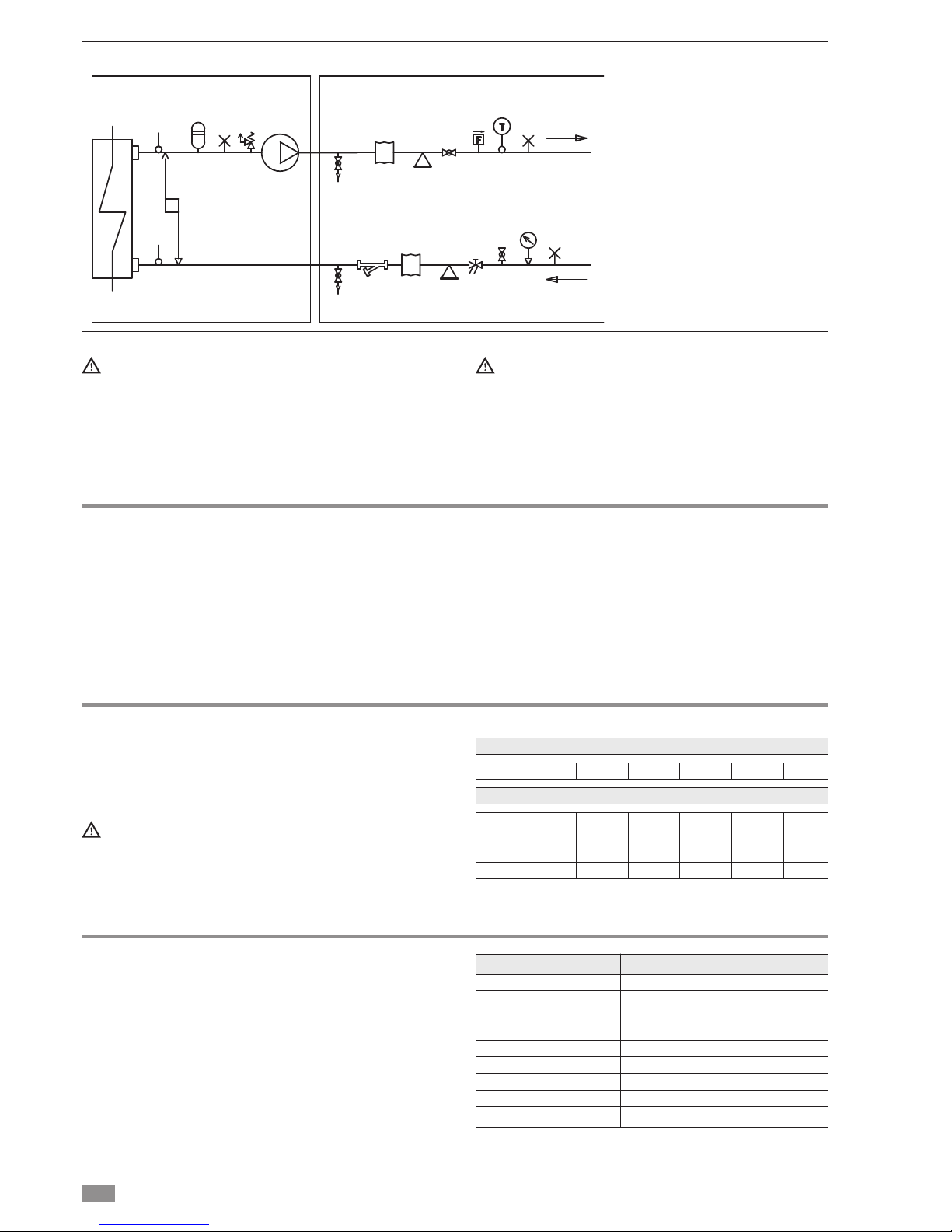
UTILITY
RETURN
UTILITY
OUTLET
FACTORY CONNECTED INSTALLER CONNECTIONS
12
12
15
8
7
13
14
2
3
5
6
15
14
10
2
4
11
1
15
System water circuit connection diagram, BRN2 version WITH HYDRONIC KIT
1 PRESSURE GAUGE
2 VIBRATION-ISOLATING JOINT
3 SHUT-OFF VALVE
4 CALIBRATING VALVE
5 FLOW SWITCH
6 THERMOMETER
7 CIRCULATOR PUMP
8 SAFETY VALVE
9 EXPANSION VESSEL
10 MESH FILTER
11 FILL/TOP-UP
12 TEMPERATURE PROBE
13 DIFFERENTIAL PRESSURE
SWITCH
14 DRAIN/CHEMICAL WASHING
VALV E
15 SYSTEM VENT
Must be provided with a filling/top-up system connected
to the return line and a drain cock in the lowest part of
the installation.
Installations containing antifreeze or covered by specific legislation must be fitted with water circuit disconnectors.
The manufacturer is not liable for obstruction, breakage
or noise resulting from the failure to install filters or
vibration dampers.
Particular types of water used for filling or topping up
must be treated with appropriate treatment systems.
For reference values, see the table.
Risk of freezing
The unit must be prevented from freezing at outside air temperatures around 0°C.
The following are recommended:
• use suitable percentages of antifreeze (see “Ethylene glycol solutions”)
• protect the piping with heating sheaths,
• empty the system, making sure no water remains at the
lowest points in the circuit or there are closed valves
where water may stagnate.
It is recommended to use non-toxic food grade antifreeze,
compliant with the standards in force in the countries where
the unit is used, if domestic hot water production is also featured.
The antifreeze used must be corrosion inhibited and compatible with the water circuit components.
Ethylene glycol solutions
Water and ethylene glycol solutions used as a heat carrier in
the place of water reduce the performance of the unit.
Multiply the performance figures by the values given in the
following table.
The heat pumps must be fitted with a filling/top-up system connected to the return line and a drain valve in the
lowest part of the system.
Systems containing antifreeze or covered by specific
legislation must be fitted with low-loss headers.
cPf
cQ
cdp
0
1
1
1
12%
0,985
1,02
1,07
20%
0,98
1,04
1,11
28%
0,974
1,075
1,18
35%
0,97
1,11
1,22
40%
0,965
1,14
1,24
0 -5 -10 -15 -20 -25
Freezing point (°C)
Percentage of ethylene glycol by weight
cPf: cooling capacity correction factor
cQ: flow rate correction factor
cdp: pressure drop correction factor
Water quality
The water used in the system and domestic hot water circuits must comply with the following characteristics:
PH 6-8
Electrical conductivity less than 200 mV/cm (25°C)
Chlorine ions less than 50 ppm
Sulphuric acid ions less than 50 ppm
Total iron less than 0.3 ppm
Alkalinity M less than 50 ppm
Total hardness less than 50 ppm
Sulphur ions none
Ammonia ions none
Silicon ions less than 30 ppm
Page 9
9
BRA2 - BRN2 EN
Condensate drain
In heating mode the unit produces a significant quantity of
condensate, which must be suitably drained.
Proceed as follows:
• Connect the unit condensate drain
• Make sure the drain hose has a incline of at least 2 cm/m,
without obstructions or choking.
• Connect the condensate drain hose to a rainwater drain.
Do not connect to the sewage system as odours may be
sucked up if the water in the drain trap evaporates.
• After connecting, check correct drainage of the condensate by pouring water into the pan.
• If necessary, suitably insulate the condensate drain hose.
• Condensate drainage must not cause problems to objects
or people.
• If the outside air temperature is less than 0°C, the condensate may freeze.
Use hot wires on the condensate drain hose downstream of
the unit to protect against frost.
C
AB
Safety valve
D
OUT
IN
C
AB
D
OUT
IN
Safety valve
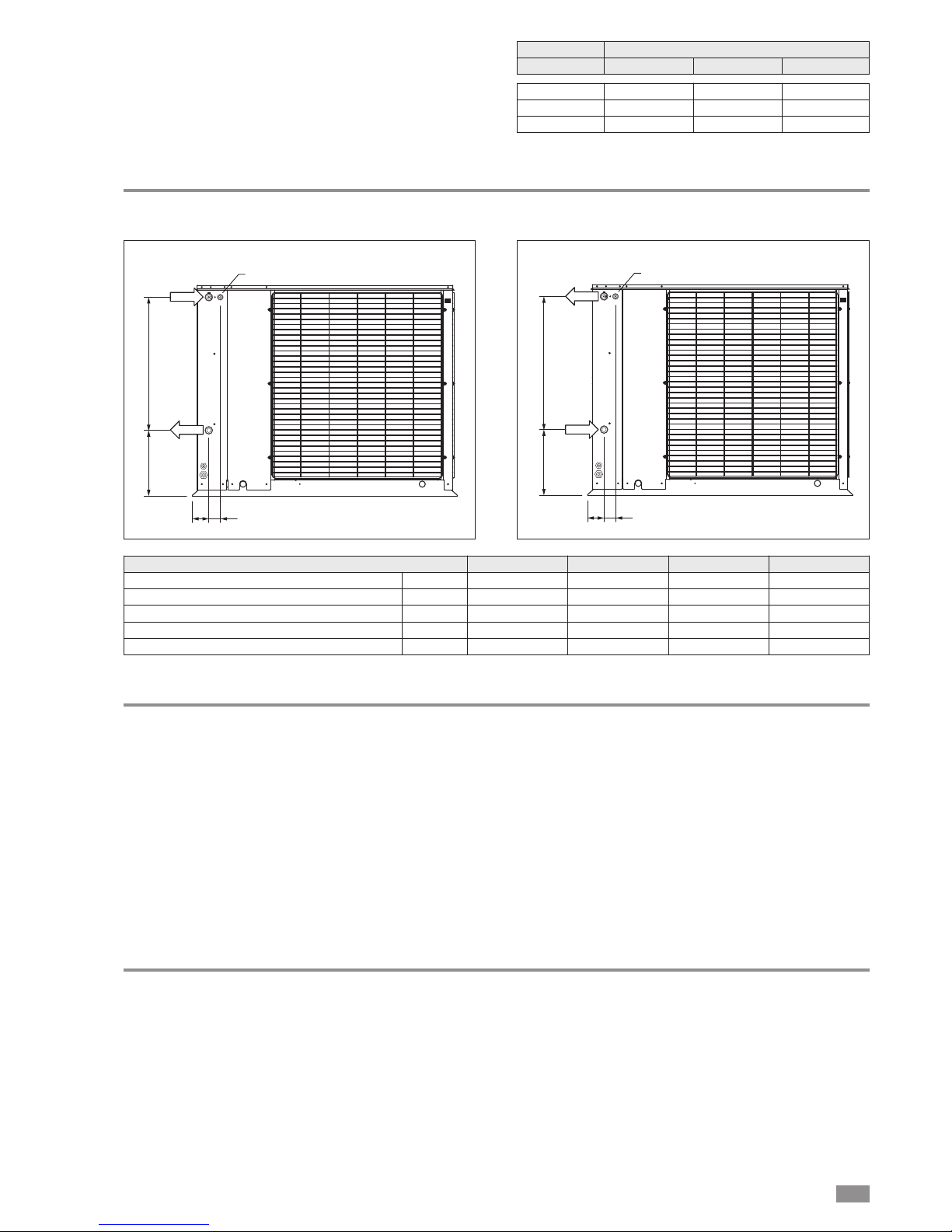
BRA2 BRN2
Dimensions
0021 0025-0031 0041-0051 0061
A mm 72 372 431 581
B mm 516 516 757 757
C mm 62 62 62 62
D* mm 65 65 65 65
Water connections in/out, male Ø 1” 1” 1”1/4 1”1/4
*D Safety valve connector position, only on the models with hydronic kit
SIZE AND POSITIONING OF CONNECTIONS, BRA2 AND BRN2
Fouling factors
The performance data given refer to conditions with clean
evaporator plates (fouling factor = 1).
For different fouling factors, multiply the figures in the performance tables by the coefficient given in the following table.
f1: capacity correction factor
fk1: compressor power input correction factor
fx1: total power input correction factor
4,4 x 10
-5
0,86 x 10
-4
1,72 x10
-4
0,96
0,93
0,99
0,98
0,99
0,98
Fouling factors
(m2°C/W) f1
Evaporator
fk1 fx1
Page 10

10
BRA2 - BRN2 EN
FILLING THE SYSTEM
- Before filling, check that the system drain valve is closed.
- Open all system and terminal air vents.
- Open system shut off valves.
- Start filling by slowly opening the system water fill cock
outside the unit.
- When water begins to leak out of the terminal air vent
valves, close them and continue filling until the pressure
gauge indicates a pressure of 1.5 bar.
The system must be filled to a pressure of between 1
and 2 bars.
It is recommended that this operation be repeated after
the unit has been operating for a number of hours. The
pressure of the system should be checked regularly and
if it drops below 1 bar, the water content should be
topped-up.
Check the tightness of the joints.
EMPTYING THE SYSTEM
- Before emptying, place the mains switch in the “off” position.
- Make sure the system fill/top-up water cock is closed.
- Open the drain cock outside the unit and all the system
and terminal air vent valves.
If the fluid in the circuit contains antifreeze, it should
not be allowed to drain freely, as it is pollutant.It should
be collected for possible reuse.When draining after heat
pump operation, take care as the water may be hot (up
to 50°).
Page 11
BRA2 - BRN2 EN
11
AIR DUCTING
I
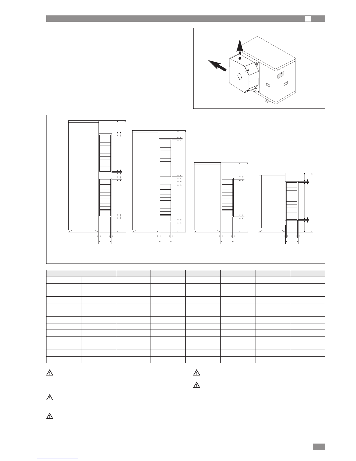
The BRA2-BRN2 models are designed for indoor and outdoor installation. The cooling air outlet can be ducted to the
outside
Ducting the air outlet
The air outlet ducting connection has the following characteristics.
A
B
A
B
C
G
LMNO
HI
D
EF
A
B
C
G
LMN O
HI
D
EF
A
B
C
G
LM
I
EF
A
B
C
G
L
M
I
EF
The length of the outlet ducts must be established by
qualified personnel, considering the performance of the
fan shown in the table "General technical data"
Suitable measures should be taken to avoid the bypass
of air between the outlet and intake.
For the heat pump appliances, the section of ducting
inside the environment must be suitably insulated.
Use vibration damper joints on the duct fittings.
The outlet is supplied as standard on the side; for sizes
0021 - 0031 only, the air outlet can be turned from the
side to the top position
Model 0061 Model 0041 - 0051 Model 0025 - 0031 Model 0021
BRA2 - BRN2 0021 0025 0031 0041 0051 0061
A mm 203 203 203 203 203 203
B mm 640 900 900 1240 1240 1390
C mm 486 556 556 521 521 521
D mm - - - 521 521 521
E mm 13 18 18 18,5 18,5 18,5
F mm 18 18 18 18 18 18
G mm 53 218 218 81,5 81,5 104
H mm - - - 11,5 11,5 121,5
I mm 62 127 127 27 27 52
L mm 19,5 19,5 19,5 19,5 19,5 19,5
M mm 19,5 19,5 19,5 19,5 19,5 19,5
N mm - - - 19,5 19,5 19,5
O mm - - - 19,5 19,5 19,5
Page 12
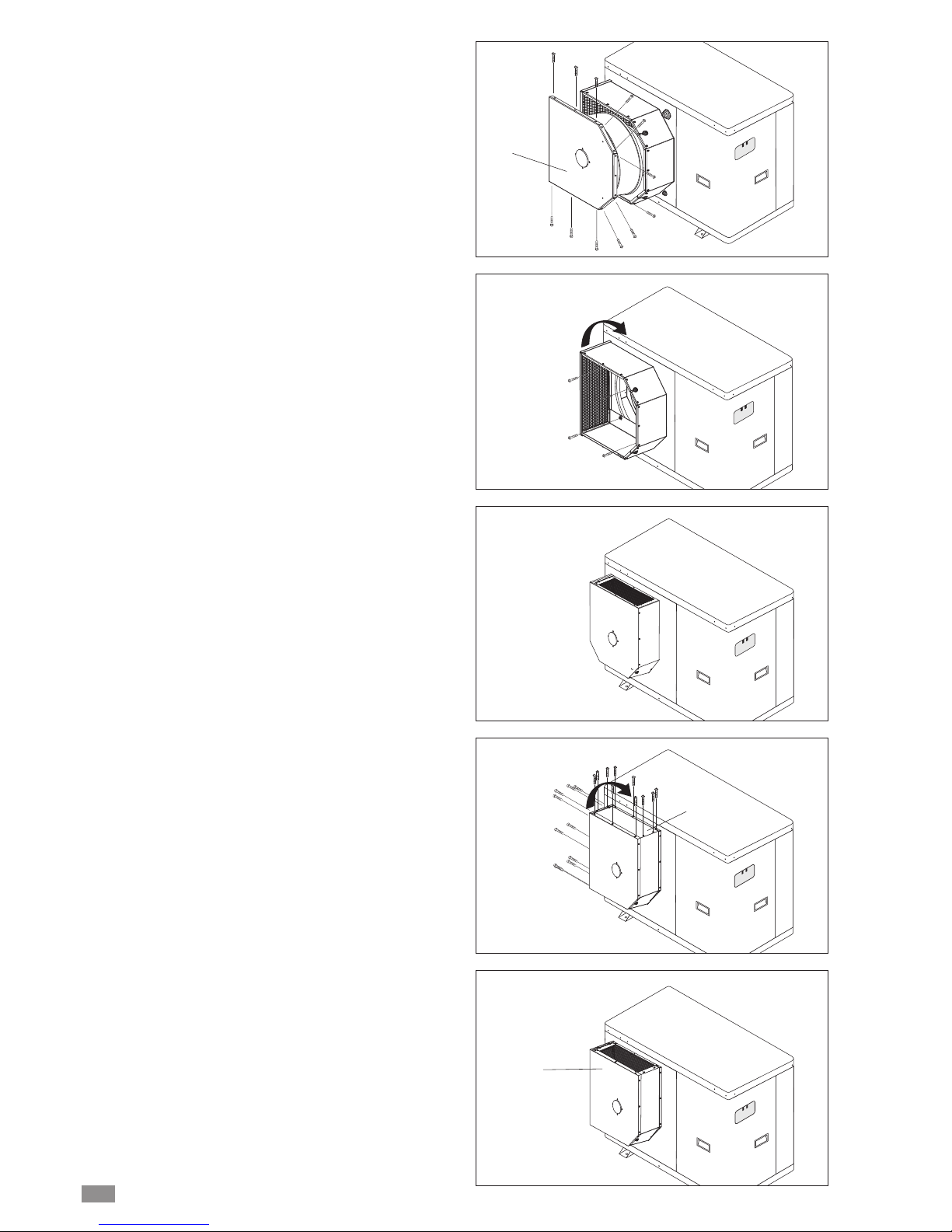
The appliance is factory fitted with the air outlet in position A
(side).
To move it to position B (top) for model 0021.
- Undo the fastening screws and remove the fan holder cover P on the air outlet collar.
- Unscrew the four fastening bolts and remove the air outlet
collar.
- Turn the air outlet collar 90° clockwise and fasten the four
bolts that were removed previously.
- Replace the fan holder cover P with the fan fitted and
tighten the fastening screws.
To move it to position B (top) for models 0025 - 0031.
- Undo the fastening screws and remove the protection grill.
- Undo the fastening screws and remove the closed panel F.
- Invert the protection grid G with the panel F.
- Tighten the fastening screws..
P
F
G
BRA2 - BRN2 EN
12
Page 13
BRA2 - BRN2 EN
13
ELECTRICAL CONNECTIONS
I A
The BRA2 and BRN2 units leave the factory already wired,
and require the installation of an omnipolar thermal overload
switch, a lockable mains disconnecting switch for the connection to the mains power supply, and the connection of
the flow switch to the corresponding terminals. All the above
operations must be carried out by qualified personnel
in compliance with the legislation in force.
For all electrical work, refer to the electrical wiring diagrams
in this manual.You are also recommended to check:
- that the characteristics of the mains electricity supply are
adequate for the absorptions indicated in the electrical
characteristics table below, also bearing in mind
Power to the unit must be turned on only after installation work (hydraulic and electrical) has been completed.
All electrical connections must be carried out by qualified personnel in accordance with legislation in force in
the country concerned.
Respect instructions for connecting phase, neutral and
earth conductors.
The power line should be fitted upstream with a suitable
device to protect against short-circuits and leakage to
earth, isolating the installation from other equipment.
Voltage must be within a tolerance of ±10% of the rated
power supply voltage for the unit (for three phase units,
the unbalance between the phases must not exceed
2%). If these parameters are not respected, contact the
electricity supply company.
For electrical connections, use double insulation cable
in conformity with current legislation in the country concerned.
An omnipolar thermal overload switch and a lockable mains
disconnecting switch, in compliance with the CEI-EN standards (contact opening of at least 3mm), with adequate
switching and residual current protection capacity based on
the electrical data table shown below,must be installed as
near as possible to the appliance.
The devices on the unit must be lockable.
An efficient earth connection is obligatory. Failure to
earth the appliance absolves the manufacturer of all liability for damage.
In the case of three phase units, ensure the phases
are connected correctly.
Do not use water pipes to earth the unit.
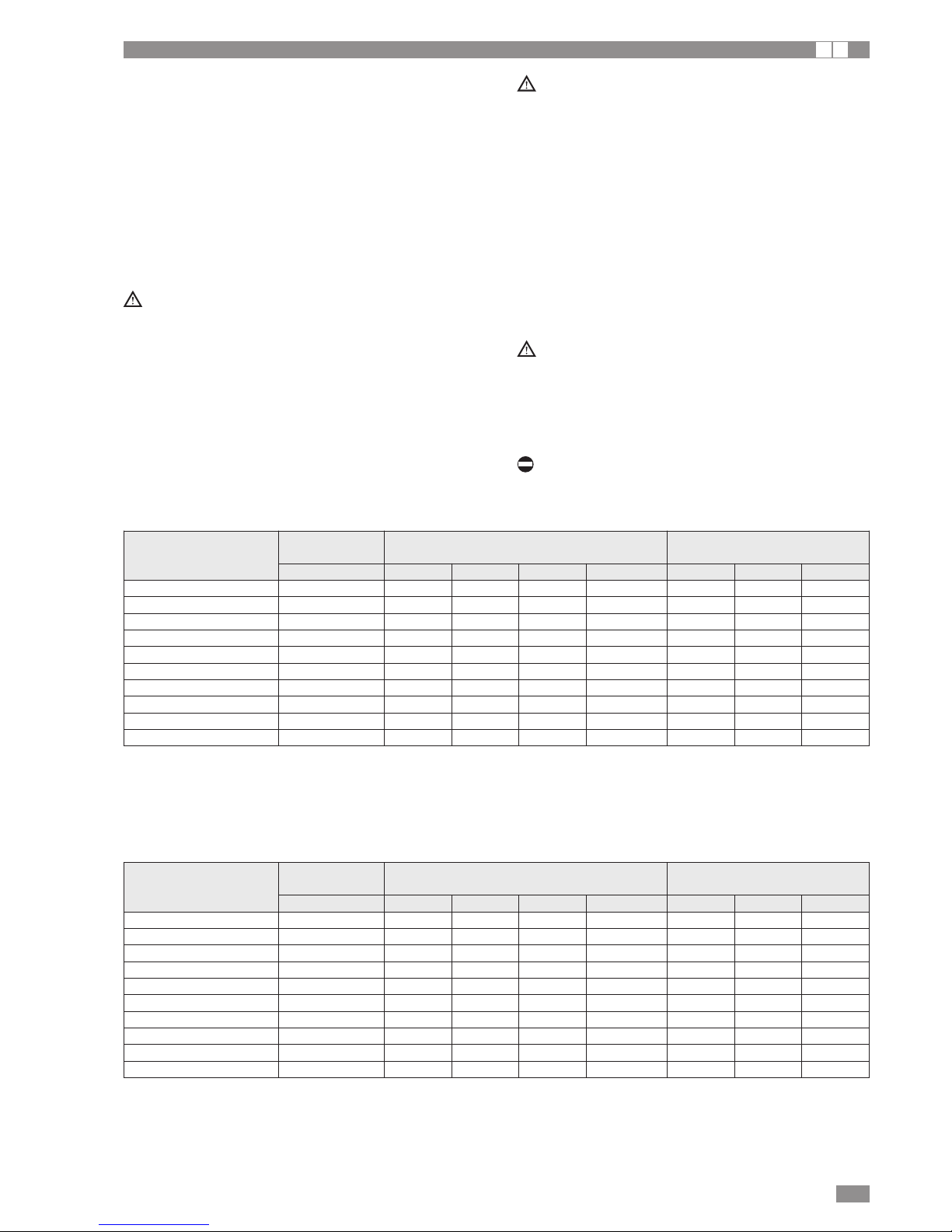
ELECTRICAL DATA, BRA2 AND BRN2 WITHOUT HYDRONIC KIT
F.L.I. Maximum power input
F.L.A. Maximum current input
S.A. Start-up current
S.A. LIM Peak current with peak limiter
Maximum values for sizing the protection switches and power supply cables
Size
Power supply Maximum values Fuses (5x20T 250V)
(V-Ph-Hz) FLA [A] FLI [kW] SA [A] SA LIM [A] FU1 FU2 FU3
BRA2 - BRN2 0021 230-1N-50 18,4 3,42 63,4 29,4 4A 3,15A 2A
BRA2 - BRN2 0025 230-1N-50 21,4 4,19 84,4 39,4 4A 3,15A 2A
BRA2 - BRN2 0031 230-1N-50 25,4 5,09 99,4 46,4 4A 3,15A 2A
BRA2 - BRN2 0041 230-1N-50 29,4 6,34 134,7 49,7 4A 6,3A 2A
BRA2 - BRN2 0021 400-3N-50 7,9 3,42 34,4 20,4 4A 3,15A 2A
BRA2 - BRN2 0025 400-3N-50 8,4 3,95 37,4 21,4 4A 3,15A 2A
BRA2 - BRN2 0031 400-3N-50 10,4 4,76 50,4 28,4 4A 3,15A 2A
BRA2 - BRN2 0041 400-3N-50 12,4 6,36 68,7 39,7 4A 6,3A 2A
BRA2 - BRN2 0051 400-3N-50 14,2 6,42 68,7 39,7 4A 6,3A 2A
BRA2 - BRN2 0061 400-3N-50 17,4 7,75 78,7 45,7 4A 6,3A 2A
ELECTRICAL DATA, BRA2 AND BRN2 WITH HYDRONIC KIT
F.L.I. Maximum power input
F.L.A. Maximum current input
S.A. Start-up current
S.A. LIM Peak current with peak limiter
Maximum values for sizing the protection switches and power supply cables
Size
Power supply Maximum values Fuses (5x20T 250V)
(V-Ph-Hz) FLA [A] FLI [kW] SA [A] SA LIM [A] FU1 FU2 FU3
BRA2 - BRN2 0021 230-1N-50 19,0 3,50 64,0 30,0 1,25A 1,25A 2A
BRA2 - BRN2 0025 230-1N-50 22,0 4,27 92,2 40,0 1,25A 3,15A 2A
BRA2 - BRN2 0031 230-1N-50 26,0 5,17 100,0 47,0 1,25A 3,15A 2A
BRA2 - BRN2 0041 230-1N-50 30,3 6,47 135,7 50,7 1,25A 6,3A 2A
BRA2 - BRN2 0021 400-3N-50 8,5 3,50 35,0 21,0 1,25A 1,25A 2A
BRA2 - BRN2 0025 400-3N-50 9,0 4,03 38,0 22,0 1,25A 3,15A 2A
BRA2 - BRN2 0031 400-3N-50 11,0 4,84 51,0 29,0 1,25A 3,15A 2A
BRA2 - BRN2 0041 400-3N-50 13,3 6,49 69,7 40,7 1,25A 6,3A 2A
BRA2 - BRN2 0051 400-3N-50 15,1 6,55 69,7 40,7 1,25A 6,3A 2A
BRA2 - BRN2 0061 400-3N-50 18,3 7,88 79,7 46,7 1,25A 6,3A 2A
Page 14
BRA2 - BRN2 EN
14
MAINS POWER SUPPLY CONNECTIONS
I A
• Before connecting the unit to the power supply, makes
sure that switch QF1 is open, suitably padlocked and
marked.
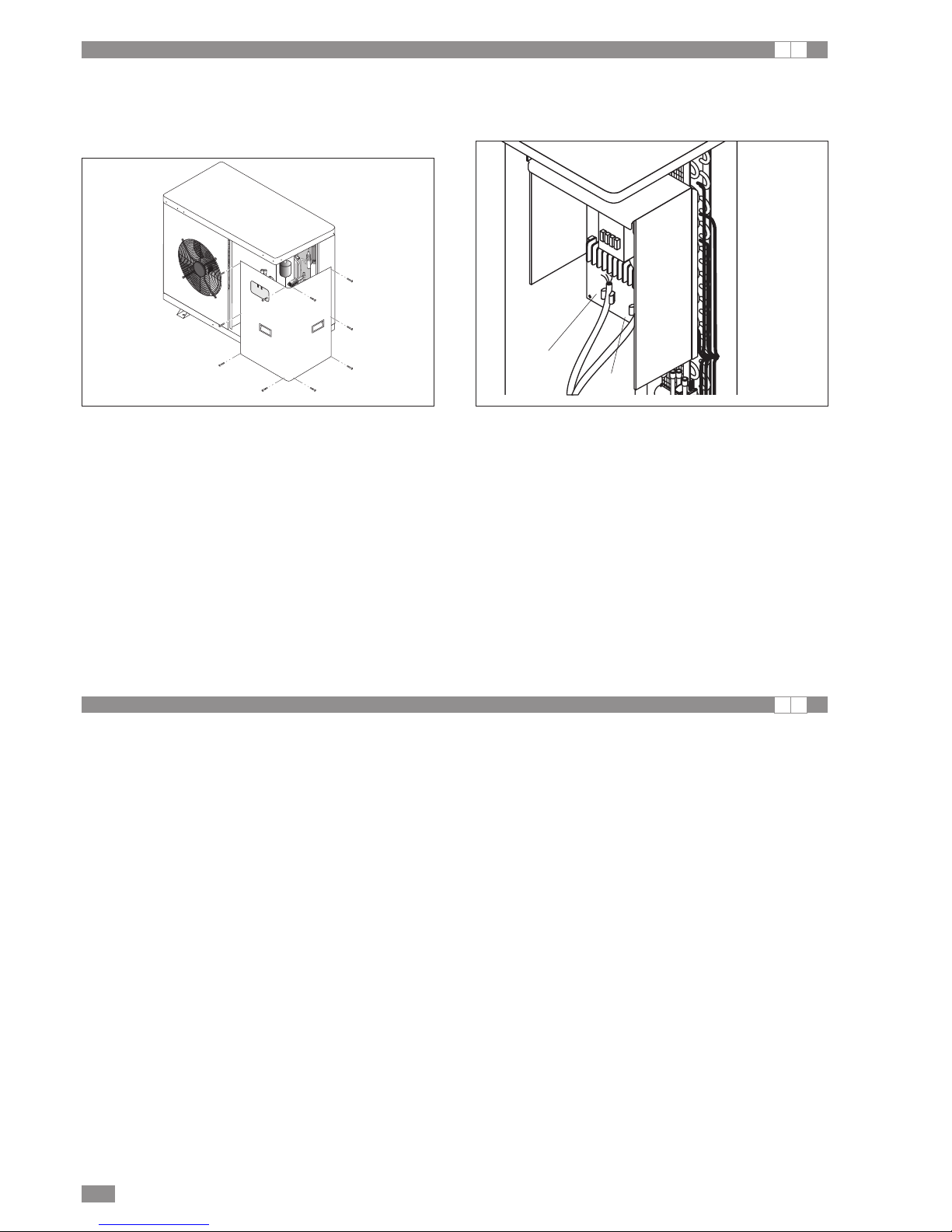
• Remove the inspection panel by unscrewing the screws.
• Use cable gland A for the main electrical power cable and
cable gland B for other external cables to be connected by
the installer.
• Identify the terminals used for electrical connections on
the layout drawing shown in this manual.
• Make the connections as shown on the wiring diagram
enclosed with the product.
• Replace the covers on the electrical panel and the closing
panel.
• Make sure that all the covers removed to make the electrical connections have been replaced before powering up
the unit.
• Position the main switch QF1 (outside the unit) in the “ON”
position.
A
B
INSTALLER CONNECTIONS
I A
All terminals referred to in the explanations below are to be
found on the terminal block inside the electrical panel and
described as “installer terminals” (see the wiring diagram
enclosed with the product).
REMOTE ON/OFF (SA1)
To use a remote on/off device, an external contactor must
be connected to installer terminals 14 and 15, setting parameter CL42 to -1 (CL42=-1).
For timed operation, connect a daily or weekly timer
between terminals 14 and 15.
REMOTE ALARM (RD1)
For remote display of unit shut-down, an audible or visual
alarm warning device can be connected between terminals
12 and 13.
Connect the phase to terminal 13 and the alarm signal
device between terminal 13 and the neutral (maximum load
applicable 500 mA at 24 V).
REMOTE COOLING/HEATING CHANGEOVER (SA2)
To use a remote cooling/heating changeover device, connect the contact of the device to installer terminals 16 and
17. To activate the device, proceed as follows:
- From the HSW15 control panel select parameter CL43
and set it to the value +3 (contact closed = cooling, contact open = heating) or -3 (contact closed = heating, contact open = cooling)
COMPRESSOR ON SIGNAL (GN1)
For remote display of compressor operating status, an audible or visual alarm warning device can be connected
between terminals 10 and 11. Connect the phase to terminal
11 and the signal device between terminal 10 and the neutral.
Page 15
15
BRA2 - BRN2 EN
OUTSIDE AIR PROBE (BT3) (Accessory)
The outside air probe allows the system water temperature
set point to be compensated during heating or cooling operation.
Installation instructions
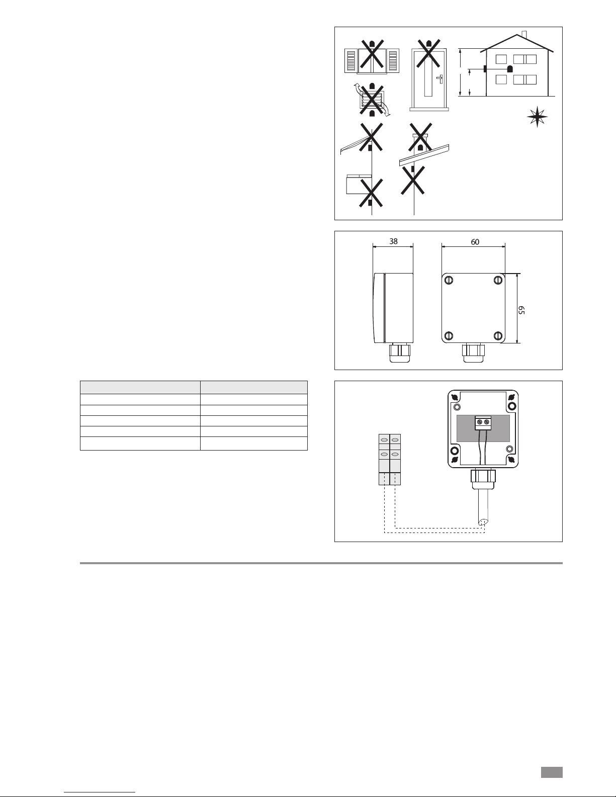
The outside air probe must be installed:
• outside of the home
• not in direct sunlight, away from flue gas discharges, air
outlets, or doors and windows.
• on a perimeter wall facing north/north-west
• at a minimum height of 2.5 metres above the ground or at
most half way up the house.
H
H
2
/
1
N
N-W
m 5,2nim
Mounting method:
• Open the cover of the sensor.
• Attach a probe to the wall and the correct position as
described above.
• For the electrical connections see “Connection diagram”.
• Re-place the cover of the sensor.
TECHNICAL DATA
Sensing element NTC 10Kohm ± 1% (25°C)
Degree of protection IP65
Perm. ambient / carriage temperatur
e -50°C...+100°C
Measuring range -50°C...+100°C
Materials PA 15% GK, Colour RAL 9010
12
20 21
BT3
REMOTE KEYPAD KIT (A5) (Accessory)
The remote keypad kit can be used to display all unit functions and access the parameters of the electronic board
from a point located at some distance from the unit itself.
It consists of a remote control module.
To install the kit, proceed as follows:
- access the unit’s electrical panel after having disconnected the power supply;
- connect the remote control module with 3 wires to terminals 22, 23 and 24 on the installer terminal block:
- terminal 22 connected to the GND terminal on the module;
- terminal 23 connected to the Signal terminal on the module;
- terminal 24 connected to the +12V DC terminal on the
module;
FLOW SWITCH CONNECTION (F3)
The system flow switch must be connected to terminals 18
and 19.
If this is not connected, the unit will not be able to operate
and the controller will display alarm code ER20 (see "Displaying alarms").
Page 16
BRA2 - BRN2 EN
16
GENERAL TECHNICAL DATA
I A
BRA2 without hydronic kit 0021 0025 0031 0041 0021 0025 0031 0041 0051 0061
Cooling capacity 1 [kW] 7,71 9,50 11,5 15,0 7,70 9,0 11,60 15,7 17,9 20,5
Power consumption 1 [kW] 2,29 2,79 3,80 4,60 2,22 2,59 3,55 4,79 5,19 6,03
COP 1 3,37 3,41 3,03 3,26 3,47 3,47 3,27 3,28 3,45 3,40
Cooling capacity 2 [kW] 5,74 7,03 8,68 11,4 5,72 7,10 8,76 11,8 13,3 15,6
Power consumption 2 [kW] 2,22 2,68 3,60 4,33 2,17 2,54 3,32 4,47 5,00 5,57
EER 2 2,59 2,62 2,41 2,63 2,63 2,80 2,64 2,64 2,66 2,80
ESEER 1 3,11 3,22 2,98 3,06 3,21 3,45 3,16 3,13 3,02 3,26
Flow-rate 1 m3/h 1,33 1,63 1,98 2,58 1,32 1,55 2,00 2,70 3,08 3,53
Pressure drop 1 kPa 13 15 16 31 13 14 16 34 36 35
Flow-rate 2 m3/h 0,99 1,21 1,49 1,96 0,98 1,22 1,51 2,03 2,29 2,68
Pressure drop 2 kPa 7 8 9 18 7 8 9 19 20 20
Sound power 4 [dBA] 75 75 75 77 75 75 75 77 77 77
Power supply V-N/Ph-Hz 230-1N-50 400-3N-50
No. of compressors 1 1 1 1 1 1 1 1 1 1
No. of circuits 1 1 1 1 1 1 1 1 1 1
Type of compressor Scroll
No. of fans 1 1 1 2 1 1 1 2 2 2
Air flow-rate 1 [m3/h] 3000 3400 3400 6450 3000 3400 3400 6450 6000 6350
No. of system heat exchangers 1 1 1 1 1 1 1 1 1 1
Type of system heat exchanger PLATE
System water heat exchanger content l 2 2 2 2 2 2 2 2 2 3
BRA2 with hydronic kit 0021 0025 0031 0041 0021 0025 0031 0041 0051 0061
Cooling capacity 1 [kW] 7,76 9,56 11,6 15,1 7,75 9,1 11,70 15,8 18,0 20,7
Power consumption 1 [kW] 2,21 2,69 3,71 4,48 2,14 2,50 3,45 4,66 5,04 5,91
COP 1 3,51 3,55 3,13 3,37 3,62 3,62 3,39 3,39 3,57 3,50
Cooling capacity 2 [kW] 5,77 7,08 8,73 11,5 5,75 7,15 8,81 11,9 13,4 15,7
Power consumption 2 [kW] 2,16 2,61 3,52 4,26 2,11 2,47 3,24 4,41 4,91 5,45
EER 2 2,67 2,71 2,48 2,70 2,72 2,90 2,72 2,70 2,73 2,88
ESEER 1 3,21 3,35 3,07 3,14 3,33 3,59 3,27 3,23 3,11 3,37
Flow-rate 1 m3/h 1,33 1,64 2,00 2,60 1,33 1,56 2,01 2,72 3,10 3,56
Available pressure head 1 kPa 59 50 40 37 60 53 39 33 26 23
Flow-rate 2 m3/h 0,99 1,22 1,50 1,98 0,99 1,23 1,52 2,05 2,30 2,70
Available pressure head 2 kPa 72 66 59 51 72 66 59 50 49 47
Sound power [dBA] 75 75 75 77 75 75 75 77 77 77
Power supply V-N/Ph-Hz 230-1N-50 400-3N-50
No. of compressors 1 1 1 1 1 1 1 1 1 1
No. of circuits 1 1 1 1 1 1 1 1 1 1
Type of compressor Scroll
No. of fans 1 1 1 2 1 1 1 2 2 2
Air flow-rate [m3/h] 3000 3400 3400 6450 3000 3400 3400 6450 6000 6350
No. of system heat exchangers 1 1 1 1 1 1 1 1 1 1
Type of system heat exchanger PLATE
System water heat exchanger content l 2 2 2 2 2 2 2 2 2 3
(1) outside air 35°C evaporator water IN/OUT 23/18°C
(2) outside air 35°C evaporator water IN/OUT 12/7°C
(3) maximum and minimum operating pressure refer to activation of the pressure switches
(4) sound power based on measurements performed in accordance with ISO 9614 and Eurovent 8/1
Performance in accordance with EN 14511:2013
(1) outside air 35°C evaporator water IN/OUT 23/18°C
(2) outside air 35°C evaporator water IN/OUT 12/7°C
(3) maximum and minimum operating pressure refer to activation of the pressure switches
(4) Sound power based on measurements performed in accordance with ISO 9614 and Eurovent 8/1
Performance in accordance with EN 14511:2013
Page 17
17
BRA2 - BRN2 EN
GENERAL TECHNICAL DATA
I A
BRN2 without hydronic kit 0021 0025 0031 0041 0021 0025 0031 0041 0051 0061
Heating capacity 1 [kW] 6,76 8,37 10,5 12,9 6,73 8,3 10,00 13,4 14,8 17,3
Power consumption 1 [kW] 2,25 2,84 3,48 4,35 2,24 2,69 3,23 4,47 4,67 5,58
COP 1 3,01 2,95 3,01 2,97 3,01 3,08 3,10 2,99 3,17 3,10
Cooling capacity 2 [kW] 4,81 5,89 7,29 9,6 4,80 5,99 7,35 10,0 11,1 13,0
Power consumption 2 [kW] 1,96 2,39 3,27 3,81 1,92 2,27 2,99 3,95 4,42 4,95
EER 2 2,45 2,46 2,23 2,51 2,50 2,64 2,46 2,52 2,51 2,63
ESEER 1 3,07 3,05 2,87 3,03 3,09 3,29 2,99 3,09 2,85 3,11
Flow-rate 1 m3/h 1,16 1,44 1,80 2,22 1,16 1,43 1,72 2,30 2,55 2,98
Pressure drop 1 kPa 10 12 13 23 10 12 12 25 24 24
Flow-rate 2 m3/h 0,83 1,01 1,25 1,64 0,83 1,03 1,26 1,71 1,91 2,24
Pressure drop 2 kPa 5 6 6 13 5 6 6 14 14 14
Sound power 4 [dBA] 75 75 75 77 75 75 75 77 77 77
Power supply V-N/Ph-Hz 230-1N-50 400-3N-50
No. of compressors 1 1 1 1 1 1 1 1 1 1
No. of circuits 1 1 1 1 1 1 1 1 1 1
Type of compressor Scroll
No. of fans 1 1 1 2 1 1 1 2 2 2
Air flow-rate 1 [m3/h] 3000 3400 3400 6450 3000 3400 3400 6450 6000 6350
No. of system heat exchangers 1 1 1 1 1 1 1 1 1 1
Type of system heat exchanger PIASTRE
System water heat exchanger content l 2 2 2 2 2 2 2 2 2 3
BRN2 with hydronic kit 0021 0025 0031 0041 0021 0025 0031 0041 0051 0061
Heating capacity 1 [kW] 6,72 8,32 10,4 12,8 6,68 8,2 9,99 13,3 14,8 17,2
Power consumption 1 [kW] 2,18 2,75 3,38 4,22 2,17 2,61 3,14 4,38 4,57 5,46
COP 1 3,08 3,02 3,08 3,03 3,08 3,16 3,18 3,04 3,24 3,15
Cooling capacity 2 [kW] 4,83 5,93 7,33 9,6 4,82 6,03 7,39 10,0 11,2 13,1
Power consumption 2 [kW] 1,92 2,34 3,19 3,76 1,88 2,22 2,91 3,88 4,38 4,85
EER 2 2,51 2,53 2,30 2,56 2,56 2,72 2,54 2,58 2,56 2,70
ESEER 1 3,17 3,17 2,97 3,09 3,19 3,43 3,09 3,14 2,93 3,20
Flow-rate 1 m3/h 1,16 1,43 1,79 2,20 1,15 1,42 1,72 2,29 2,55 2,96
Available pressure head 1 kPa 66 58 48 46 66 58 51 44 44 40
Flow-rate 2 m3/h 0,83 1,02 1,26 1,65 0,83 1,04 1,27 1,72 1,93 2,25
Available pressure head 2 kPa 74 73 67 56 74 73 67 55 55 55
Sound power [dBA] 75 75 75 77 75 75 75 77 77 77
Power supply V-N/Ph-Hz 230-1N-50 400-3N-50
No. of compressors 1 1 1 1 1 1 1 1 1 1
No. of circuits 1 1 1 1 1 1 1 1 1 1
Type of compressor Scroll
No. of fans 1 1 1 2 1 1 1 2 2 2
Air flow-rate [m3/h] 3000 3400 3400 6450 3000 3400 3400 6450 6000 6350
No. of system heat exchangers 1 1 1 1 1 1 1 1 1 1
Type of system heat exchanger PLATE
System water heat exchanger content l 2 2 2 2 2 2 2 2 2 3
(1) outside air 7°C; condenser water in/out 40/45°C
(2) outside air 35°C; evaporator water IN/OUT 12/7°C
(3) maximum and minimum operating pressure refer to activation of the pressure switches
(4) Sound power based on measurements performed in accordance with ISO 9614 and Eurovent 8/1
Performance in accordance with EN 14511:2013
(1) outside air 7°C; condenser water in/out 40/45°C
(2) outside air 35°C; evaporator water IN/OUT 12/7°C
(3) maximum and minimum operating pressure refer to activation of the pressure switches
(4) Sound power based on measurements performed in accordance with ISO 9614 and Eurovent 8/1
Performance in accordance with EN 14511:2013
Page 18
18
BRA2 - BRN2 EN
OPERATING LIMITS
U I A
-15
-10
-5
0
5
10
15
20
25
30
35
40
45
50
-15 -10 -5 0 5 10 15 20
Outside air temperature [°C]
Water outlet temperature at evaporator [°C]
COOLING
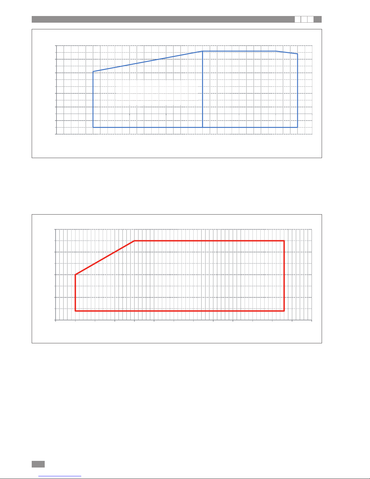
Operating range in COOLING
Water temperature head min-max= 3-8 K
Water circuit pressure min-max= 1÷6 bars
Max storage temperature= 63°C
Maximum percentage of glycol= 40%
As standard, the unit is manufactured with operating parameters allowing water produced at the evaporator down to +5°C. If needing to produce
water down to -10°C, contact technical service.
OPERATION WITH
WATER-GLYCOL MIX
20
25
30
35
40
45
50
55
60
-15 -10 -5 0 5 10 15 20 25 30 35 40 45 50
Water outlet temperature at condenser [°C]
Outside air temperature [°C]
HEATING
Operating range in heating
Water temperature head min-max= 4-10 K
Water circuit pressure min-max= 1÷6 bars
Maximum water temperature at system heat exchanger water inlet +50°C
Max storage temperature= 63°C
Maximum percentage of glycol= 40%
Page 19
BRA2 - BRN2 EN
19
U I A
PRESSURE DROP AND PRESSURE HEAD AVAILABLE TO SYSTEM
I A
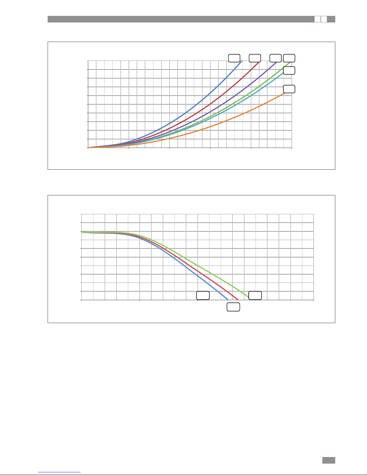
SYSTEM HEAT EXCHANGER PRESSURE DROP, UNIT WITHOUT HYDRONIC KIT
0
10
20
30
40
50
60
70
80
90
100
012345
Pressure drop [kPa]
System heat exchanger pressure drop
Water flow-rate [m3/h]
0021 0025 0041 0031
0051
0061
AVAILABLE PRESSURE HEAD, UNIT WITH HYDRONIC KIT
0
10
20
30
40
50
60
70
80
90
100
01234
Available pressure head [kPa]
Water flow-rate [m3/h]
Available pressure head
0025
0021 0031
Page 20
BRA2 - BRN2 EN
20
U I A
PRESSURE DROP AND PRESSURE HEAD AVAILABLE TO SYSTEM
I A
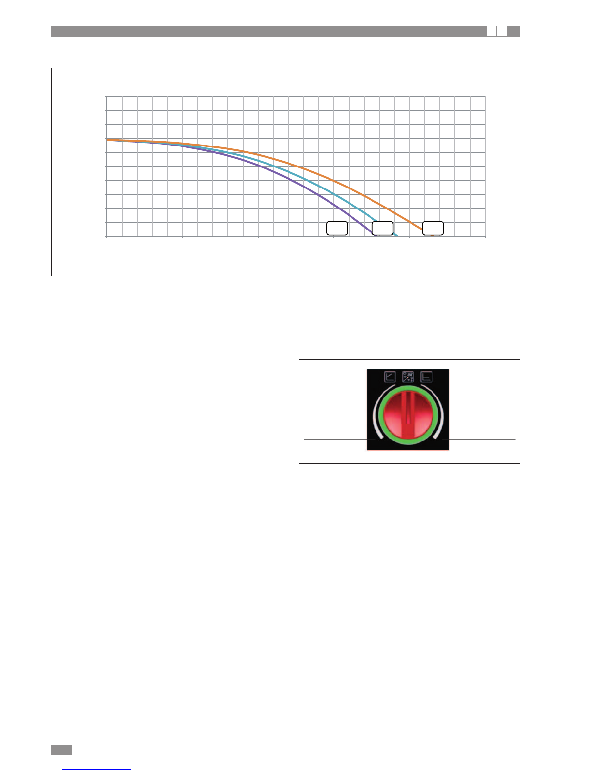
AVAILABLE PRESSURE HEAD, UNIT WITH HYDRONIC KIT
0
10
20
30
40
50
60
70
80
90
100
012345
Available pressure head [kPa]
Water flow-rate [m3/h]
Presión estática útil
0051 0041 0061
The pressure head refers to the value available to the system.
The pump installed on the unit, if the “hydronic kit” option is
purchased as an accessory, is a circulator pump with built-in
inverter, including water pressure transducer and microprocessor to manage the following control modes adjustment:
CONSTANT ΔP: the pressure differential between pump
suction and discharge is kept constant, pump speed
decreases progressively when the terminals close.
VARIABLE ΔP: the pressure differential reduces as flowrate decreases, to account for the lower pressure drop along
the piping running to the terminals (recommended for long
sections of piping)
The type of control can be set using the selector on the
pump body. As standard, the type of control is set to CONSTANT ΔP.
CONSTANT ΔP
(standard setting)
VARIABLE ΔP
Page 21
300
250
200
150
100
50
0
2000 2100 2200 2300 2400 2500 2600 2700 2800 2900 3000 3100 3200 3300 3400 3500
0051
0041
0061
21
BRA2 - BRN2 EN
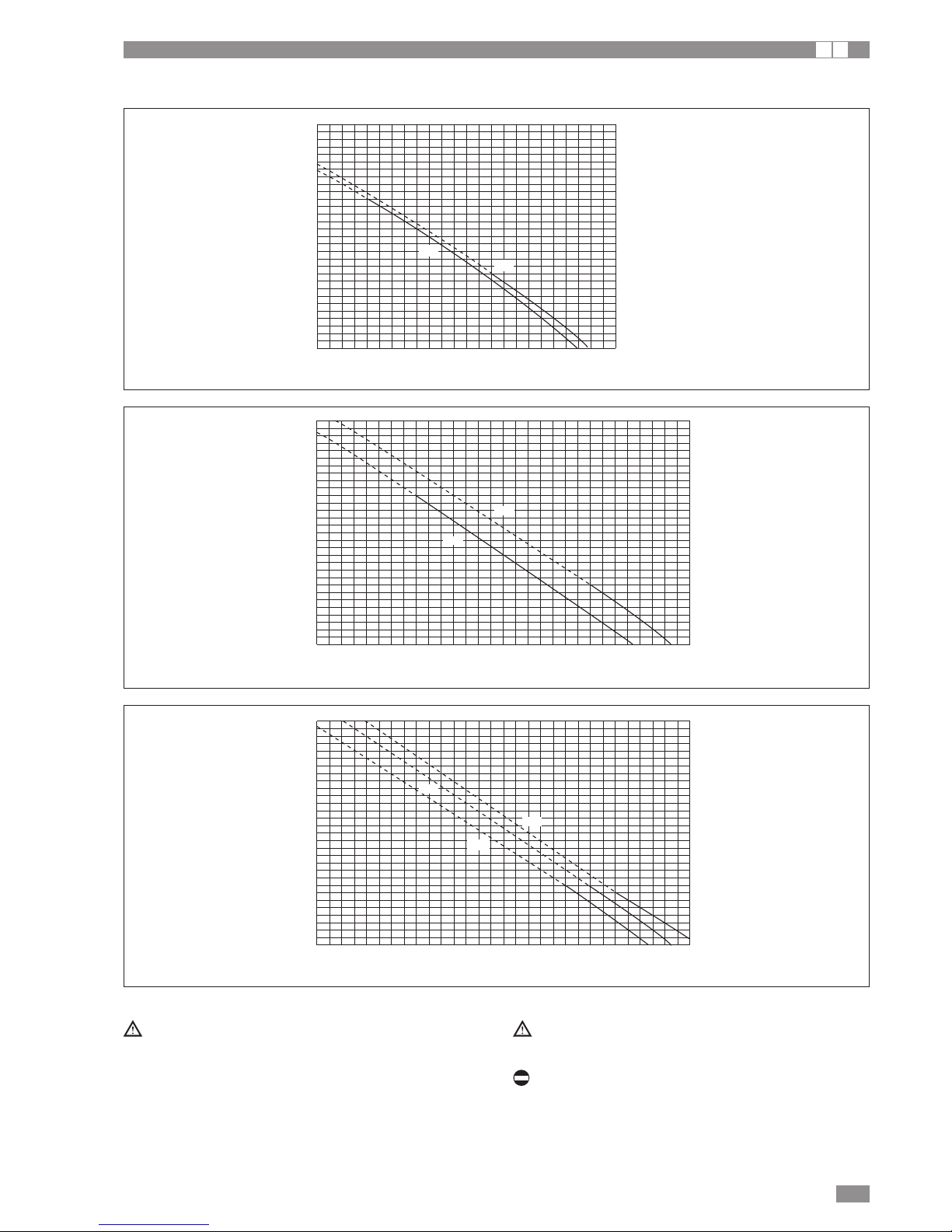
The characteristics indicated above refer to units with
ducted outlets, with a 0.5m long straight duct and a
cross-section equal to the cross-section of the fan.
The BRA2-BRN2 0041÷0061 units are supplied with two
fans
Do not operate in the dashed section of the curves.
Air flow-rate (
m3/h)
300
250
200
150
100
50
0
2000 2100 2200 2300 2400 2500 2600 2700 2800 2900 3000 3100 3200
0011
0021
GRAPH OF FLOW-RATE - FAN PRESSURE GAIN
MOD. 0021
Residual static pressure gain (Pa)
Air flow-rate (
m3/h)
300
250
200
150
100
50
0
2000 2100 2200 2300 2400 2500 2600 2700 2800 2900 3000 3100 3200 3300 3400 3500
0031
0025
MOD. 0041-0061
MOD. 0025 - 0031
Residual static pressure gain (Pa)Residual static pressure gain (Pa)
Air flow-rate (
m3/h)
FAN PRESSURE GAIN CURVES
I A
Page 22
22
BRA2 - BRN2 EN
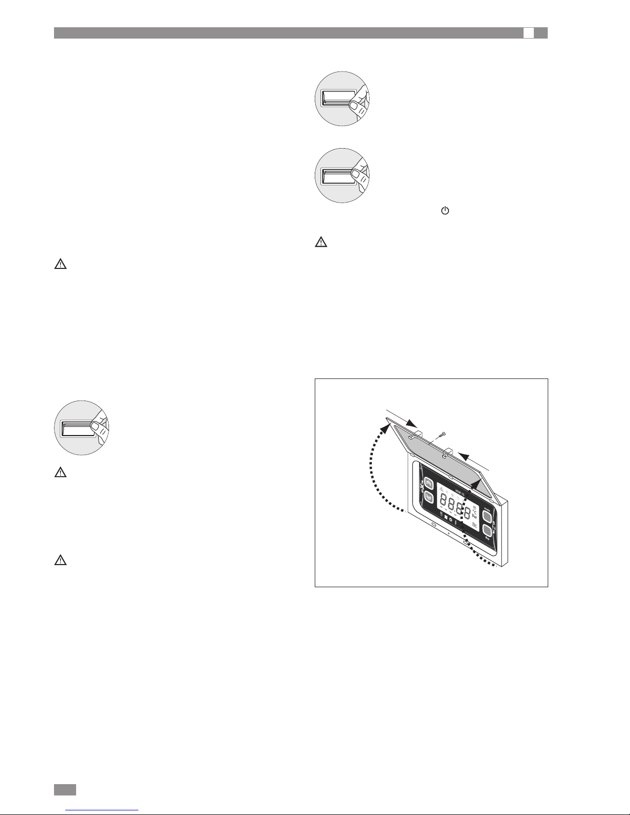
CHECKING AND STARTING UP THE UNIT
A
PREPARING FOR FIRST START UP or restarting
after shutting down for long periods.
The unit must be started up for the first time by the Technical Service.
Before starting up the units, make sure that:
- All safety conditions have been respected;
- The unit is adequately fixed to the surface it rests on;
- Clearances have been respected
- Water connections have been carried out as indicated in
the instruction manual;
- The water circuit is filled and vented.
- The water valves are open;
- Electrical connections have been carried out correctly
- Voltage is within a tolerance of 10% of the rated voltage
for the unit;
- The unit is correctly earthed;
- All electrical connections are tight and all water connections have been carried out correctly.
The unit must be started up for the first time with standard
settings. Set Point values may be modified only after testing
has been completed.
Before starting up, power up the unit for at least two hours
by switching QF1 and QS1 ON (see "wiring diagram" and
the control panel in standby) so as to allow the oil in the
compressor sump to heat up.
STARTING UP FOR THE FIRST TIME (after two hours)
Before starting the chiller:
-
Make sure the switch QF1 is in the OFF
position.
- Make sure the contact of the on/off device
SA1 (see the wiring diagram) is open (if featured).
- Close the door of the electrical panel.
- Move the main unit switch QS1 to the ON
position.
- Move the switch QF1 (outside the unit) to
“ON”.
-
The icon with the off symbol ( ) lights up on the control
panel, indicating power is connected.
For the position of internal components, see the diagrams.
ON
OFF
ON
OFF
ACTIVATING AND DEACTIVATING THE UNIT
- Move the contact on the on/off device SA1
(if featured) to ON.
During this phase, if the following indications appear on
the display, follow the instructions:
- ER20 check the water flow-rate and the connection of
the flow switch.
- ER01 (three-phase heat pumps only): check the power
supply connection and if necessary reverse two phases.
At every change of season, make sure the operating
conditions fall within the limits specified.
Make sure the current input of the compressor is less
than the maximum shown in the table of technical specifications.
Make sure the voltage is within the established limits and
that, for three phase units, the unbalance between the
phases is less than 2%.
Check that the cover is closed again following the setting
procedure.
To access the control panel, open the door:
- remove the screw 1;
- press the points 2 simultaneously and lift the door 3.
ON
OFF
set
esc
1
2
2
3
3
Page 23
BRA2 - BRN2 EN
23
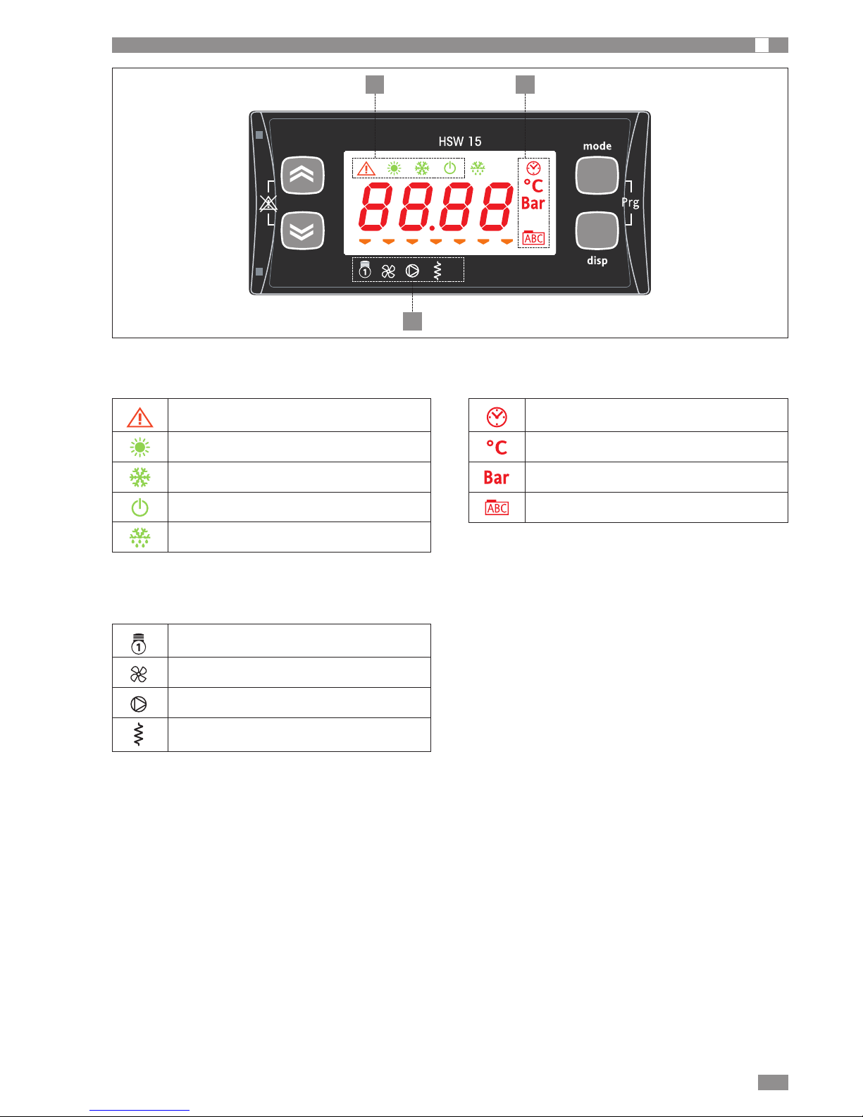
LEDS AND DISPLAY
A
Alarm
Heating
Cooling
Standby
Defrost
1 STATUS AND OPERATING MODE LEDS
Compressor
Fans
System pump
Frost protection heater system heat exchanger
3 UTILITY LEDS
Clock
Degrees centigrade
Pressure (Bar)
Menu (ABC)
2 VALUE AND UNIT OF MEASURE LEDS
set
esc
1
3
2
Page 24
BRA2 - BRN2 EN
24
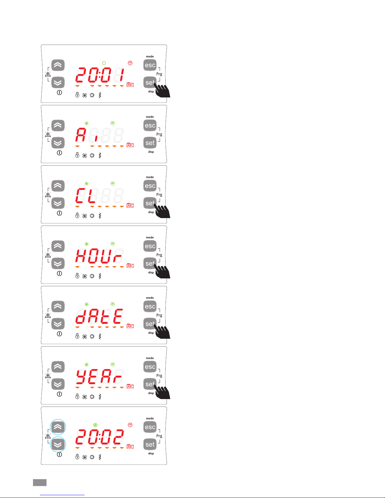
To set the clock of the unit, starting from the main display,
press the set button.
Pressing the set button once displays the various directories.
Scroll the menu using the UP and DOWN buttons until
reaching the directory CL.
SETTING THE CLOCK
The HSW15 controller is fitted with a clock for managing time bands to control specific events.
Follow the procedure shown below to set the hours, minutes and date.
To enter menu CL press the set button.
Once having entered this menu, HOUr will be shown. Select
whether to set the time, date or year using the UP and
DOWN buttons.
Once having decided which value to set, press the [set]**
button to enter the corresponding menu.
**pressed and held for 3 around seconds.
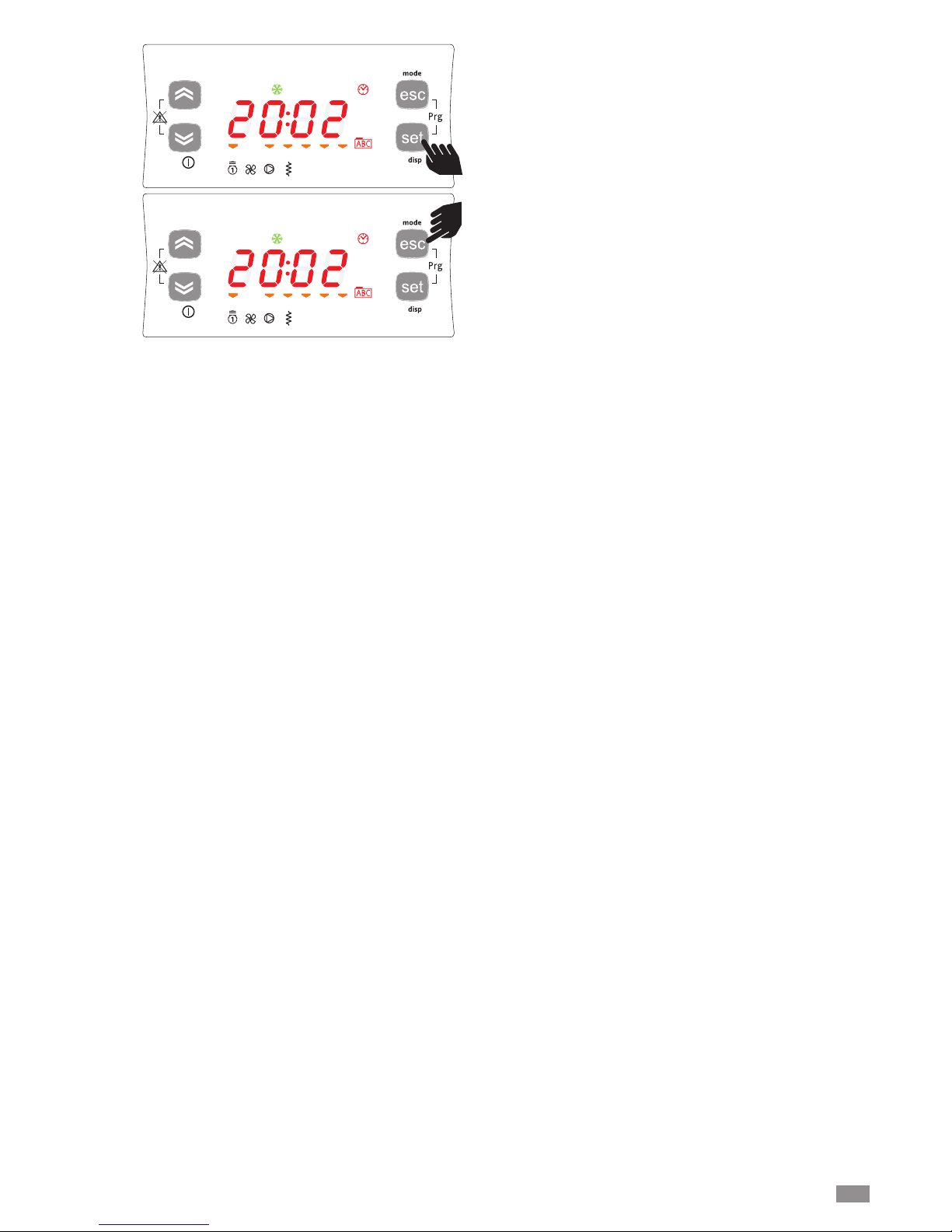
To set the time, date and year simply scroll with the UP and
DOWN buttons until the desired value and
Page 25
BRA2 - BRN2 EN
25
... press the set button.
To exit the clock setting menu press the esc button until
returning to the main display.
Page 26
26
BRA2 - BRN2 EN
SCHEDULER SETTING
The HSW15 controller can manage the unit based o the time and the day of the week.
The controller features four time bands in three profiles that can be combined, when programming, with the days of the week.
The profile defines the behaviour of the unit over a 24 hour period.
Time band management must be enabled by parameter tE00 = 1 (tE00 = 0 standard setting).
Programming example
1) Define the profile for each time band, as shown in the following table.
Description Description Profile 1 Profile 2 Profile 3
Hour / Minutes hours 00 (tE10=0) / min.00 (tE11=0) hours 00 (tE38=0) / min.00 (tE39=0) tE66..tE67
Operating mode ON/Standby ON (tE12=0) ON (tE40=0) tE68
TIME BAND 1 Cool set point tE13=15 tE42=15 tE69
Heat set point tE14=30 tE42=30 tE70
DHW set point tE15=50 tE43=50 tE71
Hour / Minutes hours 6 (tE17=6) / min.00 (tE18=0) hours 7 (tE45=6) / min.00 (tE46=0) tE73..tE74
Operating mode ON/Standby ON (tE19=0) ON (tE47=0) tE75
TIME BAND 2 Cool set point tE20=12 tE48=12 tE76
Heat set point tE21=33 tE49=33 tE77
DHW set point tE22=45 tE50=45 tE78
Hour / Minutes hours 9 (tE24=9) / min.00 (tE25=0) hours 7 (tE52=12) / min.00 (tE53=0) tE80..tE81
Operating mode ON/Standby ON (tE26=0) ON (tE54=0) tE82
TIME BAND 3 Cool set point tE27=15 tE55=12 tE83
Heat set point tE28=30 tE56=33 tE84
DHW set point tE29=50 tE57=45 tE85
Hour / Minutes hours 17 (tE31=17) / min.00 (tE32=0) hours 17 (tE59=17) / min.00 (tE60=0) tE87..tE88
Operating mode ON/Standby ON (tE33=0) ON (tE61=0) tE89
TIME BAND 4 Cool set point tE34=12 tE62=12 tE90
Heat set point tE35=33 tE63=33 tE91
DHW set point tE36=45 tE64=45 tE92
Example of profile 1 to be used
on opening days
Example of profile 2 to be used
on closing days
2) Associate one of the three programmed profiles with each day of the week.
The days of the week are identified by the parameters tE01 to tE07; tE01 = Monday, tE02= Tuesday……tE07=Sunday.
Once having displayed the day of the week, tE01 to tE07, select the value 1, 2 or 3 corresponding to Profile 1, Profile 2 and
Profile 3 respectively.
Follow the operations shown below to program the profiles and combine them with the day of the week:
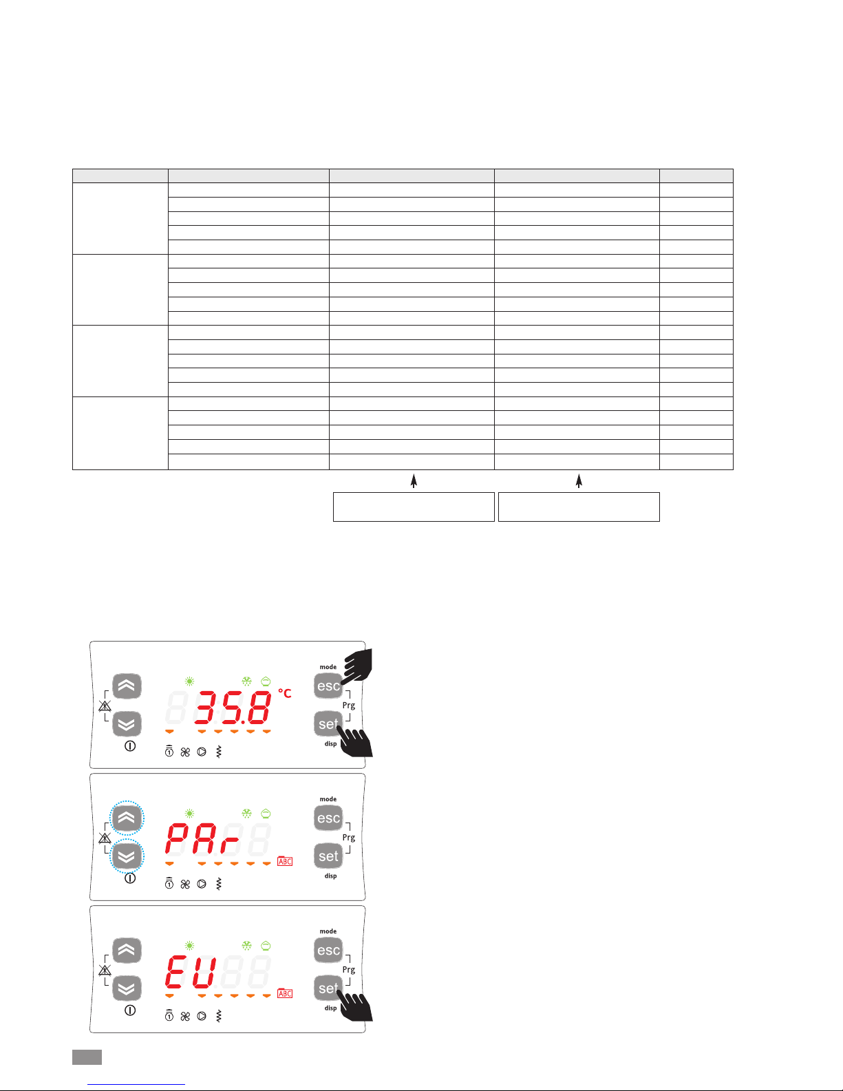
To access directory tE from the main display, press esc and
set together. [esc+set].
Pressing these two buttons enters the menu with the list of
directories.
Use the up and down buttons to scroll to the directory PAr.
Press the set button and use the up and down buttons to
scroll to the directory tE.
Press the set button to display the first parameter, tE00. Use
the up and down buttons to scroll to the other parameters.
To set the selected parameter, press the set button and
enter the value using the up and down buttons.
Confirm the changes by pressing the set button or alternatively cancel by pressing esc.
Page 27
27
BRA2 - BRN2 EN
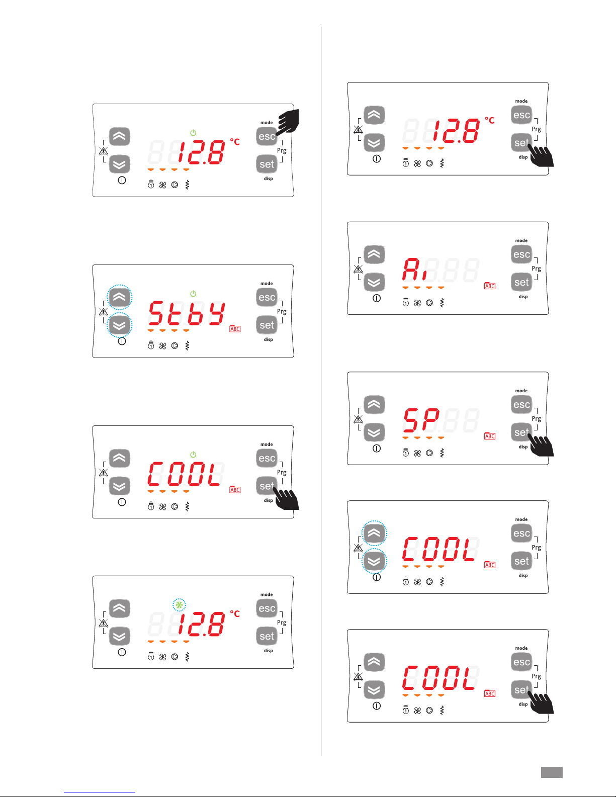
For example, to switch operation from StbY to COOL.
To change the operating mode, press and hold the mode
button for at least 2 seconds.
A scroll menu will start flashing with the values StbY (standby) and COOL (cool).
Use the up and down buttons to select the desired operating
mode.
SELECTING THE OPERATING MODE
There are three different modes:
• Standby mode (StbY)
• Cooling mode (COOL)
• Heating only mode (HEAT)
The unit will automatically return to the main display and the
Stby LED, previously on, will now be off and the COOL LED
will be on.
To change the set point, starting from the main display,
press the set button.
Pressing the set button once displays the various directories. Scroll the menu using the up and down buttons until
reaching the SP directory.
To enter the SP directory press the set button.
The active mode will be displayed (COOL).
SETTING THE SET POINTS
As an example, the Set Point in COOL mode will be
changed from 12.0 degrees centigrade to 12.5 degrees
centigrade.
Taking the example of changing the set point for the operating mode. Press the SET button.
Page 28
BRA2 - BRN2 EN
28
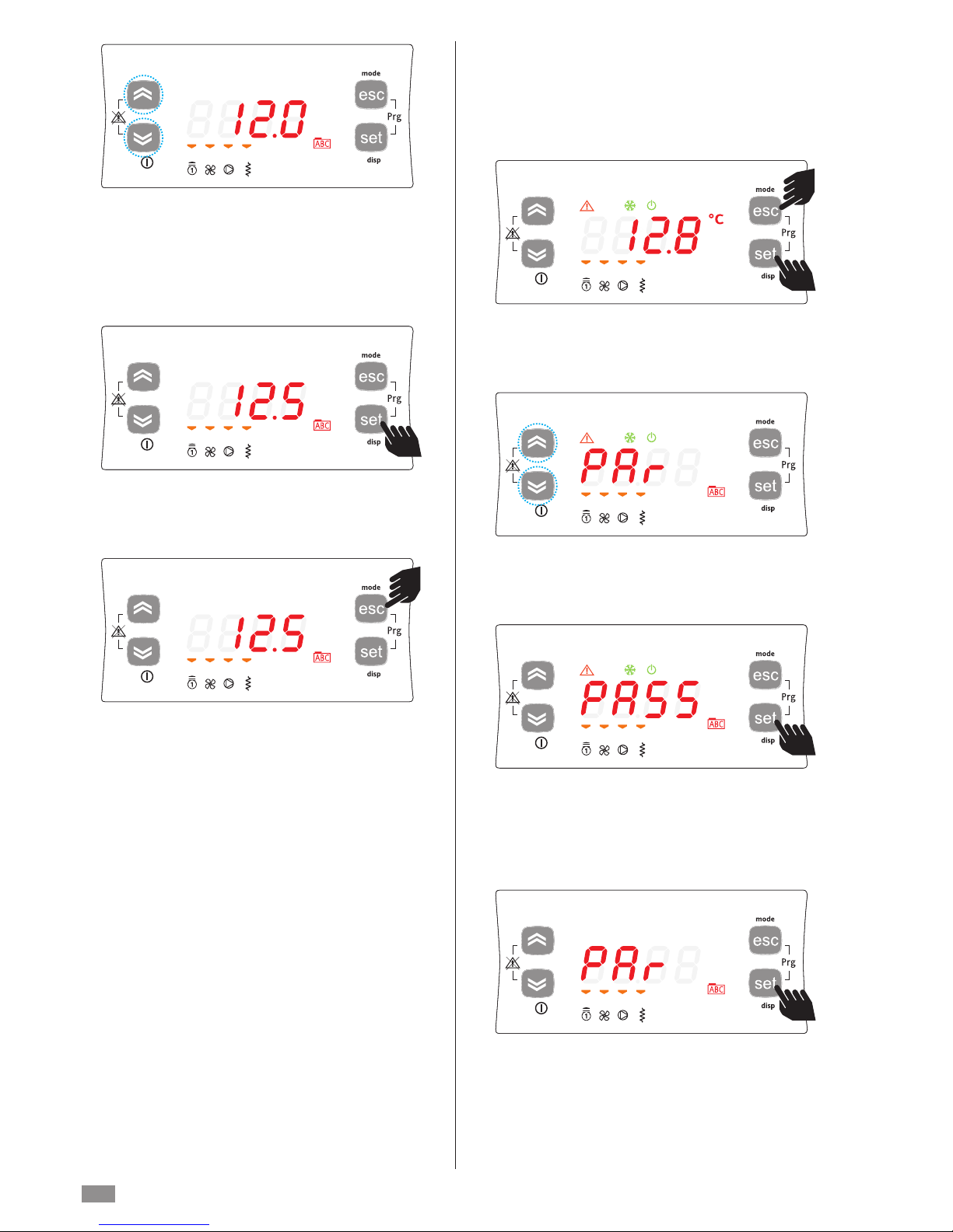
The instrument will display the current set point (in this case
12.0 degrees centigrade).
To increase or decrease the value, use the up and down
buttons.
For example, to change the set point to 12.5 degrees, press
the up button until the desired value is displayed.
Once having reached the desired set point, press the set
button. In this way, the instrument will save the value 12.5.
To return to the main display, press esc or wait for the menu
timeout to expire (15 seconds).
SETTING THE PARAMETERS
Accessing the PASS directory (from the main display, pressing the esc and set buttons together [esc+set] and scrolling
to the directory with up / down) and setting the PASS
accesses the parameters visible for the password entered.
To access the PASS directory from the main display, press
esc and set together [esc+set].
Pressing the two buttons accesses the menu listing the
directories.
Scroll using the up and down buttons to the PASS directory.
To enter the PASS directory press the set button.
Then enter the password (installer or manufacturer), press
set and exit.
Access the parameters to display or change the values.
Press the up and down buttons to select the Par submenu.
Press the set button to display the desired directory.
Page 29
BRA2 - BRN2 EN
29
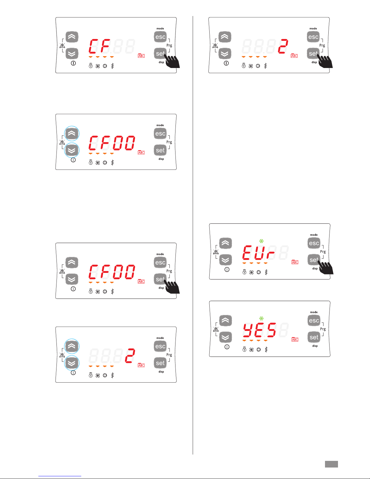
The first directory displayed by the instrument will be the CF
directory (configuration).
To set the individual CF parameters, simply press set again.
The instrument will display parameter CF00 (default factory
settings). To scroll the various parameters, simply press the
up button to go to the next parameter (in this case CF01) or
the down button to go to the previous parameter (in this
case CF47).
CF00->CF01->CF02->...->CF47->CF00
CF47<-CF00<-CF01->...<-CF46<-CF47
NOTE: -> UP, <-DOWN
To display the value of the parameter (in this case CF00),
press the set button.
For parameter CF00, the value displayed will be 2.
To change the value of the parameter, press the up or down
button.
When having selected the value, press the set button. **
To exit the display and return to the previous level, press
esc.
**NOTE: pressing the set button confirms the new value;
pressing the esc button returns to the previous level without
changing the existing value.
Press the SET button for 3 seconds.
The display shows YES, to confirm that the alarm log has
been reset.
RESETTING THE ALARM LOG (Er90)
From the main display press “esc + set”, the display will
show “Par”. Scroll using the UP and DOWN buttons until
displaying the label “FnC”. Press the SET button, the display
will show “dEF”. Scroll using the UP and DOWN buttons
until displaying “EUr”.
Page 30
BRA2 - BRN2 EN
30
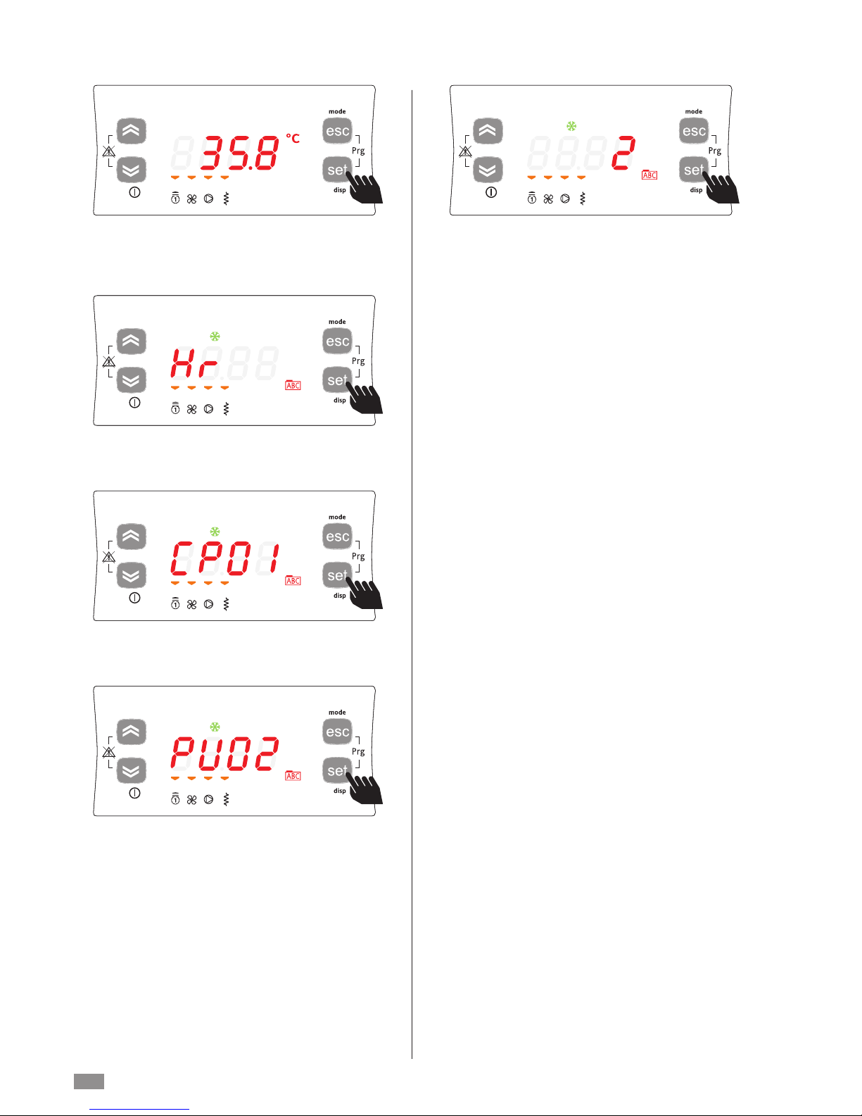
Example of displaying and resetting (tens) the Pump operating hours.
From the main display, press the set button.
The display will show label Ai. Scroll the labels using the UP
and DOWN buttons until reaching label Hr.
DISPLAYING AND RESETTING COMPRESSOR /
PUMP HOURS
Press the set button to display the first label, in this case the
operating hours for compressor 1 (CP01).
Scroll using the UP and DOWN buttons until displaying (if
featured among the resources) the operating hours for compressor 2 (CP02) and the operating hours for the pump
(PU02).
Press the set button to display the operating hours for the
pump PU02.
The tens of operating hours are equal to 2.
(The hours are expressed in tens: 2 indicates 20 operating
hours).
To reset the operating hours for the pump PU02, press and
hold [set].
Note: to reset the operating hours for the other resources,
repeat the procedure described.
To exit the menu, press esc until returning to the main
display.
Page 31
BRA2 - BRN2 EN
31
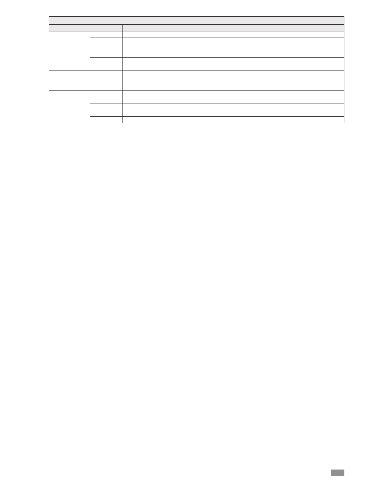
LIST OF ACCESSIBLE PARAMETERS
Directory labe
l Parameters Parameters for:
CF CF00... CF77 Configuration
Ui UI00... UI18 User interface
tr tr00... tr20 Temperature control
St St00... St04 Operating status
CP CP00... CP10 Compressor
Primary pump PI PI00... PI24 Primary water circuit pump
Fans FE FE00... FE30 Fans
Electric
HI HI00... H15 System heat exchanger electric heater
heater
dS dS00... dS07 Dynamic set point
Ad Ad00... Ad07 Adaptive
AF AF00... AF03 Frost protection
AL AL00... AL48 Alarms
CL C00... CL97 Local I/O configuration
Note 1: when setting the parameters the COMPRESSOR and HEATER LEDs will flash alternating with the DEFROST
LED.
Note 2: the above table shows a list of parameters that are all or partly available only on entering the password.
Page 32
BRA2 - BRN2 EN
32
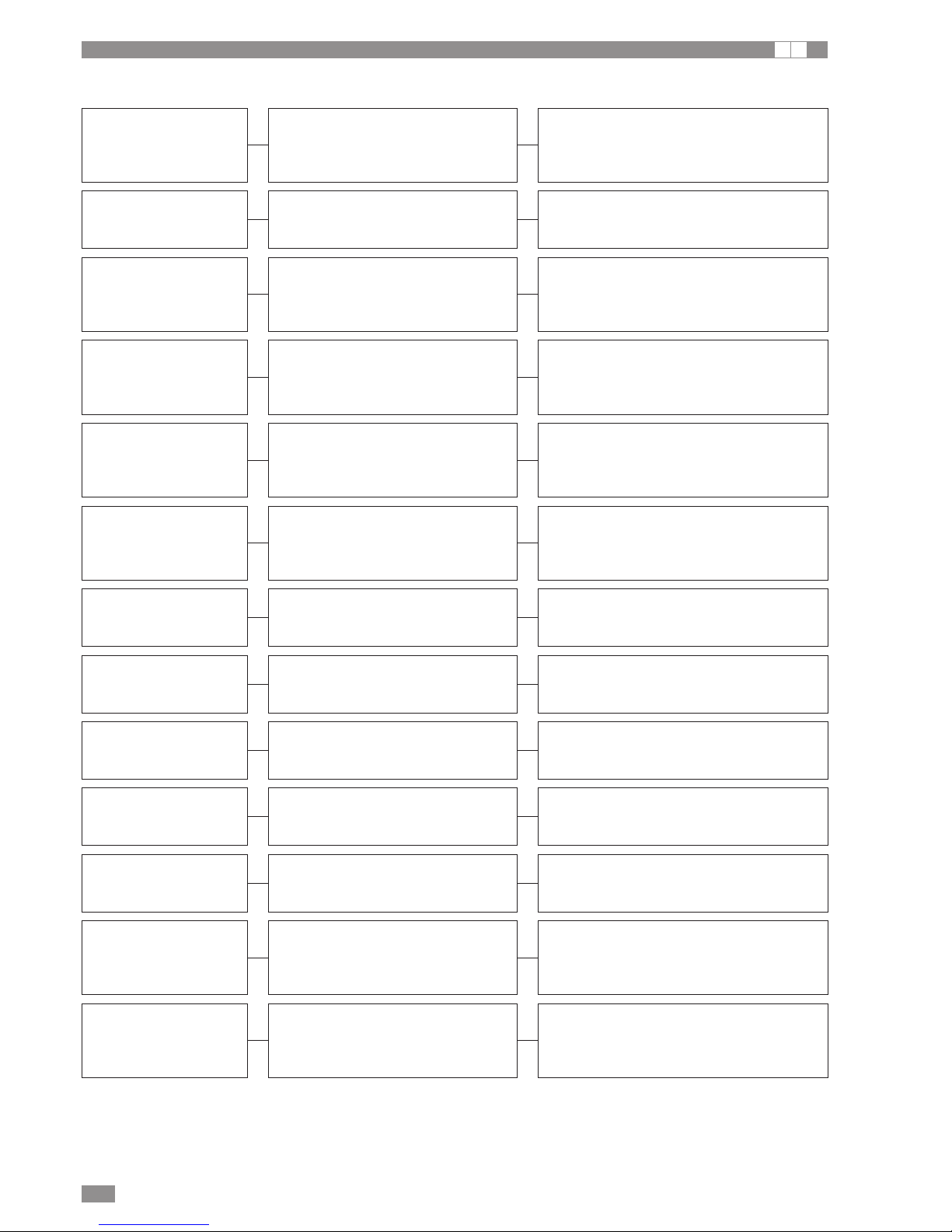
DISPLAYING ALARMS
I A
FAULT CAUSE SOLUTION
Values display indication
Er01
High pressure switch tripped, manual reset
after 3 activations in one hour, incorrect
connection of power supply phases (threephase models only)
Check fault (see high discharge pressure)
Reset manually
Change the position of two phases.
Values display indication
Er05
Low pressure switch tripped manual reset
after 4 activations per hour
Check fault
Values display indication
Er30
System frost prevention alarm (manual
reset)
Check water outlet temperature
Check water flow
Check temperature set point
Check correct positioning of sensor BT2
Values display indication
Er20
Differential pressure switch or flow switch
tripped
Manual reset if active for more than 30
seconds
Check inadequate water flow
Check for air in water circuit
Check electrical connection (see unit wiring diagram)
Values display indication
Er 10
Fan circuit breaker tripped
Manual reset if active for more than 30
seconds
Check correct sequence of power supply phases
(versions 0071-0121)
Display indication
Er47
HSW15 communication error with remote
keypad (only if remote keypad featured)
Check electrical connection
Values display indication
Er60
Faulty BT1 system water return sensor
(automatic reset)
Check electrical connections
Replace component
Display indication
Er75
Pressure transducer malfunction
Check electrical connection (see unit wiring diagrams)
Replace component
Display indication
Er81
Compressor maintenance interval
Check operating pressure
Check condition of the compressor
Reset the clock
Display indication
Er85
Water pump maintenance interval
Check condition of the water pumps
Reset the clock
Display indication
Er90
Maximum alarm log size exceeded
Reset alarm log
(paragraph "Reset alarm log")
Values display indication
Er61
Faulty BT2 system water outlet sensor
(automatic reset)
Check electrical connections
Replace component
Display indication
Er46
Set the clock
See procedure on p. 24
Page 33

33
BRA2 - BRN2 EN
PEAK LIMITER ALARM SIGNALS
I A
The heat pumps can be fitted with a single-phase or three-phase peak limiter to reduce compressor start-up current.
Single-phase peak limiter
The green LED on steady indicates line voltage is present.
The red LED identifies the type of alarm, based on the
sequence of flashes. The orange LED indicates the delay
between unit starts and/or stops.
* monitored during inactivity and bypass
** In this situation, the red LED flashes 4 times; the service
centre needs to be contacted to reset the device.
Three-phase peak limiter
The three-phase peak limiter has 2 built-in indicator LEDs.
The green LED indicates line voltage is present and correct
operation. The red LED identifies different alarm conditions
based on the sequence of flashes, as shown in the enclosed
table.
Orange LED Condition Action
ON
Minimum recovery
time between starts
and/or recovery time
between stop and start
Autoreset when the
minimum recovery
time has elapsed
Red LED Condition Action
2 flashes
Undervoltage
Ue < 190VAC)
Autoreset after
5 minutes *
3 flashes
Overcurren
(>80 A for 1 sec.)
Autoreset after
5 minutes
4 flashes Protection relay
Autoreset after
5 minutes **
5 flashes Ramp incomplete
Autoreset after
5 minutes
Green LED Condition Action
Flashing Power supply alarm
Contact service
centre
ON
Device powered,
no faults
Awaiting
compressor
start signal
Red LED Condition Action
2
Incorrect phase sequence
Reverse the phases
3
Line voltage out
of limits
Autoreset after
5 minutes
4 Frequency out of limits
Autoreset after
5 minutes
5
Locked rotor
(during ramp)
Autoreset after
5 minutes
6
Ramp starting
> 1 sec
Autoreset after
5 minutes
7 Excess temperature
Autoreset after
5 minutes
8
Low current
(during bypass)
Autoreset after
5 minutes
9 Voltage unbalanced
Autoreset after
5 minutes if all the
three phases (L1, L2,
L3) are connected
Green LED Condition Action
Flashing
1 minute recovery
between starts and/or
recovery time between
stop and start
ON
Device powered,
no faults
ON
Device powered
during ramp
Page 34

34
BRA2 - BRN2 EN
OPERATING CHARACTERISTICS
I A
Cooling set point
(factory setting) = 12°C, Hysteresis = 3°C.
The compressor starts at outlet water temperatures above
12°C+3°C (15°C).
The compressor stops at water temperatures below 12°C.
In the event of temporary power failure, when power returns,
the mode set previously will be retained in the memory.
Heating set point
(factory setting) = 40°C, Hysteresis = 3°C.
The compressor starts at water outlet temperatures below
37°C.
The compressor stops at water temperatures above 40°C.
In the event of temporary power failure, when power returns,
the mode set previously will be retained in the memory.
COMPRESSOR START-UP DELAY
Two functions prevent the compressor from starting up too
frequently.
- Minimum time since last shut-down 180 seconds.
- Minimum time since last start-up 300 seconds.
CIRCULATING PUMP
The electronic board includes a pump control output. The
pump starts when “cool” mode is activated and stops a few
seconds after “standby” mode is selected.
After the first few seconds of pump operation when the
water flow is at full speed, the water flow alarm functions are
activated (differential pressure switch and flow switch).
FAN SPEED CONTROL
To enable the unit to function correctly at different outside
temperatures, a microprocessor with pressure reading via
pressure sensor controls the fan rotation speed. This allows
the exchange of heat to be increased and/or decreased,
maintaining condensing or evaporation pressures essentially constant.
The fan operates independently of the compressor.
FROST ALARM
The frost protection function is always active, so as to prevent the water freezing and damaging the plate heat
exchanger; to do this, the microprocessor shuts down the
compressor if the temperature measured by the heat
exchanger outlet temperature sensor is less than: +4°C on
the system side.
The frost prevention temperature set point can be modified
by an authorised service centre only and only after verifying
that the water circuit contains antifreeze.
Tripping of this alarm shuts down the compressor but not the
pump, which remains active.
To reset normal functions, the water outlet temperature must
rise to more than: +7°C on the system side.
Reset is manual.
WATER FLOW ALARM
The microprocessor provides for the management of a
water flow alarm controlled by a differential pressure switch
fitted as standard on the appliance and flow switches to be
installed on the water inlet piping.
This safety device may trip after the first 60 seconds of
pump operation when the water flow is up to speed.
Tripping of this alarm shuts down the compressor but not
the pump, which remains active.
The alarm is reset automatically is it lasts less than 20 sec.
If it lasts longer, it must be reset manually.
Page 35
BRA2 - BRN2 EN
35
OPERATING CHARACTERISTICS
I A
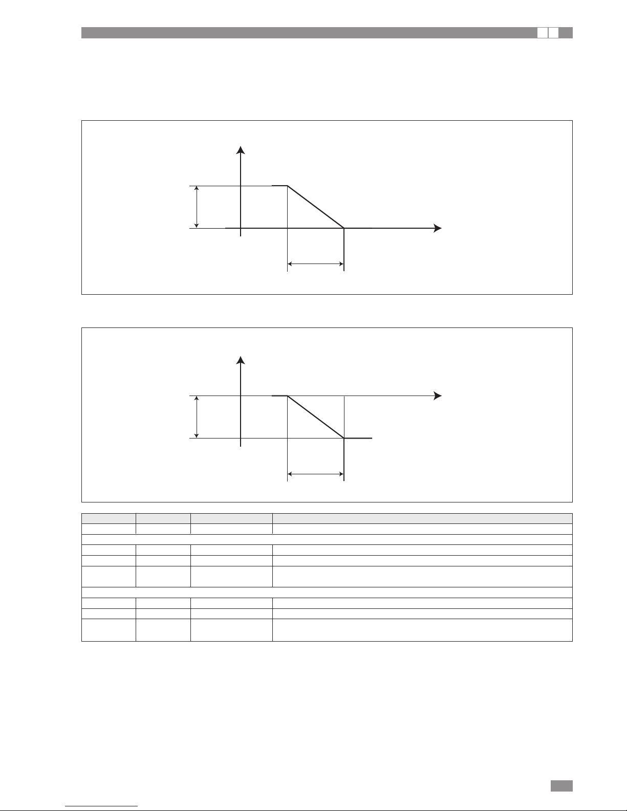
SYSTEM WATER SET POINT COMPENSATION BASED ON THE OUTSIDE TEMPERATURE
Set point compensation based on the outside temperature must be enabled by setting a parameter, see the table.
Outside air temperature probe to be purchased as an accessory, not supplied with the unit.
System water set point compensation in COOLING mode based on the outside temperature
Graph with factory settings
Outside air
temperature
Ds05 + Ds01 = 20°C Ds05 = 25°C
12°C
15°C
Water temperature set point
Ds01 = -5°C
Ds03 = 3°C
System water set point compensation in HEATING mode based on the outside temperature
Graph with factory settings
Outside air
temperature
Ds06 + Ds02 = 10°CDs06 = -5°C
28°C
33°C
Water temperature set point
Ds02 = 15°C
Ds04 = -5°C
Parameter Value Unit of measure Description
ds00 1 Enable system water set point compensation function
OPERATION IN COOLING MODE
Ds01 -5 °C Differential applied to the value of ds05
DS03 3 °C Differential applied to the system water temperature set point in cooling mode
Ds05 25 °C Outside air temperature activation/deactivation value for set point
compensation function in COOLING
OPERATION IN HEATING MODE
Ds02 15 °C Differential applied to the value of ds06
DS04 -5 °C Differential applied to the system water temperature set point in heating mode
Ds06 -5 °C Outside air temperature activation/deactivation value for set point
compensation function in HEATING
Page 36

BRA2 - BRN2 EN
36
SHUTTING DOWN FOR LONG PERIODS
A
After deactivating the chiller:
- Make sure the remote switch SA1 (if featured) is off.
- Make sure the remote keypad (if featured) shows “OFF”.
- Place QF1 in the OFF position (see wiring diagram)
- Deactivate the indoor terminal units by placing the switch
of each unit in the “OFF” position.
- Close the water valves.
If the mains switch is turned to “off” for more than four
hours, after turning it on and before reactivating the unit,
leave the power on but the unit deactivated for at least
two hours to preheat the oil in the compressor sump.
ROUTINE MAINTENANCE
A
UNSCHEDULED MAINTENANCE
A
Never perform any cleaning operations before having
disconnected the unit from the mains power supply.
Terminals 10, 11, 12, 13, 14, 15, 16, 17, 18 and 19 may be
live even when the unit has been disconnected.
Make sure power is not connected before proceeding
CHEMICAL WASHING
It is recommended to chemically flush the plate heat
exchanger after every 3 years of operation.
For instructions on how to carry out this operation, call the
toll free number.
REFRIGERANT GAS CONTENT
The chillers are charged with R-410A refrigerant gas and
tested in the factory.
In normal conditions, there should be no need for the Technical Service to intervene to check the refrigerant gas.
However, over time, small leaks may develop at the joints
leading to loss of refrigerant and draining of the circuit,
causing the unit to function poorly.
In this case, the leaks of refrigerant must be identified and
repaired and the refrigerant circuit recharged.
Proceed as follows:
- Empty and dry the entire refrigerant circuit using a vacuum
pump connected to the low and high pressure tap until the
vacuometer reads about 10 Pa.
Wait a couple of minutes and check that this value does
not rise to more than 50 Pa.
- Connect the refrigerant gas cylinder or a filling cylinder to
the low pressure line pressure gauge connection.
- Charge the quantity of refrigerant indicated on the unit’s
rating plate.
- Always check the superheat and subcooling values, which
should be between 5 and 10 °C and 4 and 8 °C.
- After a couple of hours operation, check that the liquid
indicator indicates a dry circuit (dry-green).
In the event of partial leaks, the circuit must be completely emptied before being recharged.
The R-410A refrigerant must only be charged in the liquid state.
Operating conditions other than rated conditions may
produce considerably different values.
Tightness testing or identification of leaks must only be
carried out using -R410A refrigerant gas, checking with a
suitable leak detector.
The refrigerant circuit must not be charged with a
refrigerant other than that indicated.
The use of a different refrigerant may cause serious
damage to the compressor.
Oxygen, acetylene or other flammable or poisonous gases must never be used in the refrigerant circuit as they
may cause explosion or poisoning. Oils other than those
indicated on page 16 must not be used.
The use of a different oil may cause serious damage to
the compressor.
Never perform any cleaning operations before having
disconnected the unit from the mains power supply.
Terminals 10, 11, 12, 13, 14, 15, 16, 17, 18 and 19 may be
live even when the unit has been disconnected.
Make sure power is not connected before proceeding.
Regular maintenance is fundamental to maintain the efficiency of the unit both in terms of operation and energy consumption.
The Technical Service maintenance plan must be observed,
with an annual service which includes the following operations and checks:
- Filling of the water circuit;
- Presence of air bubbles in the water circuit
- Efficiency of safety devices
- Power supply voltage
- Power consumption
- Tightness of electrical and water connections
- Condition of the compressor contactor
- Verification of operating pressure, superheat and subcooling
- Efficiency of the compressor heater
During the maintenance operations, the chiller inspection
panel may need to be removed.
If this is the case, proceed as follows:
- Open the door of the electrical panel.
- Undo the screws as shown in the figure
- Remove the inspection panel
To replace the inspection panel, repeat the procedure in
reverse.
DISPOSAL
A
The unit must be disposed of according to the legislation in force in the country concerned.
Page 37
BRA2 - BRN2 EN
37
U I A
TROUBLESHOOTING
AI
Power failure
Power supply voltage too low
Switch QF1 in OFF position
Remote switch (if featured) in OFF position
Control panel in standby
Main switch QS1 in OFF
Compressor circuit breaker OFF
Check presence of voltage
Check safety systems upstream of
the appliance
Check power line
Switch ON
Contactor coil faulty
HSW15 controller fault
Start-up capacitor faulty (if featured)
Compressor faulty
Reversed phases (three-phase units only)
Replace the component
Check
Replace the component
Check
Check
Check
Protection devices trip
and shut down the compressor
Excessive discharge pressure
Low suction pressure
Low voltage
Electrical connections not sufficiently tight
Operation outside permitted limits
Faulty operation of pressure switches
Circuit breaker tripped
Check supply voltage
Check electrical insulation of windings
Replace the component
Insufficient capacity
Insufficient refrigerant
Unit sized too small
Operation outside recommended limits
Noise and vibrations
Contact between metal bodies
RepairWeak foundations
Tighten screws
Loose screws
Compressor noisy
Liquid returning to compressor
Inadequate fastening
The unit doesn’t start
FAULT CAUSE SOLUTION
Page 38
BRA2 - BRN2 EN
38
Low suction pressure
(less than 4 bars)*
Low utility water inlet temperature
Low outside water inlet temperature
Thermostatic expansion valve faulty or blocked
Blocked water filter
Blocked plate heat exchanger
Check
Low discharge pressure
(less than 16 bars)*
Low utility water inlet temperature
Check
Air in water circuit Vent
Insufficient gas charge Check
Moisture in the refrigerant circuit (flow indicator moisture yellow)
Empty and refill
Faulty operation of outside heat exchanger control
(pressure regulating valves)
Check
High suction pressure
(greater than 20 bars)*
High utility water inlet temperature
Thermostatic expansion valve faulty or excessively
open
Check
High discharge pressure
(greater than 32 bars)*
High outside water temperature
High utility water inlet temperature
Insufficient water flow-rate in outside heat exchanger
Check
Check pump operation
Faulty operation of outside heat exchanger control
(pressure regulating valves)
Check
Air in water circuit Vent
Excessive refrigerant charge
Check
*Values indicative only
FAULT CAUSE SOLUTION
Page 39

39
BRA2 - BRN2 EN
A U
USEFUL INFORMATION
U I A
For information on technical assistance and obtaining spare parts, contact:
CLIMAVENETA S.P.A.
AFTER SALES DEPARTMENT - RESIDENTIAL BUSINESS
Via Duca d’Aosta 121 - 31031 Mignagola di Carbonera (TV) ITALY
Tel: +39.0424.509500
Fax: +39.0424.509563
www.climaveneta.com - [email protected]
Page 40
COD. C01002793C_02
 Loading...