

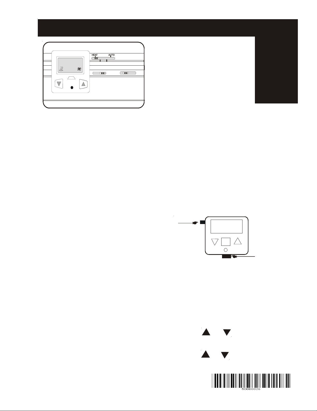
Model ATA11C04 Thermostat
Package Contents:
1 ea. Thermostat
72.5
SET
COOL
OFF
F
ONAUTO
ON AUTO LO HI
A
N
1 ea. Back Plate
1 ea. Remote Sensor Assembly
2 ea Self tapping screw 3/4” long
2 ea. W all anchors
1 ea. Instruction manual
Auto Mode
1 Stage Cool
1 Stage Heat
Model A TA1 1C04
Description:
The AT A1 1CO4 series is a digital thermostat
with modes being heat, cool and auto changeover with 2 speed fan and manual adjustment.
Specifications:
T emperature range: 32°F to 113°F
0°C to 45°C
Accuracy: ±1°F
Display: LCD
Load rating: Fan - 7 Amps; Heat/Cool 2 amps
T emperature Sampling: every 1 minute
Control range: Heat 36°F to 94°F
Cool 40°F to 98°F
Physical dimensions: 4.6 L x 2.8 W x 1.1 D
Display of Room or Set Point:
The room temperature will appear after the set point
has been displayed for 3 seconds.
T o read “set point” press “SET”.
Heat mode:
When the room temperature drops below the set
point by the number of degrees of the differential, the
heating will turn on and the icon will display . The heat
will run until the heat setting is reached, Heat icon
flashing.
Cool mode:
When the room temperature rises above the set point
by the number of degrees of the differential, the
cooling will turn on and the icon will display . The cool
will run until the cool setting is reached, cooling will
turn off and Cool icon flashing
Auto mode:
1. Move system switch to Heat mode.
Select desired temperture for Heat mode
2. Move system switch to Cool mode
Select desired temperature for Cool mode
5000-0026 Rev. b 4-2006
Auto mode cont’d.:
3. Slide system switch to Auto mode.
Example:
Heat = 68
Cool = 72
Note: make sure there is 4º dead band or
more between Heating and Cooling.
Otherwise the thermostat will automatically
push the cooling 4º below heating.
T emporary Time Delay Override:
1- Select system mode (HEA T or COOL)
2- Press Reset Button.
Reset Button is located under the display case.
ºF/ºC Jumper
SETSET
RESET BUTTON
ºF/ºC Selections:
1- Turn Power OFF
2- Jumper, Located at top left of display case.
3- Remove the Jumper for ºC selection.
Jumper ON for ºF selection.
4- Turn Power ON.
5- Press RESET if desired Measurement has
not been changed
Differential:
1- Press and together for 10
seconds.
2- Display will show 1º and Diff
3- Press or to change the
selections from .5, 1, 1.5, 2
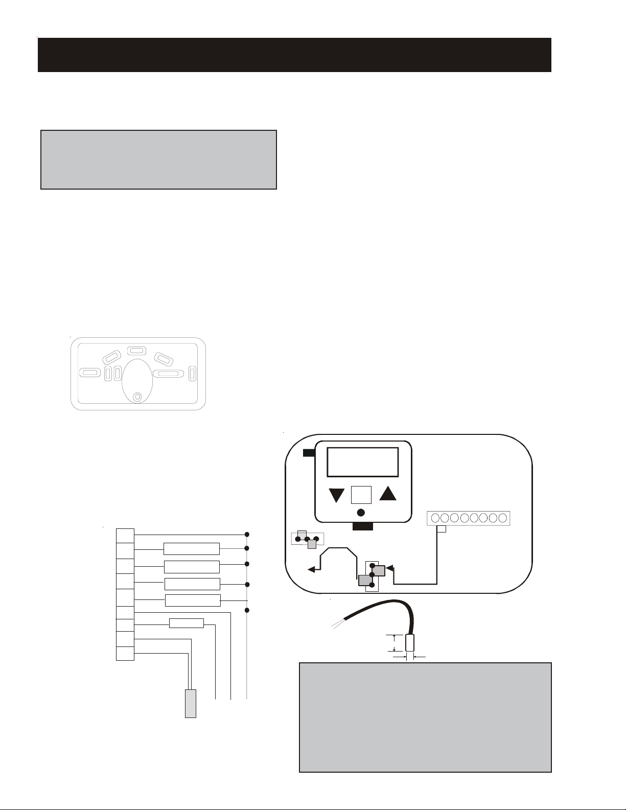
Model ATA11C04 Thermostat
Installation:
Be certain the power is turned off to the
thermostat.
All wiring and installation must conform to all
local and state codes. UL type Class II transformer must be used with 24 VAC model
thermostats.
Location:
Place the thermostat in a central location
where the family spends most of its time, such
as family or living room, etc. Do not mount
the thermostat next to any doors, on outside
walls, near drafts, HVAC supply air, etc.
1. Mount Back Plate:
Using 2 screws with anchors install Mounting
Plate.
2. Disconnect the front cover of thermostat.
a) Mount the thermostat on the mounting
plate supplied using the 2 screws.
b) Pull the wires through the wire hole and
install the wires to the terminal block. See
wiring diagram.
Testing:
1. Program the Time delay.
2. Program the Differential.
3. Slide the Switch to “Heat” raise the setting to at
least 5 °F above the room temperature. Heat icon shall
energize after time delay period. When temperatures
reaches set point heat will turn off.
4. Slide the Switch to “Cool” lower the setting by at
least 5 °F below the room temperature. Cool icon shall
energize after time delay period. When temperatures
reaches set point cool will turn off.
5. Place the fan switch to “on” and change the fan
speed. The fan switch should change speeds.
6. When common is applied to the “L” terminal the
red LED will light. Indicating that the system requires
inspection by a service contractor .
Remote Sensing:
1- Move Remote Jumper to the top 2 pins (see Fig 1).
2- Place the Remote Sensor to S1 and S1 T erminals.
Cooling And Heating Reverse Valve Selections:
1- Place The Jumper in 1 and 2 for O valve, 2 and 3
for B valve.
ºF/ºC
SETSET
S1 S1 L C R Y O/B G G2
Common
Compressor
Rev. Valve O or B
Lo Fan
Hi Fan
Lockout
C
A
V
4
2
Wiring
Diagram:
t
a
t
s
o
m
r
e
h
T
O/B
C
Y
G
G2
R
L
S1
S1
Remote Sensor
After wiring is completed place cover on the
thermostat.
5000-0026 Rev. b 4-2006
Rev. Valve Jumpers
O B
LOCAL SENSOR
RESET
Remote Jumpers
REMOTE SENSOR
Fig 1
Remote Sensor1.0
.12
Warranty:
The ATA1 1C04 series of thermostats have a limited
warranty for one year against poor workmanship, not
meeting product specifications, etc. No other liability
will be incurred other than replacing the defective
product. For complete warranty details contact factory
for a detailed warranty .
 Loading...