

Page 1
Part 5442225 issue E
General Information &
Installation Instructions
Read general information instructions first followed by
the relevant installation instructions.
3 & 4 STAR DUCTED GAS CENTRAL HEATER
ABN 13 001 418 042
26 Nylex Avenue, Salisbury, South Australia 5108 AUSTRALIA
Telephone No.: 61 8 8307 5100 Fax No.: 61 8 8283 0401
Page 2
2
Part 5442225 issue E
I
General Information
Name of appliance: Bonaire & Pyrox 3 & 4 Star Gas Central Heater
Models: MB314iNG, MB320iNG, MB330i NG, MB330i NG X/A, MB314e
NG, MB320e NG, MB330e NG,
MB414i NG, MB420i NG, MB420i NG X/A, MB430i NG, MB430i
NG X/A, MB414e NG, MB420e NG, MB430e NG, MB430e NG X/A.
Gas Consumption: 14i unit – 60MJ/h
20i unit – 80MJ/h
30i unit – 120MJ/h
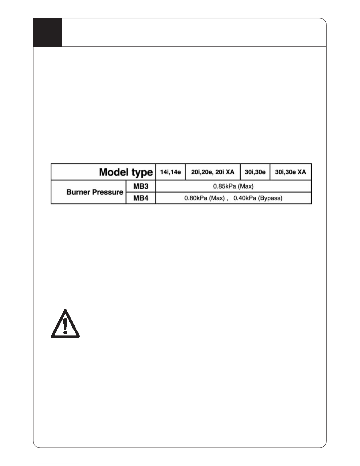
Burner Pressures:
Gas Connection: Connection on gas valve is via ¾” BSP (female) flare nut
onto which the inlet pipe and ¾” manual shut-off valve
(Refer to AS/NZS 5601) Use only gas copper pipe which
complies with AS 1432 Type B.
When connecting the gas supply inlet pipe to the gas valve, hold the
connection nipple on the valve with a spanner while tightening the inlet pipe
compression nut. This ensures the nipple is not over tightened. Cracked
gas valves or regulator castings due to over tightening during
installation or service are not the manufacturerʼs responsibility.
Statutory Requirement: This product must be installed only by
an authorised person and in accordance with the current editions
AS/NZS 5601 & AS/NZS 3000.
DO NOT OPERATE THIS APPLIANCE BEFORE READING THIS
GENERAL INFORMATION & INSTALLATION BOOKLET.
Checking Supply & Burner Pressures:
Refer to data plate on the product for burner pressures.
NOTE: All wiring coming out of the unit (mains power lead, thermostat
wiring etc…) must be fully extended and securely anchored using the cable
tie provided.
Page 3

3
Part 5442225 issue E
General Information (cont)
I
Items to be supplied by the Installer:
- Suitable base material for heater.
- Platform/Walkway for roof installation (heat resistant material not required).
- Electric lighting above the central heater and switch to be placed next to
the access opening.
- AGA approved manual shut-off valve (3/4” Natural Gas Heater).
- AGA approved metal flue pipe and required elbows where a flue pipe with
bends is present. AGA approved flue cowl for the flue pipe.
- At the completion of the installation compliance certificates must be
completed for gas & electrical work.
Locations:
1) Do not install the heater in a location where combustible vapours from
flammable or combustible liquids may be present as these can be drawn
into the heater and ignited.
2) Do not install the heater in any location where noise from its operation
may disturb occupants or neighbours. Before installing this product
consider placement of this unit away from areas of the home where
occupants will sleep or relax, such as bedrooms, lounge and dining
rooms. Check local council regulations to ensure compliance.
3) Do not install the heater downstream of an evaporative air conditioner, air
washer or refrigeration coil.
DESCRIPTION OF OPERATION OF ELECTRONIC CONTROL MODULE.
The design of the control module conforms to the Australia Gas Association
AS4622 and AS4625 Standards and is classified as a Class 2Ca device. It
receives instructions via a wired or RF Controller/thermostat.
Electrical rating:
240V, 50 Hz, 10 VA input.
Start up sequence for Central Heater:
1) Turn gas supply on.
2) Turn on power supply to unit.
3) A 2-second self-diagnosis is performed and the fans will run for a few
seconds. If a successful diagnosis is completed the unit will then go to
stand-by mode.
NOTE: Where Navigator RF thermostat is used this must be configured (paired)
with the transceiver before the unit can be operated refer to section 7.
4) To start unit set the thermostat temperature above the room temperature.
5) Combustion air fan will commence operation.
Page 4
4
Part 5442225 issue E
General Information (cont)
I
6) When combustion fan reaches required pressure level, the pressure
switch closes.
7) A further 20 seconds elapses as purge time.
8) Igniter function commences.
9) Gas valve is energised allowing 4 seconds for the gas to ignite.
10) If flame is detected by a sensor. The gas valve remains energised.
11) Room air fan will commence 20 seconds after the gas valve is
energised.
12) At the end of the heating cycle, the room air fan will have a run down
period of 80-180 seconds.
13) Should the flame not ignite after the 6th attempt, the unit will go to
lockout. Reset unit to restart.
14) To reset the unit, switch the mains power OFF then wait 2 seconds
before switching the power back ON or with the navigator control a
error code is displayed when a lockout has occurred. When the word
“enter” appears in the display press the enter key to reset the unit.
CHECKING THE SYSTEM PERFORMANCE
Having set the gas pressure check the discharge temperature of the air in
the discharge duct to confirm the correct operation of the central heater.
For best performance, the discharge temperature should be 50C – 60C
when measured 300mm from the appliance inside the discharge air duct.
Checking the correct operation of the heater:
1) Using the thermostat, switch the heater OFF. Wait for the room air fan
to cease operation (approximately 80 -180 seconds), then switch ON
again to recheck the starting sequence.
2) Using the thermostat, switch the heater OFF unless the customer
requires that it be left running.
3) Before leaving, make sure that the customer understands how to
operate the heating system.
4 Star (MB4XXX) product will not operate unless the
thermistor has been connected and the sensor installed
correctly in the air discharge duct.
Page 5

5
Part 5442225 issue E
General Information (cont)
I
Special Conditions:
Blocked fresh air inlet or flue outlet:
The unit will go to lockout. ʻWhen the restriction is removed the unit can then
be reset.
NOTE: If the fresh air inlet, the flue outlet is blocked or combustion fan is not
operating correctly the red LED on the controller may not light-up. If this
occurs, the unit will not commence the ignition sequence and will then lockout.
The green LED will then flash the appropriate fault code.
Electric power loss:
3 star units – The unit will restart automatically if the manual
controller/thermostat is ON, once power is resumed.
4 star units – if a manual controller/thermostat is left switched ON, the unit
will automatically lock-out when power is resumed. The reset procedure must
then be followed to restart the unit. Once power is resumed.
Gas interruption:
A gas interruption will cause the unit to lockout. The Controller/thermostat
must be reset after gas supply is re-established.
Controller diagnostic LED flash codes:
The controller will flash a coded message if an operation fault occurs.
For 3 star product refer to the table listed on the appliance data plate for
further details. For 4 star product refer to page 11-13 of this book or the
service manual.
Normal Operation:
3 star units – Green LED will flash a single short flash (approximately 0.2
seconds/pulse) when in the idle state and flash one short pulse when calling
for heat. Red LED will light-up when combustion fan is operating correctly.
4 star units – Green LED will flash four short pulses (approximately 0.2
seconds/pulse) when in the idle state and flash one short pulse when calling
for heat. Red LED will light-up when combustion fan is operating correctly.
Trouble Shooting:
• Check there is power and gas supplied to the heater.
• Check thermostat set temperature is above room temperature.
• Confirm thermistor is connected correctly installed in the air discharge
duct. (4 star models only)
• Check that the power LED is lit on the controller. If it isnʼt check power is
available at the GPO, check the circuit breaker and check the fuses on
electrical panel within the unit.
• If the heater will still not operate, the safety shut down device within the
heater may have locked the control. Reset the control.
• If the heater still fails to operate correctly, contact service.
• For Service Australia Wide see the contact details on the rear cover.
Page 6
6
Part 5442225 issue E
1
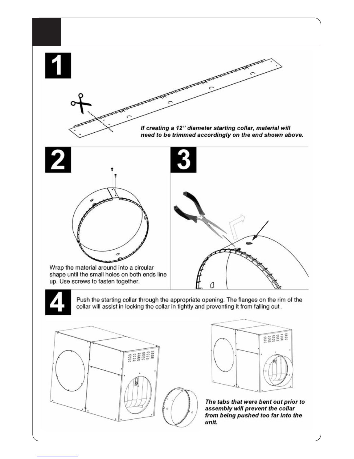
Starting Collars
Starting collars are manufactured from pre-painted or
galvanised steel and supplied as a flat part
Use pliers to bend the four stop tabs
out. Be sure to bend them out to at
least a 90 angle.
Four ducting
retention hooks
are provided to
assist with fixing
duct to collar.
Page 7
7
Part 5442225 issue E
2
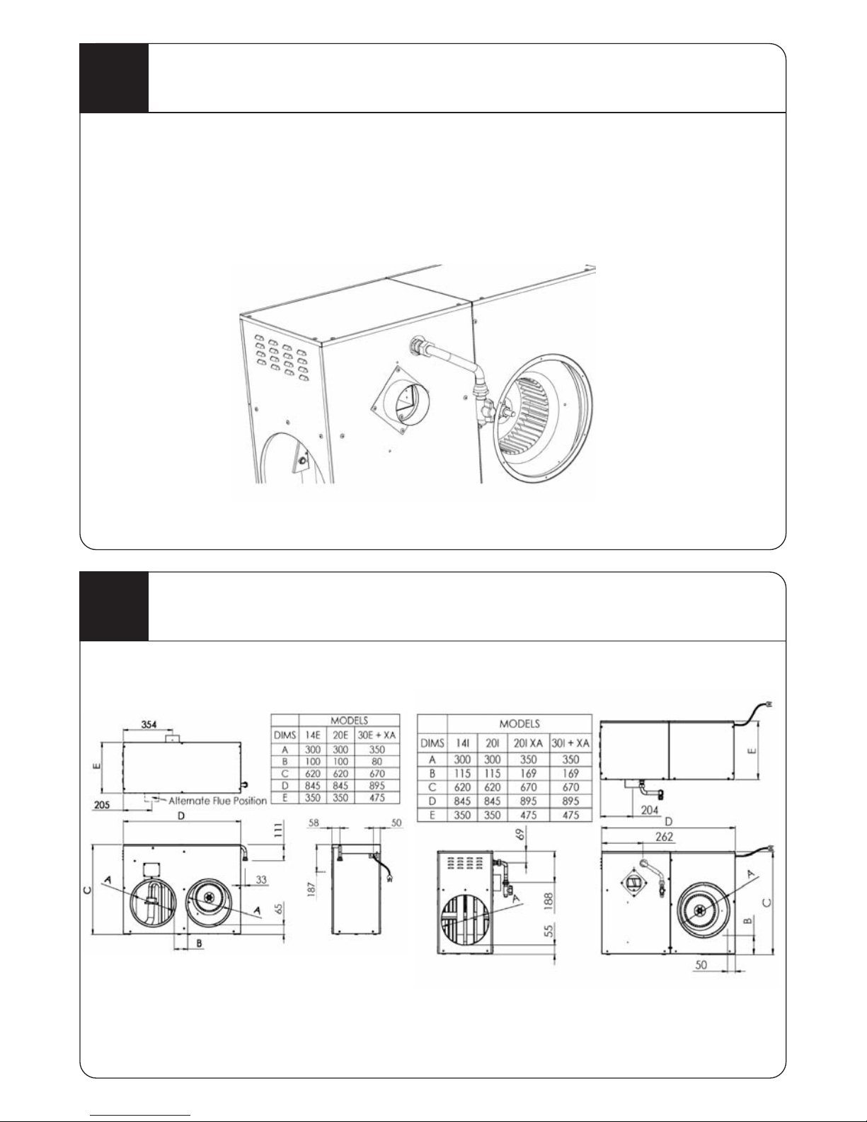
Gas supply and manual shut-off valve
3
Product Dimensions
All gas piping must comply with AS/NZS 5601. Piping must be correctly sized to
suit product supply requirements and ensure a minimum supply pressure of
1.13kpa (natural gas). The maximum gas consumption for this product can be
found on the product label affixed to the unit. An AGA approved manual shut-off
valve must be installed in the gas supply line for this unit. The valve should be
installed in a suitable location adjacent to the unit which will ensure easy access
for service.
Once an A.G.A approved manual shut-off valve is fitted it may be positioned
horizontally or vertically subject to location of heater and ease of access.
External products Internal products
Page 8
8
Part 5442225 issue E
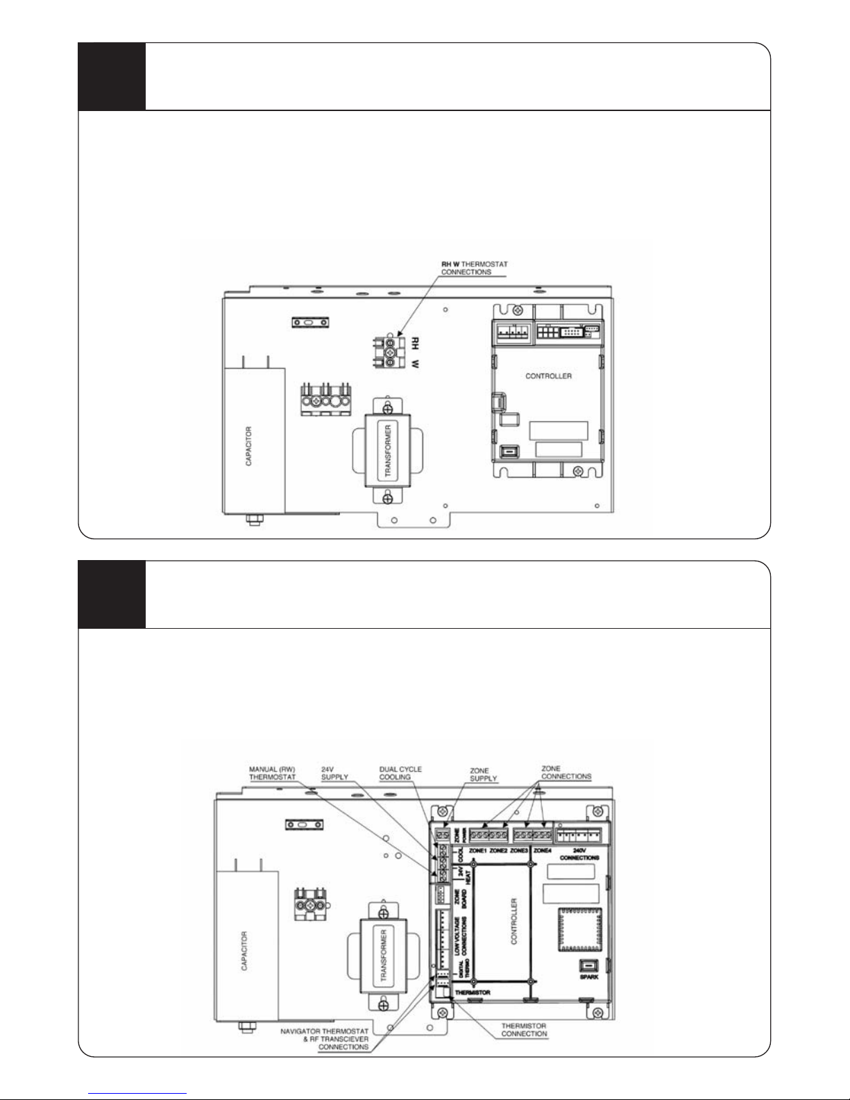
5
4 Star Thermostat Connection
4
3 Star Thermostat Connection
For manual thermostat installation and wiring connection information, refer to
instruction sheet supplied with the thermostat.
For navigator thermostat control installation refer to the navigator user manual.
Where a 2 wire manual thermostat is used the connecting wiring used must have a
minimum cross sectional area of 0.75mm or greater.
For manual thermostat installation and wiring connection information refer to
instruction sheet supplied with thermostat.
For navigator thermostat control installation refer to the navigator user manual.
Where a 2 wire manual thermostat is used connecting wiring used must have a
minimum cross sectional area of 0.75mm or greater.
Page 9
9
Part 5442225 issue E
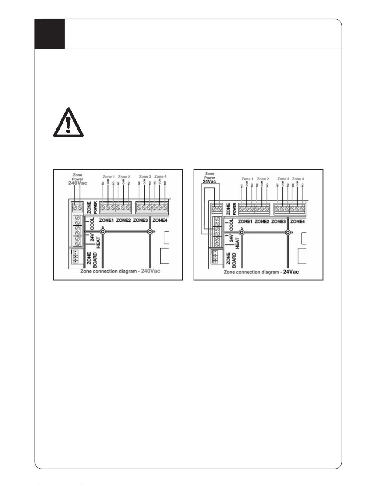
6
4 Star Zone Connection and Dual Cycle cooling
The control module in every 4 star heater has integrated zone outputs.
This control has four relay switched outputs for connection of zone dampers.
The control will manage zone outputs in accordance with commands sent by the
Navigator thermostat. Zone control can be expanded from four to eight if required
by purchasing an expansion card and a connection cable.
The installer is responsible for all electrical cabling and sizing and
compliance with AS/NZS 3000 (latest edition).
Zone Power Supply:
Zone power can be taken from the 24VAC supply on the control by connecting as
shown below or from an external supply.
Zone Output Connections:
Depending on the desired configuration each zone output has a common (COM)
connection and a normally open (NO) or normally closed (NC) as shown. Connect
either to NC or NO as required.
Enabling Zone Control:
To activate zone control and zone expansion board installation parameters must
be enabled. Refer to the Navigator digital thermostat user manual for instructions.
For each zone required, the control parameter number must be set for the total
number of zones required (e.g. for “4” zones set parameter to “4”).
NOTE: For zone expansion board installation, refer to instructions supplied with
expansion board kit.
Dual Cycle Cooling:
The control has available a 24 volt only connection for installations where a
refrigerated cooling coil is installed. To activate this function a installation
parameter must be enabled using the Navigator thermostat (refer to Navigator
thermostat user manual).
NOTE: For cooler connection details, refer to installation instructions supplied with
the cooler.
Page 10

10
Part 5442225 issue E
7
Installation of Navigator Controller
BEFORE STARTING
Before attempting to use the setup instructions for the controls system, make sure the
transceiver (remote control units only) or the wired low voltage cable is connected,
batteries have been correctly installed in the Navigator Controller (remote control units)
and the 240 volt power has been turned on to the product.
NOTE: Do not run the low voltage loom in long parallel runs with 240V mains
cables. Keep the low voltage loom 200mm away from any long runs of mains
wiring. Cross over mains wiring at right angles. Do not use existing access holes
in wall cavities where 240V mains wiring exist. Drill a new access hole 200mm
from the existing hole.
INSTALLATION
Where the control is using the thermostat for operation, it
must be installed approximately 1.5 metres above the floor
level on a room wall which is most commonly used for best
average sensing.
Secure the Navigator Controller cradle to the wall using the
screws and plugs provided.
• For hard wired versions drill an access hole through the
cradle to bring the cable into the control. Once
connected snap the control into the cradle.
• For the remote Navigator Controller (wireless) install
batteries and slide the Navigator Control into the cradle.
The Navigator Controller should remain in the cradle
during normal operating conditions for optimum
temperature thermostat control.
Do not locate Navigator Controller near concealed hot or
cold water pipes, warm air ducts, radiators, sunlight,
televisions or draughts from hallways, stairways and
fireplaces or external walls. These can all affect the
temperature.
Remote Control Units ONLY
Ensure the transceiver has been installed at least 500 mm clear of all metal masses. The
transmissions between the remote Navigator Controller (wireless) and the unit control
box are radio signals which are subject to interference. The primary causes for signal
interference are:
• Metal Construction buildings or metal masses near the antenna.
• Incorrect location of the antenna
• Cordless RF door bells
• Other Faulty appliances
• Navigator Controller too close to computers
• Powerful radio scanners
Page 11

11
Part 5442225 issue E
8
Installation of Navigator Controller
(cont)
INSTALLATION OF TRANSCEIVER
The transceiver cable connects to the control box as
shown.
Fully extend the transceiver cable (4 meters) and attach
the transceiver housing to a solid surface such as a rafter
or vertical column using the two screws provided. Avoid
direct contact with metal surfaces. Connect the
transceiver plug to one of the two thermostat connections
on the control box.
When the installation is complete and the power to the
heater is turned on, a green LED in the transceiver case
should be visible confirming it is connected correctly and
is ready for pairing with a Navigator controller.
To ensure trouble free operation, the transceiver
housing & connecting cable should not be installed
within 200mm of any power cables or other radio
transmitting devices. The transceiver housing should
be placed 1m away from any metal object.
Do not screw the transceiver to the back of the
control box; it must be run into roof space.
PAIRING THE NAVIGATOR CONTROLLER (Remote Only)
The BONAIRE Navigator Controller and transceiver does
not have any pairing information when they are delivered
from the factory.
On the first power up, the transceiver will request to PAir
with Navigator Controller for period of a 30 min window
and its green light will be illuminated. If it does not PAir
within that time, it will PAir on the next power up. Put the
Navigator Control in pairing mode -
1. Press & hold the ENTER button for 3 seconds.
2. Press the Heat/Cool, Mode & Setup buttons in
sequence. The display will flash “PAir”.
3. After a few seconds the Navigator Controller displays
the “ro XX” (“XX” is the unique serial number. For
example “ro 22”). It will also display the strength of the
signal.
4. Press the ENTER button to pair the transceiver and the
Navigator Controller.
NOTE: Wait until the backlight turns off and press
any key after 2 minutes.
5. Press the ON/OFF button to go to the main display.
RF Transceiver & cable
assembly
Page 12
12
Part 5442225 issue E
9
Multiple Navigator Controller 9 Operation
OPERATION OF MULTIPLE NAVIGATOR CONTROLLERS
The Navigator control system is capable of supporting up
to 4 controllers. By default, the system will allow one
controller to control the appliance or multiple appliances.
Certain parameter set ups must be made to configure
multiple controllers.
The options available are
• 2 wired Navigators only
• 1 wired Navigator and up to 3 Remote Navigators.
MULTIPLE WIRELESS REMOTE CONTROLLERS
In a multiple Navigator controller system, the other
controller may be joined to a master by putting the slave
controller into a PAir mode. It will then send out a PAir
request to the master controller. The master controller is
then put in a JOin state and can then join the request to
set up a Navigator system.
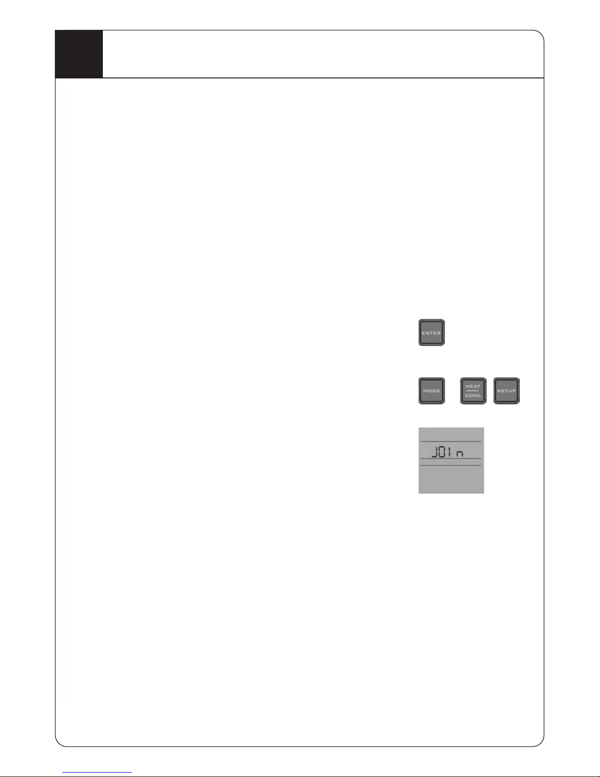
JOINING NAVIGATOR CONTROLLERS (JO
IN
)
Controllers requesting to JOIn another controller in the
Navigator system, can be put in the join mode as follows.
1. To enter the JOIn state, press and hold the ENTER
button for 3 seconds & release.
2. Press and release the, MODE, HEAT/COOL and
SETUP buttons in sequence.
3. The master wireless Remote controller should display
JOin state to receive a command from the other
handset to JOIn the Navigator system.
4. The slave controller should be placed into a Pair state
to join with the master controller. The slave controller
should display Pair.
Page 13
13
Part 5442225 issue E
10
Accessing Navigator Controller Installer Setups
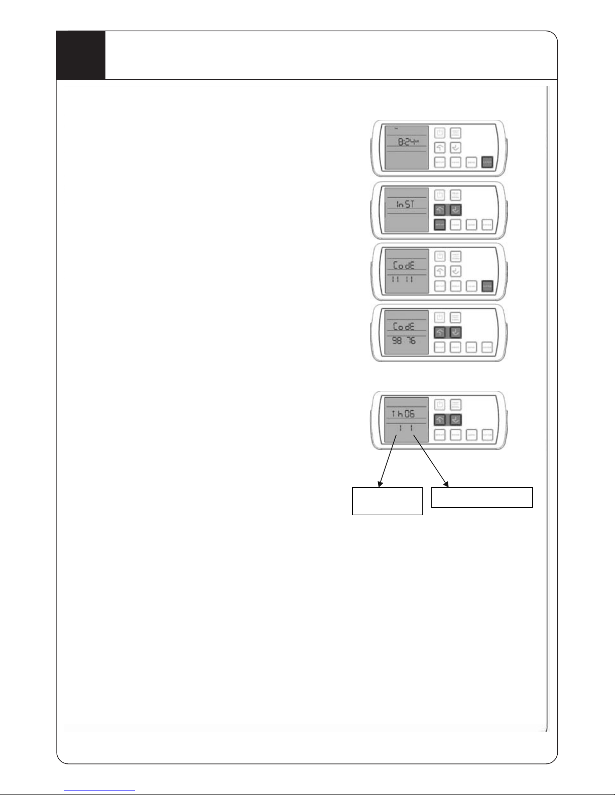
NOTE: The Navigator Controller must be in the OFF
status to change the parameters.
1. Press and hold the ENTER button for 3 seconds.
2. Press & release the Ï then Ð then SETUP
buttons to enter the installer set up mode.
3. The word “InST”, ”nSTA”, ”STAL”, ”TALL”,
”ALLE”, ”LLEr” (Installer) scrolls across the upper
part of the display. Press the ENTER button.
4. When the CodE “11 11” appears, input the code
“98 76” using the Ï and Ð buttons to select each
digit, and press the ENTER button to move to the
next digit
NOTE: The Navigator Controller will display
the abbreviated name of the
appliance such as “EC XX” for
Evaporative Cooler, “HE XX” for
Central Heater or “th XX” for the
Navigator controller settings (“XX” is
the unique serial number). For
example “th 06”.
5. Use the Ï and Ð buttons to scroll to the “th XX”
and then press the ENTER button to access
Navigator Installer setup.
The display will now show digits “1 1”. The lower left
digit is the parameter number and the lower right digit
is the parameter option value. Parameter numbers
and option values can be found in the Navigator
Controller Installer Parameters Table.
6. To select the parameter number use the Ï and Ð
buttons to find the desired parameter and press
ENTER.
7. Adjust the option value (See Navigator Parameter
Table) to the required value and press ENTER.
This will set the option value and return you to the
parameter number selection menu.
8.
When finished Press the ON/OFF button to exit.
Parameter
Options value
Page 14
14
Part 5442225 issue E
11
Navigator Controller Parameters Table
th parameter Table (“th XX”)
Parameter Description Default Definition Options Values
1
Un switched
Zone Option
1
Tells system if
there is a common
zone present
1= common zone
present.
0= no common zone
(Note that a cooler is
usually installed into the
common zone)
2
Switched
Zones
15
To display all
available switched
zones
15= Zone 1, 2,3 & 4
6 = Zone 2&3
127 = 8
Using ZONE and ÐÏ
buttons whilst in this
parameter will set the
number
3
Temperature
Display zone
0
Selects which zone
the Navigator will
display the
temperature of
0 –Common zone
1-8 Zones 1-8
4
Temperature
Measurement
-Un switched
Zone option
1
Determines if the
navigator is
measuring the
temperature in the
common zone
1Measuring common
zone.
0= Not measuring
common zone
5
Temperature
Measurement
- Switched
Zones
15
Determines which
of the switched
zones the
Navigator is
measuring,
15= Zone 1, 2,3 & 4
6 = Zone 2&3
127 = 8
Using ZONE and ÐÏ
buttons whilst in this
parameter will set the
number
6
Not used
0
7 Not used
8
RF Network
(RF handset
only)
0
The current RF
network number
0 = not assigned
Any other = actual
network
0
Not used
0
Page 15
15
Part 5442225 issue E
12
Accessing Ducted Gas Central Heater (DGCH) Installer Setup
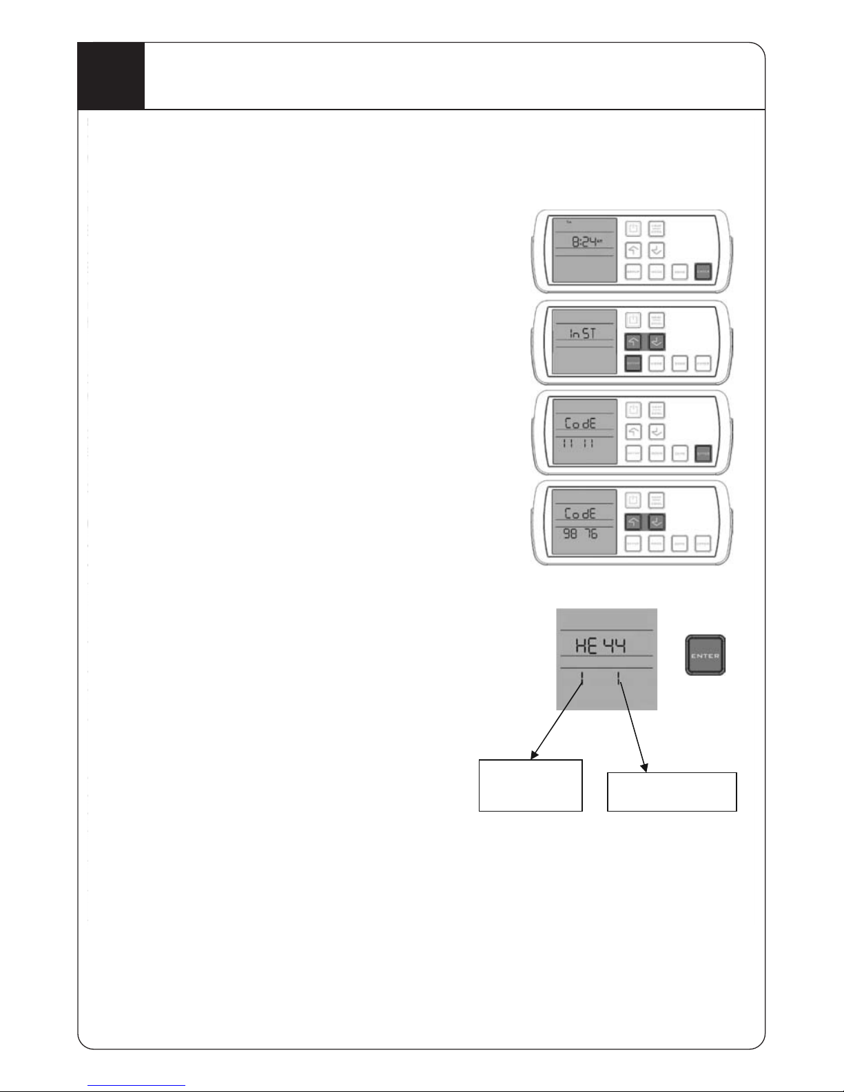
NOTE: The Navigator Controller must be in the
OFF status to change the parameters.
(Except Fan Speed)
1. Press and hold the ENTER button for 3 seconds.
2. Press & release the Ï then Ð then SETUP
buttons to enter the installer set up mode.
3. The word “InST”, ”nSTA”, ”STAL”, ”TALL”, ”ALLE”,
”LLEr”(Installer) will scroll across the upper part of
the display. Press the ENTER button now to
access.
4. When the CodE “11 11” appears, input the code
“98 76” using the Ï or Ð buttons to change each
digit, and press the ENTER button to move on to
the next digit.
NOTE: The Navigator Controller will display
the appliance controller ID “HE XX” for
a central heater (“XX” is the unique ID
number).For example “HE 44”.
5. Press the ENTER button when “HE XX” appears.
The display will now show digits “1 1”. The lower
left digit is the parameter number and the lower
right digit is the parameter option value.
Parameter numbers and option values can be
found in the Ducted Gas Central Heater Installer
Parameters Table.
6. To select the parameter number use the Ï or Ð
buttons to find the desired parameter and press
ENTER.
7. Adjust the option value (See DGCH parameter
table) to the required value and press ENTER.
This will set the option value and return you to the
parameter number selection menu.
8. When finished press the ON/OFF button to exit.
Parameter
Number
Options Value
Page 16

16
Part 5442225 issue E
13
Ducted Gas Central Heater (DGCH) Installer Parameter Table
HE Parameter Table (“HE XX”)
Parameter Description Default Definition Options Values
1
Un switched Zone
Option
1
To allow for a
common zone
and all zones to
be switched off if
necessary
1= Allows all zones
to be switched off.
0= Does not allow all
zones to be
switched off
2
Switched Zones
15
To display all
available
switched zones
0=No switched
zones.
15= Zone 1, 2,3 & 4
6 = Zone 2&3
127 = 8
Using ZONE and
ÐÏ buttons whilst in
this parameter will
set the number
3
Cool Enable
0
Enables the
control board to
drive refrigerated
cooling
0=Off – Not driving
Refrig cooling (Dual
Cycle)
1=On – Allowing
Refrig cooling to
operate.
4
Room fan speed
minimum
12
Low modulated
fan speed
Range 3 - 25
5
Room fan speed
maximum
30
Maximum fan
speed
Range 10 - 31
6
Zone 1 Weight
8
Air flow capacity
required for zone
Range 1 - 16
7
Zone 2 Weight
8
Air flow capacity
required for zone
Range 1 - 16
8
Zone 3 weight
8
Air flow capacity
required for zone
Range 1 - 16
9
Zone 4 Weight
8
Air flow capacity
required for zone
Range 1 - 16
10
Zone 5 Weight
8
Air flow capacity
required for zone
Range 1 - 16
11
Zone 6 Weight
8
Air flow capacity
required for zone
Range 1 - 16
12
Zone 7 Weight
8
Air flow capacity
required for zone
Range 1 - 16
13
Zone 8 Weight
8
Air flow capacity
required for zone
Range 1 - 16
14
Zone Common
Weight
16
Air flow capacity
required for zone
Range 1 - 16
15 Not used
0 Not used 0
Page 17

17
Part 5442225 issue E
14
Zones Setup
Unswitched Zones- (Common Zone)
The system is capable of operating a common (or unswitched) zone allowing all
other zones to be turned off.
In the unswitched zone parameter, set the parameters required according to HE
parameter table.
1 – Allows all other zones to be switched off
0 – Will not allow all zones to be turned off and one must always be on.
Switched Zones
The system is capable of controlling up to 8 switchable zones. The number of zones
shown in the display is set from parameter 2 in the Ducted Gas Central Heater
Installer Parameter table. The Navigator Controller needs to have parameter 2
changed to 127, this will display all zones on the controller.
DGCH INSTALLER SETUP PARAMETERS (Example)
Single heater- No zone dampers, common zone only
Parameter Id Value Meaning
Unswitched Zones 1 1 common zone enabled
Switched Zones 2 0 no switched zones
Single Heater - 2 zone dampers
Parameter Id Value Meaning
Switched Zones 2 3 Zones 1 & 2 installed
Single Heater - 4 zone dampers
Do nothing
. Default controller parameters are set for 4 zones and no common zone.
ADDING ZONES
1. Enter the Installer Navigator Controller set up parameters.
2. Proceed to parameter 2 and press ENTER.
3. Set the value to 127 and press ENTER.
4. Exit this setup by pressing ON/OFF.
5. Enter the Ducted Gas Central Heater Installer parameter setup.
6. Press the ZONE button to toggle on or off the zones you require (indicated by the
S under the zone number).
7. Press the Ï or Ð buttons to move to the next zone.
8. Press the ENTER button to select.
MULTIPLE CONTROLLERS – SHARED ZONES
Single DGCH with individual zones and multiple Navigator controllers
For multiple Navigator controllers, the best results require one Navigator measuring
the temperature in zones 1 & 2, the other measuring zones 3 & 4. None should
measure the common zone. This assumes that the Navigators are physically
installed in Zones 1 and 3 respectively
Page 18

18
Part 5442225 issue E
14
Zones Setup
(cont)
Navigator 1 Thermostat Installer Parameters
Parameter Id Value Meaning
Temperature Display Zone 3 1 Displaying temperature in zone 1
Temperature Measurement –
Common Zone
4 0 No measurement from common zone
Temperature Measurement –
Switched Zones
5 3 Measuring zones 1 & 2
Navigator 2 Thermostat Installer Parameters
Parameter Id Value Meaning
Temperature Display Zone 3 3 Displaying temperature in zone 3
Temperature Measurement –
Common Zone
4 0 No measurement from common zone
Temperature Measurement –
Switched Zones
5 12 Measuring zones 3 & 4
NOTE: There is no difference in setup between a wall mounted wired and wireless
remote Navigator installation.
LTIPLE CONTROLLERS – INDIVIDUAL ZONES (Example)
This feature allows each controller on the navigator system to be assigned to a zone
or a group of zones that is not assigned to any other controller on the system. In this
configuration, there is no interaction between controllers. Each has complete
independent control over its zones and the program set on that control is unique to
that controller and zone. In this mode, you will NOT assign any controller to the
common or unswitched zone.
To enable this feature, Multiple Controllers in individual zones, the system
configuration parameter must be set to 3 (Individual) on all controllers. Best results
will be achieved when one Navigator controller is assigned to zones 1 & 2, the other
to zones 3 & 4. The common zone must be disabled. This assumes that the
Navigators are physically installed in Zones 1 and 3 respectively.
Navigator 1 Controller Installer Parameters
Parameter Id Value Meaning
Unswitched Zone 1 0 Common zone disabled
Switched Zones 2 3 Controlling Zones 1 & 2
Temperature Display Zone 3 1 Displaying temperature in zone 1
Temperature Measurement –
Common Zone
4 0 No measurement from common zone
Temperature Measurement –
Switched Zones
5 3 Measuring zones 1 & 2
Navigator 2 Controller Installer Parameters
Parameter Id Value Meaning
Unswitched Zone 1 0 Common zone disabled
Switched Zones 2 12 Controlling Zones 3 & 4
Temperature Display Zone 3 3 Displaying temperature in zone 3
Temperature Measurement –
Common Zone
4 0 No measurement from common zone
Temperature Measurement –
Switched Zones
5 12 Measuring zones 3 & 4
MULTIPLE CONTROLLERS – INDIVIDUAL ZONES (Example)
Page 19

19
Part 5442225 issue E
14
Zones Setup
(cont)
NOTE: There is no difference in setup between a wall mounted wired and wireless
remote Navigator installation.
MULTIPLE NAVIGATOR CONTROLLERS – UPSTAIRS DOWNSTAIRS CONFIGURATION
This feature allows two Navigator Controllers to be used to control an installation with
a common zone downstairs and one or more damper controlled zones upstairs. Both
Navigators have equal control over the system and the last change made on one
Navigator will be copied to the other Navigator to keep the system in synchronisation.
(Note that with remote thermostats, the change may take some minutes to appear on
the second Navigator while they are in the “sleep” state. The heater will respond
immediately to any change).
To enable this feature for a two damper installation,
1. Pair the common zone (downstairs) Navigator Controller.(Remote only)
2. Join the upstairs zone Navigator Controller to the common zone
controller.(Remote only)
3. Set the parameters as per the following table,
Navigator 1 Controller Installer Parameters
Parameter Id Value Meaning
Unswitched(common) Zone 1 1 Common zone present
Switched Zones 2 3 Zones 1 & 2 available
Temperature Display Zone 3 0 Displaying temperature in common
zone
Temperature Measurement –
Common Zone
4 1 Measurement from common zone
Temperature Measurement –
Switched Zones
5 0 Not Measuring other zones
Navigator 2 Controller Installer Parameters
Parameter Id Value Meaning
Unswitched (common) Zone 1 1 Common zone present
Switched Zones 2 3 Zones 1 & 2 available
Temperature Display Zone 3 1 Displaying temperature in zone 1
Temperature Measurement –
Common Zone
4 0 No measurement from common zone
Temperature Measurement –
Switched Zones
5 3 Measuring zones 1 & 2
Heater Installer Parameters
Parameter Id Value Meaning
Unswitched (common) Zone 1 1 Common zone present
Switched Zones 2 3 Zones 1 & 2 available
Page 20

20
Part 5442225 issue E
14
Zones Setup
(cont)
ZONE WEIGHTING
The Navigator controller supports 8 switched zones and 1 common zone. Each zone
(switched and common) will have a “weighting” (air flow balance) associated with the
zone to define the fan speed for that zone.
The “weightings” are stored in the DGCH installer set up parameters and may be
altered to suit the load of each zone or the balance of the air for that zone. The table
below outlines the defaults and setting options. The zone weighting only applies to
heating and fan, Dual Cycle refrigerated cooling will default to maximum air flow and
zones should be set accordingly.
To understand zone weighting, is to simply understand that a total zoned duct system
irrespective of how many zones must equal the number 32.
Each switched zoned area must have a number between 4 & 16. The table below
shows the default numbers for zones.
If the common zone facility is turned on in the Navigator controller to allow all
available zones to be switched off, the common zone will have a number 16.
If the common zone facility is not turned on and there are 4 switchable zones, each
zone will have the number of 8.
Parameter Description Default Range
6 Weight Zone 1 8 1-16
7 Weight Zone 2 8 1-16
8 Weight Zone 3 8 1-16
9 Weight Zone 4 8 1-16
10 Weight Zone 5 8 1-16
11 Weight Zone 6 8 1-16
12 Weight Zone 7 8 1-16
13 Weight Zone 8 8 1-16
14 Weight Zone Common 16 1-16
To Decrease the air flow of the zoned area adjust the number value down.
To Increase the air flow to a zoned area, adjust the number value up
Example below of a typical 3 switched zone system that has a common zone
enabled.
Therefore If…
Living area (The common area) 16
Bedroom 4
Meals Kitchen 8
Study 4
Total of the zoned system 32
If it is found that the bedrooms do not have enough air and Meals Kitchens has too
much air the following changes would be made to the zone weight numbers.
Living area (The common area) 16
Bedrooms 5
Meals Kitchen 7
Study 4
Total of the zoned system 32
Page 21

21
Part 5442225 issue E
15
Wiring Diagram 3 Star
16
Wiring Diagram 4 Star
24/240Vac
Fault Code LED
Page 22

17
Fault Codes 4 Star
22
Part 5442225 issue E
LEDʼs and Status flash codes
The Red LED indicates the combustion fan is operating correctly and the pressure
switches have activated which then allows the ignition sequence to commence.
The Green LED will display the status of the heater controller. The LED flashes will be
of different duration times & patterns to indicate controller status.
LED patterns are divided into groups to aid the troubleshooting. Presence of LONG
pulse always indicates that the unit is in a lockout. The number of long pulses in an
LED pattern indicates the category of the lockout and the number of the following
short pulses in an LED pattern points to
the actual cause of a lockout.
Short pulses only indicate normal operation and non-lockout events or status.
1 LONG pulse followed by short pulses:
Lockouts caused by external switches and sensors (i.e.; thermistor, over temperature
switch, pressure switch or flame sensor).
2 LONG pulses followed by short pulses:
Lockouts caused by the controller hardware or by ignition, main valve, or modulation
valve.
3 LONG pulses followed by short pulses:
Lockouts caused by safe start faults or ground connection faults.
NOTE: 3 star status flash codes can be found on the product label.
Page 23

23
Part 5442225 issue E
18
Fault Codes 4 Star (cont)
Page 24

24
Part 5442225 issue E
19
Fault Codes 4 Star (cont)
20
Service Access
IMPORTANT: For service the nearest obstruction above the top of the unit must be 30mm or greater
for internal units and 300mm or greater for external units.
Page 25

25
Part 5442225 issue E
21
Commissioning Check List
GENERAL
All equipment ordered by the customer is installed.
The unit is level and secure.
The mains and control wiring are complete, the circuit breaker and GPO are
turned ON.
All Controller functions for the appliance operate.
All electrical or gas connections are to manufacturer’s specifications and the
relevant electrical or gas standards and codes.
DUCTED EVAPORATIVE AIR CONDITIONER UNIT
The water supply line has been flushed to clear swarf and debris and is free of
leaks.
The tank is free of foreign matter and debris and the water isolating tap is
turned ON.
Water drainpipe work is completed and sealed.
The water basin fills with water and the float valve closes correctly when the
water level is 65-70mm below the overflow level.
The water pump operates correctly when turned ON at the controller.
The Dialflo water bleed rate is adjusted to suit local water conditions – if
required.
The tank drains correctly when unit turns off.
The fan deck is correctly located and the fan blade spins freely.
The fan operates through the entire speed range.
The minimum & maximum fan speeds is correctly set.
Water distribution is even with the filter pads fitted and the air conditioner
operating pump and fan.
DUCTED CENTRAL HEATING UNIT
Electrical polarity of the power outlet is correct.
Heater is installed away from sources of dust and fumes (i.e. pool
chlorine/petrol etc).
Checked for gas leaks, none present.
Flue outlet pipe complies with limits given / code and is sealed waterproof.
Page 26

26
Part 5442225 issue E
21
Commissioning Check List
(cont)
Combustion air meets requirements (internal, under floor).
Fan speed settings are correct.
Burner pressure is correct.
Mounting pad/platform complies with requirements / codes.
Internal unit access platforms & service light fitted and complies with codes.
DUAL CYCLE REFRIGERATED AIR CONDITIONING UNIT
Unit Foundation correct and Condenser unit is level
Leak test performed
System vacuumed down
Condenser service valves opened.
System is charged with additional charge as required
All clearances around the condenser set to manufacturer’s specifications.
DUCTWORK
All ductwork is completed to plan, correctly supported and airtight, with no bend
less than 1.5 x the ductwork diameter.
Air distribution checked, dampers are adjusted and all outlets correctly adjusted
and wiped clean.
All roof penetrations are fully sealed and watertight.
Service access cover replaced.
SITE
All rubbish has been removed from inside and on the roof.
CUSTOMER HAND OVER
The following has been explained to the customer –
The operation of the Controller.
The need to open windows and doors for the correct operation of Ducted
Evaporative Air Conditioning
The operation of the bleed or dumping system and it’s importance to operate all
the time while ducted Evaporative cooling is in use.
Maintenance requirements
Page 27

27
Part 5442225 issue E
I
NOTES
Page 28

Part 5442225 issue E
Installation Instructions
Roof Installation
Read general information instructions first followed by
the relevant installation instructions.
Installation must comply with the current editions of
AS/NZS 5601 and AS/NZS 3000.
Page 29

29
1
Location of heater
Part 5442225 issue E
Roof Installation
2
Roof Space
Roof Installation
Consideration should be given to the placement of heater away from
sleeping and living areas of the home. Areas above the laundry, garage or
bathrooms may provide the lowest noise impact to the home environment.
Installation in a roof space must comply with the current editions of AS/NZS 5601.
Walkways and platforms must be installed and capable of supporting the
combined weight of the heater and persons accessing the heater, isolating gas
valve or power switch.
DO NOT install the heater in a location where cooking, grease of other flammable
vapours may be drawn into the heater and ignited.
The heater platform should be installed in a location where noise will not easily
be transmitted into sleeping or resting areas of the home.
Page 30

30
Part 5442225 issue E
3
Lighting & Power
Roof Installation
Roof space must have adequate lighting so as to provide enough illumination on
the walkway as well as the serviceable areas of the heater. This unit requires a
10AMP GPO power supply within 600mm of the unit.
Page 31

31
Part 5442225 issue E
4
Splitting the unit (OPTIONAL)
Roof Installation
In the event that the assembled unit
will not fit through a designated roof
access point for installation all internal
products can be split into two parts.
Each half of the unit can then be
passed through the roof access point.
Reassemble the two halves after they
are placed in a suitable location.
Lift off top panel.
Remove two screws “X” at the top above electrics
panel and disconnect ignition wire “Z”.
Disconnect harness connectors.
Lift the fan box off the hooks and the two halves can now be separated. Reassemble in
reverse order. Ensure the fan box is correctly engaged on both hooks before screwing the
two halves back together.
X
XX
Z
Page 32

32
Part 5442225 issue E
5
Flue Installation
Roof Installation
All flue materials not supplied with this product and used in its installation must be
AGA approved.
This heater must be flued using Ø100mm (minimum) metal flue pipe.
Any flue pipe sections which are not accessible for inspection shall be twin walled
or stainless steel.
Total flue length shall not exceed 6 metres and have no more than two 90 bends.
All flue pipe connections and joins must be sealed with approved materials to
comply with AS5601.
All flue configurations must comply with AS/NZS 5601 and local building codes.
6
Duct Configurations Suitable duct configurations to suit installation needs
Roof Installation
Page 33

33
Part 5442225 issue E
7
Ducts & Fittings
Roof Installation
Do not squash ductwork to fit through
an opening, as airflow will be
restricted. Find a better location.
If more than 6m of flexible ductwork is
required in one length, the next
available size flexible duct must be
used.
Return Air Grille
Locate the return air grille in a central heated area. Where a zoned installation is
planned ensure the return air grille is located in a common zone which cannot be
isolated.
Supply Air Duct to have 2-3m straight section before any bends or Y junctions.
4 star units install the thermistor into the discharge air duct
between two and three metres from the outlet of the unit.
Ductwork should be sized to suit the heater and installation to
prevent excessive back pressure.
Page 34

34
Installation Instructions
Under Floor Installation
Read general information instructions first followed by
the relevant installation instructions.
Part 5442225 issue E
Installation must comply with the current editions of
AS/NZS 5601 and AS/NZS 3000.
Page 35

35
Part 5442225 issue E
1
Water / Drainage Provisions
2
Spacing and Clearances
Under Floor Installation
Under Floor Installation
Page 36

36
3
Spacing and Clearances
4
Obstructions
Part 5442225 issue E
Under Floor Installation
Under Floor Installation
Page 37

37
Part 5442225 issue E
5
Lighting
6
Power Outlet
Under Floor Installation
Under Floor Installation
Page 38

38
Part 5442225 issue E
8
Wall Cover Plate
Under Floor Installation
7
Flue Installation
Under Floor Installation
All flue materials not supplied with this product and used in its installation must be
AGA approved.
This heater must be flued using Ø100mm (minimum) metal flue pipe.
Any flue pipe sections which are not accessible for inspection shall be twin walled
or stainless steel.
Total flue length shall not exceed 6 metres and have no more than two 90 bends.
All flue pipe connections and joins must be sealed with approved materials to
comply with AS/NZS 5601.
All flue configurations must comply withAS/NZS 5601 and local building codes.
Page 39

39
Part 5442225 issue E
9
Duct Configurations Suitable duct configurations to suit installation needs
Under Floor Installation
4 Star units install the thermistor into the discharge air duct
between two & three metres from the oulet of the unit.
Page 40

40
10
Duct & Fittings
Part 5442225 issue E
Under Floor Installation
Do not squash ductwork to fit through
an opening, as airflow will be
restricted. Find a better location.
If more than 6m of flexible ductwork is
required in one length, the next
available size flexible duct must be
used.
Return Air Grille
Locate the return air grille in a central heated area. Where a zoned installation is
planned ensure the return air grille is located in a common zone which cannot be
isolated.
Supply Air Duct to have 2-3m straight section before any bends or Y junctions.
4 star units install the thermistor into the discharge air duct
between two and three metres from the outlet of the unit.
Ductwork should be sized to suit the heater and installation to
prevent excessive back pressure.
Page 41

Installation Instructions
External Installation
Read general information instructions first followed by
the relevant installation instructions.
41
Part 5442225 issue E
Installation must comply with the current editions of
AS/NZS 5601 and AS/NZS 3000.
Page 42

42
Part 5442225 issue E
2
Clearances and Distances
External Installation
1
Unit Location
External Installation
Page 43

43
Part 5442225 issue E
3
Ground Surface Provisions
External Installation
4
External Installation
Wall Opening Clearances and Distances
Spirit level
Concrete or brick base
Page 44

44
Part 5442225 issue E
5
Wall Preparations
External Installation
6
External Installation
Wall Preparation Distancing
Page 45

45
Part 5442225 issue E
7
GPO and Distance
External Installation
8
Ducts and Fittings
External Installation
4 Star units install the thermistor into the discharge air duct between two &
three metres from the oulet of the unit. Air inlet and outlet on external units
can be changed to opposite side to suit installation needs.
If the inlet/outlet configuration is changed it may be necessary to also swap the
outlet position for the combustion fan. See instruction in section 9.
NOTE: 4 Star units also have an internal cover on the
heat exchanger side which must also be removed &
fitted to other side if the covers are being
GPO and all electrical wiring must comply with AS/NZS 3000.
Ensure service cord is properly secured and protected from mechanical damage.
Page 46

46
Part 5442225 issue E
10
Combustion Fan Repositioning
External Installation
9
Flue Spigot Assembly
External Installation
If an alternative flue cowl is used this must be AGA approved.
NOTE: THE FLUE COWL MUST BE SECURELY ATTACHED
TO THE UNIT WITH THE SCREWS PROVIDED.
Page 47

I
NOTES
47
Part 5442225 issue E
Page 48

Part 5442225 issue E
Manufactured by
Climate Technologies
ABN 13 001 418 042
26 Nylex Avenue
Salisbury, SA 5108
Australia
www.climatetechnologies.com.au
“Excelling today for a better tomorrow”
FOR SERVICE:
Tas, Vic: (03) 8795 2456
ACT, NSW, NT, Qld, SA: 1300 665 087
Mobile Callers all states: (03) 8795 2460
Victoria: vicservice@climtech.com.au
South Australia: saservice@climtech.com.au
New South Wales & Queensland: nswservice@climtech.com.au
Western Australia: waservice@climtech.com.au
 Loading...