

ClimateMaster TSL Series, Tranquility Vertical Stack Series, TSL09, TSL12, TSL18 Installation Operation & Maintenance
...
Tranquility®Vertical Stack
(TSL)
Series
Commercial
Vertical Stack
Water-Source Heat Pumps
Installation, Operation
& Maintenance
97B0127N01
Rev.: April 24, 2019
Table of Contents
General Information 3
TSL Model Nomenclature - Cabinet 4
TSL Hybrid Nomenclature - Cabinet 5
Heat Pump Cabinet Slot Dimensions and Riser
Arrangements 6
E Cabinet Slot Dimensions and Riser Arrangements 7
TSL Model Nomenclature - Chassis 8
Accessory Nomenclature 9
Pre-Installation Information 11
Riser Installation 12-15
Cabinet Installation 16-22
Water-Loop Heat Pump Applications 23
Ground-Loop Heat Pump Applications 24
Ground-Water Heat Pump Applications 25
Water Quality Standards 26
Electrical Wiring - Line Voltage 27
Electrical Wiring - Low Voltage 28
Blower Performance Data 29-36
Thermostat Installation 37
Chassis Pre-Installation 38
Hose Kit & Chassis Installation 39-41
Start-Up Preparation 42
CXM Control 43
DXM2 Control 44
Safety Features - CXM/DXM2 Controls 46
Unit Commissioning and Operating Conditions 48
Unit and System Checkout 49
Unit Start-Up Procedures 50
Unit Operating Pressures and Temperatures 51-53
Coax Water Pressure Drop 54
Hybrid Unit CorrectionTables 54
Start-Up Log Sheet 55
Preventive Maintenance 56
Functional Troubleshooting 57
Performance Troubleshooting 58
Harness Part Numbers 59-65
Troubleshooting Form 66
Warranty 67
Revision History 68

CLIMATEMASTER WATER-SOURCE HEAT PUMPS
TSL Vertical Stack
Rev.: 04/24/2019
This Page Intentionally Left Blank
2
ClimateMaster Water-Source Heat Pumps

THE SMART SOLUTION FOR ENERGY EFFICIENCY
Safety
Warnings, cautions, and notices appear throughout this
manual. Read these items carefully before attempting any
installation, service, or troubleshooting of the equipment.
Vertical Stack
Rev.: 04/24/2019
General Information - Inspection
CAUTION: Indicates a potentially hazardous situation or
an unsafe practice, which if not avoided could result in
minor or moderate injury or product or property damage.
DANGER: Indicates an immediate hazardous situation,
which if not avoided will result in death or serious injury.
DANGER labels on unit access panels must be observed.
WARNING: Indicates a potentially hazardous situation,
which if not avoided could result in death or serious injury .
WARNING!
WARNING! Verify refrigerant type before proceeding.
Units are shipped with R-407c and HFC-410A (EarthPure®)
refrigerants. The unit label will indicate which refrigerant is
provided. The EarthPure® Application and Service Manual
should be read and understood before attempting to service
refrigerant circuits with R-407c or HFC-410A.
WARNING!
WARNING! To avoid the release of refrigerant into the
atmosphere, the refrigerant circuit of this unit must be
serviced only by technicians who meet local, state, and
federal profi ciency requirements.
WARNING!
WARNING! The installation of water-source heat pumps and
all associated components, parts, and accessories which
make up the installation shall be in accordance with the
regulations of ALL authorities having jurisdiction and MUST
conform to all applicable codes. It is the responsibility of
the installing contractor to determine and comply with ALL
applicable codes and regulations.
Dimensions ar e inch es ( m m ).
NOTICE: Notifi cation of installation, operation, or
maintenance information, which is important, but which is
not hazard-related.
WARNING!
WARNING! All refrigerant discharged from this unit must
be recovered WITHOUT EXCEPTION. Technicians must
follow industry accepted guidelines and all local, state, and
federal statutes for the recovery and disposal of refrigerants.
If a compressor is removed from this unit, refrigerant circuit
oil will remain in the compressor. To avoid leakage of
compressor oil, refrigerant lines of the compressor must be
sealed after it is removed.
CAUTION!
CAUTION! To avoid equipment damage, DO NOT use
these units as a source of heating or cooling during the
construction process. The mechanical components and fi lters
will quickly become clogged with construction dirt and debris,
which may cause system damage.
WARNING!
WARNING! Polyolester Oil, commonly known as POE oil, is
a synthetic oil used in many refrigeration systems including
those with HFC-410A refrigerant. POE oil, if it ever comes
in contact with PVC or CPVC piping, may cause failure of
the PVC/CPVC. PVC/CPVC piping should never be used
as supply or return water piping with water source heat
pump products containing HFC-410A as system failures and
property damage may result.
Inspection -
check the shipment against the bill of lading. See fi gure 1
for components. Make sure all units have been received.
Inspect the packaging of each unit, and inspect each unit
for damage. Ensure that the carrier makes proper notation
of any shortages or damage on all copies of the freight
bill and completes a common carrier inspection report.
Concealed damage not discovered during unloading
must be reported to the carrier within 15 days of receipt of
shipment. If not fi led within 15 days, the freight company
can deny the claim without recourse. Note: It is the
responsibility of the purchaser to fi le all necessary claims
with the carrier. Notify your equipment supplier of all
damage within fi fteen (15) days of shipment.
Upon receipt of the equipment, carefully
climatemaster.com
3
CLIMATEMASTER WATER-SOURCE HEAT PUMPS
TSL Vertical Stack
Rev.: 04/24/2019
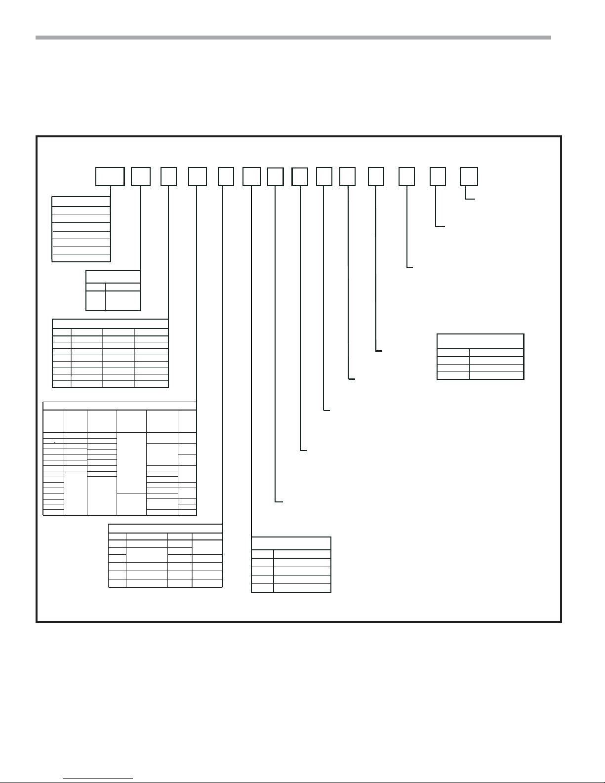
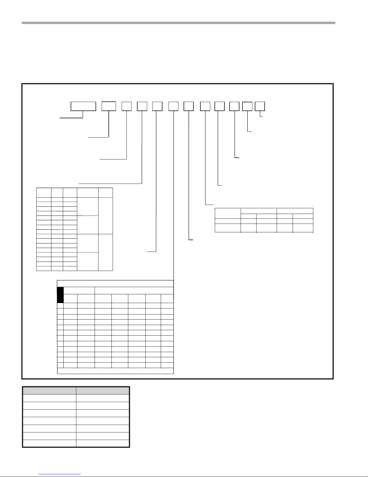
TSL Model Nomenclature - Cabinet
Heat Pump Cabinet
CABINET SIZE
1 = 09
2 = 12
3 = 15
4 = 18
5 = 24
6 = 30
7 = 36
OPTION
S.S. DRAIN PAN
–
A
B
X
C
X
–
0
–
1
X
2
3
X
4
–
HARNESS CONTROLS
PSC
STANDARD
YES
NO
YES
NO
YES
NO
YES
NO NO
ECM CONSTANT
VOLUME
OPTION
A
B
C
D
L
M
N
R
T
U
V
1
2
3
4
1 2835
D1
4
NG 0E 0 0 0 0 D
0
6
0
VOLTAGE
Volt/Hertz/PhazeOPTION
208/230/60/1
G
265/60/1
E
OPTIONS
PREMIUM SEAL
(DXM2 ONLY)
NO
YES
NO
YES
NO
YES
NO
YES
1Ý and 2Ý FILTER
X
–
X
–
X
–
X
–
ECM CONSTANT
TORQUE
A
B
C
D
E
0
1Ý
1Ý
1Ý
1Ý
2Ý
2Ý
2Ý
2Ý
S=SURFACE
M = MPC
R =REMOTE
A = ADA
A
W
R
R
A
W
R
A
W
R
L = LON
NO
M
L
NO
M
NO
M
L
NO
BREAKERDISCONNECT SWITCHOPTION
NO
YES
YES
NO
NO NO
W = WALL SENSOR
NO
YES
POWER TERMINATION
YES
NO
YES
NO NO YES
NO
ISP
NO
YES
YES
7
9
1
0
RISER STYLE
0 = SLAVE / NONE
1 = STANDARD
2 = MASTER
RISER: LOCATION
0 = None
1 = Shipped Separately
6 = Chassis ships in Cabinet (Risers Not Attached)
CABINET HEIGHT 65”
OPTION
ENO
F
L
M
ISO PAD
YES
NO
YES
10 11 12 13 14 15
STANDARD
0 = STANDARD
A, B, C etc.... = SPECIAL 1, 2, 3 etc....
T-STAT WHIP
0 = No Whip
1 = 15’ whip
2 = 25’ whip
3 = 35’ whip
A = Knock Out + Cover + No Whip
B = Knock Out + Cover + 15’ Whip
C = Knock Out + Cover + 25’ Whip
D = Knock Out + Cover + 35’ Whip
Discharge Openings
N/A
0 = Not Used
Discharge Air
E = Top Opening
Riser Ball Valve Options
0 = None
4 = Ball Valve, Union
5 = Ball Valve, Sweat
For Unit Size 65”
09 thru 12
15 thru 18
24 thru 36
REVISION LEVEL
D = CURRENT REVISION
TOPUNIT SIZE
11.5” x 6”
11.5” x 6”
12” x 16”
4
ClimateMaster Water-Source Heat Pumps
Hybrid Cabinet
THE SMART SOLUTION FOR ENERGY EFFICIENCY
Vertical Stack
Rev.: 04/24/2019
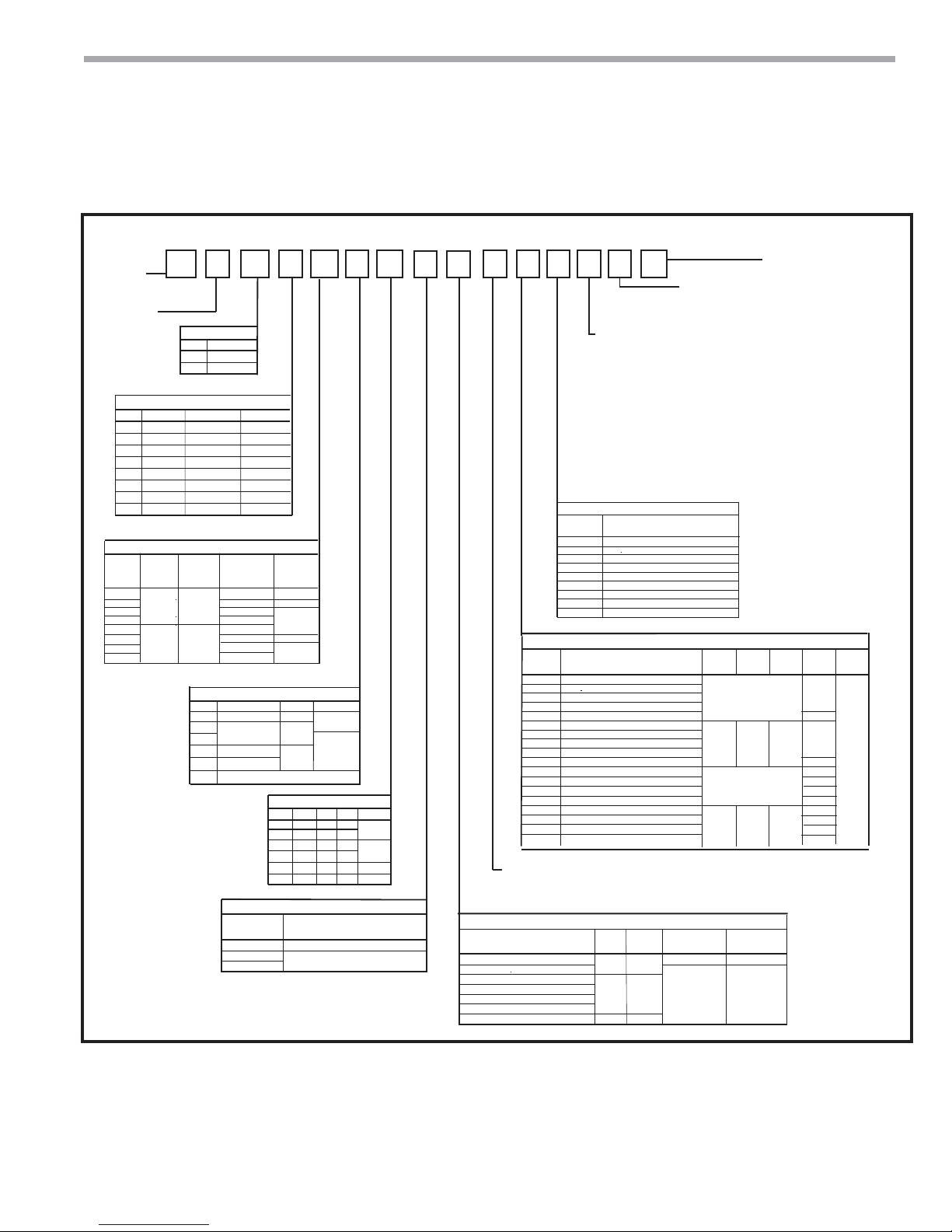
TSL Hybrid Series Nomenclature
1
SERIES
E = 65” 80” and 88”
HYBRID CABINETS
UNIT SIZE
OPTION
B
D
R
S
1
2
4
5
E
1 = 09
2 = 12
3 = 15
4 = 18
5 = 24
6 = 30
7 = 36
S.S. DRAIN PANOPTION
NO
A
YES
B
YES
C
NO
0
NO
1
2
YES
3
YES YES
4
NO NO
HARNESS CONTROLS
ECM
CONSTANT
VOLUME
YES
NO
2835
1
VOLTAGE
Volt/Hertz/PhazeOPTION
208/230/60/1
G
265/60/1
E
OPTIONS
PREMIUM SEAL
YES
NO
YES
NO
YES
NO
A = ADA
ECM
R =REMOTE
CONSTANT
S=SURFACE
TORQUE
W=WALL SENSOR
NO
YES
POWER TERMINATION
A
B
C
D
E
0
FILTER SIZE
1”
1”
1”
1”
2”
2”
2”
2”
A
W
R
S
A
W
R
S
YES
NO
YES
NO
NO OPTIONS
A
B
C
D
E
F
4
NG NA 0 0 0 0 A
0
MPC
NO
YES
NO
YES
NO
BREAKERDISCONNECT SWITCHOPTION
ISP / BREAKER
NO
NO
YES
YES
NO
CABINET HEIGHT
88”
YES
NO
NO
YES
YES
NO
NO
NO
NO
NO
NO NO
RISER STYLE OPTIONS
OPTION
0 = SLAVE/NONE
1 = STANDARD
2 = MASTER
1, 2, 3 , 4, 5, 6
6
0
65”80”OPTION
NO
NO
NO
NO
YES
YES
DIGIT 9
0, 8
ISO PAD
NO
YES
NO
YES
7
1
10 1 1 12 13 14 15
9
1
REVISION LEVEL
TYPE
0 = STANDARD
A - Z = SPECIAL EXCEPT “W”
A = CURRENT REVISION
MISCELLANEOUS CABINET OPTIONS
A = Factory Configure Supply Air Openings + Dust Protection + No Whip
B = Factory Configure Supply Air Openings + Dust Protection + 15’ Whip
C = Factory Configure Supply Air Openings + Dust Protection + 25’ Whip
D = Factory Configure Supply Air Openings + Dust Protection + 35’ Whip
0 = Field to Configure Supply Air Openings + No Whip
1 = Field to Configure Supply Air Openings + 15’ Whip
2 = Field to Configure Supply Air Openings + 25’ Whip
3 = Field to Configure Supply Air Openings + 35’ Whip
4 = Factory Configure Supply Air Openings + No Whip
5 = Factory Configure Supply Air Openings + 15’ Whip
6 = Factory Configure Supply Air Openings + 25’ Whip
7 = Factory Configure Supply Air Openings + 35’ Whip
SIDE DISCHARGE OPTIONS
DISCHARGE
OPTION
0
NONE
A
RIGHT SMALL
B
RIGHT LARGE
LEFT SMALL
C
D
LEFT LARGE
RIGHT SMALL & LEFT SMALL
E
F
RIGHT LARGE & LEFT LARGE
RIGHT SMALL & LEFT LARGE
G
RIGHT LARGE & LEFT SMALL
H
BACK/FRONT/TOP DISCHARGE OPTIONS
UNIT SIZE
OPTION
DISCHARGE
NONE
0
A
BACK SMALL
BACK LARGE
B
FRONT SMALL
C
FRONT LARGE
D
TOP
E
BACK SMALL & TOP
F
BACK LARGE & TOP
G
FRONT SMALL & TOP
H
J
FRONT LARGE & TOP
BACK SMALL & FRONT SMALL
K
BACK LARGE & FRONT LARGE
L
BACK SMALL & FRONT LARGE
M
N
BACK LARGE & FRONT SMALL
P
BACK SMALL & FRONT SMALL W/TOP
BACK LARGE & FRONT LARGE W/TOP
Q
R
BACK SMALL & FRONT LARGE W/TOP
BACK LARGE & FRONT SMALL W/TOP
S
UNIT SIZE
09-18 TOP
15-16 TOP
N/A
12 X 12 14 X 14 16 X 16
N/A
12 X 12 14 X 14 16 X 16
UNIT SIZE
24-36 TOP
C-SERIES
80”
TSM
YES
NO
YES
NO
YES
NO
NO
YES
YES
NO
NO
YES
C-SERIES
88”
TSM
YES
RISER: RISER BALL VALVE OPTIONS
4 = Ball Valve, Union
RISER LOCATION/PACKAGING OPTIONS
OPTION
0 = NONE
1 = SHIPPED SEPERATEL Y
2 = LEFT BACK
3 = RIGHT BACK
4 = LEFT SIDE
5 = RIGHT SIDE
6 = CHASSIS SHIPPED IN CABINET
5 = Ball Valves, Sweat N = None
VERTICAL
PKG
YES
NO
YES
HORIZONTAL
PKG
NO
YES
NO
VALVE ASM QTY 2
SHIPPED IN CABINET
YES
NO
VALVE ASM QTY 2
SHIPPED W/RISERS
NO
YES
climatemaster.com
5

CLIMATEMASTER WATER-SOURCE HEAT PUMPS
TSL Vertical Stack
Rev.: 04/24/2019
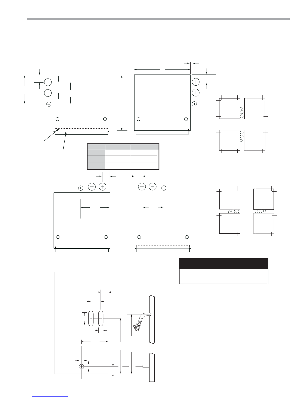
Heat Pump Cabinet Slot Dimensions and Riser Arrangements
Cabinet Shown Up to Riser
2.75”
12.00”
(305)
(70)
INNER
PANEL
S
5.00”
(127)
9.25”
(235)
R
D
FRONT OF
CABINET
STYLE 4
Risers Left
Side
RA
SIDE
2.88”
(73)
12.12”
Model
09-12
15-18
24-36
(308)
TOP VIEWS
B
A
17.00 [432]
19.25 [489]
24.25 [616] 24 [610]
SRD
STYLE 5
Risers Right
B
17 [432]
19 [483]
2.88”
(73)
SRD
9.25”
(235)
A
Side
RA
SIDE
1/4” to 1”
(6 to 25)
2.75”
S
R
D
(70)
STYLE
3 RA
STYLE
2 RA
STYLE
4 RA
STYLE
5 RA
STYLE
5 RA
STYLE
2 RA
STYLE
3 RA
STYLE
4 RA
Note 8
STYLE
2 RA
STYLE
5 RA
STYLE
3 RA
STYLE
4 RA
STYLE 3
Risers Back
Right
RA
SIDE
FRONT VIEW
STYLE 3
2.88”
(73)
12.00”
[305]
2.50”
(64)
2.25”
(57)
5.00”
(127)
12.12”
(308)
3.00”
(76)
35.75”
[908]
3.125” (all sizes)
(79)
39.75”
[1100]
± .50” (13)
Note 7
STYLE
STYLE 2
Risers Back
Left
4 RA
STYLE
3 RA
STYLE
2 RA
Note 8
RA
SIDE
NOTICE!
NOTICE! Not all styles will stack above
or adjacent to each other. (See Note 8).
Notes:
1. Dimensions are inches [mm].
2. Style refers to cabinet to riser confi guration.
3. Return air side is the front of the cabinet.
4. Supply riser is closest to corner.
5. Drain is not centered on all cabinets
6. Slots allow for riser stack expansion and
contraction.
7. Riser stub out is 39.75" (1100) from bottom cabinet and
is not centered in slot.
8. From fl oor to fl oor on one riser stack you can only
have; all same style, styles 2 and 5; or styles 3 and 4.
For master/slave units you can only have styles 3 or 4
adjacent to 2 or 5.
STYLE
5 RA
6
ClimateMaster Water-Source Heat Pumps
Cabinet Shown Up to Riser
2.75”
12.00”
(305)
(70)
S
5.00”
(127)
R
9.25”
(235)
D
STYLE 4
Risers Left
THE SMART SOLUTION FOR ENERGY EFFICIENCY
Vertical Stack
Rev.: 04/24/2019
E Cabinet Slot Dimensions and Riser Arrangements
1/4” to 1”
(6 to 25)
2.75”
S
R
D
(70)
STYLE
3 RA
STYLE
4 RA
STYLE
5 RA
STYLE
2 RA
Side
TOP VIEWS
B
A
STYLE 5
Risers Right
Side
INNER
PANEL
FRONT OF
CABINET
FRONT VIEW
RA
SIDE
2.88”
(73)
STYLE 3
Risers Back
Right
RA
SIDE
STYLE 3
Model
09-12
15-18
24-36
12.12”
(308)
17.00 [432]
19.25 [489]
24.25 [616]
SRD
RA
A
B
SIDE
20.00 [508]
22.00 [559]
27.00 [686]
2.88”
(73)
SRD
9.25”
(235)
STYLE 2
Risers Back
Left
STYLE
2 RA
STYLE
5 RA
STYLE
4 RA
STYLE
5 RA
STYLE
2 RA
STYLE
3 RA
STYLE
Note 8
STYLE
3 RA
4 RA
STYLE
3 RA
STYLE
4 RA
STYLE
5 RA
STYLE
2 RA
Note 8
RA
SIDE
NOTICE!
NOTICE! Not all styles will stack above
or adjacent to each other. (See Note 8).
2.88”
(73)
5.00”
(127)
12.00”
[305]
2.50”
(64)
12.12”
(308)
2.25”
(57)
3.00”
(76)
35.75”
[908]
3.125” (all sizes)
(79)
39.75”
[1100]
± .50” (13)
Note 7
climatemaster.com
Notes:
1. Dimensions are inches [mm].
2. Style refers to cabinet to riser confi guration.
3. Return air side is the front of the cabinet.
4. Supply riser is closest to corner.
5. Drain is not centered on all cabinets.
6. Slots allow for riser stack expansion and
contraction.
7. Riser stub out is 39.75" (1100) from bottom cabinet and
is not centered in slot.
8. From fl oor to fl oor on one riser stack you can only
have; all same style, styles 2 and 5; or styles 3 and 4.
For master/slave units you can only have styles 3 or 4
adjacent to 2 or 5.
7
CLIMATEMASTER WATER-SOURCE HEAT PUMPS
TSL Vertical Stack
Rev.: 04/24/2019
TSL Model Nomenclature - Chassis
Chassis
T S L
Series
TSL = TRANQUILITY®
HIGH RISE CHASSIS
Unit Size
09
12
15
18
24
30
36
Chassis Options
S.S.
OPTION
Drain
Ultraquiet
Pan
A
B
C
S
D
E
F
G
H
K
L
M
N
P
Q
R
NO
YES
YES
NO
YES
YES
NONO
NO
YES
YES
NO
YES
YES
NONO
NO
YES
YES
NO
YES
YES
NONO
NO
YES
YES
NO
YES
YES
NONO
AUTO-FLOW REGULAT OR (US GPM) CODE
5/8 SWEAT
UNIT
09
1.5 - - - - - -
C
D
2.0
2.5
E
3.0
F
-
G
-
H
-
J
K
--
L
----
M
----
N
-----
P
S = STANDARD - NO FLOW REGULATOR
1 2 3
Voltage
E = 265/60/1
G = 208/230/60/1
For
Communicating
T-Stat
NO
YES
NO
YES
UNIT
12
2.0
2.5
3.0
3.5
UNIT
-
-
4 5 6 7 9 10 11 12 13
09 G
RIB
RELAY
8
S S S C S
A
Shipping
6 = Chassis Will Ship In Cabinet
S = Standard
Heat Exchanger Options
NO
Position 11
Standard Tubing
Insulated Tubing
(Extended Range)
Water Valve & Pump Option
S = No Water Options
YES
Controls
A = CXM
B = DXM2
7/8 SWEAT
UNIT
18
15
-----
2.5 - - - -
3.0 - - -
3.0
3.5
3.5
4.0
4.0
-
5.0-5.0
-
-
-
-
UNIT30UNIT
UNIT
24
---
4.0
6.0
7.0
-
-
36
--
-
5.0
6.0
6.0
7.0
7.0
8.0
8.0
-
9.0
10.0
-
M = 2-Way Water Valve (Normally Closed)
N = 2-Way Water Valve (Normally Open)
P = Secondary Circulating Pump
T = Modulating Water Valve
H = Hybrid with Standard Water Valve (Normally Closed)
J = Hybrid with Standard Water Valve (Normally Open)
L = Hybrid with 3-Way Water Valve
K = Hybrid with Secondary Water Pump and 3-Way Water Valve
15
14
A
S
C
Revision Level
C = Current Revision Level
Standard
S = Standard
A = Special #1
B = Special #2
Etc.....
Blower Motor
A = PSC High Static
C = ECM Constant Torque
D = ECM Constant Volume
Tin Plated Air Coil Non-Coated Air Coil
Copper
Cupro-nickel Cupro-nickelCopper
C
DE
NL
(Risers Not Attached)
M
FG
Chassis Cabinet
09 D1/E1
12 D2/E2
15 D3/E3
18 D4/E4
24 D5/E5
30 D6/E6
36 D7/E7
8
ClimateMaster Water-Source Heat Pumps
Hose Kit
THE SMART SOLUTION FOR ENERGY EFFICIENCY
Vertical Stack
Rev.: 04/24/2019
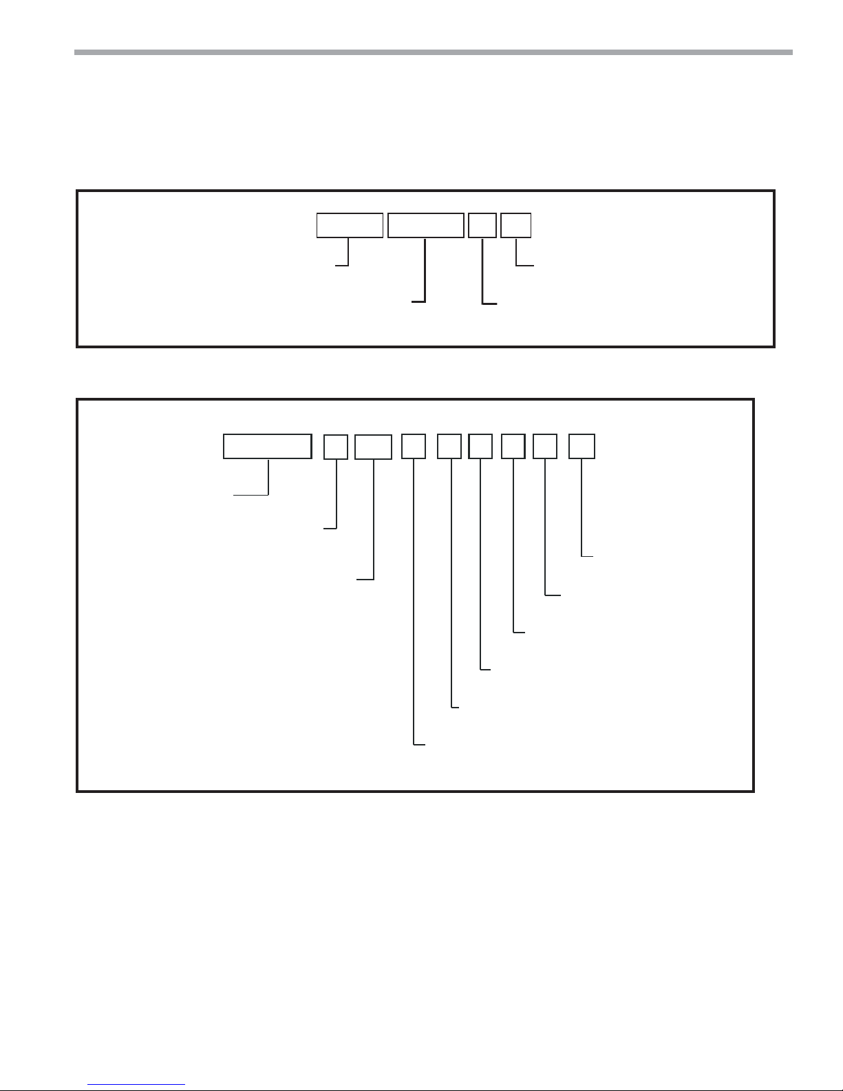
Accessory Nomenclature
1 2 3 4 5 6 8
7
0 5 0A H H B3
AHH = Accessory Hose Kit
AHU = Accessory Hose Kit
Note: If cabinet digit 10 is 4
use AHH; 5 use AHU
Group
Cabinet Stands (Ship loose in bulk)
1 2 3 4
ACST
Accessory
Cabinet Stand
TSM/TSL
CABINET SIZE
0 = 17” x 17”
1 = 19” x 19”
2 = 24” x 24”
3 = 17” x 20”
4 = 19” x 22”
5 = 24” x 27”
050 = 1/2” Nominal
075 = 3/4” Nominal
5
0
HEIGHT
01 = 1”
02 = 2”
03 = 3”
04 = 4”
05 = 5”
06 = 6”
07 = 7”
08 = 8”
09 = 9”
10 = 10”
11 = 11”
12 = 12”
13 = 13”
Hose Size
100 = 1” Nominal
7
6
01
8
0
10
9
0
0
FUTURE USE
0 = STANDARD
Revision Level
B = Current Revision
Length
3 = Length in Feet
011012B
FUTURE USE
0 = STANDARD
FUTURE USE
0 = STANDARD
13
REVISION
B = CURRENT REVISION
FUTURE USE
0 = STANDARD
ISO PAD
0 = STANDARD (NO ISO PAD)
1 = ISO PAD
climatemaster.com
9
CLIMATEMASTER WATER-SOURCE HEAT PUMPS
TSL Vertical Stack
Rev.: 04/24/2019
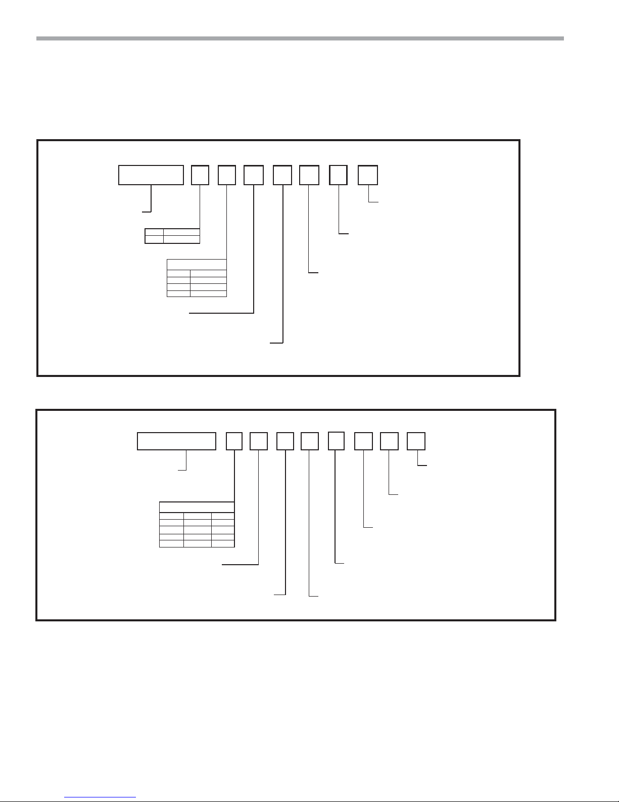
Accessory Nomenclature
Return Air Panel “G”
A V H S 1 S F S S
ACCESSORY VHS
RETURN AIR PANEL
Return Air Panel “L”
1 2 3 4
TYPE
“G”
5
G
DESCRIPTION
Removable
UNIT WIDTH
WIDTH
OPTION
17”
1
19”
2
24”
3
789
6
STYLE
A = DOOR w/ADA TSTAT MOUNTING
C = DOOR w/ADA TSTAT MOUNTING & LOCK
L = DOOR w/KEY LOCKS (18 GA. SHEET METAL)
S = STANDARD (20 GA. SHEET METAL)
COLOR
S = STANDARD (POLAR ICE)
W = BRIGHT WHITE
INSULATION TYPE
F = FIBERGLASS
1 2 3 4 5
789
6
A V H R L 1 S F S 0
10
11
N
STANDARD
S = STANDARD
REVISION LEVEL
N = CURRENT REVISION TSM (”G” PANEL)
10
F
11
13
A12S
ACCESSORY VS
RETURN AIR PANEL
AVHRL = L-PANEL
UNIT WIDTH
OPTION WIDTH
1
2
3
4
TSM/TSL
17”
09 - 12,
19”
15, 18
24
24”
24”
30 - 36
COLOR
S = STANDARD (POLAR ICE)
W = BRIGHT WHITE
INSULATION TYPE
F = FIBERGLASS
COMPONENT
F = FRAME
P = PANEL
STYLE
S = STANDARD
STANDARD
S = STANDARD
REVISION LEVEL
A = CURRENT REVISION
RESERVED FOR FUTURE USE
0 = STANDARD
10
ClimateMaster Water-Source Heat Pumps

THE SMART SOLUTION FOR ENERGY EFFICIENCY
Vertical Stack
Rev.: 04/24/2019
Pre-Installation Information
Storage -
packaging in a clean, dry area. Store chassis in an upright
position at all times. Stack units at a maximum of 2 units high.
Store cabinets how they were shipped - vertical, keeping
them on their pallets for protection. Do not stack
multipacks. Store risers in secure area. ClimateMaster will
not replace missing risers.
Unit Protection -
the original packaging or an equivalent protective
covering. Cap the open ends of pipes stored on the
job site. In areas where painting, plastering, and/or
spraying has not been completed, all due precautions
must be taken to avoid physical damage to the units and
contamination by foreign material. All openings in cabinet
must be covered during all stages of construction. Physical
damage and contamination may prevent proper start-up
and may result in costly equipment clean-up.
Examine all pipes, fi ttings, and valves before installing
any of the system components. Remove any dirt or debris
found in or on these components.
Prior to fl ushing risers with water, be sure that the
temperature in building will always be above freezing.
Pre-Installation -
Maintenance instructions are provided with each unit. The
installation site chosen should include adequate service
clearance around the unit. Before unit installation and
start-up, read all manuals and become familiar with the
unit and its operation. Thoroughly check the system
before operation.
Your installation may require additional, different
sequence, or modifi cation to steps in this IOM.
Equipment should be stored in its original
Cover units on the job site with either
Installation, Operation, and
7. A base vibration dampening pad is recommended to
help eliminate transfer of vibration to the structure.
If isolation pad was not ordered, obtain of 0.070” to
0.125” (1.5 to 3) thick pad and apply to the bottom
of the cabinet.
8. For chassis shipped inside cabinet remove and discard
4 shipping bolts.
9. Remove inner panel (8 screws) and save for
reinstallation after chassis is installed.
10. For standard cabinets remove and discard condensate
pan shipping wire ties.
Prepare chassis for installation as follows:
1. Verify refrigerant tubing is free of kinks or dents and
that it does not touch other tubes or unit parts as it
passes over or through. Adjust if needed and separate
with closed cell insulation.
2. Inspect all electrical connections. Connections must
be clean and tight at the terminals.
3. If chassis is not installed in cabinet, store in
original carton in a clean and dry location.
WARNING!
WARNING! To avoid damage from clogged coil surfaces,
clogged motor ventilation openings, seized fan blades and
potential unit failure, DO NOT OPERATE UNIT without
complete enclosure, supply grille, return air panel and fi lter in
place.
CAUTION!
CAUTION! DO NOT store or install units in corrosive
environments or in locations subject to temperature or
humidity extremes (e.g., attics, garages, rooftops, etc.).
Corrosive conditions and high temperature or humidity can
signifi cantly reduce performance, reliability, and service life.
Always move and store units in an upright position. Tilting
units on their sides may cause equipment damage.
Prepare cabinet for installation as follows:
1. Compare the electrical data on the unit nameplate
with ordering and shipping information to verify that
the correct unit has been shipped.
2. Each cabinet has a tag to indicate the location to be
installed.
3. Keep the cabinet openings and exposed sheet
metal covered until installation is complete and all
plastering, painting, etc. is fi nished and cleaned.
4. Inspect all electrical connections. Connections must
be clean and tight at the terminals.
5. Remove correct riser knockouts, slit insulation vertical
down center (do not remove).
6. Repair any torn insulation with foil tape.
CAUTION! CUT HAZARD - Failure to follow this caution may
result in personal injury. Sheet metal parts may have sharp
edges or burrs. Use care and wear appropriate protective
clothing, safety glasses and gloves when handling parts and
servicing heat pumps.
climatemaster.com
CAUTION!
11
CLIMATEMASTER WATER-SOURCE HEAT PUMPS
5
3
Low Voltage Exit
For Remote Thermostat
(Optional Whip Exit)
2
High Voltage Entry
4
Do not
drive screws
into this area
both sides
Service Area
Note
24”
(610)
2”
(50)
and this area
far side
TSL Vertical Stack
Rev.: 04/24/2019
Riser Installation
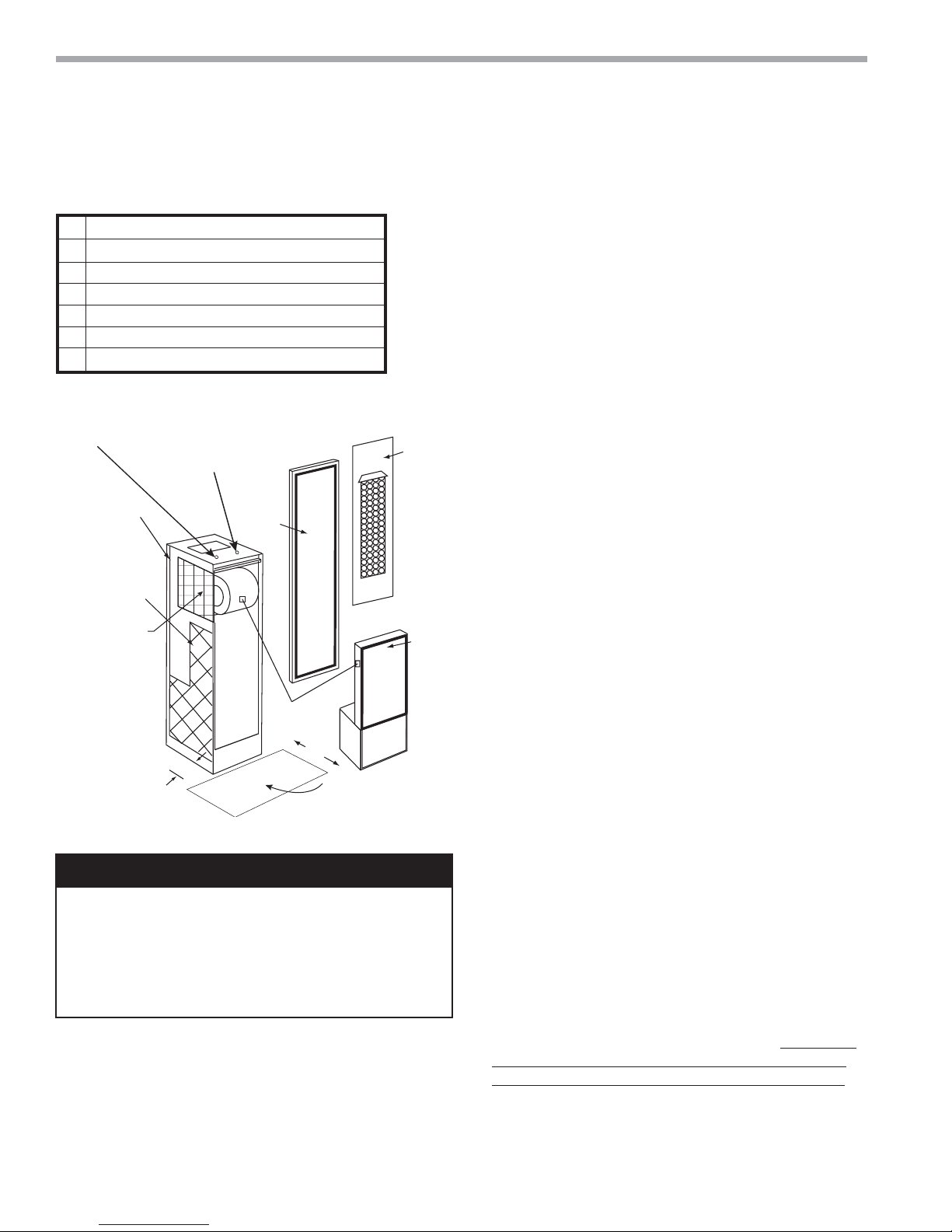
Figure 1: Vertical Stack Unit Components
1 Supply, Return, and Condensate Risers (not shown)
2 Cabinet
3 Cabinet Inner Panel and Filter
4 Chassis
5 Return Air Panel
6 Thermostat (Not shown)
7 Hoses (Not shown)
Note:
Matching
labels for
visual aid,
chassis, and
cabinet same
size and
voltage.
WARNING! To prevent electrical shorts and drain pan leaks,
assure that screws do not penetrate unit components when
driving screws near the unit control box or drain pan. Do not
allow screws or nails to penetrate chassis, risers, electrical
junction boxes, raceways or to interfere with chassis removal.
To avoid motor or compressor damage, keep drywall dust out
of the unit.
12
WARNING!
Core Drilling For Vertical Riser Stack
Core drilling slab slot/holes will determine cabinet place-
Install
Now
}
Install
Later
}
ClimateMaster Water-Source Heat Pumps
ment and surrounding walls. Slot/holes size, location on fl oor
and plumb alignment in two planes from top to bottom are
all very important, check plans. Size of slot/hole will depend
on slab thickness, ceiling height, riser length. See TSL submittal.
Risers -
in crates. Crates will have layers of risers by fl oors, each
cabinets 3 risers (S,R,D) will be next to each other. Lowest
fl oor will be on top layer. Risers will have tag with fl oor,
riser number (if fi lled out on EZ Order). Entire riser stacks
can be assembled, pressure tested, fl ushed, and fi lled
before setting cabinets. Use caution if fi lled risers are in
unconditioned space, prevent freezing. Do not construct
walls until cabinets are set.
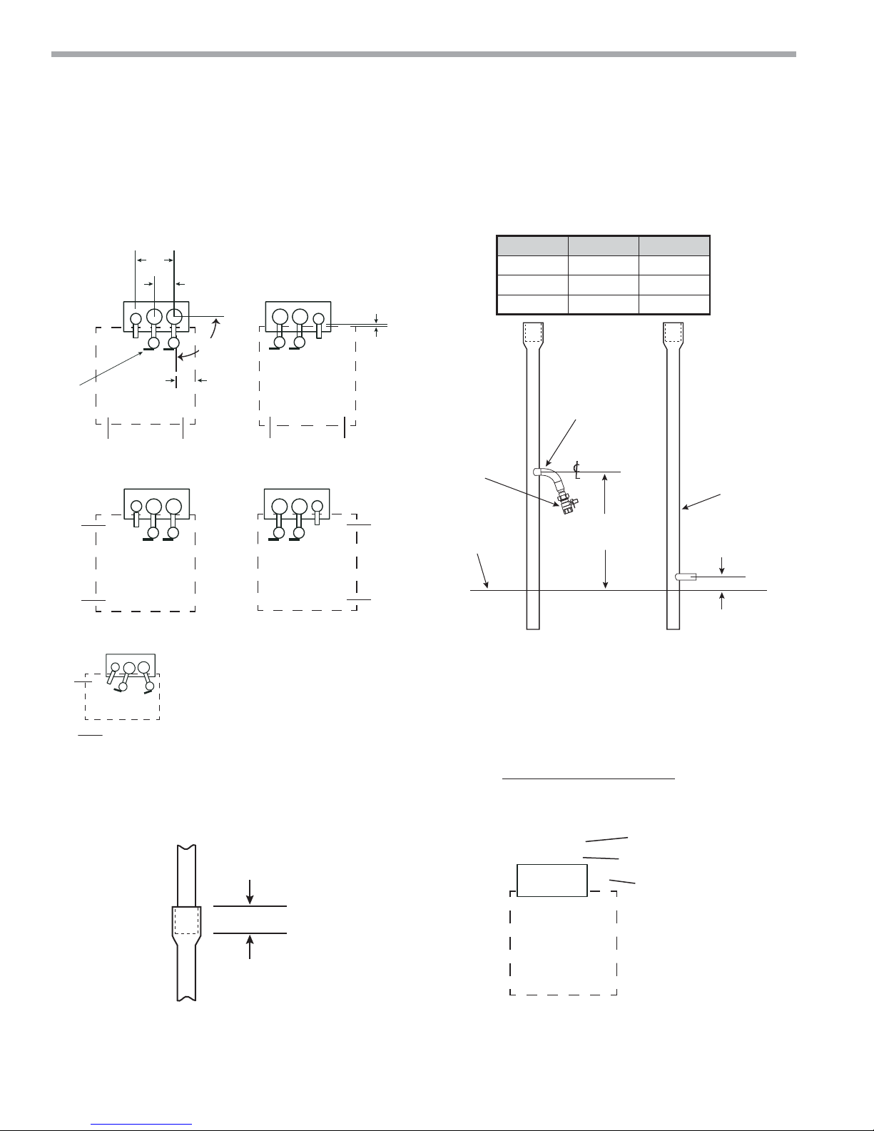
Description - Supply and return risers can be straight,
transition up, transition down, bottom capped, or top
capped. Drain risers can be straight, transition up, or top
capped. All drain risers and extended range (operation
below 60 ºF entering water temperature) supply and return
risers need insulation. Repair or replace any damaged or
missing insulation.
Type M has red identifi cation marking (stripe running down
the tube) and Type L (thicker wall) has blue identifi cation
marking.
If tube is insulated pull back carefully to check color.
Shutoff and hose size for cabinet/chassis- ½” for D1 (09) and
D2 (12); ¾” for D3 (15) and D4 (18); 1” for D5 (24), D6 (30),
and D7 (36).
Supply riser is always closest to back corner of cabinet,
return riser next, and drain riser in approx. middle of the
cabinet. Risers are 9.25” (235) apart on centerline. See
Figure 5.
1. Check riser diameter, type, valve size, and position
2. Suggest each cabinet location be marked with all
3. Starting on lowest fl oor center risers in slot. Set height
4. If riser extensions are used insert them on lower fl oor
Risers are ordered loose and will be shipped
Note: Type L may be substituted for type M.
(S,R,D or D,S,R) of risers per cabinet confi guration (see
fl oor plans).
information (see fi gure 5 ).
of supply and return runouts to 39.75” (1100) and
drain runout to 3.12” (79) from bottom of cabinet.
Temporally secure risers (not by runout or valve) so they
do not move.
top of riser , mark like step 5.

THE SMART SOLUTION FOR ENERGY EFFICIENCY
Vertical Stack
Rev.: 04/24/2019
5. Next fl oor up mark riser at bottom at 1” (25) and 2.50”
(63), drop through slot and position runouts same as
step 2. Temporally support.
6. On lower fl oor check that above riser is inserted
between 1” (25) and 2.50” (63) (between 2 marks you
made). Cut riser if needed or use extension.
CAUTION!
CAUTION! To ensure correct riser positioning and to
compensate for variations in fl oor-to-fl oor dimensions, do not
allow the unit to unit riser joint to bottom out.
7. Insert expansion devices if required by plans.
8. Continue until complete riser stack is assembled.
9. Check all risers are correct diameter , type, valve size;
correctly positioned; centered in slot; plumb from top to
bottom; depth into swedge correct; runouts at correct
height, and shutoff valve handles are parallel with the
side of cabinet. (see Figure 2)
10. Braze all joints with high temperature alloy like Phoscopper or Silfos. (DO NOT use soft solder 50-50, 60-40
or 85-15; low temperature alloys are not acceptable for
this application).
11. Must securely anchor riser stacks to building structure
at least on one fl oor. Typically at middle fl oor and
additional fl oors as needed. Example: 40 fl oors, anchor
at 10, 20, and 30. Use expansion devices between
anchors.
12. Remove temporary supports.
13. Check that risers did not drop. If stack dropped, jack up
and add additional anchor support.
14. V erify all shutof f valves are closed. DO NOT OPEN
VALVES until system has been cleaned and fl ushed.
15. Pressure check risers–locate and r epair any leaks–r etest
during installation.
NOTICE
location, brazed incorrect, modifi ed incorrect (including
cutting off or extending), runoff at incorrect height,
Supply and Return Stack
1. Install a drain valve, shut-off/balancing valves, fl ow
2. Install strainers at the inlet of each circulating pump.
3. Insulate loop water piping which runs through
4. Cabinet slots and riser stack assemblies are designed
5. Installer must remove riser knockouts (2). Replace and
Condensate Stack - All TSL cabinets - installer must
remove drain knockout and connect drain pan to riser
Installer must clip and remove 2 drain pan shipping ties,
lift drain pan, cut drain hose to length, connect to drain
pan and riser, and clamp both ends. For slave cabinets
- suggest extending drain stub into cabinet so clamp is
accessable.
If local codes allow-PVC drain risers may be used. All
couplings and reducers are to be fi eld supplied.
: Any risers misplaced, assembled in wrong
indicators and drain tees at the base of each supply and
return riser stack to enable system fl ushing at start-up,
balancing and during servicing.
nonconditioned areas or outside the building. For
boiler tower applications loop temperature is normally
between 60°F and 90°F, piping does not sweat or suffer
heat loss under ambient conditions. For geothermal
applications insulate all loop water piping.
to accommodate a maximum of 1-½”(38) expansion
and 1-½”(38) contraction. If the calculated riser stack
expansion or contraction exceeds 1-½”(38), expansion
devices must be provided.
seal any KO’s removed by mistake.
.
Secure Riser Stack to building structure so stack does not
drop over time. Cabinet slots allow for 1.50” (38mm) maximum expansion and 1.50” (38mm) maximum contraction,
use expansion devices if you exceed these values.
To facilitate cleaning and fl ushing, install the hose kit at
the end farthest from the pump and connect the ends
of the hoses with the riser fl ush adapter (Kit - AFL5751).
Then open both valves before pumping fresh water
through the system, close the valves when the system
is clean. Remove the fl ush adapter before installing the
chassis.
Note: Refer to System Flushing Section of this manual
for more information.
Install air vents in piping loop at highest accessible point
as required to bleed the system of air accumulated
Misalignment found anytime including when cabinets are
set, not using expansion devices if specifi ed, or stack was
not supported correctly is the sole responsibility of the
installing contractor.
climatemaster.com
13
CLIMATEMASTER WATER-SOURCE HEAT PUMPS
TSL Vertical Stack
Rev.: 04/24/2019
Figure 2: Riser Placement Figure 3: Riser Setting Detail
Shuto
Handle
RA
Side
DR S
Style 3
Only
RA Side
DR S
Style 4
Only
DR S
9.25
(235)
5.00
90°
±3°
2.75
(70)
Note: Cabinet Model Digit 9 Indicates Style
SRD
Style 2
Only
RA Side
SSRSR D
Style 5
Only
1/4” to 1” GAP
(6 to 25mm)
RA
Side
Cabinet Size Valve FPT
D1, D2 09, 12 1/2“ (13)
D3, D4 15, 18 3/4” (19)
D5, D6, D7 24, 30, 36 1” (25)
Runout
Shuto
Valve
Bottom of
Cabinet
Supply and Return Drain
39.75 (1100)
± .50 (13)
Always
Insulated
3.12 (79)
± .12 (3)
Not Acceptable
Figure 4: Riser or Extension Insertion
1.00 Min (25)
2.50 Max (63)
14
Figure 5: Suggested Floor Markings
(Change data for your unit)
(
/
¹
¹
(S) (R) (D)
Model (
Size (12)
Style (5)
Tag (_)
Riser Number (_)
ClimateMaster Water-Source Heat Pumps
)(
Slot
Riser DIA
/
)(
/
)
¹
¹
¹
¹
Top/Bottom
DIA Placement
/
¹
²
Valve Size
D2)
(
(
RA
Side
THE SMART SOLUTION FOR ENERGY EFFICIENCY
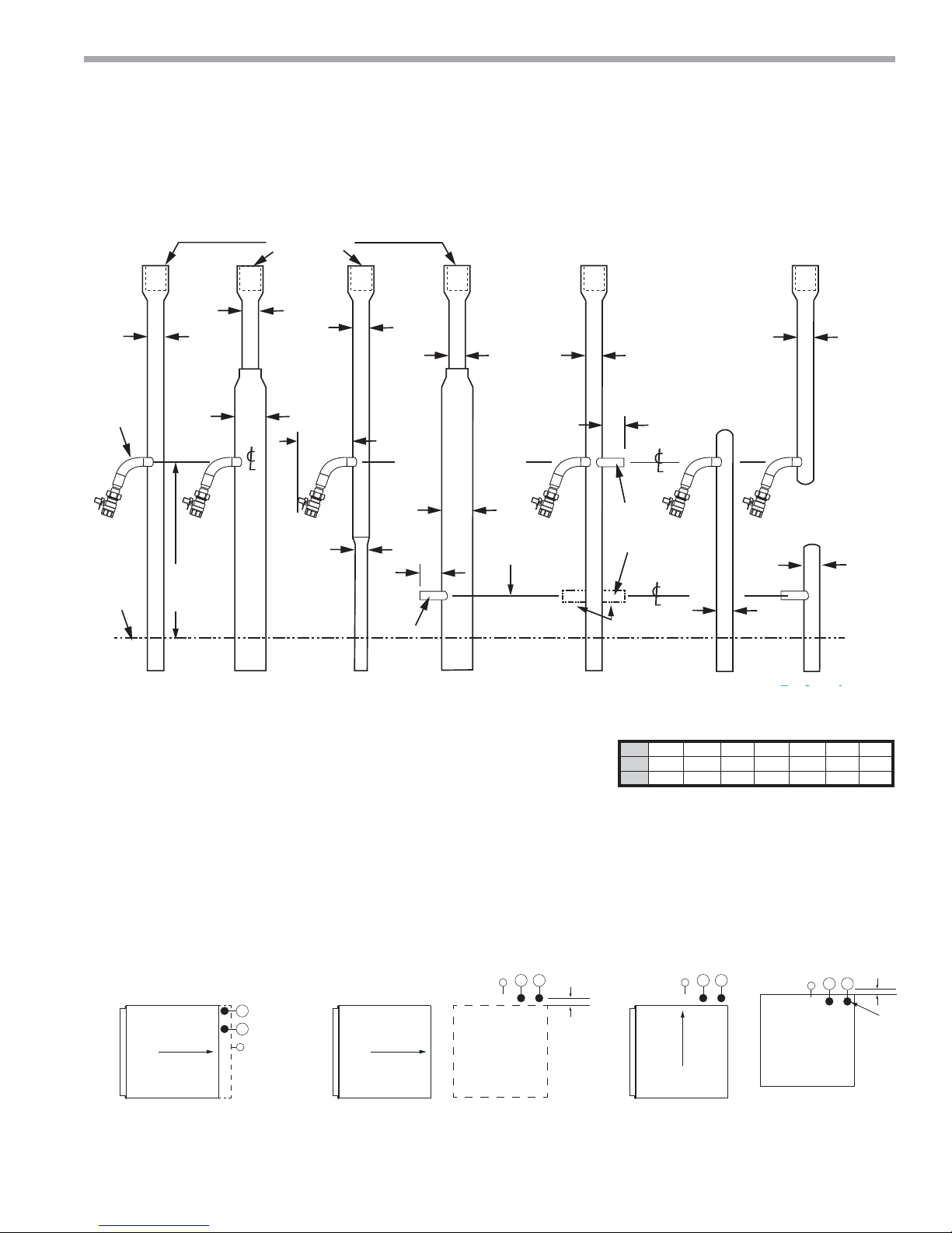
Figure 6: Riser Identifi cation
Propress Riser
is straight (no swage)
Standard Riser
Swaged 3” Deep
For A Dia. Riser
From Above
A Dia.
Shutoff
Valve
Assembly
Runout
Into
Cabinet
Bottom of
Cabinet
Runout
Into
Cabinet
39.75
(1100)
± .50ß (13)
(Note 10)
A Dia.
B Dia.
Runout
Into
Cabinet
6.00
(152)
MAX
A Dia.
C Dia.
3.00
(76)
Drain Runout
Into Cabinet
A Dia. A Dia.
B Dia.
3.12 (79)
± .50ß (13)
(Note 10)
Runout
Into
Cabinet
Runout
for Slave
Cabinet
(Note 8)
Drain Only
3.00
(76)
Runout
Into
Cabinet
Vertical Stack
Rev.: 04/24/2019
A
Bottom Capped
Supply and Return
A
A
Notes:
1. Y ou must know water fl ow direction to determine if cabinet requires
transition up or down.
2. T ransitions can only change by one diameter (1" to 1¼", 1¼" to 1½", etc.)
3. Riser transition couplings and runouts are factory brazed.
4. All risers are factory pressure tested.
5. Standard riser diameters are 1", 1¼", 1½", 2", 2½" and 3"nominal water tubing.
6. Copper Type M and L available.
7. Drain riser insulated standard. Supply and return insulated optional.
8. Master riser - contractor provides tubing from runout to slave cabinet if needed
and brazes shutoff for slave.
9. Shutoff and hose size 1/2” for C1(09), C2(12); 3/4” for C3(15), C4(18); or 1” for
C5(24), C6(30), C7(36).
10. Position runout perpendicular to side of cabinet.
When cabinets are pushed up to risers allow suent clearance.
Shutos should be inside cabinet.
Push Push
Step 1
Risers Opposite
Return Air Opening
Risers Adjacent to
Return Air Opening
A 1.00 1.25 1.50 2.00 2.50 3.00 4.00
B 1.25 1.50 2.00 2.50 3.00 - -
C - 1.00 1.25 1.50 2.00 2.50 -
Note - All ClimateMaster units with
optional motorized valve have water
high pressure switches. Do not design
riser stack where switch will not reset.
(Trip - 300 PSI; Reset - 250 PSI)
Approx.
6”
(152)
Push
Step 2Step 1
Final
Cabinet Postion
1/4” to 1”
(6 to 25)
Shutos
Inside
climatemaster.com
15

CLIMATEMASTER WATER-SOURCE HEAT PUMPS
TSL Vertical Stack
Rev.: 04/24/2019
Cabinet Installation
Cabinet Installation
1. Check plans that cabinet is correct for location,
cabinet will have tag and data plate with information,
including unit size, diameters of risers, and electrical
data.
2. Remove riser KO’s (3) for your cabinet confi guration
(see fi gure 2).
3. Cover supply and return openings with 4 pads. Slit
with knife (see fi gure 7).
4. Slide cabinet up to riser allow 1/4” to 1” (6 to 25mm)
clearance.
5. Attach the cabinet assembly to the fl oor on at least two
sides using sheet metal angles. Additional anchorage
may be provided by installing brackets at the top of the
cabinet.
a. Anchor built-in risers to the building structure
with at least one contact point. To accommodate
vertical expansion and contraction DO NOT fasten
risers rigidly within the unit.
b. Verify that unit shut-off valves are closed. DO NOT
OPEN VALVES until the system has been cleaned
and fl ushed.
6.
For cabinets with chassis inside - remove 4 shipping
screws, discard.
7. Remove inner panel (8 screws), save both.
8.
Remove condensate pan shipping wire ties.
9. P-Trap Hose must be connected, lift drain pan, and
clamp to riser stub and pan. If condensate hose must
be rotated, loosen clamp on pan, rotate, and reclamp.
Check condensate drain - clean pan if needed. Slowly
pour 1 to 2 quarts (1 to 2 liters) of water into pan.
Water should drain freely. Check for water in cabinet
and on fl oor. Repair if needed, Retest.
10.
Sheet metal ductwork should not be attached to
the cabinet. A canvas-type fl exible connection is
recommended between the cabinet and the ductwork.
11. Optional Electric Heater – Single point power to unit.
Note: Steps 6-10 do after drywall installation.
Figure 7
Slit
Through
Cover S/R Openings
with 4 Pads
NOTICE! ClimateMaster is not responsible for drywall repair
if 2 x 4 box was not in correct orientation.
Optional Frame for G Return Air Panel -
cabinet) Position studs in front of cabinet and install frame
in opening. Seal the gap between the cabinet and the
frame. If fresh air motorized damper assembly is used,
fi eld fabricate and install duct from outside to frame
opening. Assembly is installed later. See instructions with
assembly. NOTICE! Allow for drywall thickness under
frame front fl ange. Must use damper motor assembly if
fresh air is needed.
Optional Field Supplied Return Air Duct Installation
-
When return air is required to enter the unit through
openings in a stud wall, supply and fi eld install an optional
duct. Seal duct against the return air opening with foam.
Ensure that all air entering the unit passes through the
fi lter and refrigerant-to-air coil. Note: Chassis must be
removable for service.
Drywall Installation
For best sound attenuation, it is recommended not to
attach drywall to cabinet. Install studs and drywall using
conventional construction methods. Secure drywall to
studs with low profi le, pan-head sheet metal screws.
Drywall can be attached directly to cabinet (except in
places indicated in Fig 1), front of cabinet requires double
thickness. Must not be fastened to drain pan edges or
control box enclosure. Do not attach studs to cabinet. Do
not install drywall using adhesive alone.
See typical construction fi gures to determine stud layouts
and dimension from cabinet to fi nished wall.
Vacuum all drywall dust and construction debris from
cabinet insulation, drain pans and blower discharge
plenum after cutting out supply. Insulation should be
placed between the drywall and the cabinet for sound
attenuation.
When drywall installation is complete, cover all cabinet
openings and exposed sheet metal. (Cardboard from unit
shipping cartons can be used). Do not allow paint or wall
texture over-spray to contact insulation, sheet metal, coil,
fan or other unit components. Warranties are void if paint
or other foreign debris is allowed to contaminate internal
unit components.
NOTICE!
(See recessed
Cabinet Side
16
ClimateMaster Water-Source Heat Pumps
THE SMART SOLUTION FOR ENERGY EFFICIENCY
Vertical Stack
Rev.: 04/24/2019
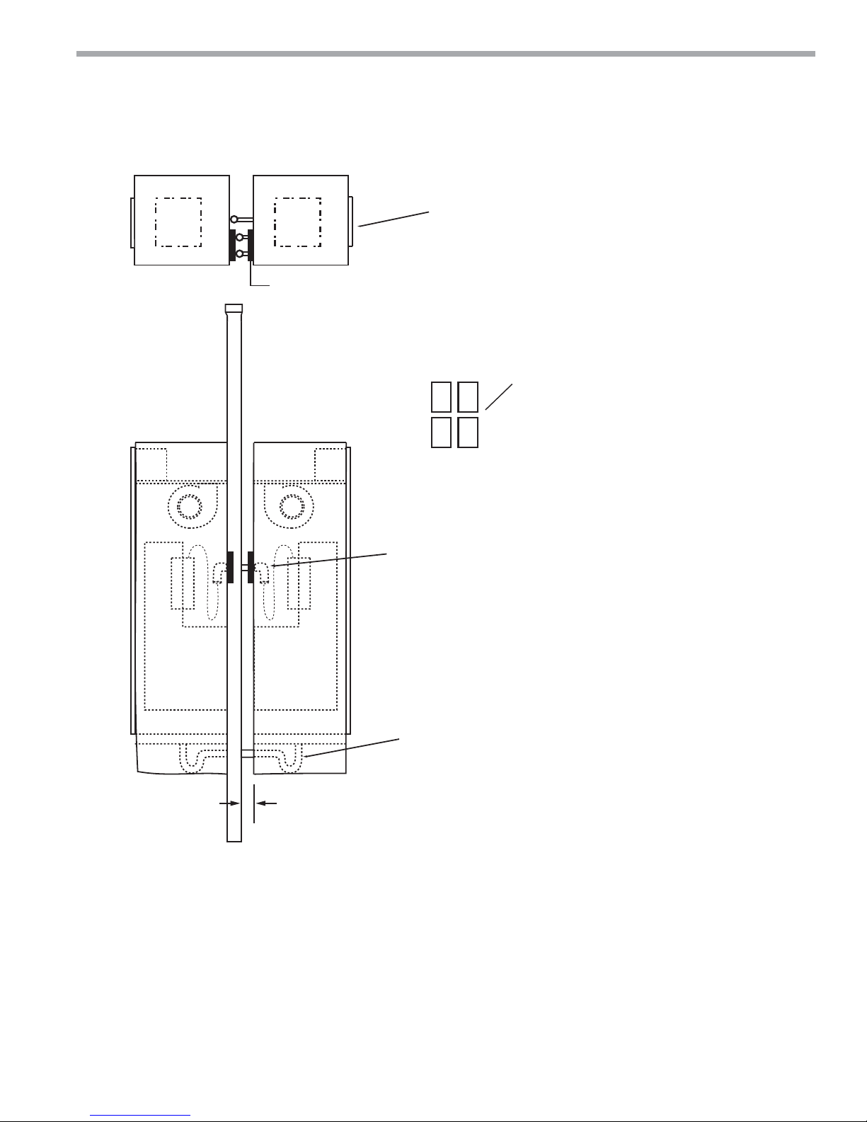
Master/Slave Cabinet Installation
RA
R
R
RS
S
(Note 4)
S
RA
Field connect
hoses in both cabinets-
supply to supply and return to return.
(Cabinet supply is closest to corner,
chassis supply is on left facing air coil)
Slave Cabinet
Riser Pads (4)
Note 4
Field braze valve package
slave side (shut off with tubing).
(Note 5) Shuttoff handle to be
inside cabinet.
2” (50) Minimum
extend copper stubs
for S/R/C if over 3” (75)
Master Slave
Field install P-Trap and clamp
both ends. Suggest hard drain
connection be extended into
cabinet so clamp is always
accessable.
Notes:
1. Contractor must meet all fi re code requirements.
2. Size riser diameter for both units GPM.
3. Master/Slave means both units share common riser.
4. Install pads on back of slave cabinet to cover slots used for S/R risers.
climatemaster.com
17
CLIMATEMASTER WATER-SOURCE HEAT PUMPS
TSL Vertical Stack
Rev.: 04/24/2019
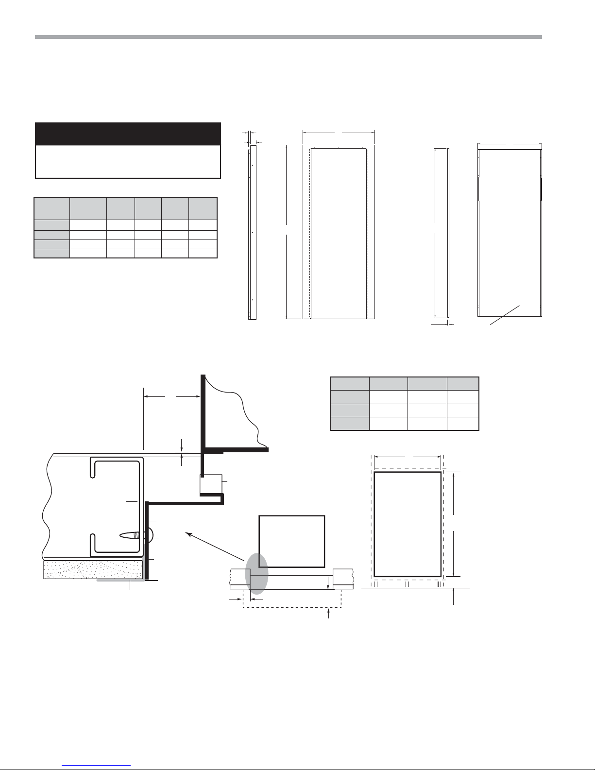
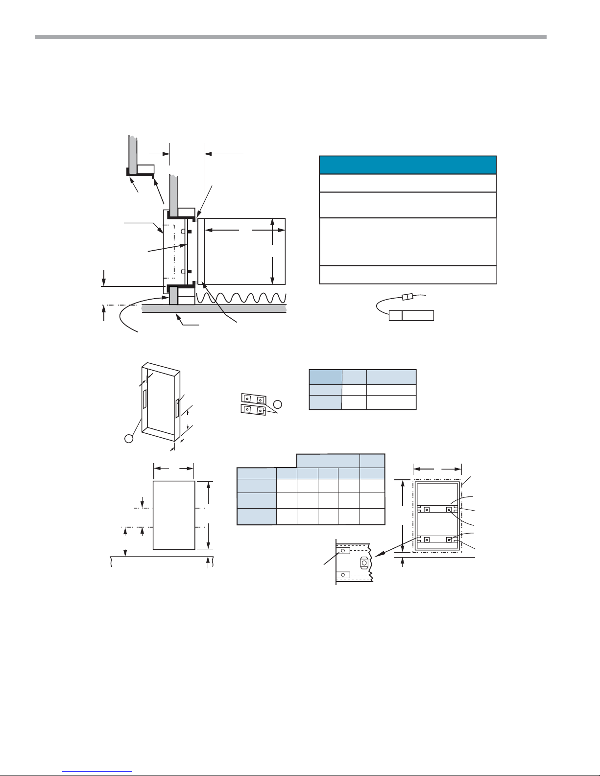
Typical Cabinet with L Return Flush Mounted Air Panel Installation
NOTICE!
Frame is attached to studs. Panel is
removable for chassis access.
24
AVHRL
Digit 6
1 22.1 2.0 19.5 55.8
2 24.1 2.0 21.5 55.8
3 29.6 2.0 26.5 55.9
4 29.6 2.0 26.5 55.9
DEFG
C
Unit
09,12
15,18
30,36
Frame Installation
Cabinet
.75
D
E
58.50
Fixed
Frame
G
.50
30 and 36 will have
stamped louvers.
F
Removable
Inner Panel
Unit A B C
09,12
15,18
24,30,36
22.3 58.6 2.5
24.3 58.6 2.5
29.7 58.6 2.7
1/8
Continuous
Bottom
Track
Steel
Stud
3
1/2
Drywall
web
Corner Bead
Shim
Screw
Frame
Caulk Gap
Note 5
(if needed)
Foam
Top View
Cabinet
Return Air Panel
4” TYP 8”
Note 7
1. Dimensions are in inches .
2. Frame and panel painted bright white.
3. Panel is removavable for fi lter replacement or chassis removal.
4. Frame ships with cabinet—must be installed while framing.
5. Set bottom track 1/8" in front of cabinet.
6. Drywall mud is added to the corner bead to produce a smooth fi nished surface.
7. Unobstructed area for required air fl ow.
A
(RO)
Front View
Cabinet
B
(RO = Rough Opening)
6”
From bottom of cabinet
18
ClimateMaster Water-Source Heat Pumps
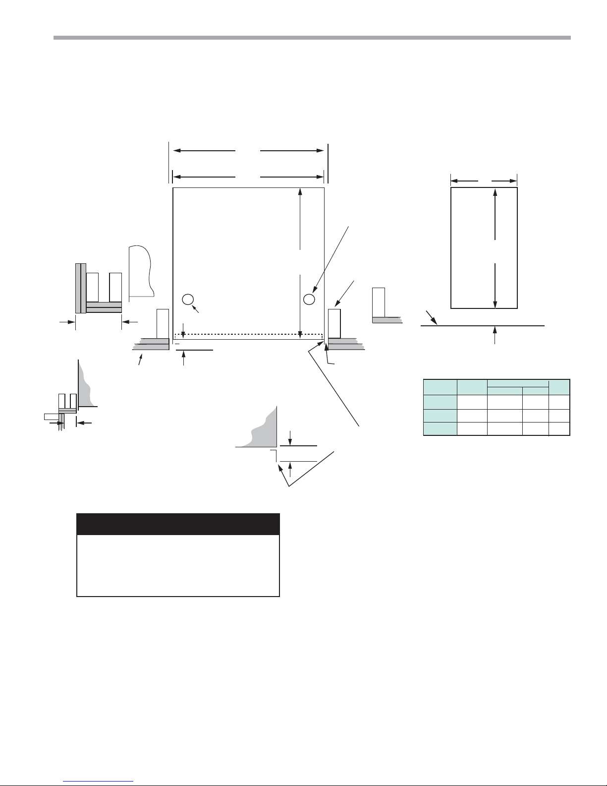
Figure 8
THE SMART SOLUTION FOR ENERGY EFFICIENCY
Vertical Stack
Rev.: 04/24/2019
Typical Cabinet with G Return Air Panel Installation
C
R.O.
A
C
X X
Note 4
OUTSIDE
CORNER
X
X
X
Note
4
INSIDE
CORNER
X
5/8” (16) drywall 1
or 2 layers. Position
studs accordingly.
TSL CABINET
REMOTE
MOUNTED
THERMOSTAT
TOP VIEW
Low Voltage Conduit
1-3/8” (35) min - Note 7
to 2 3/8” (60) max from cabinet
to front of finished wall
1.25 (32)
High Voltage
FRONT
VIEW
57 1/2
B
2 x 4
nominal
studs
X
seal gap
(4) sides
Cabinet Flange
(4) sides
1 Layer
X
Floor
Model
09-12
15-18
24-36
(1460)
5 7/8
(149)
Note 6
Drywall Opening
A
17
[432]17[432]20[508]
19.25
[489]
24.25
[610]
B
Heat Pump Hybrid
19
[483]
24
[610]
22
[559]
27
[686]
C
17.25
[438]
19.5
[495]
24.5
[622]
NOTICE!
Seal between studs and cabinet fl anges
with weather tight foam material to
prevent wall cavity air from infi ltrating unit
or room.
1. All dimensions are in inches (mm).
2. Cabinet confi guration will determine slab core
3. Recommend stud walls surrounding cabinet.
4. Return air panel (not shown) overlaps rough
5. Installer supplied top duct should connect with
6. If cabinet stand or ISO pad is used add to
7. For 2"(50) fi lter set cabinet 2"(50) minimum
climatemaster.com
drilling location and walls surrounding cabinet.
Drywall and studs should not be attached or
contacting cabinet for best sound attenuation.
Where possible fi ll gaps with sound absorbing
material. Use iso pad under cabinet. Secure
cabinet to fl oor in two places at back.
opening, allow minimum of 3 1/2" (89) dry wall
to corner. Do not caulk G panel to wall.
fl ex boot.
dimension.
from front of drywall.
19
CLIMATEMASTER WATER-SOURCE HEAT PUMPS
e
l
a
P
r
m
-
t
(
TSL Vertical Stack
Rev.: 04/24/2019
Typical Cabinet with G Panel Installation - Flush Air Frame
6.00
(152)
Note 8, 9
X
Seal Gap (4) Sides
B
CABINET
TOP VIEW
ѥ NOTICE! ѥ
Recessed cabinet requires frame kit.
Outside air requires motorized damper
or pre-treated air Above 45°F (7°C).
between the frame and cabinet with
Seal
weather seal material to avoid air being pulled
A
in from the wall cavity.Attach frame to studs
not cabinet.
Do not distort frame shim sides if required.
Frame
Outside
Drywall
G Style
Return Air Panel
Frame
Crossbars
(Note 4)
X
3-1/2
(89)
It is recommended to leave 2” (51) minimum clearance
on both sides for removing panel
1
“G” Frame
12-1/4
(311)
28-5/8
(727)
Floor
* Dimension if cabinet is on floor.
Add if cabinet is on stand/pad.
Notes
1. Cabinet conƂguration will determine slab coredrilling location and walls surrounding cabinet.
.38
(10)
R.O.
FRONT VIEW
XX
DRYWALL
5/8"
(16)
9.00 x 2.00 KO (228 x 51)
Outside air opening,
left or right side
to suit installation.
24.12
(612)
(120)
4.75
C
57-1/2
(1460) R.O.
5-7/8*
(149)
Cabinet
Flange
1.25 (32)
Kit Size
48A0100N
48A0100N51
48A0100N52
2
Cross bars
09-12
15-18
24-36
Kit Part
Frame Kit
17.00
(432)
19.25
(489)
24.25
(616)
Note 5
2
BA
17.00
(432)
19
(483)
24
(610)
Optional Damper Motor
(Order seperately) 48A0100N04 may be
installed on left or right side. Note 7
short wire harness to be installed in electric box,
remove ko in box cover, snap in molex.
Description
Qty
1
2
Frame1
Cross Bar
Panel
C
(400)
(498)
(620)
D
18.50
(470)
21.50
(546)
25.50
(648)
59
(1599)
4.50
* (114)
16-5/8
19-5/8
24-3/8
D
Front View
Frame Installed
G Panel
Perimet
Crossb
Third Pai
Tabs fro
4 Pane
Mounting
Nuts (1/4
Lowest
of Tabs
2. Recommend stud walls surrounding cabinet. Drywall and studs should not be attached or contacting cabinet for best
sound attenuation. Where possible Ƃll gaps with sound absorbing material. Use iso pad under cabinet. Secure cabinet
ƃoor in two places atback.
3. Return air panel overlaps rough opening, allow minimum of 3 1/2" (89) dry wall to corner. Do not caulk panel to wall.
4. G Panel attaches to frame cross bars. Cabinet must be recessed behind wall.
5. Bend out 4 tabs per side on frame. Position cross bars behind ears, attach with 8 screws.
6. For Ƃlter access, pivot inner panel, open Ƃlter access snap. For chassis removal, remove G Panel, remove 2 cross bars,
remove Ƃlter panel, slideout chassis.
7. When untreated outside air is required, 48A0100N04 motorized damper must be used, mixed air temperature
must be no lower than 45°F (7°C), no higher than 95 DB/75 WB, and not exceed 20% of total CFM. Contractor
must supply air duct, cut hole in stud, remove K.O., assemble and wire damper assembly.
Note: Use extreme weather temperatures.
8. For 2" wlter set cabinet 6.25"
158) from front of drywall.
20
ClimateMaster Water-Source Heat Pumps
THE SMART SOLUTION FOR ENERGY EFFICIENCY
Vertical Stack
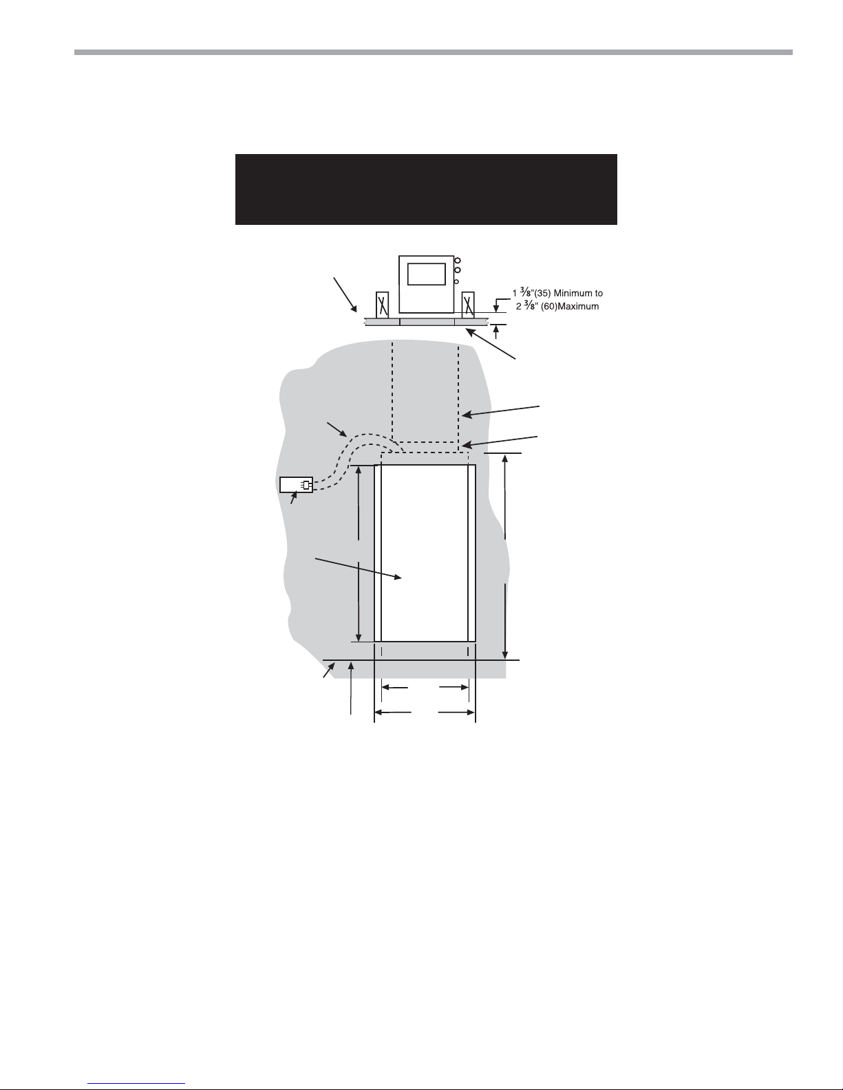
Rev.: 04/24/2019
NOTICE - Drywall openings shown below are for specifi c
cabinets as indicated. Cut openings for your cabinet
and thermostat.
One or two layers
of drywall. Set
studs accordingly.
Finished Wall
(Notes 1 and 3)
Note 2
Opening for
“G” Panel
15' Whip
Slab
5⁄”
(622)
57½”
(1461)
24.25”
(616)
24
½”
(622)
Cabinet
Figure 10
Supply Air
Ductwork
(Customer Supplied)
Canvas Type
Flex Boot
(Customer
Supplied)
65”
(1650)
Cabinet
for D5G0RAE115E010C and G Return Air Panel
Notes:
1. Optional factory-installed whips (Model Digit 13) end with 9 pin molex connector.
2. Field-supplied 2x4 Box must be a type that the side can be removed so molex can be put inside. Position box
horizontal or vertical for thermostat.
3. Optional 15, 25, or 35 foot whips (thermostat cable Class 2) available. Whips in BX armor available as special.
4. 1” to 12”(25 to 305) stands available, stands are bulk shipped and must be fi eld installed.
5. When stands are used, make sure riser length and position is calculated correctly. Stand pads raises everything up.
6. For 2” fi lter, set cabinet 2” (50) minimum from front of drywall.
Drywall Openings
climatemaster.com
21
 Loading...