

ClimateMaster TSD 006, TSD 036, TSD 012, TSD 009, TSD 030 Installation Operation & Maintenance
...
Tranquility®
20
(TS) Series
Models TSD/H/V 006 - 070
60Hz - HFC-410A
INSTALLATION, OPERATION
& MAINTENANCE
97B0075N06
Revised: 17 June, 2015
Model Nomenclature - General Overview 3
General Information 4
Unit Physical Data 6
Horizontal Installation 7
Field Conversion of Air Discharge 9
Horizontal Installation 10
Vertical Installation 11
Piping Installation 13
Water-Loop Heat Pump Applications 14
Ground-Loop Heat Pump Applications 15
Ground-Water Heat Pump Applications 17
Water Quality Standards 19
Electrical - Line Voltage 20
Electrical - Power Wiring 26
Electrical - Power & Low Voltage Wiring 27
Electrical - Low Voltage Wiring 28
Electrical - Thermostat Wiring 29
TS Blower Performance Data - (ECM Motor) Standard Unit - No Reheat 30
TS Blower Performance Data - Standard Unit No Reheat (PSC Motor) 31
TS Blower Performance Data - Units with
ClimaDry
ECM Blower Control 33
Typical Wiring Diagram - Units with CXM Board
and ECM Fan Motor (Single Phase) 35
Typical Wiring Diagram - Units with CXM Board
and PSC Fan Motor (Single Phase) 36
CXM Controls 39
DXM Controls 40
Safety Features - CXM and DXM Controls 42
ClimaDry
Piping System Cleaning and Flushing 47
Unit and System Checkout 49
Unit Start-Up Procedure 50
Unit Operating Conditions 52
ClimaDry
(When Operating in Non-ClimaDry
Preventive Maintenance 57
Functional Troubleshooting 58
Performance Troubleshooting 59
Start-Up Log Sheet 60
Functional Troubleshooting 61
Warranty (U.S. & Canada) 62
Warranty (International) 63
Revision History 64
®
(PSC Motor) 32
®
Modulating Reheat Option 44
®
II Option Corrections
®
Mode) 52

CLIMATEMASTER WATER-SOURCE HEAT PUMPS
®
Tranquility
Rev.: 06/17/15
20 (TS) Series
This Page Intentionally Left Blank
2
ClimateMaster Water-Source Heat Pumps
THE SMART SOLUTION FOR ENERGY EFFICIENCY
®
Tranquility
20 (TS) Series
Rev.: 06/17/15
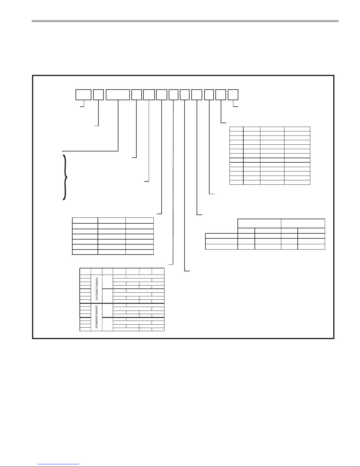
Model Nomenclature - General Overview
Model Type
TS = Tranquility
Single Stage Scroll
(Rotary: Size 006-012)
Configuration
V = Vertical Upflow
D = Vertical Downflow
Unit Size
006 - E,G
009 - E,G
012 - E,G
018 - E,G
024 - E,F,G,H
030 - E,F,G,H
036 - E,F,G,H
042 - E,F,G,H,N
048 - E,F,G,H,N
060 - E,F,G,H,N
070 - F,G,H,N
1 2
TS
®
20
H = Horizontal
3
V
4 5 6 7
A0 2 4 CG 3 0 C L T
Revision Level
A = Current Revision Sizes 006-012
B = Current Revision Sizes 018
C = Current Revision Sizes 024-070
AVAILABLE
VOLTAGES
Voltage
G = 208/230/60/1
E = 265/60/1
H = 208/230/60/3
F = 460/60/3
N = 575/60/3
Controls
Control w/o Disconnect w/ Disconnect
CXM
DXM
CXM w/LON
DXM w/LON
CXM w/MPC
DXM w/MPC
OPTION
RANGE
1
A
J
K
2
C
L
M
3
E
N
P
4
G
R
S
ULTRA
QUIET
NO
YES
NO
YES
C
D
L
M
N
P
1” FILTER
RAIL
YES
NO
YES
NO
YES
NO
YES
NO
2” FILTER
NO
NO
NO
NO
RAIL
YES
YES
YES
YES
NO
NO
NO
NO
A
B
E
K
R
S
1” FILTER
FRAME
NO
YES
NO
YES
NO
YES
NO
YES
91011121314
8
Cabinet
2” FILTER
NO
NO
NO
NO
FRAME
YES
NO
YES
NO
YES
NO
YES
NO
Water Circuit Options
0 = None
2 = HWG (Coil Only)
5 = Secondary Circulating Pump
6 = HWG (Coil Only) w/Auto Flow Regulator 2.5 GPM/T on
7 = HWG (Coil Only) w/Auto Flow Regulator 3.0 GPM/T on
8 = Auto Flow Regulator 2.5 GPM/Ton
9 = Auto Flow Regulator 3.0 GPM/Ton
15
S
Standard
S = Standard
Supply Air & Motor Option
Option Supply Configuration Motor
T
Top
D
Down
B
Back
S Straight TSH PSC
Top
V TSV PSC Hi Static
*
Down
UTSD
*
Back
YTSH
*
Straight
ZTSH
*
K TSV ECM
Top
*
N TSD ECM
Down
*
P TSH ECM
Back
*
W TSH ECM
Straight
*
* N/A for Sizes 006-012
Return Air
L = Left Return
R = Right Return
Heat Exchanger Options
Non Coated Air Coil
Copper Cupro-Nickel Copper Cupro-Nickel
Standard
®
Reheat
ClimaDry
Motorized Valve
ClimaDry® reheat coil not coated
*Microchannel On Sizes 024-048
C
E
TSUW
TSV
TSD
TSH
Tin Plated Air Coil /
Microchannel Air Coil*
N
P
PSC
PSC
PSC
PSC Hi Static
PSC Hi Static
PSC Hi Static
A
D
J
F
Note: Above model nomenclature is a general reference. Consult individual engineering guides for detailed information.
ClimaDry® II Option Notes:
1. Unit must have DXM control option. 460 volt unit units require a four wire power supply with neutral.
2. ClimaDry® II may not be combined with motorized water valve, internal secondary circulating pump, or automatic
fl ow regulator options.
3. Unit minimum entering air temperature while in the dehumidifi cation, cooling, or continuous fan modes is
65ºF DB/55ºF WB. Operation below this minimum may result in nuisance faults.
4. A thermostat with dehumidifi cation mode or thermostat and separate humidistat/dehumidistat is required for
activation and control of ClimaDry® II.
5. Downfl ow and 575 volt units are not eligible for ClimaDry® II.
climatemaster.com
3
CLIMATEMASTER WATER-SOURCE HEAT PUMPS
®
Tranquility
Rev.: 06/17/15
20 (TS) Series
General Information
Safety
Warnings, cautions, and notices appear throughout this
manual. Read these items carefully before attempting any
installation, service, or troubleshooting of the equipment.
DANGER: Indicates an immediate hazardous situation,
which if not avoided will result in death or serious injury.
DANGER labels on unit access panels must be observed.
WARNING: Indicates a potentially hazardous situation,
which if not avoided could result in death or serious injury.
CAUTION: Indicates a potentially hazardous situation or
an unsafe practice, which if not avoided could result in
minor or moderate injury or product or property damage.
NOTICE: Notifi cation of installation, operation, or
maintenance information, which is important, but which is
not hazard-related.
WARNING!
WARNING! The EarthPure® Application and Service Manual
should be read and understood before attempting to service
refrigerant circuits with HFC-410A.
WARNING!
WARNING! To avoid the release of refrigerant into the
atmosphere, the refrigerant circuit of this unit must be
serviced only by technicians who meet local, state, and
federal profi ciency requirements.
WARNING! All refrigerant discharged from this unit must
be recovered WITHOUT EXCEPTION. Technicians must
follow industry accepted guidelines and all local, state, and
federal statutes for the recovery and disposal of refrigerants.
If a compressor is removed from this unit, refrigerant circuit
oil will remain in the compressor. To avoid leakage of
compressor oil, refrigerant lines of the compressor must be
sealed after it is removed.
Inspection - Upon receipt of the equipment, carefully
check the shipment against the bill of lading. Make sure
all units have been received. Inspect the packaging of
each unit, and inspect each unit for damage. Ensure that
the carrier makes proper notation of any shortages or
damage on all copies of the freight bill and completes a
common carrier inspection report. Concealed damage
not discovered during unloading must be reported to the
carrier within 15 days of receipt of shipment. If not fi led
within 15 days, the freight company can deny the claim
without recourse.
Note: It is the responsibility of the purchaser to fi le all
necessary claims with the carrier. Notify your equipment
supplier of all damage within fi fteen (15) days of
shipment.
Storage - Equipment should be stored in its original
packaging in a clean, dry area. Store units in an upright
position at all times. Stack units a maximum of 3 units
high.
WARNING!
CAUTION!
CAUTION! To avoid equipment damage, DO NOT use
these units as a source of heating or cooling during the
construction process. The mechanical components and fi lters
will quickly become clogged with construction dirt and debris,
which may cause system damage.
WARNING!
WARNING! The installation of water-source heat pumps and
all associated components, parts, and accessories which
make up the installation shall be in accordance with the
regulations of ALL authorities having jurisdiction and MUST
conform to all applicable codes. It is the responsibility of
the installing contractor to determine and comply with ALL
applicable codes and regulations.
Unit Protection - Cover units on the job site with either
the original packaging or an equivalent protective
covering. Cap the open ends of pipes stored on the
job site. In areas where painting, plastering, and/or
spraying has not been completed, all due precautions
must be taken to avoid physical damage to the units
and contamination by foreign material. Physical damage
and contamination may prevent proper start-up and may
result in costly equipment clean-up.
Examine all pipes, fi ttings, and valves before installing
any of the system components. Remove any dirt or debris
found in or on these components.
4
ClimateMaster Water-Source Heat Pumps

THE SMART SOLUTION FOR ENERGY EFFICIENCY
Pre-Installation - Installation, Operation, and
Maintenance instructions are provided with each unit.
Horizontal equipment is designed for installation
above false ceiling or in a ceiling plenum. Other unit
confi gurations are typically installed in a mechanical
room. The installation site chosen should include
adequate service clearance around the unit. Before unit
start-up, read all manuals and become familiar with the
unit and its operation. Thoroughly check the system
before operation.
®
Tranquility
20 (TS) Series
Rev.: 06/17/15
General Information
CAUTION!
CAUTION! All three phase scroll compressors must have
direction of rotation verifi ed at start-up. Verifi cation is
achieved by checking compressor Amp draw. Amp draw
will be substantially lower compared to nameplate values.
Additionally, reverse rotation results in an elevated sound
level compared to correct rotation. Reverse rotation will result
in compressor internal overload trip within several minutes.
Verify compressor type before proceeding.
Prepare units for installation as follows:
1. Compare the electrical data on the unit nameplate
with ordering and shipping information to verify that
the correct unit has been shipped.
2. Keep the cabinet covered with the original packaging
until installation is complete and all plastering,
painting, etc. is fi nished.
3. Verify refrigerant tubing is free of kinks or dents and
that it does not touch other unit components.
4. Inspect all electrical connections. Connections must
be clean and tight at the terminals.
5. Remove any blower support packaging (water-to-air
units only).
6. Loosen compressor bolts on units equipped with
compressor spring vibration isolation until the
compressor rides freely on the springs. Remove
shipping restraints. (No action is required for
compressors with rubber grommets.)
7. Some airfl ow patterns are fi eld convertible (horizontal
units only). Locate the airfl ow conversion section of
this IOM.
8. Locate and verify any hot water generator (HWG),
hanger, or other accessory kit located in the
compressor section or blower section.
CAUTION!
CAUTION! DO NOT store or install units in corrosive
environments or in locations subject to temperature or
humidity extremes (e.g., attics, garages, rooftops, etc.).
Corrosive conditions and high temperature or humidity can
signifi cantly reduce performance, reliability, and service life.
Always move and store units in an upright position. Tilting
units on their sides may cause equipment damage.
CAUTION!
CAUTION! CUT HAZARD - Failure to follow this caution may
result in personal injury. Sheet metal parts may have sharp
edges or burrs. Use care and wear appropriate protective
clothing, safety glasses and gloves when handling parts and
servicing heat pumps.
NOTICE! Failure to remove shipping brackets from
spring-mounted compressors will cause excessive
noise, and could cause component failure due to
added vibration.
climatemaster.com
5

CLIMATEMASTER WATER-SOURCE HEAT PUMPS
®
Tranquility
20 (TS) Series
Rev.: 06/17/15
Unit Physical Data
Tranquility®
20 Single-Stage (TS) Series (60Hz)
Model 006 009 012 018 024 030 036 042 048 060 070
Compressor (1 Each)
Factory Charge HFC-410A
(oz) [kg]
24 [0.68] 32 [0.91] 34 [0.96] 50 [1.13] 41 [1.16] 41 [1.16] 48 [1.36] 68 [1.93] 68 [1.93] 136 [3.86] 141 [4.0]
Rotary Scroll
ECM Fan Motor & Blower
Blower Wheel Size (dia x w) (in) [mm]
N/A N/A N/A
9 x 7
[229 x 178]
9 x 7
[229 x 178]
9 x 7
[229 x 178]
11 x 10
[279 x 254]
11 x 10
[279 x 254]
11 x 10
[279 x 254]
11 x 10
[279 x 254]
[279 x 254]
PSC Fan Motor & Blower (3 Speeds)
Blower Wheel Size (dia x w) (in) [mm]
6 X 5
[152 X 127]
6 X 5
[152 X 127]
6 X 5
[152 X 127]
9 x 7
[229 x 178]
9 x 7
[229 x 178]
9 x 7
[229 x 178]
10 x 10
[254 x 254]
10 x 10
[254 x 254]
10 x 10
[254 x 254]
11 x 10
[279 x 254]
[279 x 254]
Water Connection Size
FPT (in)
1/2” 1/2” 1/2” 3/4” 3/4” 3/4” 3/4” 1” 1” 1” 1”
HWG Connection Size
FPT (in)
N/A N/A N/A 1/2” 1/2” 1/2” 1/2” 1/2” 1/2” 1/2” 1/2”
Coax Volume
Volume (US Gallons) [liters]
0.17 [0.64] 0.29 [1.10] 0.45 [1.70] 0.56 [2.12] 0.76 [2.88] 0.76 [2.88] 0.92 [3.48] 1.24 [4.69] 1.24 [4.69] 1.56 [5.91] 1.56 [5.91]
Vertical Upfl ow/Downfl ow
Air Coil Dimensions (h x w) (in) [mm]
Standard Filter - 1” [25.4mm]
Throwaway, qty (in) [mm]
Weight - Operating, (lbs) [kg]
Weight - Packaged, (lbs) [kg]
16 x 16
[406 x 406]
Upfl ow Only
16 x 20
[406 x 508]
136 [62] 156 [71] 160 [73] 257 [117] 266 [121] 268 [122] 327 [148] 414 [188] 416 [189] 441 [200] 443 [201]
146 [66] 166 [75] 170 [77] 267 [121] 276 [125] 278 [126] 337 [153] 424 [192] 426 [193] 451 [205] 453 [205]
16 x 16
[406 x 406]
Upfl ow Only
16 x 20
[406 x 508]
16 x 16
[406 x 406]
Upfl ow Only
16 x 20
[406 x 508]
24 x 20
[610 x 508]
24 x 24
[610 x 610]
28 x 20
[711 x 508]
28 x 24
[711 x 610]
28 x 20
[711 x 508]
28 x 24
[711 x 610]
28 x 25
[711 x 635]
28 x 30
[711 x 762]
32 x 25
[813 x 635]
2 - 16 x 30
[2 - 406 x 762]
32 x 25
[813 x 635]
2 - 16 x 30
[2 - 406 x 762]
36 x 25
[914 x 635]
1 - 16 x 30;
1 - 20 x 30
[1 - 406 x 762;
1 - 508 x 762]
[914 x 635]
1 - 16 x 30;
1 - 20 x 30
[1 - 406 x 762;
1 - 508 x 762]
Horizontal
Air Coil Dimensions (h x w ) (in) [mm]
Standard Filter - 1” [25.4mm]
Throwaway, qty (in) [mm]
Weight - Operating, (lbs) [kg]
Weight - Packaged, (lbs) [kg]
16 x 16
[406 x 406]
16 x 20
[406 x 508]
136 [62] 156 [71] 160 [73] 257 [117] 266 [121] 268 [122] 327 [148] 414 [188] 416 [189] 441 [200] 443 [201]
146 [66] 166 [75] 170 [77] 267 [121] 276 [125] 278 [126] 337 [153] 424 [192] 426 [193] 451 [205] 453 [205]
16 x 16
[406 x 406]
16 x 20
[406 x 508]
16 x 16
[406 x 406]
16 x 20
[406 x 508]
18 x 27
[457 x 686]
2 - 18 x 18
[2 - 457 x 457]
18 x 31
[457 x 787]
2 - 18 x 18
[2 - 457 x 457]
18 x 31
[457 x 787]
2 - 18 x 18
[2 - 457 x 457]
20 x 35
[508 x 889]
1 - 12 x 20;
1- 20 x 25
[1 - 305 x 508;
1 - 508 x 635]
20 x 40
[508 x 1016]
1 - 18 x 20;
1 - 20 x 24
[1 - 457 x 508;
1 - 508 x 610]
20 x 40
[508 x 1016]
1 - 18 x 20;
1 - 20 x 24
[1 - 457 x 508;
1 - 508 x 610]
20 x 45
[508 x 1143]
2 - 20 x 24
[2 - 508 x 610]
[508 x 1143]
2 - 20 x 24
[2 - 508 x 610]
Notes:
All units have TXV expansion device and 1/2” & 3/4” electrical knockouts.
575 volt motors are two speed.
For units with ClimaDry
®
II option add 66lbs (30kg) to weights.
11 x 10
11 x 10
36 x 25
20 x 45
Unit Maximum Water Working Pressure
Options
Base Unit
Internal Secondary Pump (ISP)
®
ClimaDry
Internal Motorized Water Valve (MWV)
Internal Auto Flow Valve
Max Pressure PSIG [kPa]
500 [3,447]
145 [999]
145 [999]
300 [2,068]
300 [2,068]
Use the lowest maximum pressure rating when multiple options are combined.
6
ClimateMaster Water-Source Heat Pumps
THE SMART SOLUTION FOR ENERGY EFFICIENCY
®
Tranquility
20 (TS) Series
Rev.: 06/17/15
Horizontal Installation
Horizontal Unit Location
Units are not designed for outdoor installation. Locate
the unit in an INDOOR area that allows enough space
for service personnel to perform typical maintenance or
repairs without removing unit from the ceiling. Horizontal
units are typically installed above a false ceiling or in a
ceiling plenum. Never install units in areas subject to
freezing or where humidity levels could cause cabinet
condensation (such as unconditioned spaces subject
to 100% outside air). Consideration should be given to
access for easy removal of the fi lter and access panels.
Provide suffi cient room to make water, electrical, and
duct connection(s).
If the unit is located in a confi ned space, such as a closet,
provisions must be made for return air to freely enter the
space by means of a louvered door, etc. Any access panel
screws that would be diffi cult to remove after the unit
is installed should be removed prior to setting the unit.
Refer to Figure 3 for an illustration of a typical installation.
Refer to unit submittal data or engineering design guide
for dimensional data.
Conform to the following guidelines when selecting
unit location:
1. Provide a hinged access door in concealed-spline
or plaster ceilings. Provide removable ceiling
tiles in T-bar or lay-in ceilings. Refer to horizontal
unit dimensions for specifi c series and model in
unit submittal data. Size the access opening to
accommodate the service technician during the
removal or replacement of the compressor and the
removal or installation of the unit itself.
2. Provide access to hanger brackets, water valves and
fi ttings. Provide screwdriver clearance to access
panels, discharge collars and all electrical connections.
3. DO NOT obstruct the space beneath the unit with
piping, electrical cables and other items that prohibit
future removal of components or the unit itself.
4. Use a manual portable jack/lift to lift and support the
weight of the unit during installation and servicing.
The installation of water source heat pump units and all
associated components, parts and accessories which
make up the installation shall be in accordance with
the regulations of ALL authorities having jurisdiction
and MUST conform to all applicable codes. It is the
responsibility of the installing contractor to determine
and comply with ALL applicable codes and regulations.
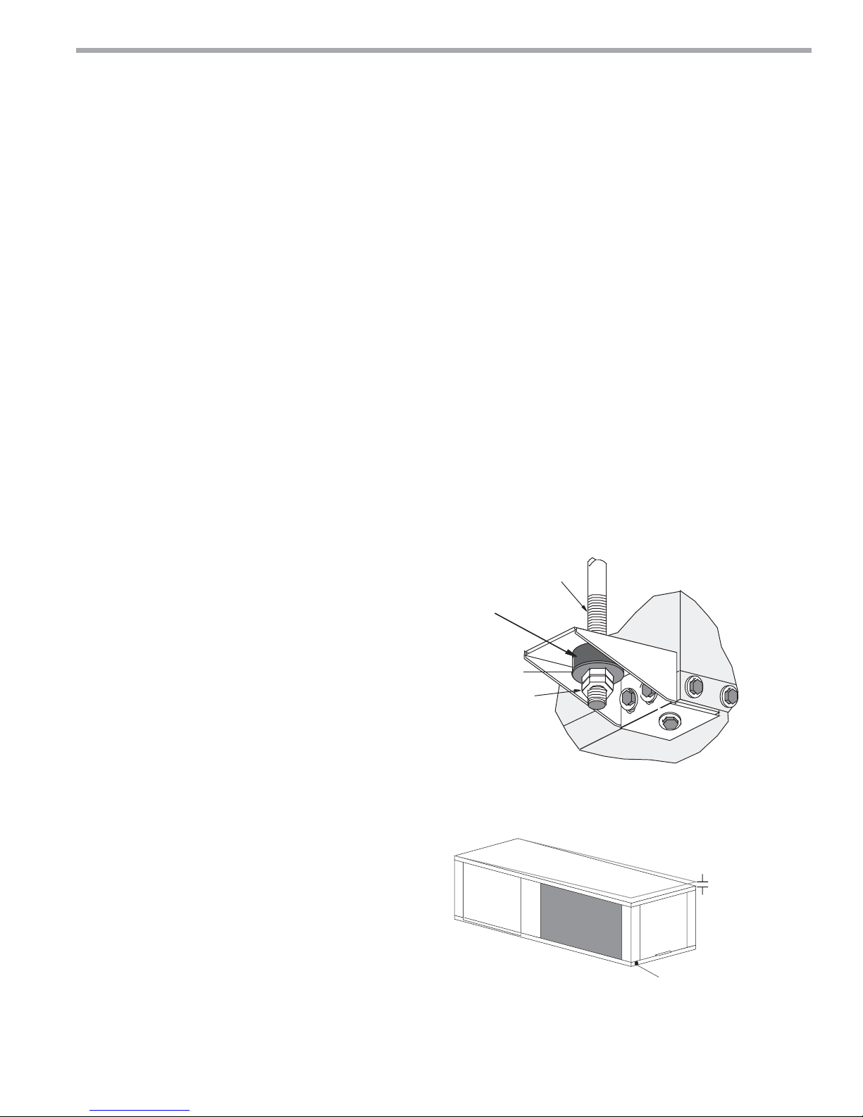
Mounting Horizontal Units
Horizontal units have hanger kits pre-installed from the
factory as shown in Figure 1. Figure 3 shows a typical
horizontal unit installation.
Horizontal heat pumps are typically suspended above
a ceiling or within a soffi t using fi eld supplied, threaded
rods sized to support the weight of the unit.
Use four (4) fi eld supplied threaded rods and factory
provided vibration isolators to suspend the unit. Hang
the unit clear of the fl oor slab above and support the
unit by the mounting bracket assemblies only. DO NOT
attach the unit fl ush with the fl oor slab above.
Pitch the unit toward the drain as shown in Figure 2 to
improve the condensate drainage. On small units (less
than 2.5 tons/8.8kW) ensure that unit pitch does not
cause condensate leaks inside the cabinet.
Figure 1: Hanger Bracket
>PP@7KUHDGHG
5RGE\RWKHUV
9LEUDWLRQ,VRODWRU
IDFWRU\VXSSOLHG
:DVKHU
E\RWKHUV
'RXEOH+H[1XWV
E\RWKHUV
Figure 2: Horizontal Unit Pitch
1/4” (6.4mm) pitch
toward drain for drainage
Drain
Connection
climatemaster.com
7
CLIMATEMASTER WATER-SOURCE HEAT PUMPS
®
Tranquility
Rev.: 06/17/15
20 (TS) Series
Horizontal Installation
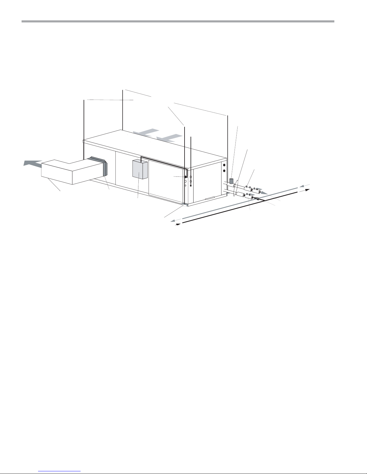
Figure 3: Typical Horizontal Unit Installation
>PP@WKUHDGHGURGV
E\RWKHUV
5HWXUQ$LU
3RZHU:LULQJ
6XSSO\$LU
8QLW3RZHU
,QVXODWHGVXSSO\GXFWZLWK
DWOHDVWRQHGHJHOERZ
WRUHGXFHDLUQRLVH
)OH[LEOH'XFW
&RQQHFWRU
8QLW3RZHU
'LVFRQQHFW
E\RWKHUV
8QLW+DQJHU
Air Coil - To obtain maximum performance, the air coil
should be cleaned before start-up. A 10% solution of
dishwasher detergent and water is recommended for
both sides of the coil. A thorough water rinse should
follow. UV based anti-bacterial systems may damage
coated air coils.
2SWLRQDO/RZ3UHVVXUH'URS:DWHU
7KHUPRVWDW
:LULQJ
&RQWURO9DOYH
FDQEHLQWHUQDOO\PRXQWHG
RQVRPHPRGHOV
6WDLQOHVVVWHHOEUDLGKRVH
ZLWKLQWHJUDO- VZLYHO
2SWLRQDO%DODQFLQJ9DOYH
:DWHU,Q
%DOO9DOYHZLWKRSWLRQDO
LQWHJUDO37SOXJ
%XLOGLQJ
/RRS
:DWHU2XW
Notice! Installation Note - Ducted Return: Many
horizontal WSHPs are installed in a return air ceiling
plenum application (above ceiling). Vertical WSHPs are
commonly installed in a mechanical room with free return
(e.g. louvered door). Therefore, fi lter rails are the industry
standard and are included on ClimateMaster commercial
heat pumps for the purposes of holding the fi lter only.
For ducted return applications, the fi lter rail must be
removed and replaced with a duct fl ange or fi lter frame.
Canvas or fl exible connectors should also be used to
minimize vibration between the unit and ductwork.
8
ClimateMaster Water-Source Heat Pumps
THE SMART SOLUTION FOR ENERGY EFFICIENCY
Water
Connection End
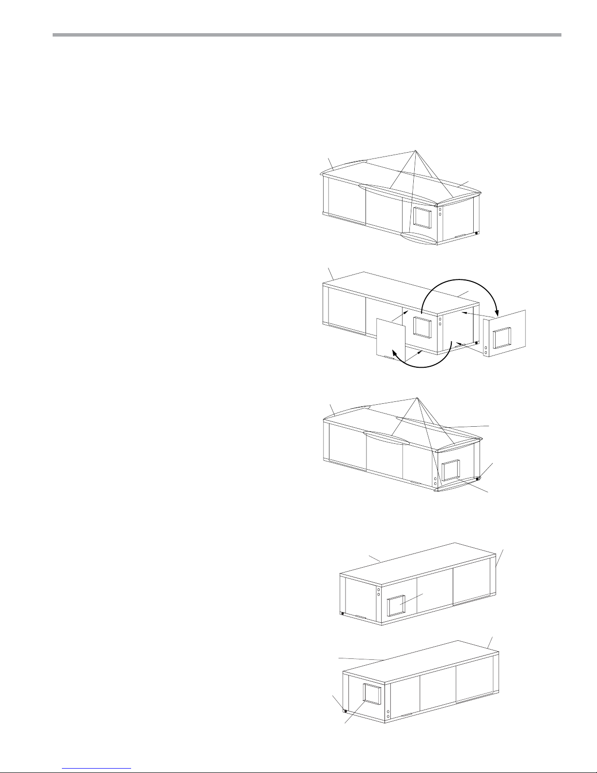
Return Air
Remove Screws
Water
Connection End
Return Air
Rotate
Move to Side
Side Discharge
Return Air
Water
Connection End
Discharge Air
Drain
Back Discharge
Replace Screws
®
Tranquility
20 (TS) Series
Rev.: 06/17/15
Field Conversion of Air Discharge
Overview - Horizontal units can be fi eld converted
between side (straight) and back (end) discharge using
the instructions below.
Note: It is not possible to fi eld convert return air
between left or right return models due to the
necessity of refrigeration copper piping changes.
Preparation - It is best to fi eld convert the unit on the
ground before hanging. If the unit is already hung it
should be taken down for the fi eld conversion.
Side to Back Discharge Conversion
1. Place unit in well lit area. Remove the screws as shown
in Figure 4 to free top panel and discharge panel.
2. Lift out the access panel and set aside. Lift and rotate
the discharge panel to the other position as shown,
being careful with the blower wiring.
3. Check blower wire routing and connections for
tension or contact with sheet metal edges. Re-route if
necessary.
4. Check refrigerant tubing for contact with other
components.
5. Reinstall top panel and screws noting that the location
for some screws will have changed.
6. Manually spin the fan wheel to ensure that the wheel
is not rubbing or obstructed.
7. Replace access panels.
Figure 4: Left Return Side to Back
Back to Side Discharge Conversion - If the discharge is
changed from back to side, use above instruction noting
that illustrations will be reversed.
Left vs. Right Return - It is not possible to fi eld convert
return air between left or right return models due to
the necessity of refrigeration copper piping changes.
However, the conversion process of side to back or
back to side discharge for either right or left return
confi guration is the same. In some cases, it may be
possible to rotate the entire unit 180 degrees if the return
air connection needs to be on the opposite side. Note
that rotating the unit will move the piping to the
other end of the unit.
Figure 5: Right Return Side to Back
Return Air
Supply Duct
Side Discharge
Return Air
Drain
Discharge Air
Back Discharge
Water
Connection End
Water
Connection End
climatemaster.com
9
CLIMATEMASTER WATER-SOURCE HEAT PUMPS
Condensate Piping
06/17/15
n
®
Tranquility
Rev.: 06/17/15
ev.:
20 (TS) Series
Duct System Installatio
Horizontal Installation
Condensate Piping - Horizontal Units - A condensate
drain line must be installed and pitched away for the unit
to allow for proper drainage. This connection must meet
all local plumbing/building codes.
Pitch the unit toward the drain as shown in Figure 2 to
improve the condensate drainage. On small units (less
than 2.5 tons/8.8 kW), ensure that unit pitch does not
cause condensate leaks inside the cabinet.
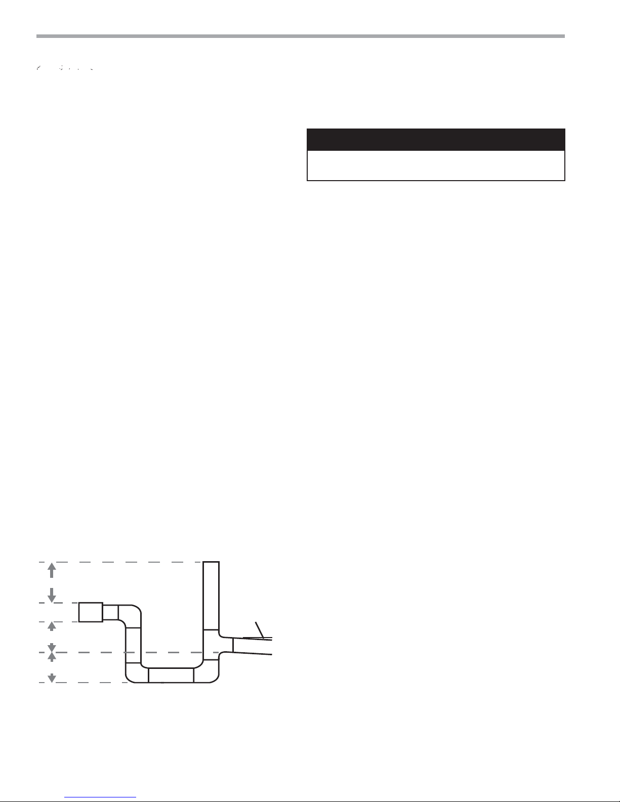
Install condensate trap at each unit with the top of
the trap positioned below the unit condensate drain
connection as shown in Figure 6. Design the depth of
the trap (water-seal) based upon the amount of ESP
capability of the blower (where 2 inches [51mm] of ESP
capability requires 2 inches [51mm] of trap depth).
As a general rule, 1-1/2 inch [38mm] trap depth is the
minimum.
Each unit must be installed with its own individual trap
and connection to the condensate line (main) or riser.
Provide a means to fl ush or blow out the condensate line.
DO NOT install units with a common trap and/or vent.
Always vent the condensate line when dirt or air
can collect in the line or a long horizontal drain line
is required. Also vent when large units are working
against higher external static pressure than other units
connected to the same condensate main since this may
cause poor drainage for all units on the line. WHEN A
VENT IS INSTALLED IN THE DRAIN LINE, IT MUST BE
LOCATED AFTER THE TRAP IN THE DIRECTION OF
THE CONDENSATE FLOW.
Figure 6: Horizontal Condensate Connection
ರ
CAUTION! Ensure condensate line is pitched toward drain
1/8” per ft [11mm per m] of run.
Duct System Installation - Proper duct sizing and design
is critical to the performance of the unit. The duct system
should be designed to allow adequate and even airfl ow
through the unit during operation. Air fl ow through
the unit MUST be at or above the minimum stated
airfl ow for the unit to avoid equipment damage. Duct
systems should be designed for quiet operation. Refer
to Figure 3 for horizontal duct system details or Figure
8 for vertical duct system details. A fl exible connector
is recommended for both discharge and return air duct
connections on metal duct systems to eliminate the
transfer of vibration to the duct system. To maximize
sound attenuation of the unit blower, the supply and
return plenums should include internal fi berglass duct
liner or be constructed from ductboard for the fi rst few
feet. Application of the unit to uninsulated ductwork in an
unconditioned space is not recommended, as the unit’s
performance may be adversely affected.
At least one 90° elbow should be included in the supply
duct to reduce air noise. If air noise or excessive air fl ow is
a problem, the blower speed can be changed. For airfl ow
charts, consult submittal data for the series and model of
the specifi c unit.
If the unit is connected to existing ductwork, a previous
check should have been made to ensure that the
ductwork has the capacity to handle the airfl ow required
for the unit. If ducting is too small, as in the replacement
of a heating only system, larger ductwork should be
installed. All existing ductwork should be checked for
leaks and repaired as necessary.
CAUTION!
ರ
ರ
* Some units include a painted drain connection.
Using a threaded pipe or similar device to clear
any excess paint accumulated inside this fitting
may ease final drain line installation.
10
ರ3HU
)RRW
ClimateMaster Water-Source Heat Pumps
THE SMART SOLUTION FOR ENERGY EFFICIENCY
Flexible canvas duct
connector to reduce
noise and vibration
Use turning vanes in
supply transition
Internally insulate return
transition duct to reduce
noise
Rev.: 2/13
Internally insulate supply
GXFWIRUWKHILUVW·P
each way to reduce noise
Rounded return
transition
Remove supply duct
flanges from inside blower
compartment and install
on supply air opening of
unit. Do not use a supply
air plenum/duct smaller
than the size of the supply
duct flanges.
®
Tranquility
20 (TS) Series
Rev.: 06/17/15
Vertical Installation
Vertical Unit Location - Units are not designed for
outdoor installation. Locate the unit in an INDOOR
area that allows enough space for service personnel to
perform typical maintenance or repairs without removing
unit from the mechanical room/closet. Vertical units
are typically installed in a mechanical room or closet.
Never install units in areas subject to freezing or where
humidity levels could cause cabinet condensation (such
as unconditioned spaces subject to 100% outside air).
Consideration should be given to access for easy removal
of the fi lter and access panels. Provide suffi cient room to
make water, electrical, and duct connection(s).
If the unit is located in a confi ned space, such as a closet,
provisions must be made for return air to freely enter
the space by means of a louvered door, etc. Any access
panel screws that would be diffi cult to remove after
the unit is installed should be removed prior to setting
the unit. Refer to Figures 7 and 8 for typical installation
illustrations. Refer to unit submittal data or engineering
design guide for dimensional data.
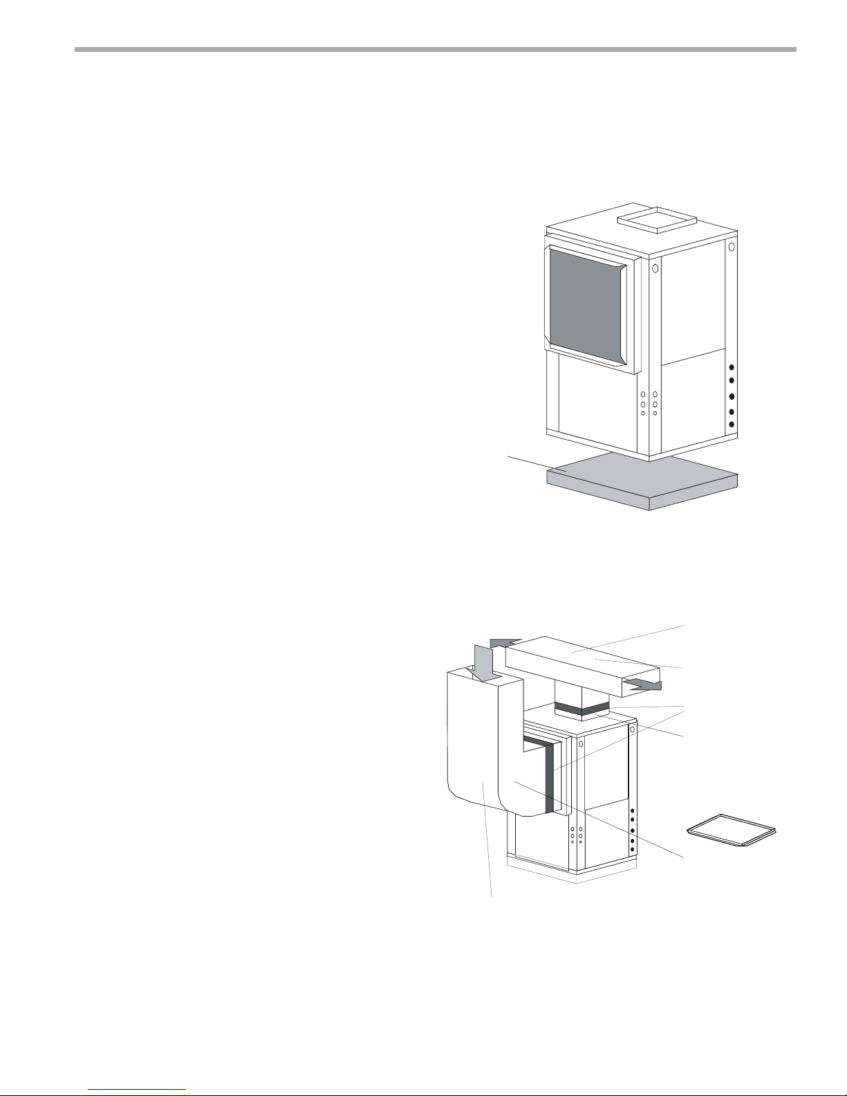
1. Install the unit on a piece of rubber, neoprene or
other mounting pad material for sound isolation. The
pad should be at least 3/8” [10mm] to 1/2” [13mm] in
thickness. Extend the pad beyond all four edges of
the unit.
2. Provide adequate clearance for fi lter replacement
and drain pan cleaning. Do not block fi lter access
with piping, conduit or other materials. Refer to
unit submittal data or engineering design guide for
dimensional data.
3. Provide access for fan and fan motor maintenance
and for servicing the compressor and coils without
removing the unit.
4. Provide an unobstructed path to the unit within the
closet or mechanical room. Space should be suffi cient
to allow removal of the unit, if necessary.
5. Provide access to water valves and fi ttings and
screwdriver access to the unit side panels, discharge
collar and all electrical connections.
Figure 7: Vertical Unit Mounting
$LU3DGRUH[WUXGHG
SRO\VW\UHQHLQVXODWLRQERDUG
Figure 8: Typical Vertical Unit Installation Using
Ducted Return Air
Notice! Installation Note - Ducted Return: Many
horizontal WSHPs are installed in a return air ceiling
plenum application (above ceiling). Vertical WSHPs are
commonly installed in a mechanical room with free return
(e.g. louvered door). Therefore, fi lter rails are the industry
standard and are included on ClimateMaster commercial
heat pumps for the purposes of holding the fi lter only.
For ducted return applications, the fi lter rail must be
removed and replaced with a duct fl ange or fi lter frame.
Canvas or fl exible connectors should also be used to
minimize vibration between the unit and ductwork.
climatemaster.com
11
CLIMATEMASTER WATER-SOURCE HEAT PUMPS
®
Tranquility
Rev.: 06/17/15
20 (TS) Series
Vertical Installation
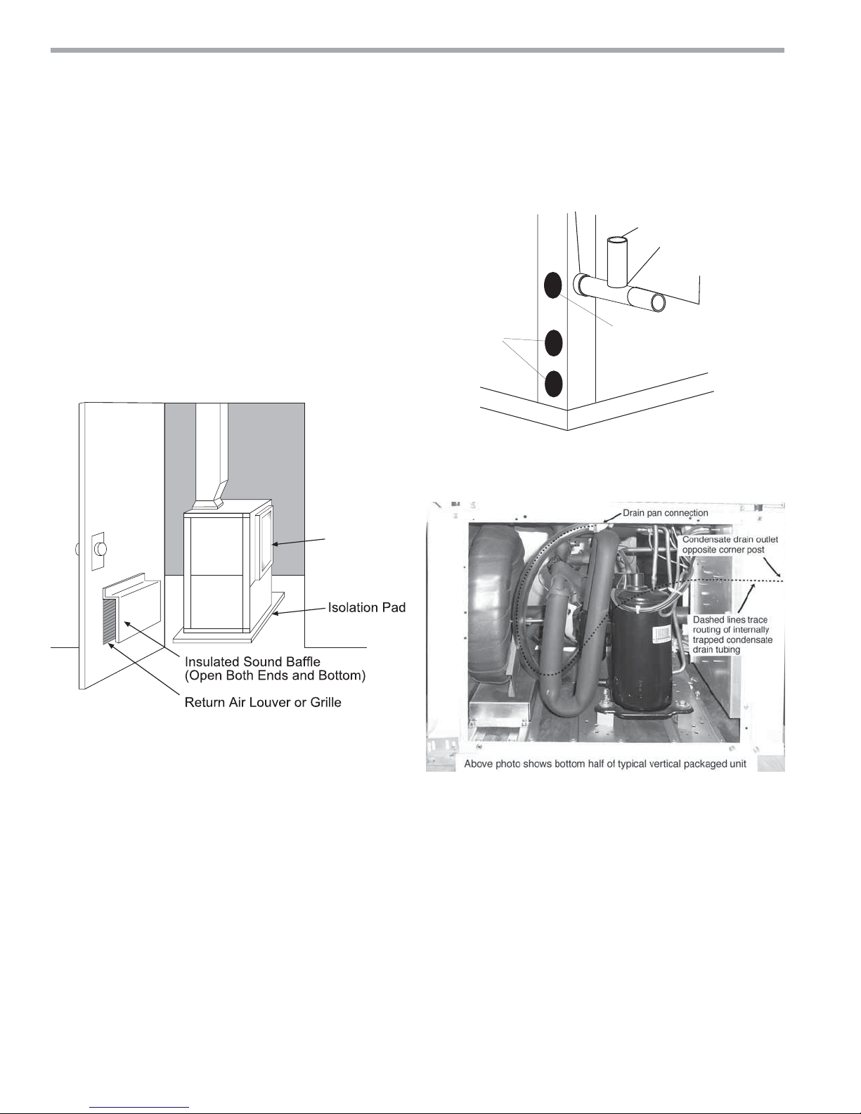
Sound Attenuation for Vertical Units - Sound
attenuation is achieved by enclosing the unit within a
small mechanical room or a closet. Additional measures
for sound control include the following:
1. Mount the unit so that the return air inlet is 90° to the
return air grille. Refer to Figure 9. Install a sound baffl e
as illustrated to reduce line-of sight sound transmitted
through return air grilles.
2. Mount the unit on a rubber or neoprene isolation pad
to minimize vibration transmission to the building
structure.
Figure 9: Vertical Sound Attenuation
Return
Air Inlet
Figure 10a: Vertical Condensate Drain
*3/4" FPT
Vent
3/4" PVC
1/8" per foot
slope to drain
Water
Connections
* Some units include a painted drain connection. Using a
threaded pipe or similar device to clear any excess paint
accumulated inside this fitting may ease final drain line installation.
Alternate
Condensate
Location
Figure 10b: Vertical Internal Condensate Trap
Notice! Units with clear plastic drain lines should have
regular maintenance (as required) to avoid buildup of
debris, especially in new construction.
Condensate Piping for Vertical Units - A condensate
line must be installed and pitched away from the unit to
allow for proper drainage. This connection must meet
all local plumbing/building codes. Vertical units utilize
a condensate hose inside the cabinet as a trapping
loop; therefore an external trap is not necessary. Figure
10a shows typical condensate connections. Figure 10b
illustrates the internal trap for a typical vertical heat
pump. Each unit must be installed with its own individual
vent (where necessary) and a means to fl ush or blow
out the condensate drain line. Do not install units with a
common trap and/or vent.
12
ClimateMaster Water-Source Heat Pumps
THE SMART SOLUTION FOR ENERGY EFFICIENCY
®
Tranquility
20 (TS) Series
Rev.: 06/17/15
Piping Installation
Installation of Supply and Return Piping
Follow these piping guidelines.
1. Install a drain valve at the base of each supply and
return riser to facilitate system fl ushing.
2. Install shut-off / balancing valves and unions at each
unit to permit unit removal for servicing.
3. Place strainers at the inlet of each system circulating
pump.
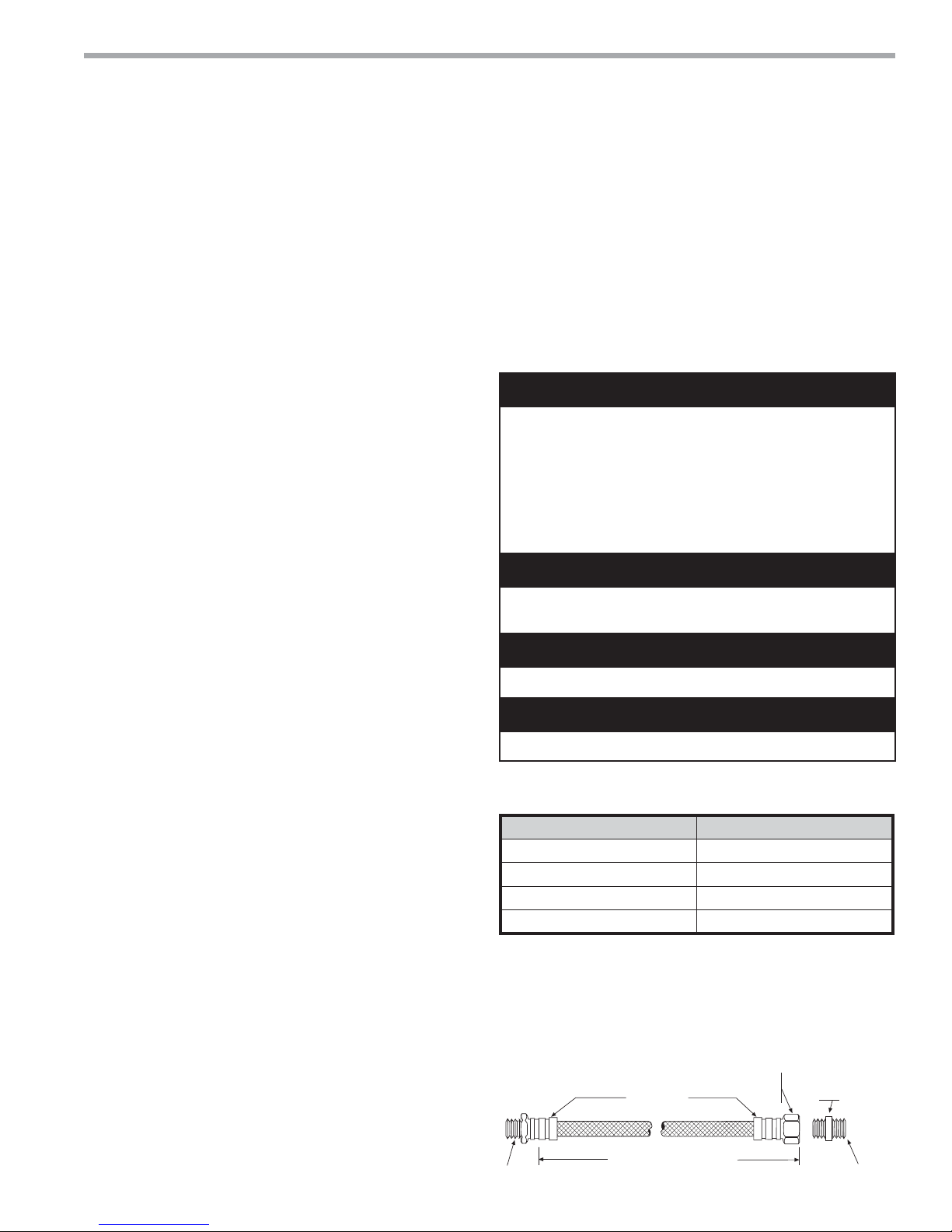
4. Select the proper hose length to allow slack between
connection points. Hoses may vary in length by +2%
to -4% under pressure.
5. Refer to Table 1. Do not exceed the minimum bend
radius for the hose selected. Exceeding the minimum
bend radius may cause the hose to collapse, which
reduces water fl ow rate. Install an angle adapter to
avoid sharp bends in the hose when the radius falls
below the required minimum.
Insulation is not required on loop water piping except
where the piping runs through unheated areas, outside
the building or when the loop water temperature is
below the minimum expected dew point of the pipe
ambient conditions. Insulation is required if loop water
temperature drops below the dew point (insulation is
required for ground loop applications in most climates).
Pipe joint compound is not necessary when Tefl on
®
thread tape is pre-applied to hose assemblies or when
fl ared-end connections are used. If pipe joint compound
is preferred, use compound only in small amounts on
the external pipe threads of the fi tting adapters. Prevent
sealant from reaching the fl ared surfaces of the joint.
Note: When antifreeze is used in the loop, ensure that
®
it is compatible with the Tefl on
tape or pipe joint
compound that is applied.
Maximum allowable torque for brass fi ttings is 30 ft-lbs
[41 N-m]. If a torque wrench is not available, tighten
fi nger-tight plus one quarter turn. Tighten steel fi ttings
as necessary.
Optional pressure-rated hose assemblies designed
specifi cally for use with ClimateMaster units are available.
Similar hoses can be obtained from alternate suppliers.
Supply and return hoses are fi tted with swivel-joint fi ttings
at one end to prevent kinking during installation.
Refer to Figure 11 for an illustration of a typical supply/
return hose kit. Adapters secure hose assemblies to the
unit and risers. Install hose assemblies properly and check
regularly to avoid system failure and reduced service life.
Installer Caution: After making water connections on
units equipped with ClimaDry
®
, ensure the three union
nuts on the internal three-way water valve are tight.
ClimaDry®-equipped units have a manual air bleed valve
at the top of the reheat coil. This valve must be used to
bleed the air from the reheat coil after fi lling the system,
for the ClimaDry® to operate properly.
WARNING!
WARNING! Polyolester Oil, commonly known as POE oil, is
a synthetic oil used in many refrigeration systems including
those with HFC-410A refrigerant. POE oil, if it ever comes
in contact with PVC or CPVC piping, may cause failure of
the PVC/CPVC. PVC/CPVC piping should never be used
as supply or return water piping with water source heat
pump products containing HFC-410A as system failures and
property damage may result.
CAUTION!
CAUTION! Corrosive system water requires corrosion
resistant fi ttings and hoses, and may require water treatment.
CAUTION!
CAUTION! Do not bend or kink supply lines or hoses.
CAUTION!
CAUTION! Piping must comply with all applicable codes.
Table 1: Metal Hose Minimum Bend Radii
Hose Diameter Minimum Bend Radii
1/2" [12.7mm] 2-1/2" [6.4cm]
3/4" [19.1mm] 4" [10.2cm]
1" [25.4mm] 5-1/2" [14cm]
1-1/4" [31.8mm] 6-3/4" [17.1cm]
NOTICE! Do not allow hoses to rest against structural
building components. Compressor vibration may
be transmitted through the hoses to the structure,
causing unnecessary noise complaints.
Figure 11: Supply/Return Hose Kit
Rib Crimped
Length
MPT
(2 ft [0.6m] Length Standard)
Swivel
Brass
Fitting
Brass
Fitting
MPT
climatemaster.com
13
CLIMATEMASTER WATER-SOURCE HEAT PUMPS
®
Tranquility
Rev.: 06/17/15
20 (TS) Series
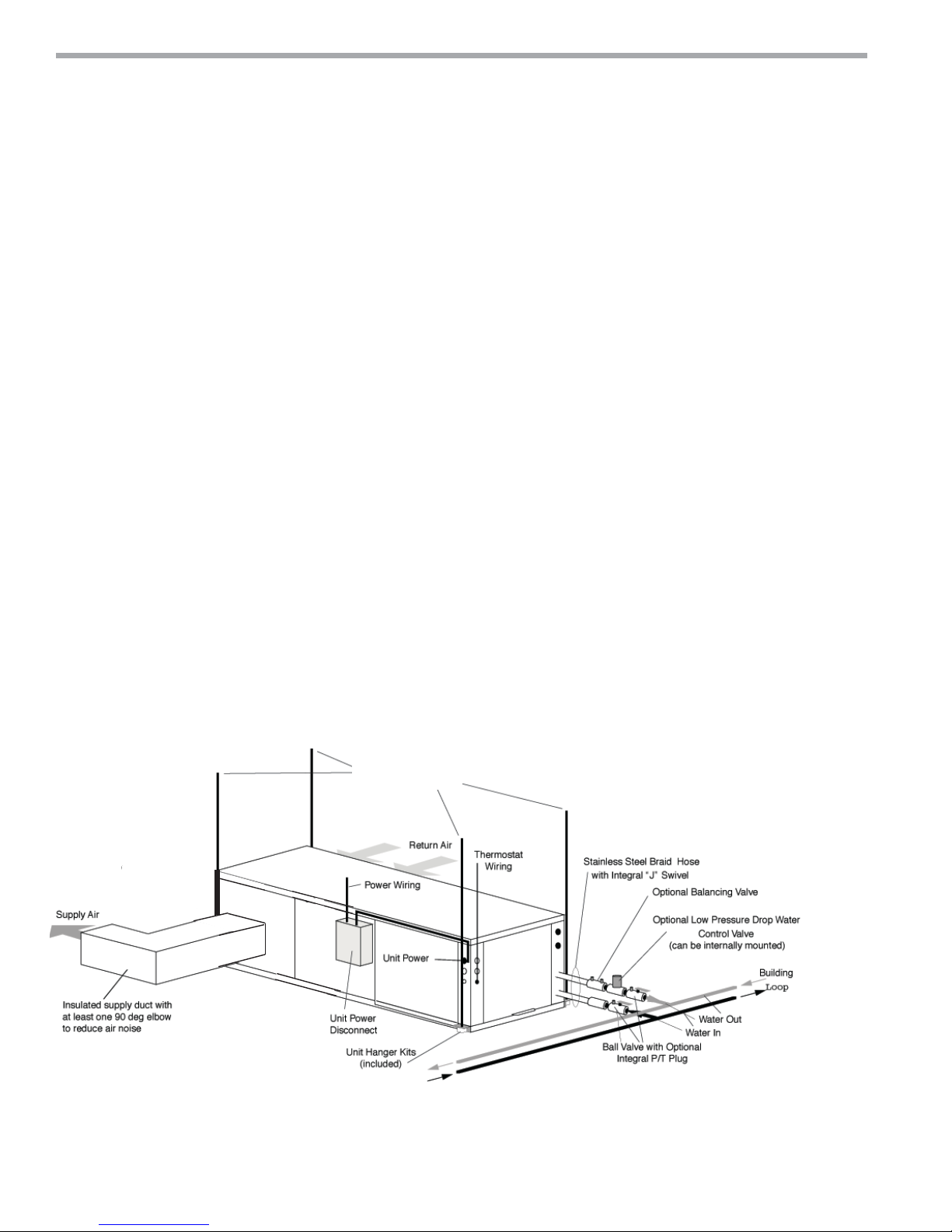
Water-Loop Heat Pump Applications
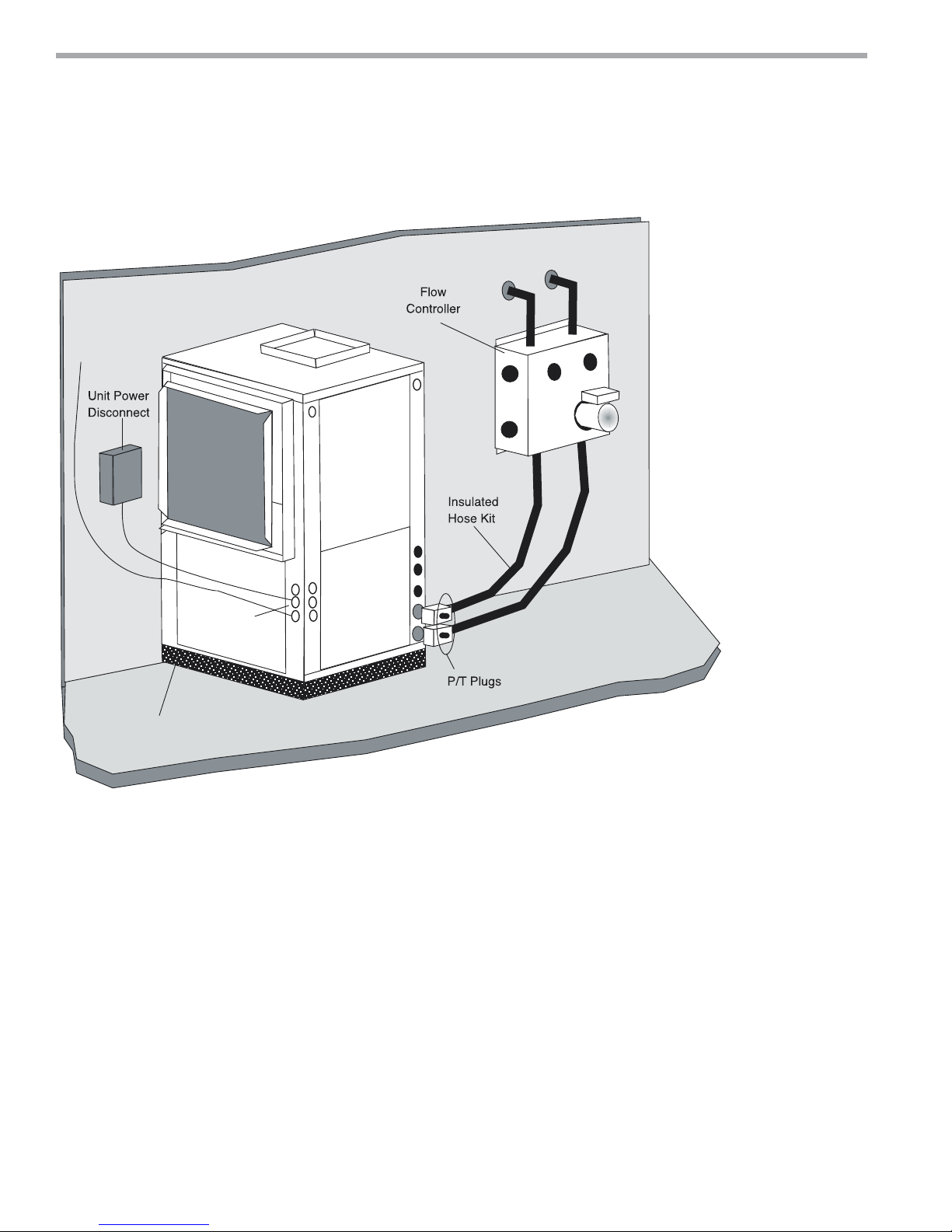
Commercial Water Loop Applications
Commercial systems typically include a number of
units connected to a common piping system. Any unit
plumbing maintenance work can introduce air into the
piping system; therefore air elimination equipment
is a major portion of the mechanical room plumbing.
Consideration should be given to insulating the
piping surfaces to avoid condensation. ClimateMaster
recommends unit insulation any time the water
temperature is expected to be below 60ºF (15.6ºC).
Metal to plastic threaded joints should never be used due
to their tendency to leak over time.
®
Tefl on
tape thread sealant is recommended to
minimize internal fouling of the heat exchanger. Do
not over tighten connections and route piping so as
not to interfere with service or maintenance access.
Hose kits are available from ClimateMaster in different
confi gurations as shown in Figure 12 for connection
between the unit and the piping system. Depending
upon selection, hose kits may include shut off valves,
P/T plugs for performance measurement, high pressure
stainless steel braided hose, “Y” type strainer with
blow down valve, and/or “J” type swivel connection.
Balancing valves and an external low pressure drop
solenoid valve for use in variable speed pumping
systems may also be included in the hose kit.
The piping system should be fl ushed to remove dirt,
piping chips, and other foreign material prior to
operation (see “Piping System Cleaning and Flushing
Procedures” in this manual). The fl ow rate is usually set
between 2.25 and 3.5 gpm per ton [2.9 and 4.5 l/m per
kW] of cooling capacity. ClimateMaster recommends 3
gpm per ton [3.9 l/m per kW] for most applications of
water loop heat pumps. To ensure proper maintenance
and servicing, P/T ports are imperative for temperature
and fl ow verifi cation, as well as performance checks.
Water loop heat pump (cooling tower/boiler) systems
typically utilize a common loop, maintained between
60 - 90°F [16 - 32°C]. The use of a closed circuit evaporative
cooling tower with a secondary heat exchanger between
the tower and the water loop is recommended. If an
open type cooling tower is used continuously, chemical
treatment and fi ltering will be necessary.
Figure 12: Typical Water-Loop Application
3/8" [10mm] threaded rods
(by others)
Low Water Temperature Cutout Setting - CXM Control
When antifreeze is selected, the LT1 jumper (JW3) should be clipped to select the low temperature (antifreeze
10.0°F [-12.2°C]) setpoint and avoid nuisance faults (see “Low Water Temperature Cutout Selection” in this manual).
Note: Low water temperature operation requires extended range equipment.
14
ClimateMaster Water-Source Heat Pumps
THE SMART SOLUTION FOR ENERGY EFFICIENCY
®
Tranquility
20 (TS) Series
Rev.: 06/17/15
Ground-Loop Heat Pump Applications
CAUTION!
CAUTION! The following instructions represent industry
accepted installation practices for closed loop earth coupled
heat pump systems. Instructions are provided to assist the
contractor in installing trouble free ground loops. These
instructions are recommendations only. State/provincial
and local codes MUST be followed and installation MUST
conform to ALL applicable codes. It is the responsibility of
the installing contractor to determine and comply with ALL
applicable codes and regulations.
CAUTION!
CAUTION! Ground loop applications require extended range
equipment and optional refrigerant/water circuit insulation.
Pre-Installation
Prior to installation, locate and mark all existing
underground utilities, piping, etc. Install loops for new
construction before sidewalks, patios, driveways, and other
construction has begun. During construction, accurately
mark all ground loop piping on the plot plan as an aid in
avoiding potential future damage to the installation.
Piping Installation
The typical closed loop ground source system is shown in
Figure 13. All earth loop piping materials should be limited
to polyethylene fusion only for in-ground sections of the
loop. Galvanized or steel fi ttings should not be used at any
time due to their tendency to corrode. All plastic to metal
threaded fi ttings should be avoided due to their potential
to leak in earth coupled applications. A fl anged fi tting
should be substituted. P/T plugs should be used so that
fl ow can be measured using the pressure drop of the unit
heat exchanger.
Earth loop temperatures can range between 25 and 110°F
[-4 to 43°C]. Flow rates between 2.25 and 3 gpm [2.41 to
3.23 l/m per kW] of cooling capacity is recommended in
these applications.
Test individual horizontal loop circuits before backfi lling.
Test vertical U-bends and pond loop assemblies prior to
installation. Pressures of at least 100 psi [689 kPa] should
be used when testing. Do not exceed the pipe pressure
rating. Test entire system when all loops are assembled.
Flushing the Earth Loop
Upon completion of system installation and testing, fl ush
the system to remove all foreign objects and purge to
remove all air.
Antifreeze
I
n areas where minimum entering loop temperatures
drop below 40°F [5°C] or where piping will be routed
through areas subject to freezing, antifreeze is required.
Alcohols and glycols are commonly used as antifreeze;
however your local sales offi ce should be consulted to
determine the antifreeze best suited to your area. Freeze
protection should be maintained to 15°F [9°C] below
the lowest expected entering loop temperature. For
example, if 30°F [-1°C] is the minimum expected entering
loop temperature, the leaving loop temperature would
be 22 to 25°F [-6 to -4°C] and freeze protection should be
at 15°F [-10°C]. Calculation is as follows:
30°F - 15°F = 15°F [-1°C - 9°C = -10°C].
All alcohols should be premixed and pumped from
a reservoir outside of the building when possible or
introduced under the water level to prevent fumes.
Calculate the total volume of fl uid in the piping system.
Then use the percentage by volume shown in table
2 for the amount of antifreeze needed. Antifreeze
concentration should be checked from a well mixed
sample using a hydrometer to measure specifi c gravity.
Low Water Temperature Cutout Setting - CXM Control
When antifreeze is selected, the LT1 jumper (JW3) should
be clipped to select the low temperature (antifreeze
10.0°F [-12.2°C]) setpoint and avoid nuisance faults (see
“Low Water Temperature Cutout Selection” in this
manual). Note: Low water temperature operation
requires extended range equipment.
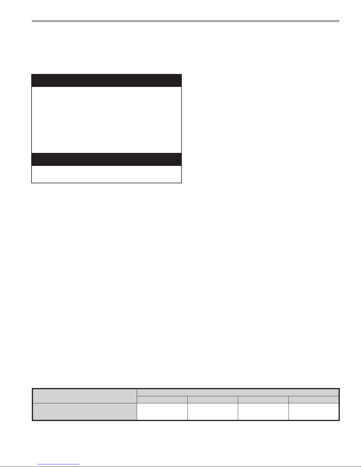
Table 2: Antifreeze Percentages by Volume
Type
Methanol
100% USP food grade Propylene Glycol
Ethanol*
* Must not be denatured with any petroleum based product
Minimum Temperature for Low Temperature Protection
10°F [-12.2°C] 15°F [-9.4°C] 20°F [-6.7°C] 25°F [-3.9°C]
25%
38%
29%
climatemaster.com
21%
25%
25%
16%
22%
20%
10%
15%
14%
15
CLIMATEMASTER WATER-SOURCE HEAT PUMPS
High and
Low Voltage
Knockouts
Vibration Isolation Pad
To Thermostat
®
Tranquility
Rev.: 06/17/15
20 (TS) Series
Ground-Loop Heat Pump Applications
Figure 13: Typical Ground-Loop Application
16
ClimateMaster Water-Source Heat Pumps

THE SMART SOLUTION FOR ENERGY EFFICIENCY
®
Tranquility
20 (TS) Series
Rev.: 06/17/15
Ground-Water Heat Pump Applications
Open Loop - Ground Water Systems - Typical open
loop piping is shown in Figure 14. Shut off valves should
be included for ease of servicing. Boiler drains or other
valves should be “tee’d” into the lines to allow acid
fl ushing of the heat exchanger. Shut off valves should be
positioned to allow fl ow through the coax via the boiler
drains without allowing fl ow into the piping system.
P/T plugs should be used so that pressure drop and
temperature can be measured.
Supply and return water
piping materials should be limited to copper, PE, or similar
material. PVC or CPVC should never be used as they are
incompatible with the POE oils used in HFC-410A products
and piping system failure and property damage may result.
WARNING!
WARNING! Polyolester Oil, commonly known as POE oil, is
a synthetic oil used in many refrigeration systems including
those with HFC-410A refrigerant. POE oil, if it ever comes
in contact with PVC or CPVC piping, may cause failure of
the PVC/CPVC. PVC/CPVC piping should never be used
as supply or return water piping with water source heat
pump products containing HFC-410A as system failures and
property damage may result.
Water quantity should be plentiful and of good quality.
Consult table 3 for water quality guidelines. The unit can
be ordered with either a copper or cupro-nickel water
heat exchanger. Consult Table 3 for recommendations.
Copper is recommended for closed loop systems and
open loop ground water systems that are not high
in mineral content or corrosiveness. In conditions
anticipating heavy scale formation or in brackish water, a
cupro-nickel heat exchanger is recommended. In ground
water situations where scaling could be heavy or where
biological growth such as iron bacteria will be present, an
open loop system is not recommended. Heat exchanger
coils may over time lose heat exchange capabilities due
to build up of mineral deposits. Heat exchangers must
only be serviced by a qualifi ed technician, as acid and
special pumping equipment is required. Desuperheater
coils can likewise become scaled and possibly plugged.
In areas with extremely hard water, the owner should be
informed that the heat exchanger may require occasional
acid fl ushing. In some cases, the desuperheater
option should not be recommended due to hard water
conditions and additional maintenance required.
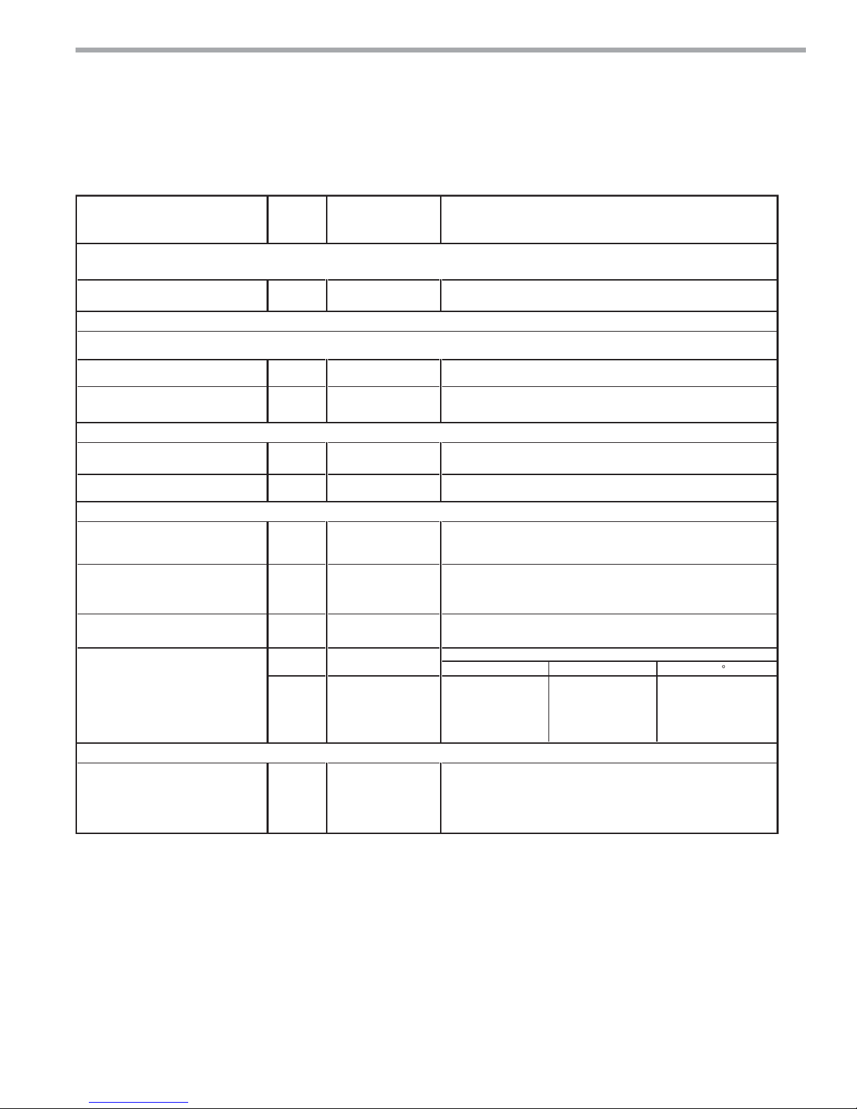
Water Quality Standards - Table 3 should be consulted
for water quality requirements. Scaling potential should
be assessed using the pH/Calcium hardness method.
If the pH <7.5 and the calcium hardness is less than
100 ppm, scaling potential is low. If this method yields
numbers out of range of those listed, the Ryznar Stability
and Langelier Saturation indecies should be calculated.
Use the appropriate scaling surface temperature for the
application, 150°F [66°C] for direct use (well water/open
loop) and DHW (desuperheater); 90°F [32°F] for indirect
use. A monitoring plan should be implemented in these
probable scaling situations. Other water quality issues
such as iron fouling, corrosion prevention and erosion
and clogging should be referenced in Table 3.
Expansion Tank and Pump - Use a closed, bladdertype expansion tank to minimize mineral formation due
to air exposure. The expansion tank should be sized to
provide at least one minute continuous run time of the
pump using its drawdown capacity rating to prevent
pump short cycling. Discharge water from the unit is not
contaminated in any manner and can be disposed of in
various ways, depending on local building codes (e.g.
recharge well, storm sewer, drain fi eld, adjacent stream
or pond, etc.). Most local codes forbid the use of sanitary
sewer for disposal. Consult your local building and
zoning department to assure compliance in your area.
Water Control Valve - Note the placement of the
water control valve in Figure 14. Always maintain water
pressure in the heat exchanger by placing the water
control valve(s) on the discharge line to prevent mineral
precipitation during the off-cycle. Pilot operated slow
closing valves are recommended to reduce water
hammer. If water hammer persists, a mini-expansion
tank can be mounted on the piping to help absorb the
excess hammer shock. Ensure that the total ‘VA’ draw
of the valve can be supplied by the unit transformer.
For instance, a slow closing valve can draw up to 35VA.
This can overload smaller 40 or 50 VA transformers
depending on the other controls in the circuit. A typical
pilot operated solenoid valve draws approximately 15VA
(see Figure 19). Note the special wiring diagrams for slow
closing valves (Figures 20 & 21).
climatemaster.com
17
CLIMATEMASTER WATER-SOURCE HEAT PUMPS
®
Tranquility
Rev.: 06/17/15
20 (TS) Series
Ground-Water Heat Pump Applications
Flow Regulation - Flow regulation can be accomplished
by two methods. One method of fl ow regulation involves
simply adjusting the ball valve or water control valve on
the discharge line. Measure the pressure drop through
the unit heat exchanger, and determine fl ow rate from
Table 9. Since the pressure is constantly varying, two
pressure gauges may be needed. Adjust the valve until
the desired fl ow of 1.5 to 2 gpm per ton [2.0 to 2.6 l/m
per kW] is achieved. A second method of fl ow control
requires a fl ow control device mounted on the outlet of
the water control valve. The device is typically a brass
fi tting with an orifi ce of rubber or plastic material that is
designed to allow a specifi ed fl ow rate. On occasion, fl ow
control devices may produce velocity noise that can be
reduced by applying some back pressure from the ball
valve located on the discharge line. Slightly closing the
valve will spread the pressure drop over both devices,
lessening the velocity noise.
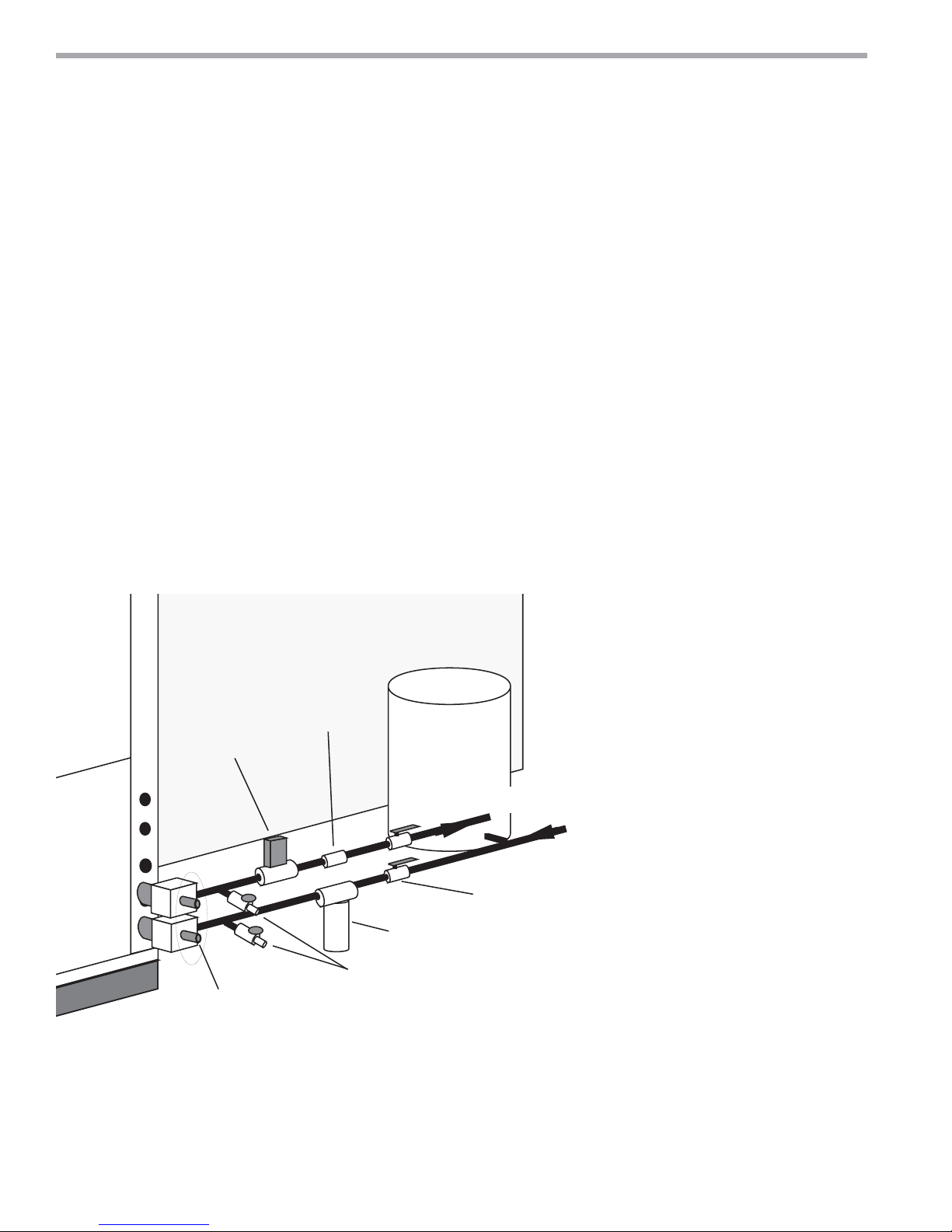
Figure 14: Typical Open Loop/Well Application
Note: When EWT is below 50°F [10°C], 2 gpm per
ton (2.6 l/m per kW) is required.
Water Coil Low Temperature Limit Setting - For all
open loop systems the 30°F [-1.1°C] LT1 setting (factory
setting-water) should be used to avoid freeze damage to
the unit. See “Low Water Temperature Cutout Selection”
in this manual for details on the low limit setting.
Water
Control
Valve
P/T Plugs
Flow
Regulator
Boiler
Drains
Pressure
Tank
Water Out
Water In
Shut-Off
Valve
Optional
Filter
18
ClimateMaster Water-Source Heat Pumps
THE SMART SOLUTION FOR ENERGY EFFICIENCY
Water Quality
Parameter
HX
Material
Closed
Recirculating
Open Loop and Recirculating Well
Scaling Potential - Primary Measurement
pH/Calcium Hardness
All
pH < 7.5 and Ca Hardness <100ppm
Method
Index Limits for Probable Scaling Situations - (Operation outside these limits is not recommended)
Ryznar
All
- 6.0 - 7.5
Stability Index If >7.5 minimize steel pipe use.
Langelier
All
-
-0.5 to +0.5
Saturation Index
If <-0.5 minimize steel pipe use. Based upon 66°C HWG and
Direct well, 29°C Indirect Well HX
Iron Fouling
Iron Fe2+(Ferrous)
All
-
<0.2 ppm (Ferrous)
(Bacterial Iron potential)
If Fe
2+
(ferrous)>0.2 ppm with pH 6 - 8, O2<5 ppm check for iron bacteria.
Iron Fouling
All
-
<0.5 ppm of Oxygen
Above this level deposition will occur.
Corrosion Prevention
pH
All
6 - 8.5
6 - 8.5
Monitor/treat as
needed
Minimize steel pipe below 7 and no open tanks with pH <8
Hydrogen Sulfide (H
2
S)
All
- <0.5 ppm
At H
2
S>0.2 ppm, avoid use of copper and copper nickel piping or HX's.
Rotten egg smell appears at 0.5 ppm level.
Copper alloy (bronze or brass) cast components are OK to <0.5 ppm.
Ammonia ion as hydroxide, chloride,
nitrate and sulfate compounds
All
-
<0.5 ppm
Maximum
Maximum Allowable at maximum water temperature.
Chloride Levels
10$C24$C38
C
Copper
Cupronickel
- <20ppm NR NR
- <150 ppm NR NR
304 S
S - <400 ppm <250 ppm <150 ppm
316 S
S - <1000 ppm <550 ppm < 375 ppm
Titanium - > 1000 ppm >550 ppm >375 ppm
Erosion and Clogging
Particulate Size and
Erosion
All
<10 ppm of particles
and a maximum
velocity of 1.8 m/s
Filtered for maximum
841 micron [0.84 mm,
20 mesh] size.
<10 ppm (<1 ppm "sandfree” for reinjection) of particles and a maximum
velocity of 1.8 m/s. Filtered for maximum 841 micron 0.84 mm,
20 mesh] size. Any particulate that is not removed can potentially
clog components.
Notes:
Rev.: 5/6/2014 S
• NR - Application not recommended.
• "-" No design Maximum.
• Closed Recirculating system is identified by a
closed pressurized piping system.
• Recirculating open wells should observe the open recirculating design considerations.
Above the given limits, scaling is likely to occur. Scaling indexes should be calculated using the limits below
Scaling indexes should be calculated at 66°C for direct use and HWG applications, and at 32°C for indirect HX use.
A monitoring plan should be implemented.
The ClimateMaster Water Quality Table provides water quality requirements for ClimateMaster coaxial heat exchangers. The water should be evaluated by an
independent testing facility comparing to this Table and when properties are outside of these requirements, an external secondary heat exchanger must be used to
isolate the heat pump heat exchanger from the unsuitable water. Failure to do so will void the warranty for the coaxial heat exchanger and any other components
damaged by a leak.
Table 3: Water Quality Standards
Tranquility
Water Quality Standards
®
20 (TS) Series
Rev.: 06/17/15
climatemaster.com
19
CLIMATEMASTER WATER-SOURCE HEAT PUMPS
®
Tranquility
Rev.: 06/17/15
20 (TS) Series
Electrical - Line Voltage
Electrical - Line Voltage - All fi eld installed wiring,
including electrical ground, must comply with the
National Electrical Code as well as all applicable local
codes. Refer to the unit electrical data for fuse sizes.
Consult wiring diagram for fi eld connections that must
be made by the installing (or electrical) contractor. All
fi nal electrical connections must be made with a length
of fl exible conduit to minimize vibration and sound
transmission to the building.
General Line Voltage Wiring - Be sure the available
power is the same voltage and phase shown on the unit
serial plate. Line and low voltage wiring must be done
in accordance with local codes or the National Electric
Code, whichever is applicable.
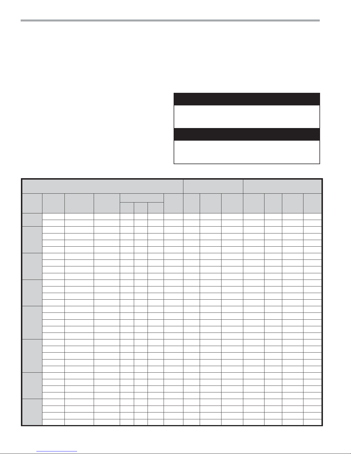
Table 4a: Tranquility® 20 (TS) Series Electrical Data - (PSC Motor & ClimaDry®)
All TS Units with Standard PSC Motor TS Units (PSC)
018
024
030
036
042
048
060
070
Voltage
Code
G 208/230/60/1 197/254 1 9.0 48.0 1.0 10.0 12.3 20 0.8 10.8 13.1 20
E 265/60/1 239/292 1 8.4 40.0 0.9 9.3 11.4 15 0.7 10.0 12.1 20
G 208/230/60/1 197/254 1 13.5 58.3 1.6 15.1 18.5 30 0.8 15.9 19.3 30
E 265/60/1 239/292 1 9 54.0 1.1 10.1 12.4 20 0.7 10.8 13.1 20
H 208/230/60/3 197/254 1 7.1 55.4 1.6 8.7 10.5 15 0.8 9.5 11.3 15
F* 460/60/3* 414/506 1 3.5 28.0 0.9 4.4 5.3 15 0.7 5.1 6.0 15
G 208/230/60/1 197/254 1 12.8 64.0 1.8 14.6 17.8 30 0.8 15.4 18.6 30
E 265/60/1 239/292 1 10.9 60.0 1.4 12.3 15.0 25 0.7 13.0 15.7 25
H 208/230/60/3 197/254 1 8.3 58.0 1.8 10.1 12.2 20 0.8 10.9 13.0 20
F* 460/60/3* 414/506 1 5.1 28.0 1.0 6.1 7.4 15 0.7 6.8 8.1 15
G 208/230/60/1 197/254 1 16.0 77.0 1.8 17.8 21.8 35 0.8 18.6 22.6 35
E 265/60/1 239/292 1 12.2 72.0 2.0 14.2 17.3 25 0.7 14.9 18.0 30
H 208/230/60/3 197/254 1 10 71.0 1.8 11.8 14.3 20 0.8 12.6 15.1 25
F* 460/60/3* 414/506 1 4.7 38.0 1.0 5.7 6.9 15 0.7 6.4 7.6 15
G 208/230/60/1 197/254 1 16.7 79.0 2.2 18.9 23.1 35 0.8 19.7 23.9 40
E 265/60/1 239/292 1 13.5 72.0 1.7 15.2 18.6 30 0.7 15.9 19.3 30
H 208/230/60/3 197/254 1 10.4 73.0 2.2 12.6 15.2 25 0.8 13.4 16.0 25
F* 460/60/3* 414/506 1 5.8 38.0 1.0 6.8 8.3 15 0.7 7.5 9.0 15
N 575/60/3 518/633 1 3.8 36.5 0.8 4.6 5.6 15 N/A N/A N/A N/A
G 208/230/60/1 197/254 1 21.8 117.0 2.7 24.5 30.0 50 1.1 25.6 31.0 50
E 265/60/1 239/292 1 16.3 98.0 2.9 19.2 23.3 35 1.3 20.5 24.6 40
H 208/230/60/3 197/254 1 13.7 83.1 2.7 16.4 19.8 30 1.1 17.5 20.9 30
F* 460/60/3* 414/506 1 6.2 41.0 1.7 7.9 9.5 15 1.3 9.0 10.6 15
N 575/60/3 518/633 1 4.8 33.0 1.4 6.2 7.4 15 N/A N/A N/A N/A
G 208/230/60/1 197/254 1 26.4 134.0 3.8 30.2 36.8 60 1.1 31.3 37.9 60
H 208/230/60/3 197/254 1 16 110.0 3.8 19.8 23.8 35 1.1 20.9 24.9 40
F* 460/60/3* 414/506 1 7.8 52.0 1.3 9.1 11.1 15 1.3 10.4 12.4 20
N 575/60/3 518/633 1 5.7 38.9 2.2 7.9 9.3 15 N/A N/A N/A N/A
G 208/230/60/1 197/254 1 30.8 178.0 4.0 34.8 42.5 70 1.1 35.9 43.6 70
H 208/230/60/3 197/254 1 19.6 138.0 4.0 23.6 28.5 45 1.1 24.7 29.6 45
F* 460/60/3* 414/506 1 8.2 66.1 2.6 10.8 12.9 20 1.3 12.1 14.2 20
N 575/60/3 518/633 1 6.6 55.3 1.5 8.1 9.8 15 N/A N/A N/A N/A
Model
* NEUTRAL CONNECTION REQUIRED! All F Voltage (460 vac) units with ClimaDry
Reheat pump is rated 265 vac and is wired between one hot leg and neutral.
20
Rated
Voltage
Voltage
Min/Max
ClimateMaster Water-Source Heat Pumps
Compressor Fan
QTY RLA LRA
Transformer - All 208/230 voltage units are factory wired
for 208 volt. If supply voltage is 230 volt, installer must
rewire transformer. See wire diagram for connections.
WARNING!
WARNING! To avoid possible injury or death due to electrical
shock, open the power supply disconnect switch and secure
it in an open position during installation.
CAUTION!
CAUTION! Use only copper conductors for fi eld installed
electrical wiring. Unit terminals are not designed to accept
other types of conductors.
Motor
Total
FLA
Unit
FLA
®
require a four wire power supply with neutral.
Min
Circuit
Amp
Max
Fuse/
HACR
TS Units with PSC Fan Motor
and ClimaDry
Reheat
Pump
FLA
Total
Unit
FLA
®
Min
Circuit
Amp
Max
Fuse/
HACR
 Loading...