

ClimateMaster CCE07 Series, CCE12 Series, CCE15 Series, CCE19 Series, TRC09 Series Installation, Operation & Maintenance Instructions Manual
...
Console (CCE) Series
Tranquility Console
(TRC) Series
Commercial Console
Water-Source Heat Pumps
50Hz & 60Hz
Installation, Operation &
Maintenance Instructions
97B0035N01
Revision: 5 Nov., 2009B
Table of Contents
Model Nomenclature 3-4
General Information 5
Storage 6
Pre-Installation 6
Physical Data 7-9
Installation 10
Condensate Piping 11
Piping Connection 12-14
Piping Installation 15
Water-Loop Heat Pump Applications 16
Ground-Loop Heat Pump Applications 17
Ground-Water Heat Pump Applications 18
Water Quality Standards 20
Electrical Wiring - Line Voltage 21-23
Electrical Wiring - Low Voltage 24
Thermostat Wiring 25
Electrical Wiring Diagram Matrix 26
Electrical Wiring Schematics 27-31
CXM/DXM Controls 32-34
CXM/DXM Safety Control Reset 35-36
Unit Commissioning
and Operating Conditions 37
Piping System Cleaning and Flushing 38
Unit and System Checkout Procedure 39
Unit Start-Up 40
Unit Operating Conditions 41
Preventive Maintenance 43
Functional & Performance Troubleshooting 44-45
Refrigerant Circuit Diagram 46
Warranties 47-48
Revision History 50

Model Type
CCE = Console
THE SMART SOLUTION FOR ENERGY EFFICIENCY
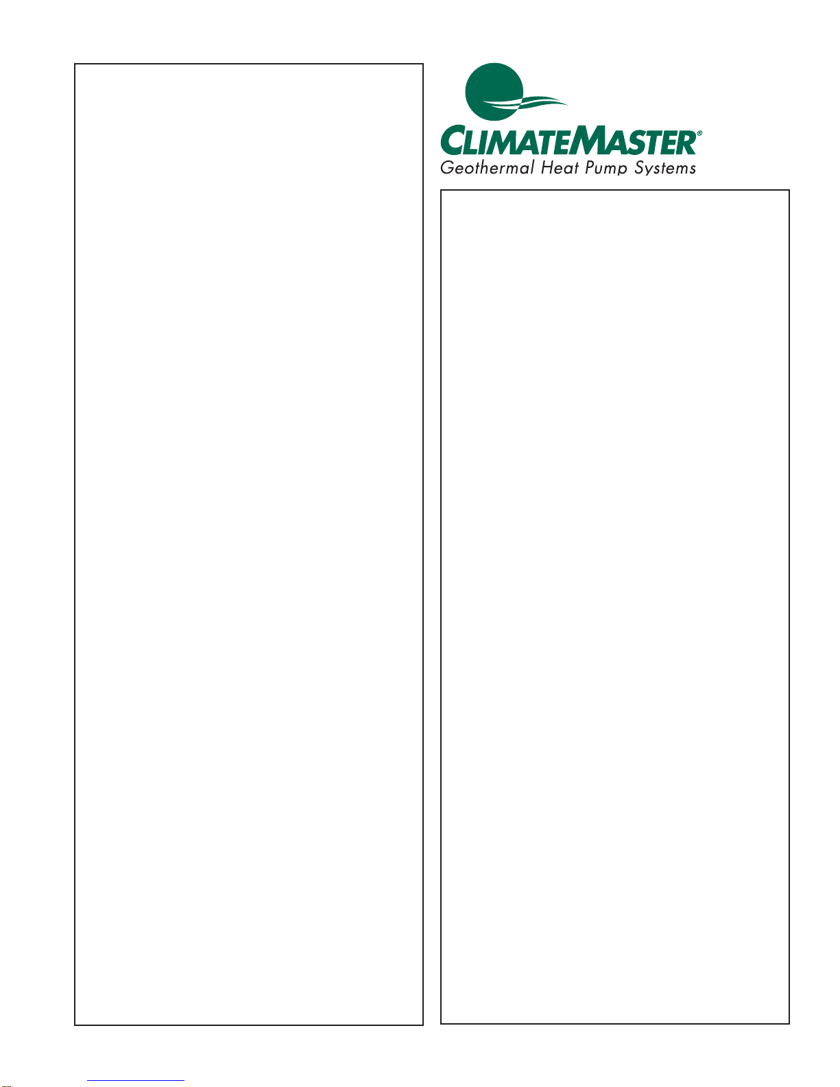
Model Nomenclature: Console (CCE) Series
94 5 6
1 2 3
8 101112131415
7
C C E AB0 7 CG S S C S R S
Standard
S = Standard
Consoles
Rev.: 5 Nov., 2009B
Unit Size
07
09
12
15
19
Revision Level
C = Current
Voltage
A = 115/60/1
E = 265/60/1
G = 208-230/60/1
A = MCO Unit Mounted Tstat w/CXM
B = MCO Unit Mounted Tstat w/DXM
C = ACO Unit Mounted Tstat w/CXM
D = ACO Unit Mounted Tstat w/DXM
R = Remote Mounted Tstat w/CXM
S = Remote Mounted Tstat w/DXM
L = Remote Mounted w/CXM & LON
M = Remote Mounted w/DXM & LON
N = Remote Mounted w/CXM & MPC
P = Remote Mounted w/DXM & MPC
A = Field Connected (Hard Wire)
D = Disconnect Switch & 15Amp Fuse
F = Disconnect Switch (Non Fused)
H = 20Amp Plug, Cord, Receptacle,
Disconnect Switch & 15Amp Fuse
K = 20Amp Plug, Cord, Receptacle &
Disconnect Switch (Non Fused)
Controls
Power Termination
B = 20Amp Plug & Cord
Piping Connections
R = Right Piping
L = Left Piping
Water Circuit Options
None S F M
Motorized Water Valve A G N
Autoflow (2.25 Gpm/Ton) B H P
Autoflow (3.0 Gpm/Ton) C J Q
Motorized Water Valve & Afr (2.25) D K R
Motorized Water Valve & Afr (3.0) E L T
Secondary Circulation Pump U V W
Heat Exchanger Options
A = Copper Water Coil w/E-Coated Air Coil
C = Copper Water Coil
J = Cupro-Nickel Water Coil w/E-Coated Air Coil
N = Cupro-Nickel Water Coil
V = Copper Water Coil w/E-Coated Air Coil & Extended Range Insulation
E = Copper Water Coil w/Extended Range Insulation
M = Cupro-nickel Water Coil w/E-Coated Air Coil & Extended Range Insulation
F = Cupro-nickel Water Coil w/Extended Range Insulation
Subbase
S = 3” Subbase
D = 3” Subbase w/Motorized Damper
G = 5” Subbase
H = 5” Subbase w/Motorized Damper
N = None
Cabinet Construction
With UltraQuiet
M = Bottom Return
D = Bottom Return w/Locking Control Door
B = Front Return
E = Front Return w/Locking Control Door
C = No Cabinet BR Chassis Only
J = No Cabinet FR Chassis Only
Sweat FPT MPT
Without UltraQuiet
S = Bottom Return
L = Bottom Return w/Locking Control Door
F = Front Return
G = Front Return w/Locking Control Door
N = No Cabinet BR Chassis Only
H = No Cabinet FR Chassis Only
Rev.: 8 Aug, 2008B
climatemaster.com
3
CLIMATEMASTER WATER-SOURCE HEAT PUMPS
Consoles
Rev.: 5 Nov., 2009B
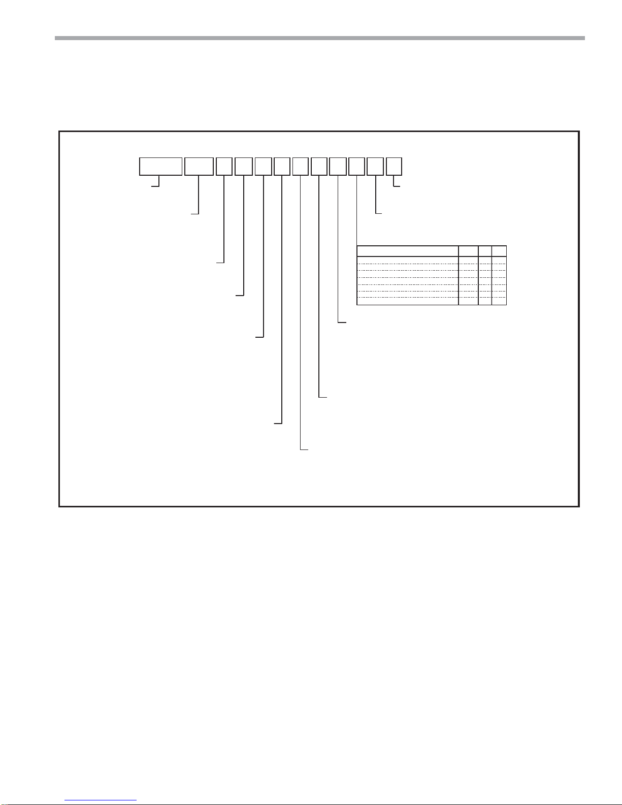
Model Nomenclature: Tranquility Console (TRC) Series (60Hz)
94 5 6
1 2 3
8 101112 131415
7
T R C AA0 9 CG S S C S R S
Model Type
TRC = Console
Unit Size
09, 12, 15, 18
Revision Level
B = Size 09 (115V) & Size 18 (265V)
A = Current Revision
A = MCO Unit Mounted Tstat w/CXM
B = MCO Unit Mounted Tstat w/DXM
C = ACO Unit Mounted Tstat w/CXM
D = ACO Unit Mounted Tstat w/DXM
R = Remote Mounted Tstat w/CXM
S = Remote Mounted Tstat w/DXM
L = Remote Mounted w/CXM & LON
M = Remote Mounted w/DXM & LON
N = Remote Mounted w/CXM & MPC
P = Remote Mounted w/DXM & MPC
D = Disconnect Switch & 15Amp Fuse
K = 20Amp Plug, Cord, Receptacle &
Disconnect Switch (Non Fused)
Voltage
G = 208-230/60/1
A = 115/60/1
E = 265/60/1
Controls
Power Termination
A = Field Connected (Hard Wire)
B = 20Amp Plug & Cord
F = Disconnect Switch (Non Fused)
H = 20Amp Plug, Cord, Receptacle,
Disconnect Switch & 15Amp Fuse
Water Circuit Options
None S F M
Motorized Water Valve A G N
Autoflow (2.25 Gpm/Ton) B H P
Autoflow (3.0 Gpm/Ton) C J Q
Motorized Water Valve & Afr (2.25) D K R
Motorized Water Valve & Afr (3.0) E L T
Secondary Circulation Pump U V W
Heat Exchanger Options
A = Copper Water Coil w/E-Coated Air Coil
C = Copper Water Coil
J = Cupro-Nickel Water Coil w/E-Coated Air Coil
N = Cupro-Nickel Water Coil
V = Copper Water Coil w/E-Coated Air Coil & Extended Range Insulation
E = Copper Water Coil w/Extended Range Insulation
M = Cupro-nickel Water Coil w/E-Coated Air Coil & Extended Range Insulation
F = Cupro-nickel Water Coil w/Extended Range Insulation
Subbase
S = 5” Subbase
H = 5” Subbase w/Motorized Damper
N = None
Cabinet Construction
With UltraQuiet Without UltraQuiet
M = Bottom Return
D = Bottom Return w/Locking Control Door
B = Front Return
E = Front Return w/Locking Control Door
C = No Cabinet BR Chassis Only
J = No Cabinet FR Chassis Only
Standard
S = Standard
Piping Connections
R = Right Piping
L = Left Piping
V = Left Piping w/SS Drain Pan
W = Right Piping w/SS Drain Pan
Sweat FPT MPT
S = Bottom Return
L = Bottom Return w/Locking Control Door
F = Front Return
G = Front Return w/Locking Control Door
N = No Cabinet BR Chassis Only
H = No Cabinet FR Chassis Only
Rev.: 29 July, 2009B
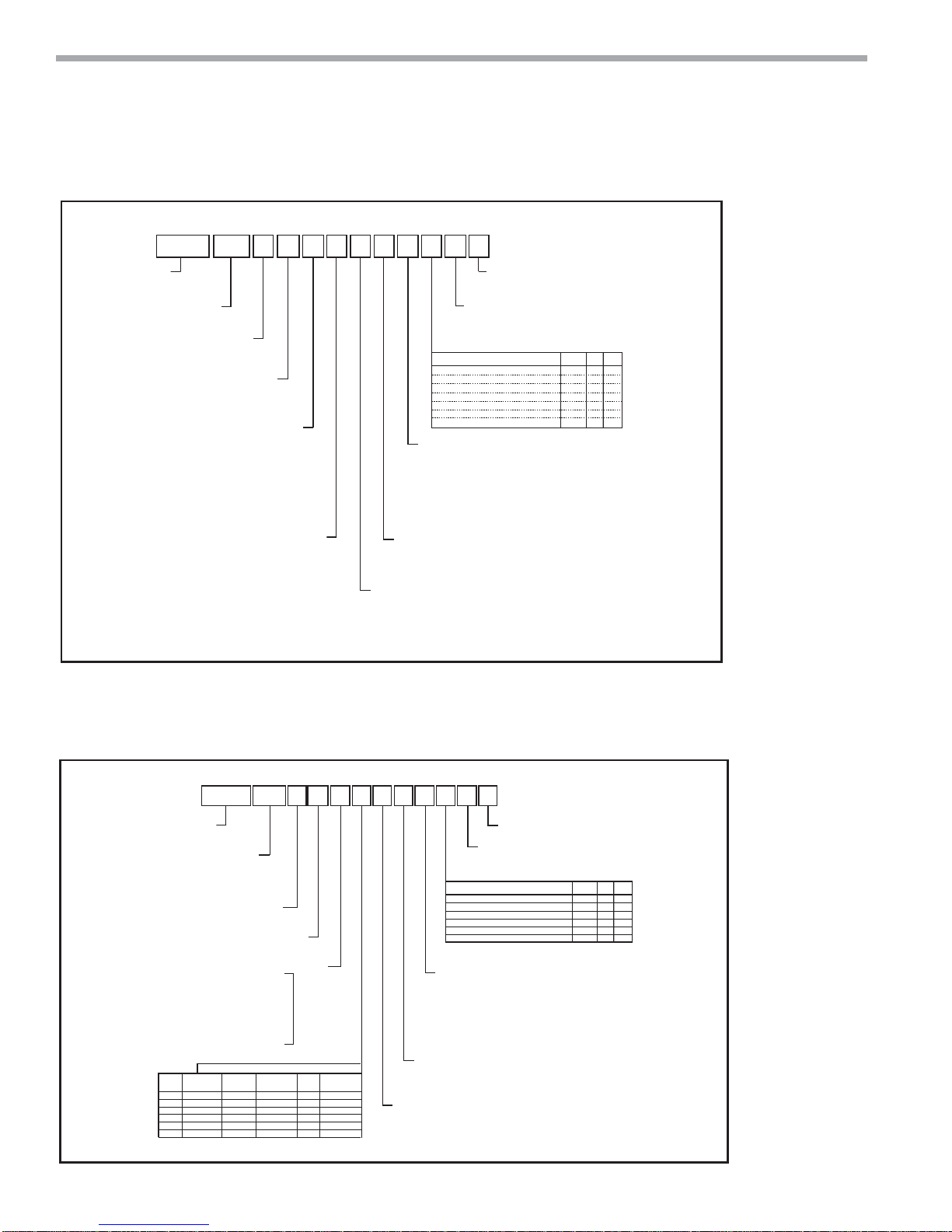
Model Nomenclature: Tranquility Console (TRC) Series (50Hz)
94 5 6
8 101112131415
7
CE Mark
15 Amp
RECEPTACLE
FUSE
-
-
-
-
-
X
-
X
X
X
-
CABINET
S = Bottom Return (Standard)
L = Bottom Return w/Locking Control Door (Standard)
F = Front Return (Standard)
G = Front Return w/Locking Control Door (Standard)
N = No Cabinet Chassis Only (Standard)
S = STANDARD
PIPING CONNECTIONS
R = Right Piping
L = Left Piping
WATER CIRCUIT OPTIONS
None
Motorized Water Valve
AutoFlow (2.25 gpm/ton)
AutoFlow (3.0 gpm/ton)
Motorized Water Valve & AFR (2.25)
Motorized Water Valve & AFR (3.0)
HEAT EXCHANGER OPTIONS
A = Copper Water Coil w/E-Coated Air Coil
C = Copper Water Coil w/Non-Coated Air Coil
J = Cupro-Nickel Water Coil w/E-Coated Air Coil
N = Cupro-Nickel Water Coil w/Non-Coated Air Coil
V = Copper Water Coil w/E-Coated Air Coil & Extended Range Insulation
E = Copper Water Coil w/Non-Coated Air Coil & Extended Range Insulation
M = Cupro-Nickel Water Coil w/E-Coated Air Coil & Extended Range Insulation
F = Cupro-Nickel Water Coil w/Non-Coated Air Coil & Extended Range Insulation
SUBBASE
S = 5” Subbase (Black)
H = 5” Subbase w/Motorized Damper
N = None
Sweat FPT MPT
S F M
A G N
B H P
C J Q
D K R
E L T
SERIES
TRC = Tranquility Console
E = MCO Unit Mounted Tstat w/CXM
F = ACO Unit Mounted Tstat w/CXM
J = MCO Unit Mounted Tstat w/DXM
K = ACO Unit Mounted Tstat w/DXM
Q = Remote Mounted Tstat w/CXM
G = Remote Mounted Tstat w/DXM
H = Remote Mounted LON w/CXM
V = Remote Mounted LON w/DXM
T = Remote Mounted MPC w/CXM
U = Remote Mounted MPC w/DXM
FIELD
OPTION
CONNECTED
(HARD WIRE)
A
B
D
F
H
K
1 2 3
TRC FB12 EV S S E S R S
UNIT SIZE
09
12
15
18
REVISION LEVEL
B = Current Revision
VOLT AGE
V = 220-240/50/1
CONTROLS
POWER TERMINATION & OPTIONS
20 Amp
DISCONNECT
PLUG &
SWITCH
CORD
X
-
-
-
-
-
-
-
-
X
X
X
X
X
X
X
Rev.: 21 Nov, 2007J
4
ClimateMaster Water-Source Heating and Cooling Systems
THE SMART SOLUTION FOR ENERGY EFFICIENCY
Consoles
Rev.: 5 Nov., 2009B
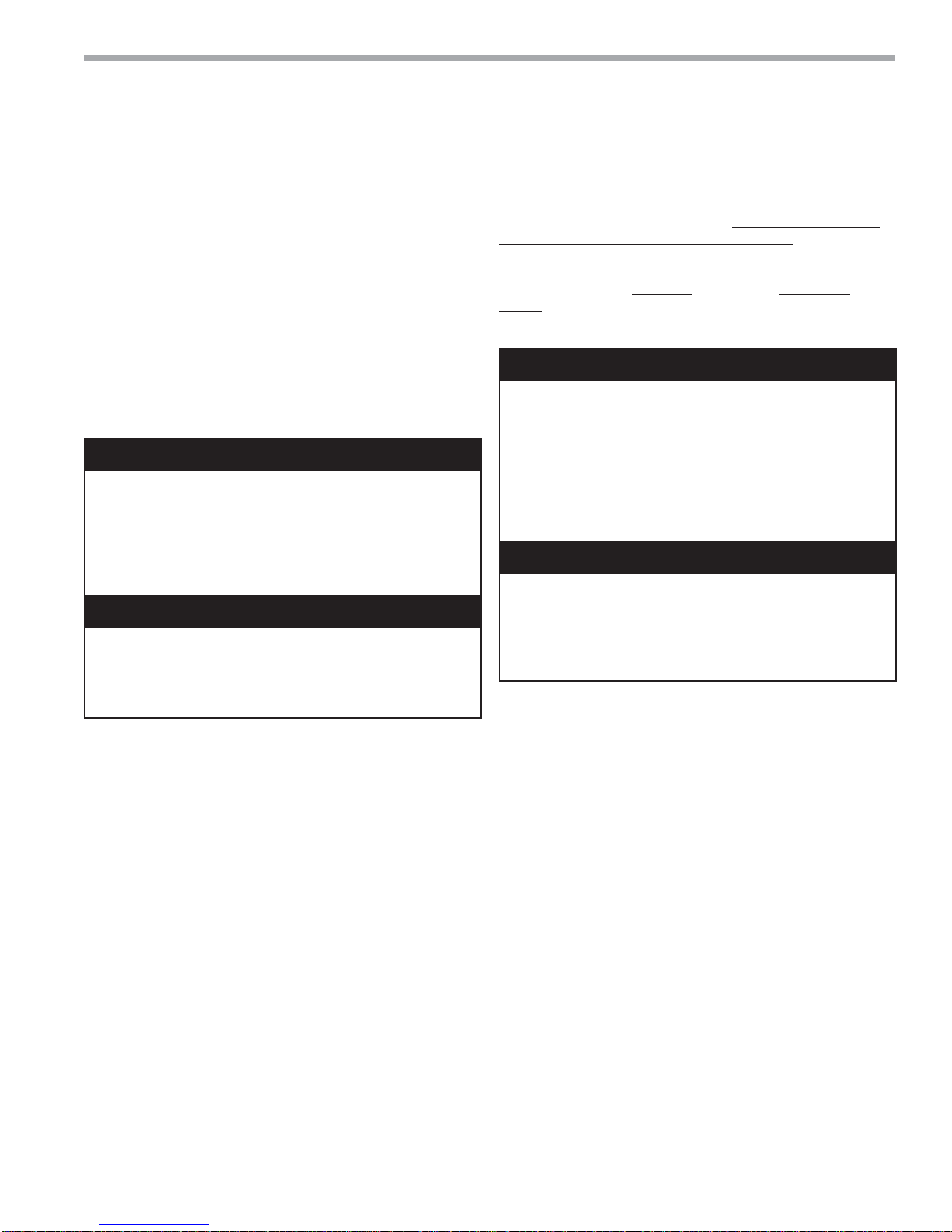
General Information
Safety
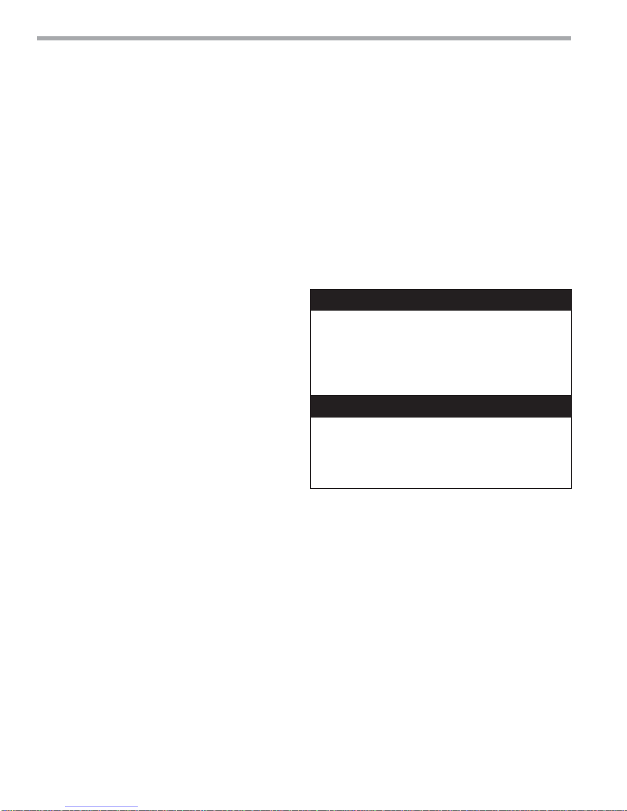
Warnings, cautions and notices appear throughout this manual.
Read these items carefully before attempting any installation,
service or troubleshooting of the equipment.
DANGER: Indicates an immediate hazardous situation, which
if not avoided will result in death or serious injury. DANGER
labels on unit access panels must be observed.
WARNING: Indicates a potentially hazardous situation, which if
not avoided could result in death or serious injury.
WARNING!
WARNING! Verify refrigerant type before proceeding. Units
are shipped with R-22, R-407c and R-410A (EarthPure®)
refrigerants. The unit label will indicate which refrigerant is
provided. The EarthPure® Application and Service Manual
should be read and understood before attempting to service
refrigerant circuits with R-407c or R-410A.
WARNING!
WARNING! To avoid the release of refrigerant into the
atmosphere, the refrigerant circuit of this unit must be
serviced only by technicians who meet local, state, and
federal profi ciency requirements.
CAUTION: Indicates a potentially hazardous situation or an
unsafe practice, which if not avoided could result in minor or
moderate injury or product or property damage.
NOTICE: Notifi cation of installation, operation or maintenance
information, which is important, but which is not hazardrelated.
WARNING!
WARNING! All refrigerant discharged from this unit must be
recovered WITHOUT EXCEPTION. Technicians must follow
industry accepted guidelines and all local, state, and federal
statutes for the recovery and disposal of refrigerants. If a
compressor is removed from this unit, refrigerant circuit oil will
remain in the compressor. To avoid leakage of compressor oil,
refrigerant lines of the compressor must be sealed after it is
removed.
CAUTION!
CAUTION!
these units as a source of heating or cooling during the
construction process. The mechanical components and
fi lters will quickly become clogged with construction dirt
and debris, which may cause system damage.
To avoid equipment damage, DO NOT use
climatemaster.com
5
CLIMATEMASTER WATER-SOURCE HEAT PUMPS
Consoles
Rev.: 5 Nov., 2009B
General Information
Inspection
Upon receipt of the equipment, carefully check the
shipment against the bill of lading. Make sure all units
have been received. Inspect the packaging of each unit,
and inspect each unit for damage. Insure that the carrier
makes proper notation of any shortages or damage on all
copies of the freight bill and completes a common carrier
inspection report. Concealed damage not discovered
during unloading must be reported to the carrier within
15 days of receipt of shipment. If not fi led within 15 days,
the freight company can deny the claim without recourse.
Note: It is the responsibility of the purchaser to fi le all
necessary claims with the carrier. Notify your equipment
supplier of all damage within fi fteen (15) days of shipment.
Storage
Equipment should be stored in its original packaging in
a clean, dry area. Store units in an upright position at all
times. Stack units a maximum of 3 units high.
Unit Protection
Cover units on the job site with either the original
packaging or an equivalent protective covering. Cap
the open ends of pipes stored on the job site. In areas
where painting, plastering, and/or spraying has not been
completed, all due precautions must be taken to avoid
physical damage to the units and contamination by foreign
material. Physical damage and contamination may prevent
proper start-up and may result in costly equipment cleanup.
Examine all pipes, fi ttings, and valves before installing
any of the system components. Remove any dirt or
debris found in or on these components.
3. Verify refrigerant tubing is free of kinks or dents and
that it does not touch other unit components.
4. Inspect all electrical connections. Connections must
be clean and tight at the terminals.
5. Remove any blower support packaging.
6. Loosen compressor bolts on units equipped with
compressor spring vibration isolation until the
compressor rides freely on the springs. Remove
shipping restraints.
7. REMOVE COMPRESSOR SUPPORT PLATE 1/4”
SHIPPING BOLTS (2 on each side) TO MAXIMIZE
VIBRATION AND SOUND ATTENUATION.
CAUTION!
CAUTION! DO NOT store or install units in corrosive
environments or in locations subject to temperature or
humidity extremes (e.g., attics, garages, rooftops, etc.).
Corrosive conditions and high temperature or humidity can
signifi cantly reduce performance, reliability, and service life.
Always move and store units in an upright position. Tilting
units on their sides may cause equipment damage.
CAUTION!
CAUTION! CUT HAZARD - Failure to follow this caution
may result in personal injury. Sheet metal parts may have
sharp edges or burrs. Use care and wear appropriate
protective clothing, safety glasses and gloves when
handling parts and servicing heat pumps.
NOTICE! Failure to remove shipping brackets from springmounted compressors will cause excessive noise, and could
cause component failure due to added vibration.
Pre-Installation
Installation, Operation, and Maintenance instructions
are provided with each unit. Horizontal equipment is
designed for installation above false ceiling or in a ceiling
plenum. Other unit confi gurations are typically installed
in a mechanical room. The installation site chosen
should include adequate service clearance around the
unit. Before unit start-up, read all manuals and become
familiar with the unit and its operation. Thoroughly check
the system before operation.
Prepare units for installation as follows:
1. Compare the electrical data on the unit nameplate
with ordering and shipping information to verify that
the correct unit has been shipped.
2. Keep the cabinet covered with the original packaging
until installation is complete and all plastering,
painting, etc. is fi nished.
6
ClimateMaster Water-Source Heating and Cooling Systems
THE SMART SOLUTION FOR ENERGY EFFICIENCY
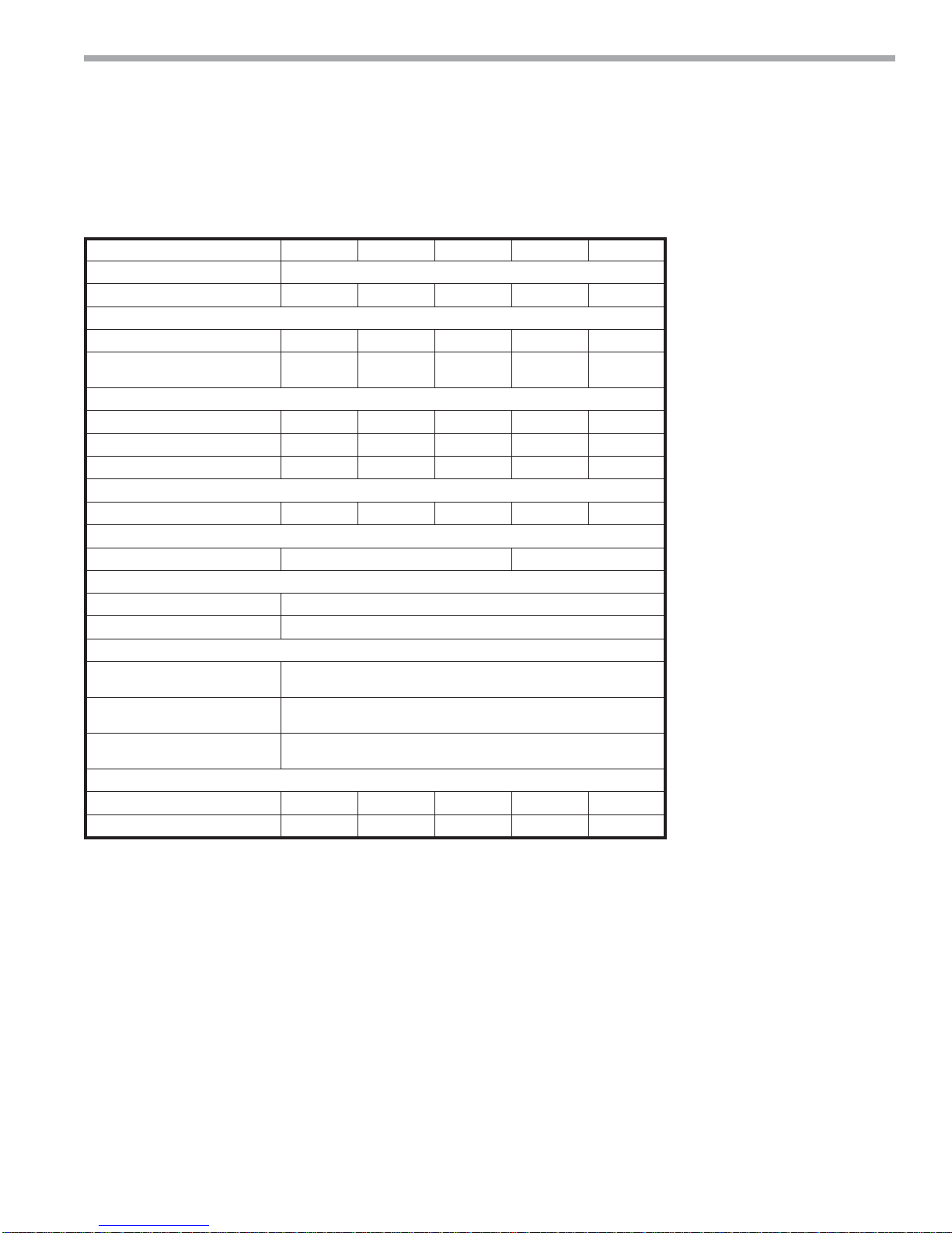
Console (CCE) Series
Model 07 09 12 15 19
Compressor (1 Each) Rotary
Factory Charge R22 (oz) [kg] 16 [0.454] 16 [0.454] 21 [0.595] 27 [0.765] 24 [0.680]
PSC Fan Motor & Blower (3 Speeds)
Fan Motor (hp) [W] 1/20 [27] 1/15 [50] 1/15 [50] 1/6 [124] 1/6 [124]
Blower Wheel Size (dia x w) (in) [mm]
Water Connection Size
O.D. Sweat (in) [mm] 5/8 [15.9] 5/8 [15.9] 5/8 [15.9] 5/8 [15.9] 5/8 [15.9]
Optional IPT Fittings (in) 1/2 1/2 1/2 1/2 1/2
Optional EPT Fittings (in) 1/2 1/2 1/2 1/2 1/2
Condensate Connection Size
I.D. Vinyl Hose (In) [mm] 5/8 [15.9] 5/8 [15.9] 5/8 [15.9] 5/8 [15.9] 5/8 [15.9]
Air Coil Size
Dimensions (h x w) - (in) [mm] 8 x 26 [20.3 x 66.0] 10 x 26 [25.4 x 66.0]
Filter Size
Bottom Return (in) [cm] 1 - 8 x 29-1/2 x 3/8 [20.3 x 74.9 x 0.95]
Front Return (In) [cm] 1 - 7 x 29-1/2 x 1/8 [17.8 x 74.9 x 0.32]
Cabinet Size
Bottom Return (Std. 3" Base)
(W x H x D) - (In) [cm]
Bottom Return (Std. 5" Base)
(W x H x D) - (In) [cm]
Bottom Return (No Subbase)
(W x H x D) - (In) [cm]
Unit Weight
Weight - Operating, (lbs) [kg] 173 [78.5] 177 [80.3] 187 [84.5] 193 [87.5] 198 [89.8]
Weight - Packaged, (lbs) [kg] 181 [82.1] 185 [83.9] 195 [88.5] 201 [91.2] 206 [93.4]
5-1/4 x 6-1/4
[133 x 159]
5-1/4 x 6-1/4
[133 x 159]
48 x 24 x 12 [121.9 x 61.0 x 30.5]
48 x 26 x 12 [121.9 x 66.0 x 30.5]
48 x 21 x 12 [121.9 x 53.3 x 30.5]
5-1/4 x 6-1/4
[133 x 159]
5-1/4 x 6-1/4
[133 x 159]
5-1/4 x 6-1/4
[133 x 159]
Consoles
Rev.: 5 Nov., 2009B
Unit Physical Data
climatemaster.com
7
CLIMATEMASTER WATER-SOURCE HEAT PUMPS
Consoles
Rev.: 5 Nov., 2009B
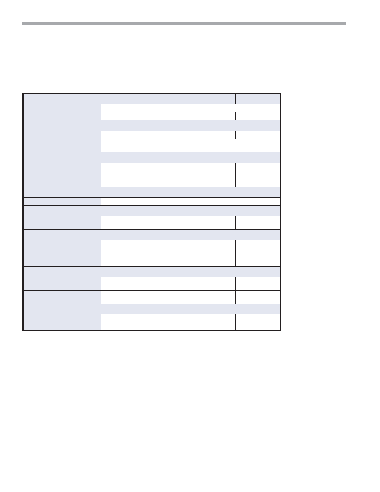
Unit Physical Data
Tranquility Console (TRC) Series (60Hz)
Model 09 12 15 18
Compressor (1 Each)
Factory Charge R410A (oz) [kg] 28 [0.794] 29 [0.822] 33 [0.907] 39 [1.105]
PSC Fan Motor & Blower (3 Speeds)
Fan Motor (hp) [W] 1/20 [37] 1/12 [62] 1/8 [93] 1/8 [93]
Blower Wheel Size (dia x w) -
(in) [mm] - Qty 2
Water Connection Size
O.D. Sweat (in) [mm] 1/2 [12.7] 3/4 [19.1]
Optional IPT Fittings (in) 1/2 3/4
Optional EPT Fittings (in) 1/2 3/4
Condensate Connection Size
I.D. Vinyl Hose (In) [mm] 5/8 [15.9]
Air Coil Size
Dimensions (h x w) - (in) [mm]
8 x 26
[203 x 660]
Filter Size
Bottom Return (in) [mm] 1 - 10 x 30 x 1 [254 x 762 x 25]
Front Return (In) [mm] 1 - 7 x 29.5 x 1/8 [178 x 749 x 3.2]
Cabinet Size
Bottom Return (Std. 5" Base)
(W x H x D) - (In) [mm]
Front Return (No Subbase)
(W x H x D) - (In) [mm]
48 x 26 x 12 [1219 x 660 x 305]
48 x 21 x 12 [1219 x 533 x 305]
Cabinet Size
Weight - Operating, (lbs) [kg] 175 [79] 180 [82] 190 [86.2] 220 [99.8]
Weight - Packaged, (lbs) [kg] 185 [83.9] 190 [86] 200 [90.8] 232 [105.2]
5.25 x 6.25 [133 x 159]
10 x 26 [254 x 660]
10 x 32
[254 x 812]
1 - 10 x 36 x 1
[254 x 914 x 25]
1 - 7 x 35.5 x 1/8
[178 x 902 x 3.2]
54 x 26 x 12
[1372 x 660 x 305]
54 x 21 x 12
[1372 x 533 x 305]
* Data not available at time of publication.
All units have rubber grommet compressor mountings and TXV expansion devices.
8
ClimateMaster Water-Source Heating and Cooling Systems
THE SMART SOLUTION FOR ENERGY EFFICIENCY
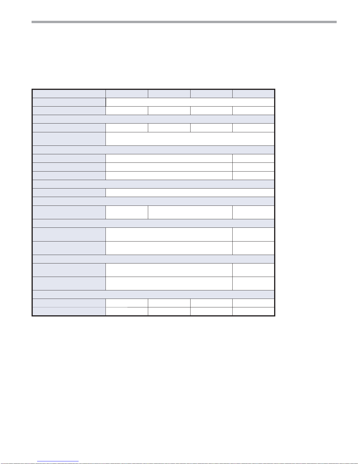
Tranquility Console (TRC) Series (50Hz)
Model 09 12 15 18
Compressor (1 Each) Rotary
Factory Charge R410A (oz) [kg] 26 [0.737] 29 [0.822] 33 [0.936] 30 [0.850]
PSC Fan Motor & Blower (3 Speeds)
Fan Motor (hp) [W] 1/20 [37] 1/12 [62] 1/8 [93] 1/8 [93]
Blower Wheel Size (dia x w) (in) [mm] - Qty 2
Water Connection Size
O.D. Sweat (in) [mm] 1/2 [12.7] 3/4 [19.1]
Optional IPT Fittings (in) 1/2 3/4
Optional EPT Fittings (in) 1/2 3/4
Condensate Connection Size
I.D. Vinyl Hose (In) [mm] 5/8 [15.9]
Air Coil Size
Dimensions (h x w) - (in) [mm]
8 x 26
[203 x 660]
Filter Size
Bottom Return (in) [mm] 1 - 10 x 30 x 1 [254 x 762 x 25]
Front Return (In) [mm] 1 - 7 x 29.5 x 1/8 [178 x 749 x 3.2]
Cabinet Size
Bottom Return (Std. 5" [127] Base)
(W x H x D) - (In) [mm]
Front Return (No Subbase)
(W x H x D) - (In) [mm]
48 x 26 x 12 [1219 x 660 x 305]
48 x 21 x 12 [1219 x 533 x 305]
Cabinet Size
Weight - Operating, (lbs) [kg] 175 [79] 180 [82] 190 [86.2] 220 [99.8]
Weight - Packaged, (lbs) [kg] 185 [83.9] 190 [86] 200 [90.8] 232 [105.2]
5.25 x 6.25 [133 x 159]
10 x 26 [254 x 660]
10 x 32
[254 x 813]
1 - 10 x 36 x 1
[25.4 x 91.4 x 2.5]
1 -7 x 35.5 x 1/8
[178 x 902 x 3.2]
54 x 26 x 12
[1372 x 660 x 305]
54 x 21 x 12
[1372 x 533 x 305]
Consoles
Rev.: 5 Nov., 2009B
Unit Physical Data
All units have rubber grommet compressor mountings and TXV expansion devices.
climatemaster.com
9

CLIMATEMASTER WATER-SOURCE HEAT PUMPS
Consoles
Rev.: 5 Nov., 2009B
Installation
The installation of Console Water-Source Heat Pumps
and all associated components, parts and accessories
that make up the installation shall be in accordance with
the regulations of ALL Authorities having jurisdiction
and MUST conform to all applicable Codes. It is the
responsibility of the Installing Contractor to determine
and comply with ALL applicable Codes and Regulations.
NOTE: An Installation Checklist is provided in this
manual. Complete this checklist after all installation
procedures are completed. A periodic maintenance
checklist provided in the Maintenance section outlines
recommended maintenance schedules. A Start-Up
Inspection Log is also included at the end of this manual
to encourage thorough unit checkout at initial start-up.
These checklists are not a substitute for the detailed
information found in the Installation section of this
manual
1. Console units are typically installed along an outside
2. Unpack the Console Unit from the shipping carton.
3. Remove compressor isolation plate shipping screws
4. Using a carpenter's square and a level, ensure the
.
wall of the room. Provide adequate space in front
of the unit for service and maintenance. Locate
the Console Unit so that it provides adequate air
circulation throughout the room.
Remove the front cabinet by lifting up and away from
the backplate. Protect the cabinet from damage
during installation by returning it to its original
packaging until required.
(4) as shown in Figure 1a. (All CCE and TRC09-12)
unit is level. Shim the unit if necessary to assure
proper installation.
CAUTION!
Poor or inadequate installation may result in noisy unit
operation or unattractive installation.
Figure 1a: Compressor Shipping Screws (All
CCE and TRC 09-12)
4 Shipping
Screws
5. Select the proper fasteners to connect the backplate
securely to the wall.
6. Fasten the backplate onto the wall through the screw
holes located in the back fl ange. Secure the subbase
in place.
7. Make all necessary electrical connections as
described in the Electrical Wiring section of this
manual. Consult the wiring diagram to ensure proper
hook-up.
8. Connect the fi nal piping as described in the Supply
and Return Piping and Condensate Piping section
of the manual. Install shut-off valves, piping and/or
hoses and other accessories as specifi ed.
9. Before making the fi nal water connections, fl ush
the system as described in the Start Up section
of this manual. After fl ushing the system, connect
piping and hoses to the proper supply, return and
condensate connections of the unit.
NOTE: When necessary, use adapters to connect hoses.
10. Install any other system components as required
following manufacturer's instructions.
11. After Start-up, reinstall the front cabinet by
carefully lowering the front cabinet over the chassis
onto the backplate.
Supply and Return Hoses
Optional pressure-rated hose assemblies are available
for use with ClimateMaster Console Units. Use the
following guidelines when installing supply and return
hose assemblies.
1. Install supply and return hoses fi tted with swivel-joint
fi ttings at one end to prevent the hose from twisting.
2. Use adapters to secure the hose assembly to the unit
and the riser.
3. Do not allow the hose to twist during installation.
Twisting may damage the hose wall or the interior
rubber compound.
4. Use pipe joint compound sparingly on the pipe
threads of the fi tting adapters.
5. Prevent sealant from reaching the fl ared surfaces of
the joint.
6. Do not use pipe joint compound when tefl on thread
tape is pre-applied to hose assemblies or when
fl ared-end connections are used.
7. Maximum torque which may be applied to brass
fi ttings is 30 ft-lbs [41 N-m]. When a torque wrench
is not used, tighten brass fi ttings fi nger-tight plus one
quarter turn.
8. Tighten steel fi ttings as necessary.
9. Shut-off/balancing valves, fl ow indicators, and drain
tees in the supply runout and return at each fl oor to
aid in loop balancing and servicing.
10
ClimateMaster Water-Source Heating and Cooling Systems

THE SMART SOLUTION FOR ENERGY EFFICIENCY
Consoles
Rev.: 5 Nov., 2009B
Installation
CAUTION!
Loop Fluids should be of good quality with no more than 0.50
ppm of chlorides w/copper heat exchangers (125 ppm w/
Cupro-nickel) to prevent corrosion and should also be fi ltered
to a maximum 800 micron [0.8mm particle size to prevent
erosion of the heat exchangers.
Condensate Piping
Unit is supplied with condensate drain hose, 5/8
inch [16mm] I.D. fl exible plastic nonpressure-rated,
protruding from piping side of unit. Connect this hose
to building drain. Avoid making kinks in hose to ensure
an unobstructed fl ow of condensate from the unit to the
drain. DO NOT twist, pull hose out, or push excess
hose into unit. If hose will not connect to your building
drain several options include, relocate end of building
drain, add to or cut hose, use hard plastic or copper
elbow fi ttings for tight radii (put inside hose). Keep hose
positioned within or over subbase area so hose does not
interfere with front cabinet. Cabinet should not push or
reroute hose. Clamp all joints watertight. Check for leaks.
Internally the drain hose is clamped to drain pan and
pitched correctly. Horizontal runs of condensate hose
should be pitched downward 1/4 inch minimum for every
foot [10mm per 46cm] of hose. Avoid low points because
dirt collects in these areas and may cause blockage. If
blocked the condensate level in drain pan increases.
When the level gets too high, the Console unit has sensor
switch that will shut unit off. Overfl ow may still occur.
If the building drain connection is parallel with fl oor,
the height can be up to 1-1/2 inches [38mm] above
the subbase for proper pitch and correct drainage. Up
to 5 inches [127mm] above the subbase is allowable,
but drainage will be slower. When the drain connection
is 2-1/2 to 5 inches [64 to 127mm] above, the hose
inside the unit will act as a trap. Heights of more than 5
inches [127mm] above the subbase are NOT allowable
(condensate overfl ow may occur). If the unit has a
disconnect option, drain locations are limited. See unit
confi guration pages for details.
Field installation of a trap or vent is not required unless
specifi ed by local codes. Console units are designed
in a blow-through confi guration. The condensate drain
pan is located on the outlet side of the blower so that
the pressure in the drain pan is higher than atmospheric
pressures.
When drain connection is completed check for proper
drainage and leaks. Correct if necessary.
If trap is used, check and clean often. See Preventive
Maintenance Instructions.
climatemaster.com
11
CLIMATEMASTER WATER-SOURCE HEAT PUMPS
Consoles
Rev.: 5 Nov., 2009B
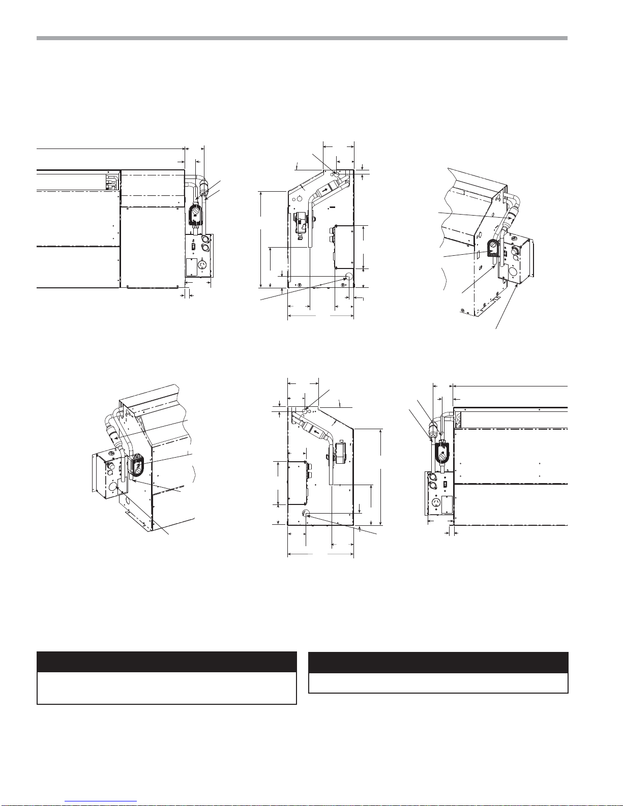
Piping Connections - CCE
Figure 1b: Water Connection Details
3.28
(83)
1.84
(47)
4.46
(113)
0.75
(19)
Water Out
Water In
Condensate
5/8" (15.9 mm)
ID Vinyl Hose
Control Box
Compressor
Access
Panel
Right Hand Configuration
Optional
Autoflow
Valve
Power Supply
30°
*16.66
(423)
*1.94
(49)
*7.06
(179)
3.88
(99)
5.36
(136)
3.01
(76)
0.87
(22)
5.36
(136)
3.01
(76)
3.43
(87)
11. 54
(293)
Power Supply
30°
0.87
(22)
7.5
(191)
3.56
(90)
0.99
(25)
Optional
Motorized
Water Valve
Water Connections
5/8" (15.9 mm)
OD Copper,
1/2" IPT or
1/2" EPT
Water Out
Water In
Optional
Autoflow
Valve
3.50
(89)
1.93
Optional
Disconnect Box
(mounted to cabinet
not chassis)
(49)
Optional
Motorized
Water Valve
7.5
Water Connections
5/8" (15.9 mm)
OD Copper,
1/2" IPT or
1/2" EPT
Optional
Disconnect Box
(mounted to cabinet
not chassis)
(191)
3.56
(90)
Left Hand Configuration
Notes:
All Dimensions are in inches (mm)
* For installed dimension, add to dimension shown 2.9" [74mm] with 3" subbase and 4.9" [124mm] for 5" subbase.
Optional autoflow valve, motorized water valve and disconnect box are shown.
Water connection in same location regardless of connection type.
CAUTION!
CAUTION! Corrosive system water requires corrosion re-
sistant fi ttings and hoses, and may require water treatment.
3.42
(87)
3.22
(82)
11. 54
(293)
3.88
(99)
*1.94
(49)
*7.06
(179)
*16.66
(423)
Condensate
5/8" (15.9 mm)
ID Vinyl Hose
4.49
(114)
Blower Deck
Blower Access Panel
0.75
(19)
CAUTION!
CAUTION! Piping must comply with all applicable codes.
12
ClimateMaster Water-Source Heating and Cooling Systems
Control Box
o
r
r
i
o
v
C
5
p
T
P
y
a
1.62 (41)
2.00
(51)
THE SMART SOLUTION FOR ENERGY EFFICIENCY
Consoles
Rev.: 5 Nov., 2009B
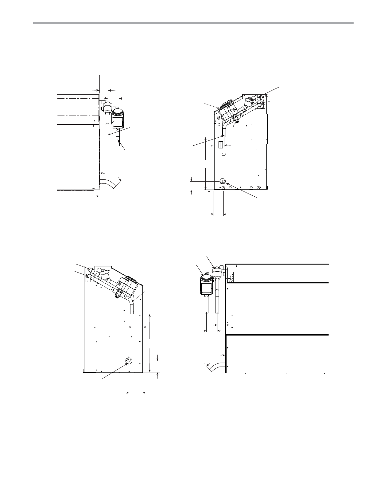
Piping Connections -
TRC Size 06-15
Optional Flow
Optional
Motorized
Water Valve
Regulator
Out
In
al
w
e
Compressor
Access
Panel
Out
In
Water Out
Water In
Water Connections
5/8” (15.9) OD
Copper, 1/2” IPT, or
1/2” EPT
2.25
(57)
*11.25 (286)
8.00 Min
(203)
1.75 (44)
Condensate
1.84
(77)
5/8" (15.9) ID
Vinyl Hose
Right Hand Configuration
Water Out
Water In
Water Connections
5/8” (15.9) OD
Copper, 1/2” IPT,
or 1/2” EPT
Opt
Aut
Val
Opti
Moto
Wate
Water
5/8" (1
OD Co
1/2" IP
1/2" E
nal
ized
lve
2.25
(57)
nnections
AA)
r,
r
Condensate
5/8" (15.9) ID
Vinyl Hose
Left Hand Configuration
Notes:
* Dimension reduced b
2.72
(96)
*11.25 (286)
2.25
(57)
fitting if selected
climatemaster.com
2.00
(51)
8.00 Min
(203)
1.50 (38)
Rev.: 10/06/08B
13
CLIMATEMASTER WATER-SOURCE HEAT PUMPS
n
T
O
R
Consoles
Rev.: 5 Nov., 2009B
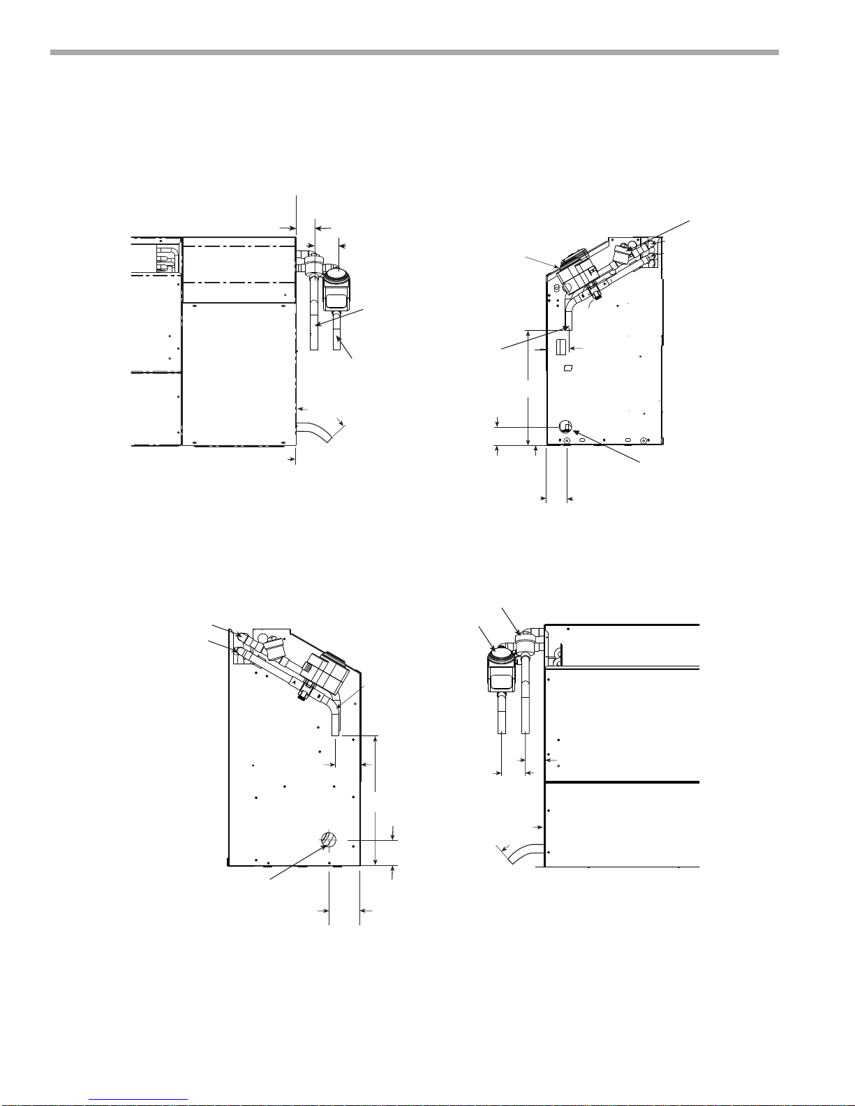
Piping Connections TRC Size 18
nal
low
lve
Control Box
Out
In
Compressor
Access
Panel
1.62 (41)
2.00
(51)
Optional
Motorized
Water Valve
Out
In
Water Out
2.25
(57)
Water In
Water Connections
5/8” (15.9) OD
Copper, 1/2” IPT, or
1/2” EPT
*11.25 (286)
8.00 Min
(203)
1.75 (44)
Condensate
1.84
(77)
5/8" (15.9) ID
Vinyl Hose
Right Hand Configuratio
Water Out
Water In
Water Connections
5/8” (15.9) OD
Copper, 1/2” IPT,
or 1/2” EPT
tional
rized
Valve
onnections
.9AA)
per,
or
Condensate
5/8" (15.9) ID
Vinyl Hose
14
ClimateMaster Water-Source Heating and Cooling Systems
2.25
(57)
2.00
(51)
1.50 (38)
*11.25 (286)
8.00 Min
(203)
2.72
(96)
2.25
(57)
Left Hand Configuration
THE SMART SOLUTION FOR ENERGY EFFICIENCY
Consoles
Rev.: 5 Nov., 2009B
Piping Connections
Installation of Supply and Return Piping
Follow these piping guidelines.
1. Install a drain valve at the base of each supply and
return riser to facilitate system fl ushing.
2. Install shut-off / balancing valves and unions at each
unit to permit unit removal for servicing.
3. Place strainers at the inlet of each system
circulating pump.
4. Select the proper hose length to allow slack between
connection points. Hoses may vary in length by +2%
to -4% under pressure.
5. Refer to Table 1. Do not exceed the minimum bend
radius for the hose selected. Exceeding the minimum
bend radius may cause the hose to collapse, which
reduces water fl ow rate. Install an angle adapter to
avoid sharp bends in the hose when the radius falls
below the required minimum.
Insulation is not required on loop water piping except
where the piping runs through unheated areas, outside
the building or when the loop water temperature is
below the minimum expected dew point of the pipe
ambient conditions. Insulation is required if loop water
temperature drops below the dew point (insulation is
required for ground loop applications in most climates).
Pipe joint compound is not necessary when Tefl on®
thread tape is pre-applied to hose assemblies or when
fl ared-end connections are used. If pipe joint compound
is preferred, use compound only in small amounts on
the external pipe threads of the fi tting adapters. Prevent
sealant from reaching the fl ared surfaces of the joint.
Note: When anti-freeze is used in the loop, insure
that it is compatible with the Tefl on tape or pipe joint
compound that is applied.
Maximum allowable torque for brass fi ttings is 30 ft-lbs
[41 N-m]. If a torque wrench is not available, tighten
fi nger-tight plus one quarter turn. Tighten steel fi ttings
as necessary.
Optional pressure-rated hose assemblies designed
specifi cally for use with ClimateMaster units are available.
Similar hoses can be obtained from alternate suppliers.
Supply and return hoses are fi tted with swivel-joint
fi ttings at one end to prevent kinking during installation.
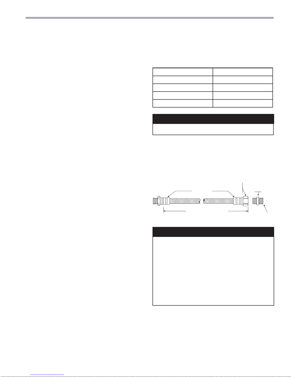
Table 1: Metal Hose Minimum Bend Radii
Hose Diameter Minimum Bend Radii
1/2" [12.7mm] 2-1/2" [6.4cm]
3/4" [19.1mm] 4" [10.2cm]
1" [25.4mm] 5-1/2" [14cm]
1-1/4" [31.8mm] 6-3/4" [17.1cm]
CAUTION!
CAUTION! Do not bend or kink supply lines or hoses.
NOTICE! Do not allow hoses to rest against structural
building components. Compressor vibration may be
transmitted through the hoses to the structure, causing
unnecessary noise complaints.
Figure 2: Supply/Return Hose Kit
Rib Crimped
Length
(2 ft [0.6m] Length Standard)
Swivel
Brass
Fitting
Brass
Fitting
CAUTION!
CAUTION! Many units are installed with a factory or fi eld
supplied manual or electric shut-off valve. DAMAGE WILL
OCCUR if shut-off valve is closed during unit operation. A
high pressure switch must be installed on the heat pump side
of any fi eld provided shut-off valves and connected to the
heat pump controls in series with the built-in refrigerant circuit
high pressure switch to disable compressor operation if water
pressure exceeds pressure switch setting. The fi eld installed
high pressure switch shall have a cut-out pressure of 300
psig and a cut-in pressure of 250 psig. This pressure switch
can be ordered from ClimateMaster with a 1/4” internal fl are
connection as part number 39B0005N02.
EPT
Refer to Figure 2 for an illustration of a typical supply/
return hose kit. Adapters secure hose assemblies to
the unit and risers. Install hose assemblies properly and
check regularly to avoid system failure and reduced
service life.
climatemaster.com
15
 Loading...