

ClimateMaster Tranquility TZH 024 Series, Tranquility TZH 060 Series, Tranquility TZV 024 Series, Tranquility TZV 060 Series Installation, Operation & Maintenence Manual
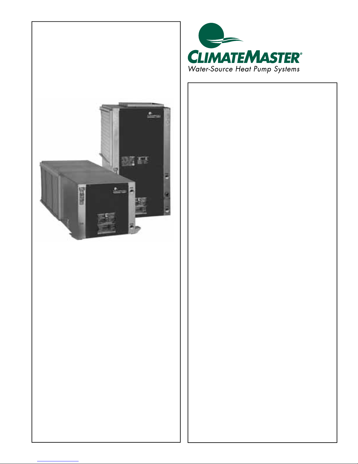
Tranquility® 22
(TZ) Series
Models TZH/V 024 - 060
60 Hz - HFC-410A
INSTALLATION, OPERATION,
& MAINTENANCE
97B0075N16
Revised: 21 January, 2013
Table of Contents
Model Nomenclature 3
General Information 5
Unit Physical Data 6
Horizontal Installation 7
Field Conversion of Air Discharge 9
Horizontal Installation 10
Vertical Installation 11
Piping Installation 13
vFlow™ Heat Pump Applications Overview 14
Water-Loop Heat Pump Applications 17
Ground-Loop Heat Pump Applications 18
Ground-Loop and Ground Water Heat
Pump Applications 19
Ground-Water Heat Pump Applications 20
Water Quality Standards 22
Electrical - Line Voltage 23
Electrical Data 25
Electrical - Power & Low Voltage Wiring 26
Electrical - Low Voltage Wiring 27
Electrical - Low Voltage Wiring for non-vFlow
Using External Motorized Water Valve 28
Electrical - Thermostat Wiring 29
Blower Performance Data 30
ECM Blower Control 31
Typical Wiring Diagram - Single Phase Units 32
Typical Wiring Diagram - Single Phase Unit
with MPC Controller 33
Typical Wiring Diagram - Three Phase Units 34
DXM2 Controls 35
DXM2 Layout and Connections 38
Unit Starting and Operating Conditions 41
Piping System Cleaning and Flushing 42
Unit and System Checkout 43
Unit Start-Up Procedure 44
Unit Operating Conditions 46
Preventive Maintenance 48
Troubleshooting 49
DXM2 Process Flow Chart 51
Functional Troubleshooting 52
Performance Troubleshooting 54
Start-Up Log Sheet 56
Functional Troubleshooting 57
Warranty (U.S. & Canada) 58
Warranty (International) 59
Revision History 60
™
Units

CLIMATEMASTER WATER-SOURCE HEAT PUMPS
Tranquility
Revised: 01/21/13
®
22 (TZ) Series
This Page Intentionally Left Blank
2
ClimateMaster Water-Source Heat Pumps
THE SMART SOLUTION FOR ENERGY EFFICIENCY
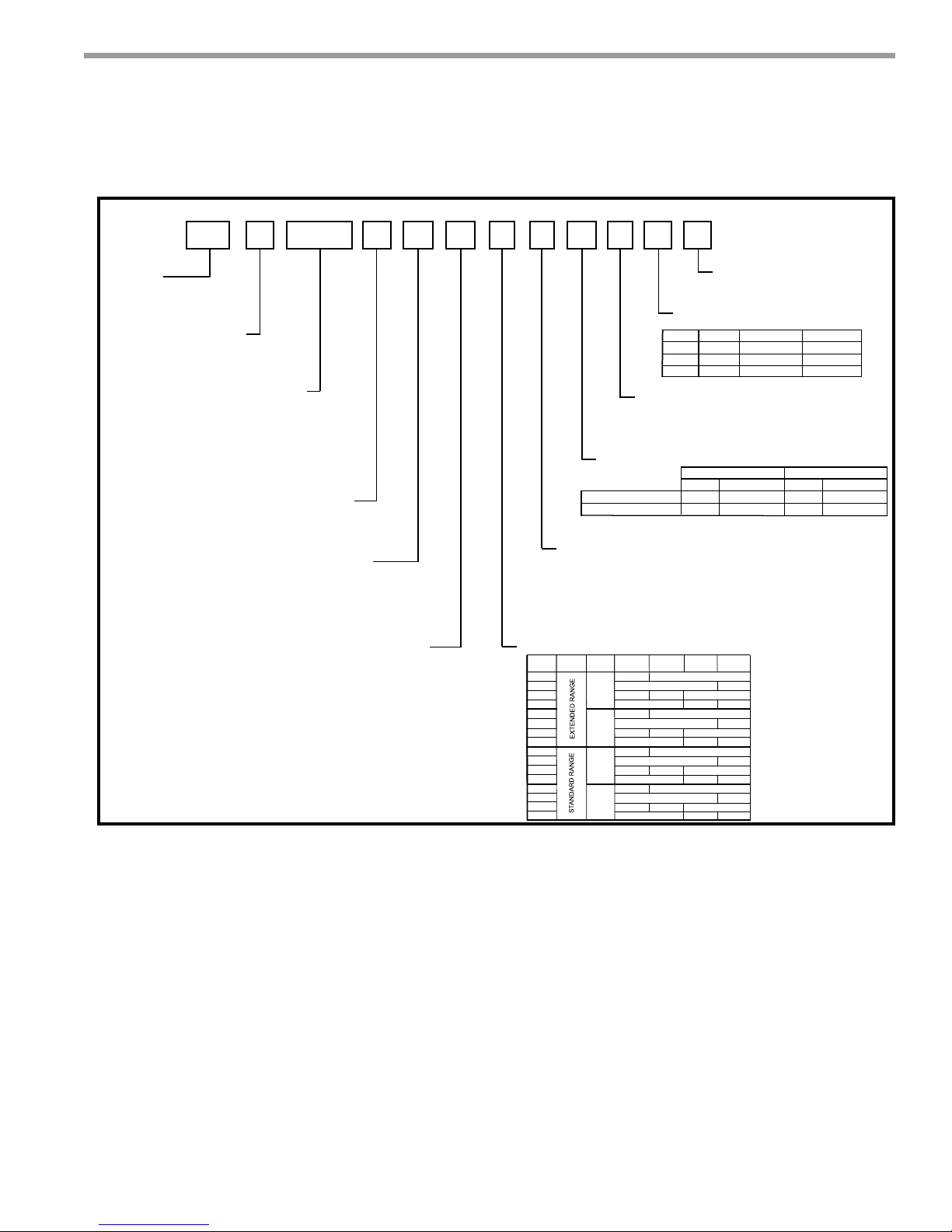
1 2
TZ
SERIES
TZ = Tranquility® 22 Digital
CONFIGURATION
V = Vertical Up
H = Horizontal
4 5 6 7
3
V
UNIT SIZE
024
030
036
042
048
060
REVISION LEVEL
A = Current Revision
Tranquility
91011121314
8
A0 2 4 DG 1 2 C L T
RETURN AIR FLOW CONFIGURATION
L = Left Return
R = Right Return
V = Left Return, Stainless Steel Drain Pan
W = Right Return, Stainless Steel Drain Pan
HEAT EXCHANGER OPTIONS
Standard
HWG (Coil Only)
®
22 (TZ) Series
Revised: 01/21/13
Model Nomenclature
15
S
STANDARD
S = Standard
SUPPLY AIR FLOW &
MOTOR CONFIGURATION
TTZV
BTZH
STZH
Copper
Supply
Straight
B
T
Top
Back
Configuration
Cupro-Nickel
G
S
Tin Plated Air CoilNon Coated Air Coil
Copper
A
U
Motor
ECM
ECM
ECM
Cupro-Nickel
J
W
WATER CIRCUIT OPTIONS
VOLTAGE
G = 208-230/60/1
E = 265/60/1
F = 460/60/3
H = 208-230/60/3
CONTROLS
D = DXM2
M = DXM2 w/LON
P = DXM2 w/MPC
3 = Internal Pump Standard Head (Variable) UPM-Geo
4 = Internal Pump High Head (Variable) Magna Pump
5 = Motorized Valve (Modulating) Closed Loop Applications,
Low System Pressure Drop
6 = Motorized Valve (Modulating) Open Loop Applications,
High System Pressure Drop
7 = Internal Secondary Pump
CABINET
OPTION
RANGE
1
A
J
K
2
C
L
M
3
E
N
P
4
G
R
S
ULTRA
QUIET
NO
YES
NO
YES
1” FILTER
RACK
YES
NO
YES
NO
YES
NO
YES
NO
2” FILTER
NO
NO
NO
NO
RACK
YES
YES
YES
YES
1” FILTER
2” FILTER
FRAME
NO
NO
NO
YES
NO
NO
NO
YES
NO
NO
NO
YES
NO
NO
NO
YES
FRAME
YES
NO
YES
NO
YES
NO
YES
NO
Note: Above model nomenclature is a general reference. Consult individual engineering guides for
detailed information.
climatemaster.com
3
CLIMATEMASTER WATER-SOURCE HEAT PUMPS
S
P
on
Tranquility
Revised: 01/21/13
®
22 (TZ) Series
General Information
Safety
Warnings, cautions, and notices appear throughout this
manual. Read these items carefully before attempting any
installation, service, or troubleshooting of the equipment.
DANGER: Indicates an immediate hazardous situation,
which if not avoided will result in death or serious injury.
DANGER labels on unit access panels must be observed.
WARNING: Indicates a potentially hazardous situation,
which if not avoided could result in death or serious injury.
CAUTION: Indicates a potentially hazardous situation or
an unsafe practice, which if not avoided could result in
minor or moderate injury or product or property damage.
NOTICE: Notifi cation of installation, operation, or
maintenance information, which is important, but which is
not hazard-related.
WARNING!
WARNING! To avoid the release of refrigerant into the
atmosphere, the refrigerant circuit of this unit must be
serviced only by technicians who meet local, state, and
federal profi ciency requirements.
CAUTION!
CAUTION! To avoid equipment damage, DO NOT use
these units as a source of heating or cooling during the
construction process. The mechanical components and fi lters
will quickly become clogged with construction dirt and debris,
which may cause system damage.
WARNING!
WARNING! The installation of water-source heat pumps and
all associated components, parts, and accessories which
make up the installation shall be in accordance with the
regulations of ALL authorities having jurisdiction and MUST
conform to all applicable codes. It is the responsibility of
the installing contractor to determine and comply with ALL
applicable codes and regulations.
torage
re-Installati
WARNING!
WARNING! All refrigerant discharged from this unit must
be recovered WITHOUT EXCEPTION. Technicians must
follow industry accepted guidelines and all local, state, and
federal statutes for the recovery and disposal of refrigerants.
If a compressor is removed from this unit, refrigerant circuit
oil will remain in the compressor. To avoid leakage of
compressor oil, refrigerant lines of the compressor must be
sealed after it is removed.
Inspection - Upon receipt of the equipment, carefully
check the shipment against the bill of lading. Make sure
all units have been received. Inspect the packaging of
each unit, and inspect each unit for damage. Ensure that
the carrier makes proper notation of any shortages or
damage on all copies of the freight bill and completes a
common carrier inspection report. Concealed damage
not discovered during unloading must be reported to the
carrier within 15 days of receipt of shipment. If not fi led
within 15 days, the freight company can deny the claim
without recourse.
Note: It is the responsibility of the purchaser to fi le all
necessary claims with the carrier. Notify your equipment
supplier of all damage within fi fteen (15) days of
shipment.
Storage - Equipment should be stored in its original
packaging in a clean, dry area. Store units in an upright
position at all times. Stack units a maximum of 3 units
high.
Unit Protection - Cover units on the job site with either
the original packaging or an equivalent protective
covering. Cap the open ends of pipes stored on the
job site. In areas where painting, plastering, and/or
spraying has not been completed, all due precautions
must be taken to avoid physical damage to the units
and contamination by foreign material. Physical damage
and contamination may prevent proper start-up and may
result in costly equipment clean-up.
4
ClimateMaster Water-Source Heat Pumps

THE SMART SOLUTION FOR ENERGY EFFICIENCY
Examine all pipes, fi ttings, and valves before installing
any of the system components. Remove any dirt or debris
found in or on these components.
Pre-Installation - Installation, Operation, and
Maintenance instructions are provided with each unit.
Horizontal equipment is designed for installation
above false ceiling or in a ceiling plenum. Other unit
confi gurations are typically installed in a mechanical
room. The installation site chosen should include
adequate service clearance around the unit. Before unit
start-up, read all manuals and become familiar with the
unit and its operation. Thoroughly check the system
before operation.
Prepare units for installation as follows:
1. Compare the electrical data on the unit nameplate
with ordering and shipping information to verify that
the correct unit has been shipped.
2. Keep the cabinet covered with the original packaging
until installation is complete and all plastering,
painting, etc. is fi nished.
3. Verify refrigerant tubing is free of kinks or dents and
that it does not touch other unit components.
4. Inspect all electrical connections. Connections must
be clean and tight at the terminals.
5. Remove any blower support packaging (water-to-air
units only).
6. Loosen compressor bolts on units equipped with
compressor spring vibration isolation until the
compressor rides freely on the springs. Remove
shipping restraints. (No action is required for
compressors with rubber grommets.)
7. Some airfl ow patterns are fi eld convertible (horizontal
units only). Locate the airfl ow conversion section of
this IOM.
8. Locate and verify any hot water generator (HWG),
hanger, or other accessory kit located in the
compressor section or blower section.
Tranquility
®
22 (TZ) Series
Revised: 01/21/13
General Information
CAUTION!
CAUTION! All three phase scroll compressors must have
direction of rotation verifi ed at start-up. Verifi cation is
achieved by checking compressor Amp draw. Amp draw
will be substantially lower compared to nameplate values.
Additionally, reverse rotation results in an elevated sound
level compared to correct rotation. Reverse rotation will result
in compressor internal overload trip within several minutes.
Verify compressor type before proceeding.
CAUTION!
CAUTION! DO NOT store or install units in corrosive
environments or in locations subject to temperature or
humidity extremes (e.g., attics, garages, rooftops, etc.).
Corrosive conditions and high temperature or humidity can
signifi cantly reduce performance, reliability, and service life.
Always move and store units in an upright position. Tilting
units on their sides may cause equipment damage.
CAUTION!
CAUTION! CUT HAZARD - Failure to follow this caution may
result in personal injury. Sheet metal parts may have sharp
edges or burrs. Use care and wear appropriate protective
clothing, safety glasses and gloves when handling parts and
servicing heat pumps.
NOTICE! Failure to remove shipping brackets from
spring-mounted compressors will cause excessive
noise, and could cause component failure due to
added vibration.
climatemaster.com
5
CLIMATEMASTER WATER-SOURCE HEAT PUMPS
Tranquility
Revised: 01/21/13
®
22 (TZ) Series
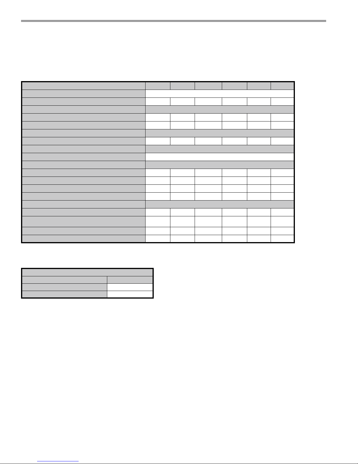
Unit Physical Data
Tranquility®
Model 024 030 036 042 048 060
Compressor (1 Each) Scroll
Factory Charge HFC-410A (oz) 51 48 54 70 80 84
ECM Fan Motor & Blower
Fan Motor (hp) 1/2 1/2 1/2 3/4 3/4 1
Blower Wheel Size (dia x w) - (in) 9X7 9X7 9X8 9X8 10X10 11X10
Water Connection Size
FPT(in) 3/4” 3/4” 3/4” 3/4" 1" 1"
HWG Connection Size
FPT(in) 1/2”
Vertical Upfl ow
Air Coil Dimensions (h x w) - (in) 20 X 17.25 20 X 17.25 24 X 21.75 24 X 21.75 28.75 X 24 28.75 X 24
Standard Filter - 1" [25.4mm] Throwaway, qty (in) 20x20 20x20 24x24 24x24 28x28 28x28
Weight - Operating, (lbs) 224 224 249 260 315 330
Weight - Packaged, (lbs) 229 229 255 266 322 337
Horizontal
Air Coil Dimensions (h x w) - (in) 16 X 22 16 X 22 20 X 25 20 X 25 20 X 35 20 X 35
Standard Filter - 1" [25.4mm] Throwaway, qty (in) 18x25 18x25
Weight - Operating, (lbs) 208 208 233 244 299 314
Weight - Packaged, (lbs) 213 213 239 250 306 321
Notes:
All units have TXV expansion device and 1/2” & 3/4” electrical knockouts.
22 Two-Stage (TZ) Series (60Hz Only)
20x28 or
2-20x14
20x28 or
2-20x14
1-20x24,
1-20x14
1-20x24,
1-20x14
Unit Maximum Water Working Pressure
Options
Internal Pump
Internal Modulating Water Valve (MWV)
Max Pressure PSIG [kPa]
145 [999]
300 [2,068]
6
ClimateMaster Water-Source Heat Pumps
THE SMART SOLUTION FOR ENERGY EFFICIENCY
Horizontal Unit Location
Units are not designed for outdoor installation. Locate
the unit in an INDOOR area that allows enough space
for service personnel to perform typical maintenance or
repairs without removing unit from the ceiling. Horizontal
units are typically installed above a false ceiling or in a
ceiling plenum. Never install units in areas subject to
freezing or where humidity levels could cause cabinet
condensation (such as unconditioned spaces subject
to 100% outside air). Consideration should be given to
access for easy removal of the fi lter and access panels.
Provide suffi cient room to make water, electrical, and
duct connection(s).
If the unit is located in a confi ned space, such as a closet,
provisions must be made for return air to freely enter the
space by means of a louvered door, etc. Any access panel
screws that would be diffi cult to remove after the unit
is installed should be removed prior to setting the unit.
Refer to Figure 3 for an illustration of a typical installation.
Refer to unit submittal data or engineering design guide
for dimensional data.
Conform to the following guidelines when selecting
unit location:
1. Provide a hinged access door in concealed-spline
or plaster ceilings. Provide removable ceiling
tiles in T-bar or lay-in ceilings. Refer to horizontal
unit dimensions for specifi c series and model in
unit submittal data. Size the access opening to
accommodate the service technician during the
removal or replacement of the compressor and the
removal or installation of the unit itself.
2. Provide access to hanger brackets, water valves and
fi ttings. Provide screwdriver clearance to access
panels, discharge collars and all electrical connections.
3. DO NOT obstruct the space beneath the unit with
piping, electrical cables and other items that prohibit
future removal of components or the unit itself.
4. Use a manual portable jack/lift to lift and support the
weight of the unit during installation and servicing.
Tranquility
®
22 (TZ) Series
Revised: 01/21/13
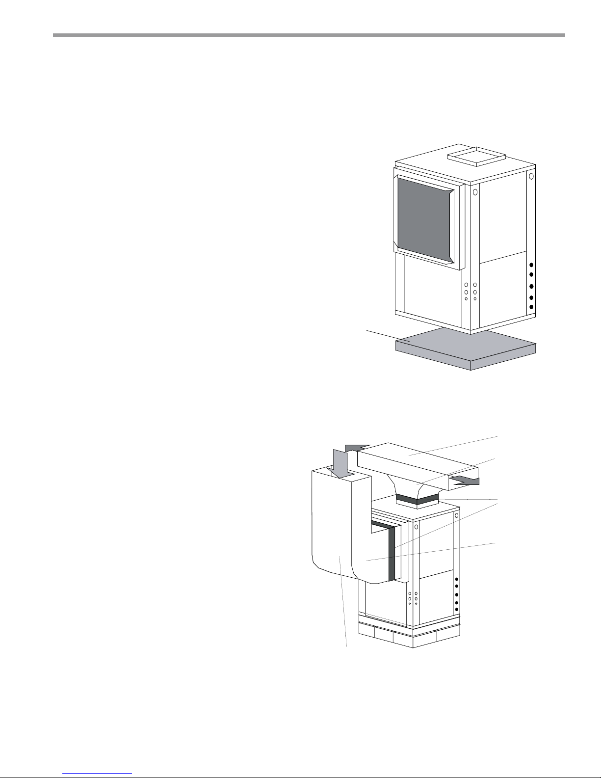
Horizontal Installation
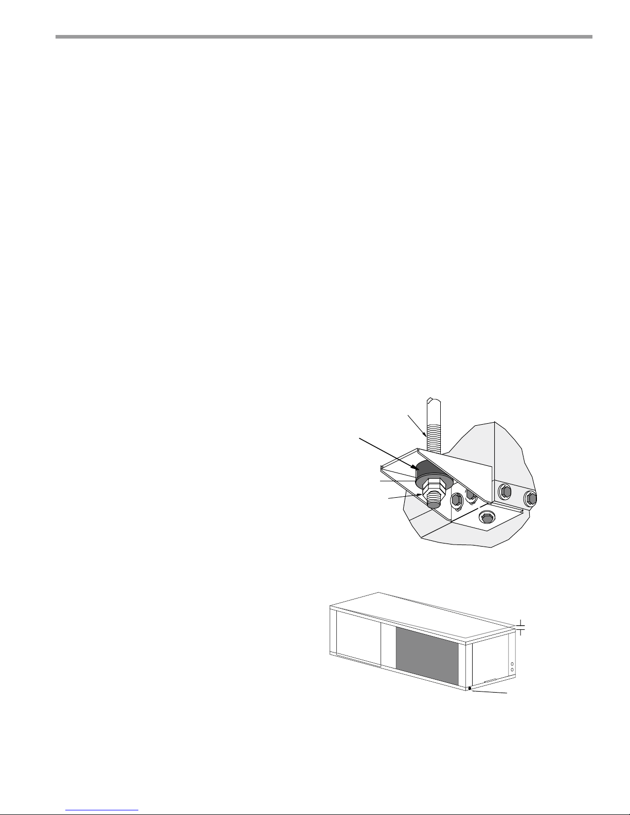
Mounting Horizontal Units
Horizontal units have hanger kits pre-installed from the
factory as shown in Figure 1. Figure 3 shows a typical
horizontal unit installation.
Horizontal heat pumps are typically suspended above
a ceiling or within a soffi t using fi eld supplied, threaded
rods sized to support the weight of the unit.
Use four (4) fi eld supplied threaded rods and factory
provided vibration isolators to suspend the unit. Hang
the unit clear of the fl oor slab above and support the
unit by the mounting bracket assemblies only. DO NOT
attach the unit fl ush with the fl oor slab above.
Pitch the unit toward the drain as shown in Figure 2 to
improve the condensate drainage. On small units (less
than 2.5 tons/8.8kW) ensure that unit pitch does not
cause condensate leaks inside the cabinet.
Figure 1: Hanger Bracket
>PP@7KUHDGHG
5RGE\RWKHUV
9LEUDWLRQ,VRODWRU
IDFWRU\VXSSOLHG
:DVKHU
E\RWKHUV
'RXEOH+H[1XWV
E\RWKHUV
Figure 2: Horizontal Unit Pitch
1/4” (6.4mm) pitch
per foot for drainage
The installation of water source heat pump units and all
associated components, parts and accessories which
make up the installation shall be in accordance with
the regulations of ALL authorities having jurisdiction
and MUST conform to all applicable codes. It is the
responsibility of the installing contractor to determine
and comply with ALL applicable codes and regulations.
climatemaster.com
Drain Connection
7
CLIMATEMASTER WATER-SOURCE HEAT PUMPS
Tranquility
Revised: 01/21/13
®
22 (TZ) Series
Horizontal Installation
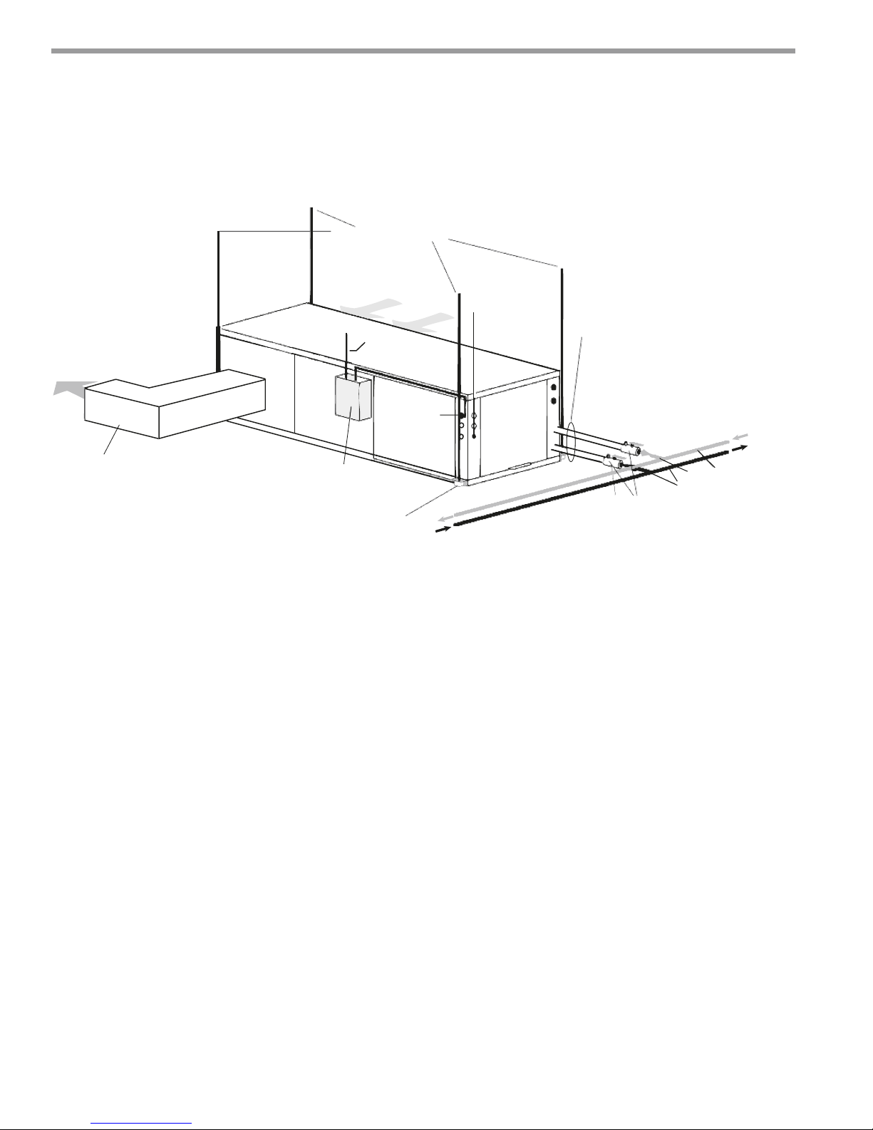
Figure 3: Typical Horizontal Unit Installation
Suppy Air
Insulated supply duct with
at least on 90 deg. elbow
to reduce air noise
Unit Power
Disconnect
Power Wiring
3/8” [10mm] thread rods
(by others)
Unit Power
Unit Hanger Kits
(included)
Thermostat
Wiring
Stainless Steel
Braid Hose with
Integral “J” Swivel
Ball valve with optional
integral P/T plug
Building
Loop
Water out
Water in
Air Coil - To obtain maximum performance, the air coil
should be cleaned before start-up. A 10% solution of
dishwasher detergent and water is recommended for
both sides of the coil. A thorough water rinse should
follow. UV based anti-bacterial systems may damage
coated air coils.
Notice! Installation Note - Ducted Return: Many
horizontal WSHPs are installed in a return air ceiling
plenum application (above ceiling). Vertical WSHPs are
commonly installed in a mechanical room with free return
(e.g. louvered door). Therefore, fi lter rails are the industry
standard and are included on ClimateMaster commercial
heat pumps for the purposes of holding the fi lter only.
For ducted return applications, the fi lter rail must be
removed and replaced with a duct fl ange or fi lter rack.
Canvas or fl exible connectors should also be used to
minimize vibration between the unit and ductwork.
8
ClimateMaster Water-Source Heat Pumps
THE SMART SOLUTION FOR ENERGY EFFICIENCY
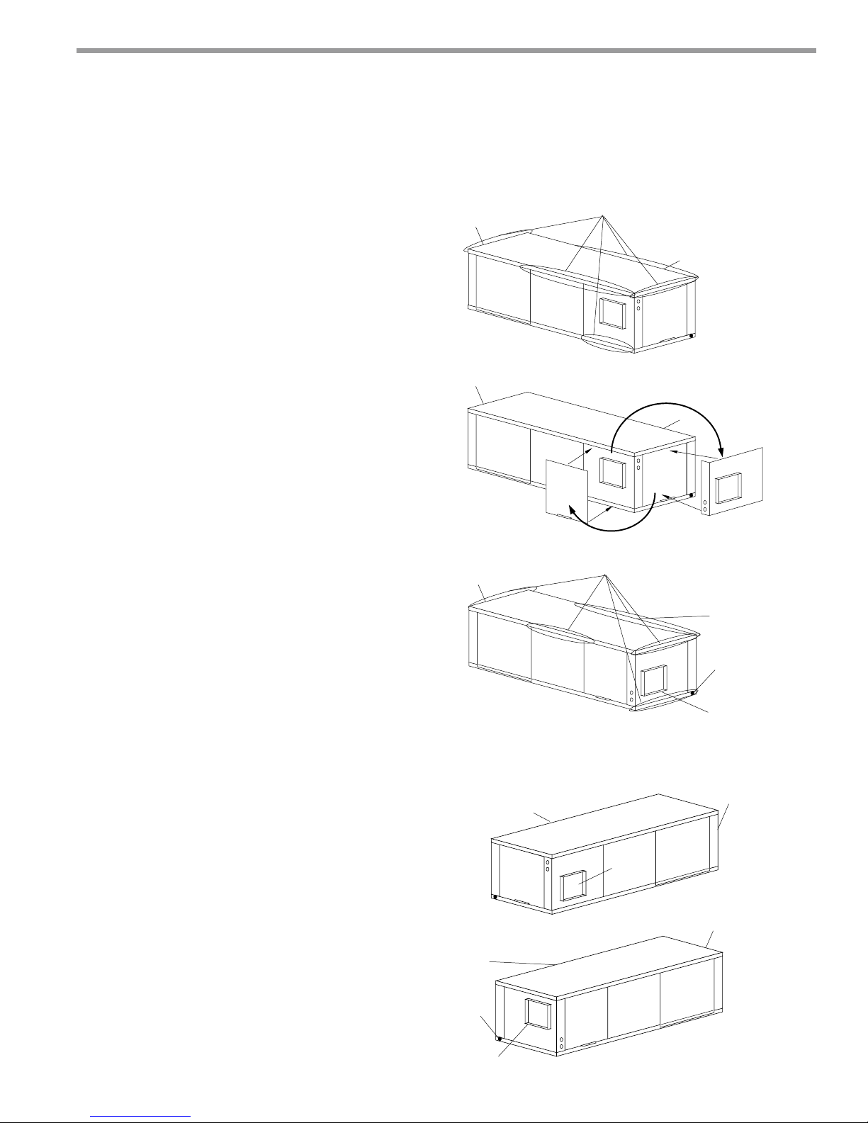
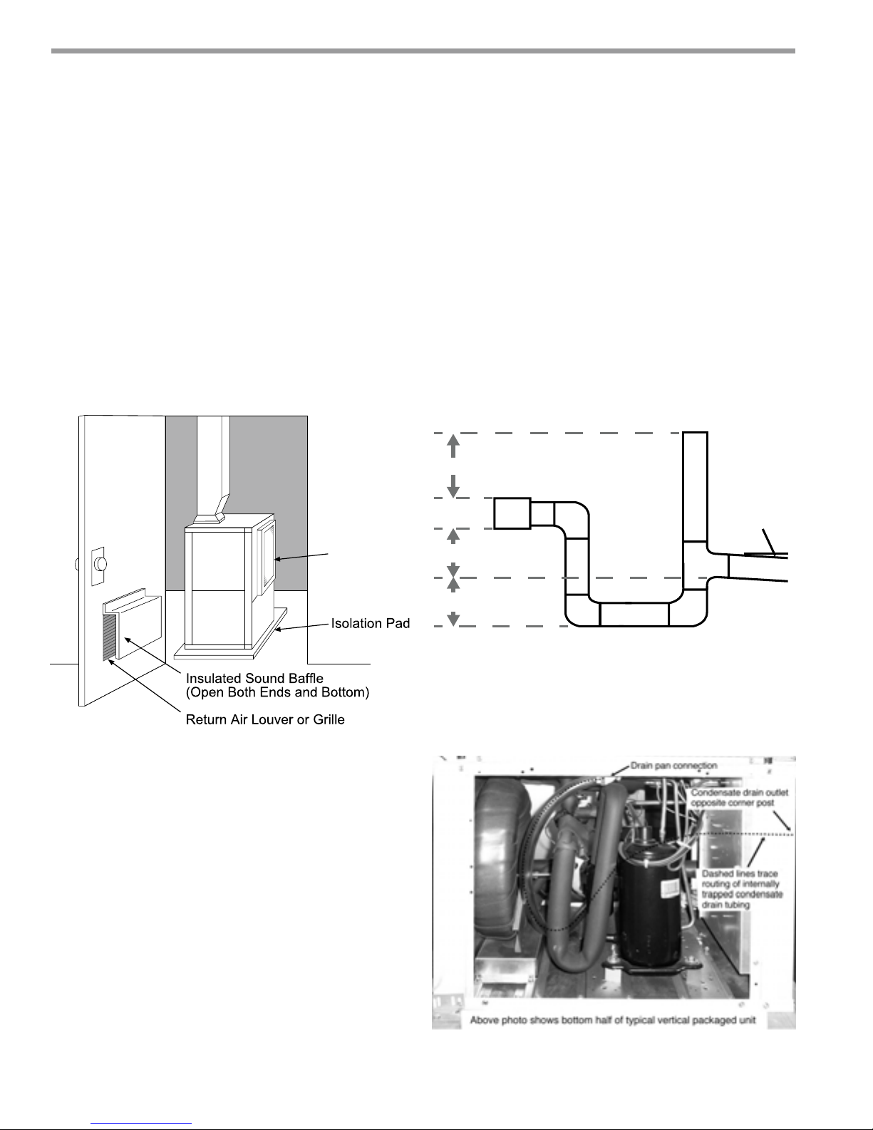
Overview - Horizontal units can be fi eld converted
between side (straight) and back (end) discharge using
the instructions below.
Note: It is not possible to fi eld convert return air
between left or right return models due to the
necessity of refrigeration copper piping changes.
Preparation - It is best to fi eld convert the unit on the
ground before hanging. If the unit is already hung it
should be taken down for the fi eld conversion.
Side to Back Discharge Conversion
1. Place unit in well lit area. Remove the screws as shown
in Figure 4 to free top panel and discharge panel.
2. Lift out the access panel and set aside. Lift and rotate
the discharge panel to the other position as shown,
being careful with the blower wiring.
3. Check blower wire routing and connections for
tension or contact with sheet metal edges. Re-route if
necessary.
4. Check refrigerant tubing for contact with other
components.
5. Reinstall top panel and screws noting that the location
for some screws will have changed.
6. Manually spin the fan wheel to ensure that the wheel
is not rubbing or obstructed.
7. Replace access panels.
Tranquility
Field Conversion of Air Discharge
Figure 4: Left Return Side to Back
Water
Connection End
Water
Connection End
Water
Connection End
Side Discharge
Remove Screws
Rotate
Move to Side
Replace Screws
®
22 (TZ) Series
Revised: 01/21/13
Return Air
Return Air
Return Air
Back to Side Discharge Conversion - If the discharge is
changed from back to side, use above instruction noting
that illustrations will be reversed.
Left vs. Right Return - It is not possible to fi eld convert
return air between left or right return models due to
the necessity of refrigeration copper piping changes.
However, the conversion process of side to back or
back to side discharge for either right or left return
confi guration is the same. In some cases, it may be
possible to rotate the entire unit 180 degrees if the return
air connection needs to be on the opposite side. Note
that rotating the unit will move the piping to the
other end of the unit.
Back Discharge
Figure 5: Right Return Side to Back
Return Air
Supply Duct
Side Discharge
Return Air
Drain
Discharge Air
Back Discharge
Drain
Discharge Air
Water
Connection End
Water
Connection End
climatemaster.com
9
CLIMATEMASTER WATER-SOURCE HEAT PUMPS
C
n
Tranquility
Revised: 01/21/13
®
22 (TZ) Series
ondensate Piping
Duct System Installatio
Horizontal Installation
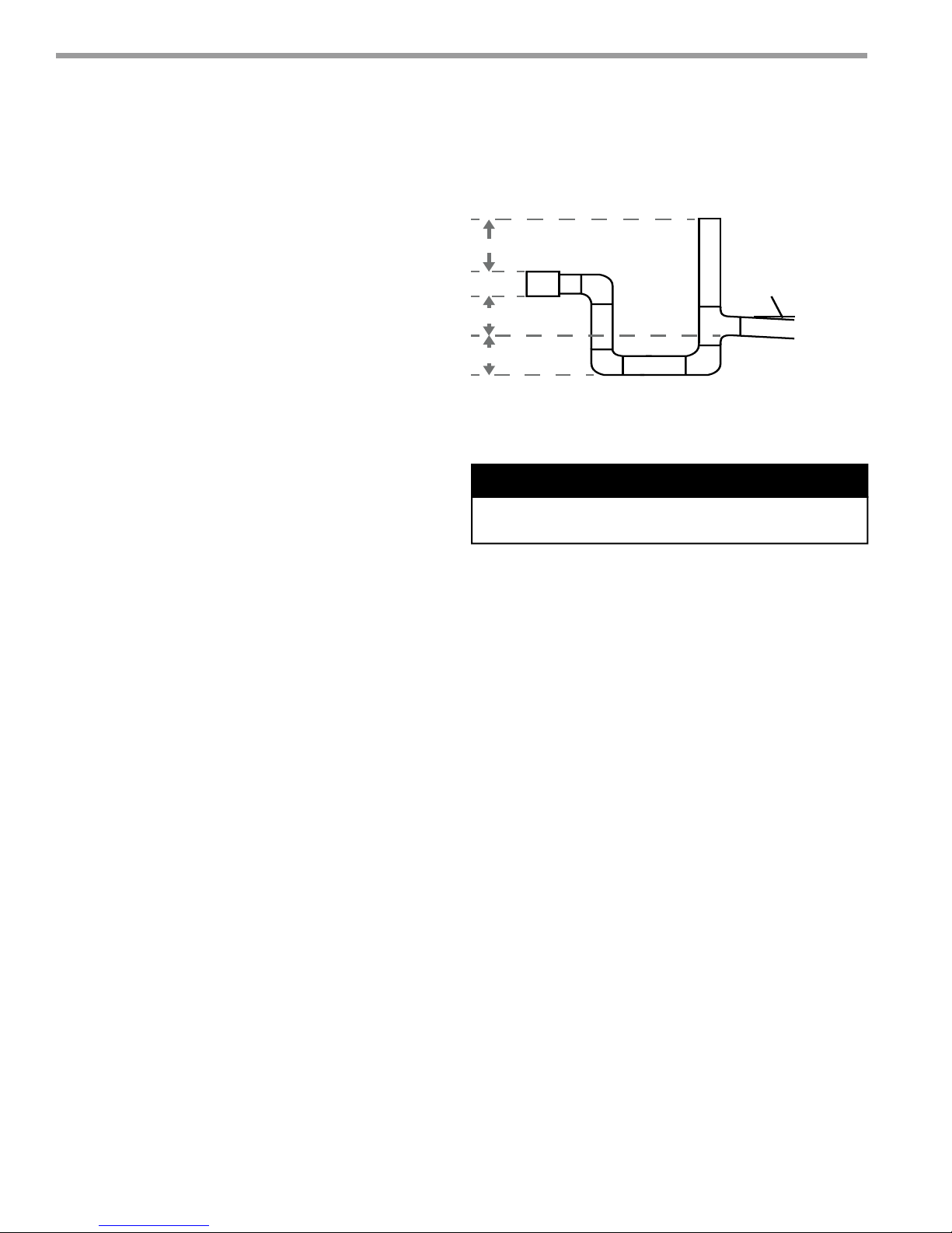
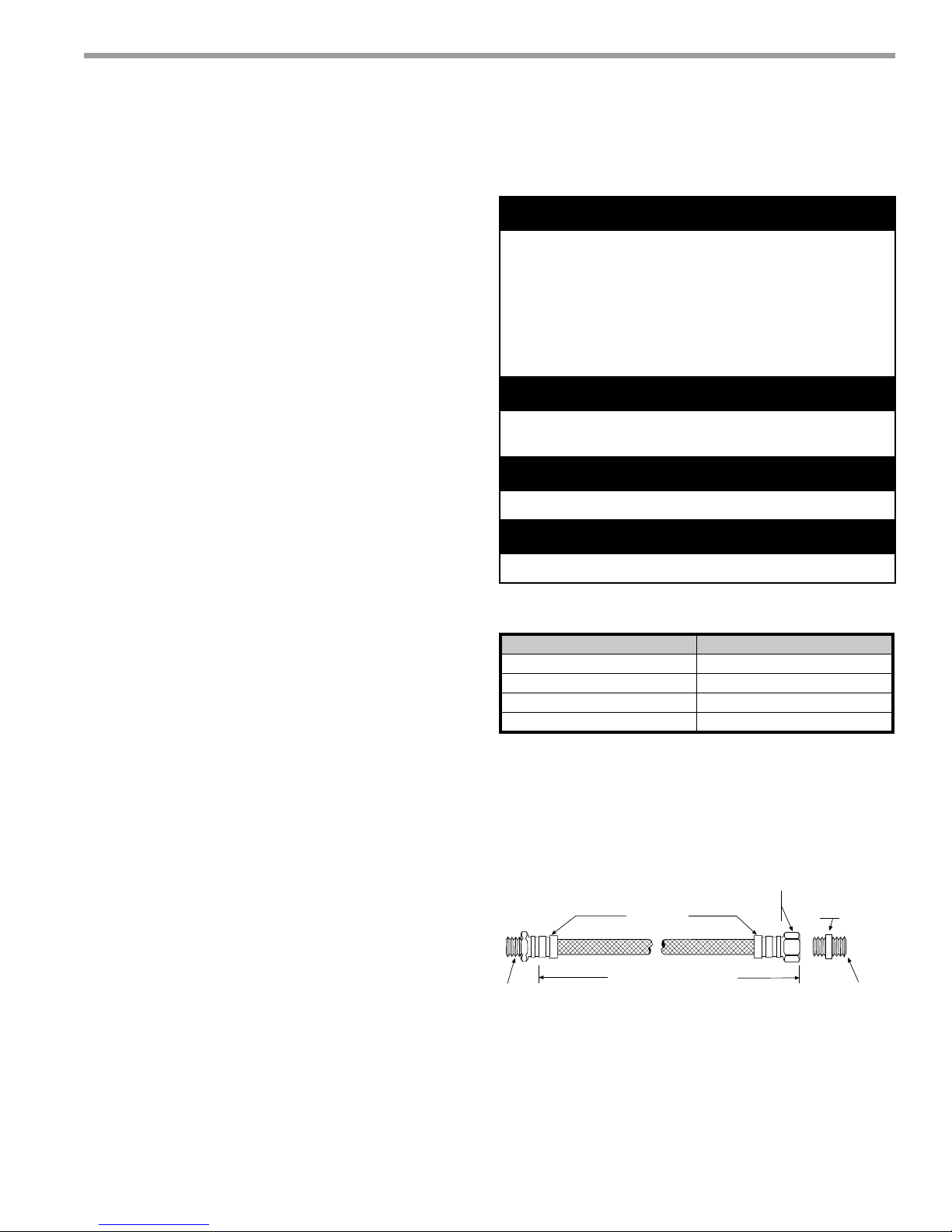
Condensate Piping - Horizontal Units - A condensate
drain line must be installed and pitched away for the unit
to allow for proper drainage. This connection must meet
all local plumbing/building codes.
Pitch the unit toward the drain as shown in Figure 2 to
improve the condensate drainage. On small units (less
than 2.5 tons/8.8 kW), ensure that unit pitch does not
cause condensate leaks inside the cabinet.
Install condensate trap at each unit with the top of
the trap positioned below the unit condensate drain
connection as shown in Figure 6. Design the depth of
the trap (water-seal) based upon the amount of ESP
capability of the blower (where 2 inches [51mm] of ESP
capability requires 2 inches [51mm] of trap depth).
As a general rule, 1-1/2 inch [38mm] trap depth is the
minimum.
Each unit must be installed with its own individual trap
and connection to the condensate line (main) or riser.
Provide a means to fl ush or blow out the condensate line.
DO NOT install units with a common trap and/or vent.
Figure 6: Horizontal Condensate Connection
ರ
ರ3HU
)RRW
ರ
ರ
* Some units include a painted drain connection.
Using a threaded pipe or similar device to clear
any excess paint accumulated inside this fitting
may ease final drain line installation.
CAUTION!
CAUTION! Ensure condensate line is pitched toward drain
1/8 inch per ft [11mm per m] of run.
Always vent the condensate line when dirt or air
can collect in the line or a long horizontal drain line
is required. Also vent when large units are working
against higher external static pressure than other units
connected to the same condensate main since this may
cause poor drainage for all units on the line. WHEN A
VENT IS INSTALLED IN THE DRAIN LINE, IT MUST BE
LOCATED AFTER THE TRAP IN THE DIRECTION OF
THE CONDENSATE FLOW.
Duct System Installation - Proper duct sizing and design
is critical to the performance of the unit. The duct system
should be designed to allow adequate and even airfl ow
through the unit during operation. Air fl ow through
the unit MUST be at or above the minimum stated
airfl ow for the unit to avoid equipment damage. Duct
systems should be designed for quiet operation. Refer
to Figure 3 for horizontal duct system details or Figure
8 for vertical duct system details. A fl exible connector
is recommended for both discharge and return air duct
connections on metal duct systems to eliminate the
transfer of vibration to the duct system. To maximize
sound attenuation of the unit blower, the supply and
return plenums should include internal fi berglass duct
liner or be constructed from ductboard for the fi rst few
feet. Application of the unit to uninsulated ductwork in an
unconditioned space is not recommended, as the unit’s
performance may be adversely affected.
10
At least one 90° elbow should be included in the supply
duct to reduce air noise. If air noise or excessive air fl ow
is a problem, the blower speed can be changed. For
airfl ow charts, consult submittal data for the series and
model of the specifi c unit.
If the unit is connected to existing ductwork, a previous
check should have been made to ensure that the
ductwork has the capacity to handle the airfl ow required
for the unit. If ducting is too small, as in the replacement
of a heating only system, larger ductwork should be
installed. All existing ductwork should be checked for
leaks and repaired as necessary.
ClimateMaster Water-Source Heat Pumps
THE SMART SOLUTION FOR ENERGY EFFICIENCY
on
Vertical Unit Location - Units are not designed for
outdoor installation. Locate the unit in an INDOOR
area that allows enough space for service personnel to
perform typical maintenance or repairs without removing
unit from the mechanical room/closet. Vertical units
are typically installed in a mechanical room or closet.
Never install units in areas subject to freezing or where
humidity levels could cause cabinet condensation (such
as unconditioned spaces subject to 100% outside air).
Consideration should be given to access for easy removal
of the fi lter and access panels. Provide suffi cient room to
make water, electrical, and duct connection(s).
If the unit is located in a confi ned space, such as a closet,
provisions must be made for return air to freely enter
the space by means of a louvered door, etc. Any access
panel screws that would be diffi cult to remove after
the unit is installed should be removed prior to setting
the unit. Refer to Figures 7 and 8 for typical installation
illustrations. Refer to unit submittal data or engineering
design guide for dimensional data.
Tranquility
Vertical Unit Locati
Figure 7: Vertical Unit Mounting
$LU3DGRUH[WUXGHG
SRO\VW\UHQHLQVXODWLRQERDUG
®
22 (TZ) Series
Revised: 01/21/13
Vertical Installation
1. Install the unit on a piece of rubber, neoprene orother
mounting pad material for sound isolation. The pad
should be at least 3/8” [10mm] to 1/2” [13mm] in
thickness. Extend the pad beyond all four edges of
the unit.
2. Provide adequate clearance for fi lter replacement
and drain pan cleaning. Do not block fi lter access
with piping, conduit or other materials. Refer to
unit submittal data or engineering design guide for
dimensional data.
3. Provide access for fan and fan motor maintenance
and for servicing the compressor and coils without
removing the unit.
4. Provide an unobstructed path to the unit within the
closet or mechanical room. Space should be suffi cient
to allow removal of the unit, if necessary.
5. Provide access to water valves and fi ttings and
screwdriver access to the unit side panels, discharge
collar and all electrical connections.
Notice! Installation Note - Ducted Return: Many
horizontal WSHPs are installed in a return air ceiling
plenum application (above ceiling). Vertical WSHPs are
commonly installed in a mechanical room with free return
(e.g. louvered door). Therefore, fi lter rails are the industry
standard and are included on ClimateMaster commercial
heat pumps for the purposes of holding the fi lter only.
For ducted return applications, the fi lter rail must be
removed and replaced with a duct fl ange or fi lter rack.
Canvas or fl exible connectors should also be used to
minimize vibration between the unit and ductwork.
Figure 8: Typical Vertical Unit Installation Using
Ducted Return Air
Internally insulate return
transition duct to reduce
noise
climatemaster.com
Rev.: 6/2/09S
Internally insulate supply
duct for first 1.2 m each way
to reduce noise
Use turning vanes in
supply transition
Flexible canvas duct
connector to reduce
noise and vibration
Rounded return
transition
11
CLIMATEMASTER WATER-SOURCE HEAT PUMPS
Tranquility
Revised: 01/21/13
®
22 (TZ) Series
Vertical Installation
Sound Attenuation for Vertical Units - Sound
attenuation is achieved by enclosing the unit within a
small mechanical room or a closet. Additional measures
for sound control include the following:
1. Mount the unit so that the return air inlet is 90° to the
return air grille. Refer to Figure 9. Install a sound baffl e
as illustrated to reduce line-of sight sound transmitted
through return air grilles.
2. Mount the unit on a rubber or neoprene isolation pad
to minimize vibration transmission to the building
structure.
Figure 9: Vertical Sound Attenuation
Condensate Piping for Vertical Units - A condensate
line must be installed and pitched away from the unit to
allow for proper drainage. This connection must meet
all local plumbing/building codes. Vertical units utilize
a condensate hose inside the cabinet as a trapping
loop; therefore an external trap is not necessary. Figure
10a shows typical condensate connections. Figure 10b
illustrates the internal trap for a typical vertical heat
pump. Each unit must be installed with its own individual
vent (where necessary) and a means to fl ush or blow
out the condensate drain line. Do not install units with a
common trap and/or vent.
Figure 10a: Vertical Condensate Drain
ರ
Return
Air Inlet
Notice! Units with clear plastic drain lines should
have regular maintenance (as required) to avoid
buildup of debris, especially in new construction.
ರ3HU
)RRW
ರ
ರ
* Some units include a painted drain connection.
Using a threaded pipe or similar device to clear
any excess paint accumulated inside this fitting
may ease final drain line installation.
Figure 10b: Vertical Internal Condensate Trap
12
ClimateMaster Water-Source Heat Pumps
THE SMART SOLUTION FOR ENERGY EFFICIENCY
Installation of Supply and Return Piping
Follow these piping guidelines.
1. Install a drain valve at the base of each supply and
return riser to facilitate system fl ushing.
2. Install shut-off / balancing valves and unions at each
unit to permit unit removal for servicing.
3. Place strainers at the inlet of each system circulating
pump.
4. Select the proper hose length to allow slack between
connection points. Hoses may vary in length by +2%
to -4% under pressure.
5. Refer to Table 1. Do not exceed the minimum bend
radius for the hose selected. Exceeding the minimum
bend radius may cause the hose to collapse, which
reduces water fl ow rate. Install an angle adapter to
avoid sharp bends in the hose when the radius falls
below the required minimum.
Tranquility
®
22 (TZ) Series
Revised: 01/21/13
Piping Installation
WARNING!
WARNING! Polyolester Oil, commonly known as POE oil, is
a synthetic oil used in many refrigeration systems including
those with HFC-410A refrigerant. POE oil, if it ever comes
in contact with PVC or CPVS piping, may cause failure of
the PVC/CPVC. PVC/CPVC piping should never be used
as supply or return water piping with water source heat
pump products containing HFC-410A as system failures and
property damage may result.
CAUTION!
CAUTION! Corrosive system water requires corrosion
resistant fi ttings and hoses, and may require water treatment.
CAUTION!
CAUTION! Do not bend or kink supply lines or hoses.
Insulation is not required on loop water piping except
where the piping runs through unheated areas, outside
the building or when the loop water temperature is
below the minimum expected dew point of the pipe
ambient conditions. Insulation is required if loop water
temperature drops below the dew point (insulation is
required for ground loop applications in most climates).
Pipe joint compound is not necessary when Tefl on®
thread tape is pre-applied to hose assemblies or when
fl ared-end connections are used. If pipe joint compound
is preferred, use compound only in small amounts on
the external pipe threads of the fi tting adapters. Prevent
sealant from reaching the fl ared surfaces of the joint.
Note: When antifreeze is used in the loop, ensure that
it is compatible with the Tefl on® tape or pipe joint
compound that is applied.
Maximum allowable torque for brass fi ttings is 30 ft-lbs
[41 N-m]. If a torque wrench is not available, tighten
fi nger-tight plus one quarter turn. Tighten steel fi ttings
as necessary.
Optional pressure-rated hose assemblies designed
specifi cally for use with ClimateMaster units are available.
Similar hoses can be obtained from alternate suppliers.
Supply and return hoses are fi tted with swivel-joint fi ttings
at one end to prevent kinking during installation.
CAUTION!
CAUTION! Piping must comply with all applicable codes.
Table 1: Metal Hose Minimum Bend Radii
Hose Diameter Minimum Bend Radii
1/2" [12.7mm] 2-1/2" [6.4cm]
3/4" [19.1mm] 4" [10.2cm]
1" [25.4mm] 5-1/2" [14cm]
1-1/4" [31.8mm] 6-3/4" [17.1cm]
NOTICE! Do not allow hoses to rest against structural
building components. Compressor vibration may
be transmitted through the hoses to the structure,
causing unnecessary noise complaints.
Figure 11: Supply/Return Hose Kit
MPT
Rib Crimped
Length
(2 ft [0.6m] Length Standard)
Swivel
Brass
Fitting
Brass
Fitting
MPT
climatemaster.com
13
CLIMATEMASTER WATER-SOURCE HEAT PUMPS
Tranquility
Revised: 01/21/13
®
22 (TZ) Series
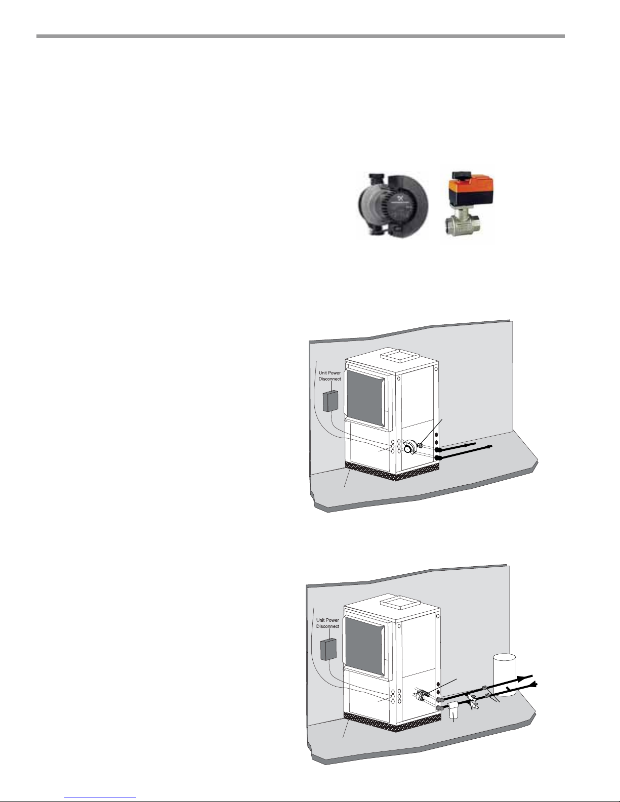
vFlow™ Heat Pump Applications Overview
vFlow™ is a revolutionary new, intelligent, and effi cient way
to circulate water (or water plus antifreeze) using internal,
variable speed water fl ow control. The factory installed
high effi ciency variable speed pumps uses almost half
the wattage of traditional fi xed speed pump. vFlow™
technology improves the life expectancy of the unit by
reducing the amount of energy required to optimize the
fl ow of water throughout the system and also reduces the
space, cost, and labor required to install external water fl ow
control mechanisms (fl ow controllers, solenoid and fl ow
control valves).
vFlow™ Confi gurations:
1. Low System Pressure Drop Modulating Motorized
Valve – Typical for External Central Pumping.
Primarily for use on multi-unit applications with central
pumping. With this option the unit includes a low
pressure drop, high Cv modulating motorized water
valve that is controlled by the DXM2 control based
on the difference in the entering and leaving water
temperature delta T.
This valve is a standard factory installed feature for the
TZ unit.
2. High System Pressure Drop Modulating Motorized
Valve – Typical for High Pressure Water System such
as Water Well Pumps.
With this option the unit includes a high pressure
drop modulating water valve that is controlled by the
DXM2 control based on the difference in the entering
and leaving water temperature delta T. A low Cv valve
is used to provide more precise control against high
system pressure differential type of loops. This valve
is a factory installed option for the TZ unit and when
selected replaces the modulating valve.
3. Standard Head Variable Pump – Typical for Multiple
Unit Central Pumping.
With this option the unit includes an internal variable
speed pump that is best suited to low pressure drop
systems such as primary/secondary pumping. The
pump speed is controlled by the DXM2 control based
on the difference in the entering and leaving water
temperature delta T. This pump includes an internal
check valve for multiple unit installations.
This pump is a factory installed option for the TZ unit
and when selected replaces the modulating valve.
4. High Head Variable Pump – Typical for Individual
Unit Pumping.
With this option the unit includes an internal variable
speed pump that is capable of higher system pressure
drops. The pump speed is controlled by the DXM2
control based on the difference in the entering and
leaving water temperature delta T. This pump includes
14
ClimateMaster Water-Source Heat Pumps
an internal check valve for multiple unit installations.
This pump is a factory installed option for the TZ unit
and when selected replaces the modulating valve.
Variable speed pump or motorized modulating valve delivers variable
water-fl ow, controlled by DXM2 control, based on loop water ∆T.
Typical Closed-Loop Application (with Internal
Variable Pump Shown)
To Thermostat
Internal Variable
Pump
Water Out
High and
Low Voltage
Knockouts
Vibration Isolation Pad
Water In
Typical Open Loop Application (with Internal
Modulating Motorized Valve Shown)
For use on applications using external source for fl ow.
To Thermostat
Pressure
Tank
Shut Off
Ball Valves
for Isolation
Water Out
Water In
High and
Low Voltage
Knockouts
Vibration Isolation Pad
Internal Motorized
Modulating Valve
Boiler
Drains
Optional
Filter
THE SMART SOLUTION FOR ENERGY EFFICIENCY
U
vFlow™ Heat Pump Applications Overview - Continued
Water Pressure Schrader Ports
The pressure ports built in to the unit are provided as a
means of measuring pressure drop through the water-torefrigerant heat exchanger. The water pressure ports are
schrader ports smaller than refrigerant schrader ports.
They are the same size as tire schrader ports. A digital
pressure gauge is recommended for taking pressure
Low System Pressure Drop Valve
Model CV MOPD
024
030
036
042
048
060
4.7 200 3.0 0.41 0.94
4.7 200 4.5 0.92 2.12
4.7 200 6.0 1.63 3.76
4.7 200 3.8 0.65 1.51
4.7 200 5.6 1.42 3.28
4.7 200 7.5 2.55 5.88
4.7 200 4.5 0.92 2.12
4.7 200 6.8 2.09 4.84
4.7 200 9.0 3.67 8.47
4.7 200 5.3 1.27 2.94
4.7 200 7.9 2.83 6.53
4.7 200 10.5 4.99 11.53
4.7 200 6.0 1.63 3.76
4.7 200 9.0 3.67 8.47
4.7 200 12.0 6.52 15.06
7.4 200 7.0 .89 2.06
7.4 200 10.5 2.01 4.64
7.4 200 14.0 3.58 8.26
WPD Adders
GPM PSI FT
High System Pressure Drop Valve
Model CV MOPD
024
030
036
042
048
060
Tranquility
®
22 (TZ) Series
Revised: 01/21/13
readings through these ports. The water fl ow through
the unit can be determined by measuring the water
pressure at the “water pressure out” port and subtracting
it from the water pressure at the “water pressure in” port.
Comparing the pressure differential to the pressure drop
table (wpd)/fl ow rate in Tables 15a through 15d in this
manual will determine the fl ow rate through the unit.
WPD Adders
GPM PSI FT
4.7 200 3.0 0.41 0.94
4.7 200 4.5 0.92 2.12
4.7 200 6.0 1.63 3.76
7.4 200 3.8 0.26 0.61
7.4 200 5.6 0.57 1.32
7.4 200 7.5 1.03 2.37
7.4 200 4.5 0.37 0.85
7.4 200 6.8 0.84 1.95
7.4 200 9.0 1.48 3.42
10.0 200 5.3 0.28 0.65
10.0 200 7.9 0.62 1.44
10.0 200 10.5 1.10 2.55
10.0 200 6.0 0.36 0.83
10.0 200 9.0 0.81 1.87
10.0 200 12.0 1.44 3.33
19.0 200 7.0 0.14 0.31
19.0 200 10.5 0.31 0.70
19.0 200 14.0 0.54 1.25
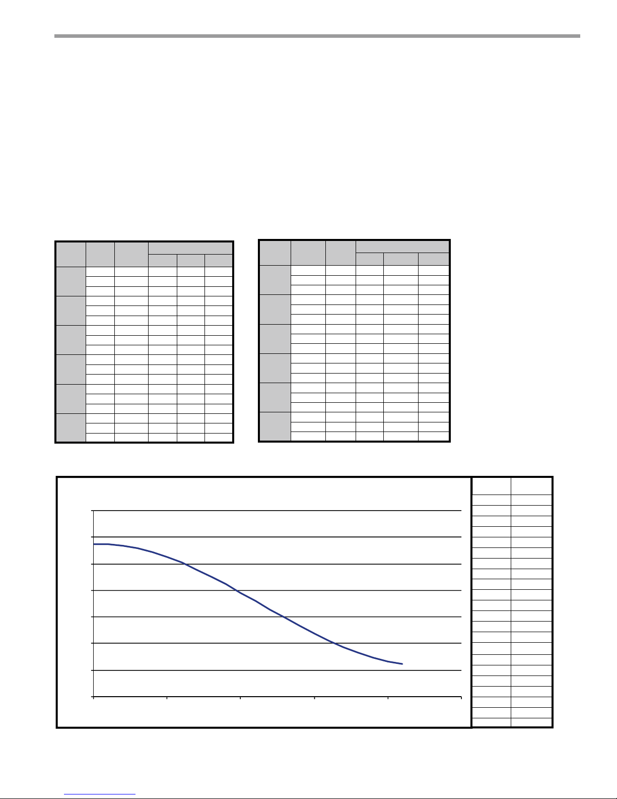
Standard Head Variable Pump Performance
UPM Geo 25-85 Pump Curve
PM Geo 25-85 Pump Curve
35
30
25
20
15
Head (Ft.)
10
5
0
0 5 10 15 20 25
Flow (GPM)
GPM Head (ft)
0.0 28.6
1.0 28.7
2.0 28.4
3.0 27.9
4.0 27.2
5.0 26.3
6.0 25.2
7.0 23.9
8.0 22.6
9.0 21.1
10.0 19.6
11.0 18.0
12.0 16.4
13.0 14.9
14.0 13.3
15.0 11.9
16.0 10.5
17.0 9.3
18.0 8.2
19.0 7.3
20.0 6.6
21.0 6.1
climatemaster.com
15

CLIMATEMASTER WATER-SOURCE HEAT PUMPS
Tranquility
Revised: 01/21/13
®
22 (TZ) Series
High Head Variable Pump Performance
Magna Geo 25-140 Pump Curve
60
50
40
30
Head (Ft.)
20
10
0
0 5 10 15 20 25 30 35 40
Flow (GPM)
GPM Head (ft)
0.0 44.7
1.0 45.4
2.0 46.1
3.0 46.8
4.0 47.5
5.0 47.7
6.0 47.1
7.0 46.1
8.0 45.3
9.0 43.9
10.0 42.6
11.0 41.2
12.0 39.9
13.0 38.7
14.0 37.4
15.0 36.1
16.0 34.9
17.0 33.7
18.0 32.5
19.0 31.3
20.0 30.1
21.0 28.9
22.0 27.8
23.0 26.7
24.0 25.6
25.0 24.5
16
ClimateMaster Water-Source Heat Pumps
THE SMART SOLUTION FOR ENERGY EFFICIENCY
Commercial Water Loop Applications
Commercial systems typically include a number of
units connected to a common piping system. Any unit
plumbing maintenance work can introduce air into the
piping system; therefore air elimination equipment
is a major portion of the mechanical room plumbing.
Consideration should be given to insulating the
piping surfaces to avoid condensation. ClimateMaster
recommends unit insulation any time the water
temperature is expected to be below 60ºF (15.6ºC). Metal
to plastic threaded joints should never be used due to
their tendency to leak over time.
Tefl o n® tape thread sealant is recommended to
minimize internal fouling of the heat exchanger. Do
not over tighten connections and route piping so as
not to interfere with service or maintenance access.
Hose kits are available from ClimateMaster in different
confi gurations for connection between the unit and the
piping system. Depending upon selection, hose kits
may include shut off valves, P/T plugs for performance
measurement, high pressure stainless steel braided hose,
“Y” type strainer with blow down valve, and/or “J” type
swivel connection.
Tranquility
®
22 (TZ) Series
Revised: 01/21/13
Water-Loop Heat Pump Applications
The piping system should be fl ushed to remove dirt,
piping chips, and other foreign material prior to
operation (see “Piping System Cleaning and Flushing
Procedures” in this manual). The fl ow rate is usually set
between 2.25 and 3.5 gpm per ton [2.9 and 4.5 l/m per
kW] of cooling capacity. ClimateMaster recommends 3
gpm per ton [3.9 l/m per kW] for most applications of
water loop heat pumps. To ensure proper maintenance
and servicing, P/T ports are imperative for temperature
and fl ow verifi cation, as well as performance checks.
Water loop heat pump (cooling tower/boiler) systems
typically utilize a common loop, maintained between
60 - 90°F [16 - 32°C]. The use of a closed circuit evaporative
cooling tower with a secondary heat exchanger between
the tower and the water loop is recommended. If an
open type cooling tower is used continuously, chemical
treatment and fi ltering will be necessary.
Typical Water-Loop Application
3/8” [10mm] thread rods
(by others)
Suppy Air
Insulated supply duct with
at least on 90 deg. elbow
to reduce air noise
Unit Power
Disconnect
Power Wiring
Unit Hanger Kits
(included)
Unit Power
Thermostat
Wiring
Stainless Steel
Braid Hose with
Integral “J” Swivel
Ball valve with optional
integral P/T plug
Building
Loop
Water out
Water in
Low Water Temperature Cutout Setting - DXM2 Control
When antifreeze is selected, the LT1 jumper (JW3) should be clipped to select the low temperature (antifreeze 10.0°F
[-12.2°C]) setpoint and avoid nuisance faults (see “Low Water Temperature Cutout Selection” in this manual). Note:
Low water temperature operation requires extended range equipment.
climatemaster.com
17
CLIMATEMASTER WATER-SOURCE HEAT PUMPS
Tranquility
Revised: 01/21/13
®
22 (TZ) Series
Ground-Loop Heat Pump Applications
CAUTION!
CAUTION! The following instructions represent industry
accepted installation practices for closed loop earth coupled
heat pump systems. Instructions are provided to assist the
contractor in installing trouble free ground loops. These
instructions are recommendations only. State/provincial
and local codes MUST be followed and installation MUST
conform to ALL applicable codes. It is the responsibility of
the installing contractor to determine and comply with ALL
applicable codes and regulations.
CAUTION!
CAUTION! Ground loop applications require extended range
equipment and optional refrigerant/water circuit insulation.
Pre-Installation
Prior to installation, locate and mark all existing
underground utilities, piping, etc. Install loops for new
construction before sidewalks, patios, driveways, and other
construction has begun. During construction, accurately
mark all ground loop piping on the plot plan as an aid in
avoiding potential future damage to the installation.
Piping Installation
The typical closed loop ground source system is shown in
Figure 13. All earth loop piping materials should be limited
to polyethylene fusion only for in-ground sections of the
loop. Galvanized or steel fi ttings should not be used at any
time due to their tendency to corrode. All plastic to metal
threaded fi ttings should be avoided due to their potential
to leak in earth coupled applications. A fl anged fi tting
should be substituted. P/T plugs should be used with units
that do not include vFlow so that fl ow can be measured
using the pressure drop of the unit heat exchanger. Units
equipped with any of the four vFlow confi gurations have
built in Schrader ports. Water temperature may be viewed
on the iGate communicating thermostat.
Earth loop temperatures can range between 25 and 110°F
[-4 to 43°C]. Flow rates between 2.25 and 3 gpm [2.41 to
3.23 l/m per kW] of cooling capacity is recommended in
these applications.
Test individual horizontal loop circuits before backfi lling.
Test vertical U-bends and pond loop assemblies prior to
installation. Pressures of at least 100 psi [689 kPa] should
be used when testing. Do not exceed the pipe pressure
rating. Test entire system when all loops are assembled.
Flushing the Earth Loop
Upon completion of system installation and testing, fl ush
the system to remove all foreign objects and purge to
remove all air.
Antifreeze
I
n areas where minimum entering loop temperatures
drop below 40°F [5°C] or where piping will be routed
through areas subject to freezing, antifreeze is required.
Alcohols and glycols are commonly used as antifreeze;
however your local sales offi ce should be consulted to
determine the antifreeze best suited to your area. Freeze
protection should be maintained to 15°F [9°C] below
the lowest expected entering loop temperature. For
example, if 30°F [-1°C] is the minimum expected entering
loop temperature, the leaving loop temperature would
be 22 to 25°F [-6 to -4°C] and freeze protection should be
at 15°F [-10°C]. Calculation is as follows:
30°F - 15°F = 15°F [-1°C - 9°C = -10°C].
All alcohols should be premixed and pumped from
a reservoir outside of the building when possible or
introduced under the water level to prevent fumes.
Calculate the total volume of fl uid in the piping system.
Then use the percentage by volume shown in table
2 for the amount of antifreeze needed. Antifreeze
concentration should be checked from a well mixed
sample using a hydrometer to measure specifi c gravity.
Low Water Temperature Cutout Setting - DXM2
Control
When antifreeze is selected, the LT1 jumper (JW3) should
be clipped to select the low temperature (antifreeze
10.0°F [-12.2°C]) setpoint and avoid nuisance faults (see
“Low Water Temperature Cutout Selection” in this
manual). Note: Low water temperature operation
requires extended range equipment.
Table 2: Antifreeze Percentages by Volume
Type
Methanol
100% USP food grade Propylene Glycol
Ethanol*
* Must not be denatured with any petroleum based product
18
ClimateMaster Water-Source Heat Pumps
Minimum Temperature for Low Temperature Protection
10°F [-12.2°C] 15°F [-9.4°C] 20°F [-6.7°C] 25°F [-3.9°C]
25%
38%
29%
21%
25%
25%
16%
22%
20%
10%
15%
14%
 Loading...