

ClimateMaster Tranquility Water-to-Water THW 008, Tranquility Water-to-Water THW 010, Tranquility Water-to-Water THW 012, Tranquility THW Series Installation Operation & Maintenance
Tranquility®
Water-to-Water
(THW) Series
Residential High
Temperature
Water-to-Water
Geothermal Heat Pumps
(Heating Only) - 50Hz
Installation, Operation
& Maintenance
97B0063N04
Revised: 02 January, 2013
Model Nomenclature 3
General Information 4
Physical Data 5
Dimensional Data 6
Installation 7
Load Plumbing Installation 7
Ground-Water Heat Pump Application 9
Water Quality Standards 10
Ground-Loop Heat Pump Application 11
Electrical - Line Voltage 13
Electrical - Low Voltage 15
Electrical - Controls 17
User Interface 20
Installer Interface 21
Wiring Diagram Matrix 22
Typical Wiring Diagrams 23
CXM Controls 31
Unit Commissioning
& Operating Conditions 33
Unit & System Checkout 34
Unit Start-Up Procedure 35
Preventive Maintenance 36
Warranty 37
Revision History 38
Table of Contents

CLIMATEMASTER WATER-SOURCE HEAT PUMPS
2
ClimateMaster Water-Source Heat Pumps
Tranquility® Water-to-Water THW Series
Revised: 02 January, 2013
This Page Intentionally Left Blank
THE SMART SOLUTION FOR ENERGY EFFICIENCY
3
climatemaster.com
Tranquility® Water-to-Water THW Series
Revised: 02 January, 2013
WARNING!
WARNING!
Safety
Warnings, cautions, and notices appear throughout this
manual. Read these items carefully before attempting
any installation, service, or troubleshooting of the
equipment.
DANGER: Indicates an immediate hazardous situation,
which if not avoided will result in death or serious
injury. DANGER labels on unit access panels must be
observed.
WARNING: Indicates a potentially hazardous situation,
which if not avoided could result in death or serious
injury.
CAUTION: Indicates a potentially hazardous situation
or an unsafe practice, which if not avoided could result
in minor or moderate injury or product or property
damage.
NOTICE: Notifi cation of installation, operation, or
maintenance information, which is important, but which
is not hazard-related.
WARNING!
Model Nomenclature
WARNING! To avoid the release of refrigerant into the
atmosphere, the refrigerant circuit of this unit must be
serviced only by technicians who meet local, state, and
federal profi ciency requirements.
WARNING! All refrigerant discharged from this unit must
be recovered WITHOUT EXCEPTION. Technicians must
follow industry accepted guidelines and all local, state,
and federal statutes for the recovery and disposal of
refrigerants. If a compressor is removed from this unit,
refrigerant circuit oil will remain in the compressor. To
avoid leakage of compressor oil, refrigerant lines of the
compressor must be sealed after it is removed.
WARNING! Units are shipped with R-410A (EarthPure®)
refrigerant. The EarthPure® Application and Service Manual
should be read and understood before attempting to service
refrigerant circuits with R-410A.
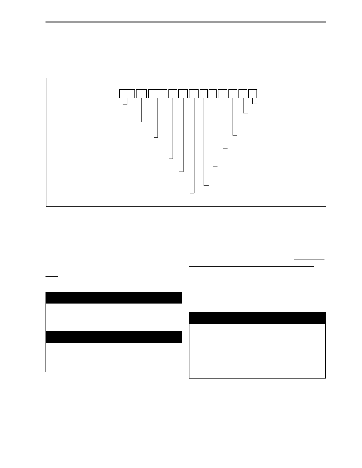
TH W A0 0 8 QT 0 0 C S A S
1 2 3 4 5 6 7
8
9101112 131415
TH = Tranquility High Temperature
Heating Only
Model Type
W = Water-To-Water
Configuration
Unit Size
008
010
Revision Level
A = Current
Voltage
Controls
0 = Residential Standard w/UltraQuiet
Cabinet Insulation
Domestic Hot Water Heating Options
C = Copper Source & Braze Plate Load
Source & Load Water Coil Options
N = Cupro-nickel Source & Braze Plate Load
A = None
Hydronic Options
B = Load Pump W/Expansion Tank
S = Standard
0 = None
Paint Options
S = Stainless Steel & Pewter (Black)
012
1 = 3-Way Valve
C = Load Pump & Source Pump(S)
W/Expansion Tanks
Q = Standard
V = Standard With VSFP
T
= 200-220/50/1 (THW008-010 Only)
S
= 380-420/50/3 (THW012 Only)

CLIMATEMASTER WATER-SOURCE HEAT PUMPS
4
ClimateMaster Water-Source Heat Pumps
Tranquility® Water-to-Water THW Series
Revised: 02 January, 2013
Inspection
Upon receipt of the equipment, carefully check the shipment
against the bill of lading. Make sure all units have been
received. Inspect the carton or crating of each unit, and
inspect each unit for damage. Assure the carrier makes
proper notation of any shortages or damage on all copies of
the freight bill and completes a common carrier inspection
report. Concealed damage not discovered during unloading
must be reported to the carrier within 15 days of receipt of
shipment. If not fi led within 15 days, the freight company can
deny the claim without recourse. Note: It is the responsibility
of the purchaser to fi le all necessary claims with the carrier.
Notify the ClimateMaster Traffi c Department of all damage
within fi fteen (15) days of shipment.
Storage
Equipment should be stored in its shipping carton in a clean,
dry area. Store units in an upright position at all times. Stack
units a maximum of 3 units high.
Unit Protection
Cover units on the job site with either shipping cartons, vinyl
fi lm, or an equivalent protective covering. Cap the open
ends of pipes stored on the job site. In areas where painting,
plastering, and/or spraying has not been completed, all due
precautions must be taken to avoid physical damage to the
units and contamination by foreign material. Physical damage
and contamination may prevent proper start-up and may
result in costly equipment clean-up.
Examine all pipes, fi ttings, and valves before installing any of
the system components. Remove any dirt or trash found in or
on these components.
Pre-Installation
Installation, Operation, and Maintenance instructions are
provided with each unit.. The installation site chosen should
include adequate service clearance around the unit. Before
unit start-up, read all manuals and become familiar with the
unit and its operation. Thoroughly check the system before
operation.
Prepare units for installation as follows:
1. Compare the electrical data on the unit nameplate with
ordering and shipping information to verify that the
correct unit has been shipped.
2. Keep the cabinet covered with the shipping carton until
installation is complete and all plastering, painting, etc.
is fi nished.
3. Verify refrigerant tubing is free of kinks or dents and that
it does not touch other unit components.
4. Inspect all electrical connections. Connections must be
clean and tight at the terminals.
5. Locate and verify any HWG or other accessory sensors
located in the compressor section.
CAUTION!
CAUTION!
General Information
CAUTION! DO NOT store or install units in corrosive
environments or in locations subject to temperature or
humidity extremes (e.g., attics, garages, rooftops, etc.).
Corrosive conditions and high temperature or humidity
can signifi cantly reduce performance, reliability, and
service life. Always move and store units in an upright
position. Tilting units on their sides may cause equipment
damage.
CAUTION! CUT HAZARD - Failure to follow this caution
may result in personal injury. Sheet metal parts may have
sharp edges or burrs. Use care and wear appropriate
protective clothing, safety glasses and gloves when
handling parts and servicing heat pumps.
THE SMART SOLUTION FOR ENERGY EFFICIENCY
5
climatemaster.com
Tranquility® Water-to-Water THW Series
Revised: 02 January, 2013
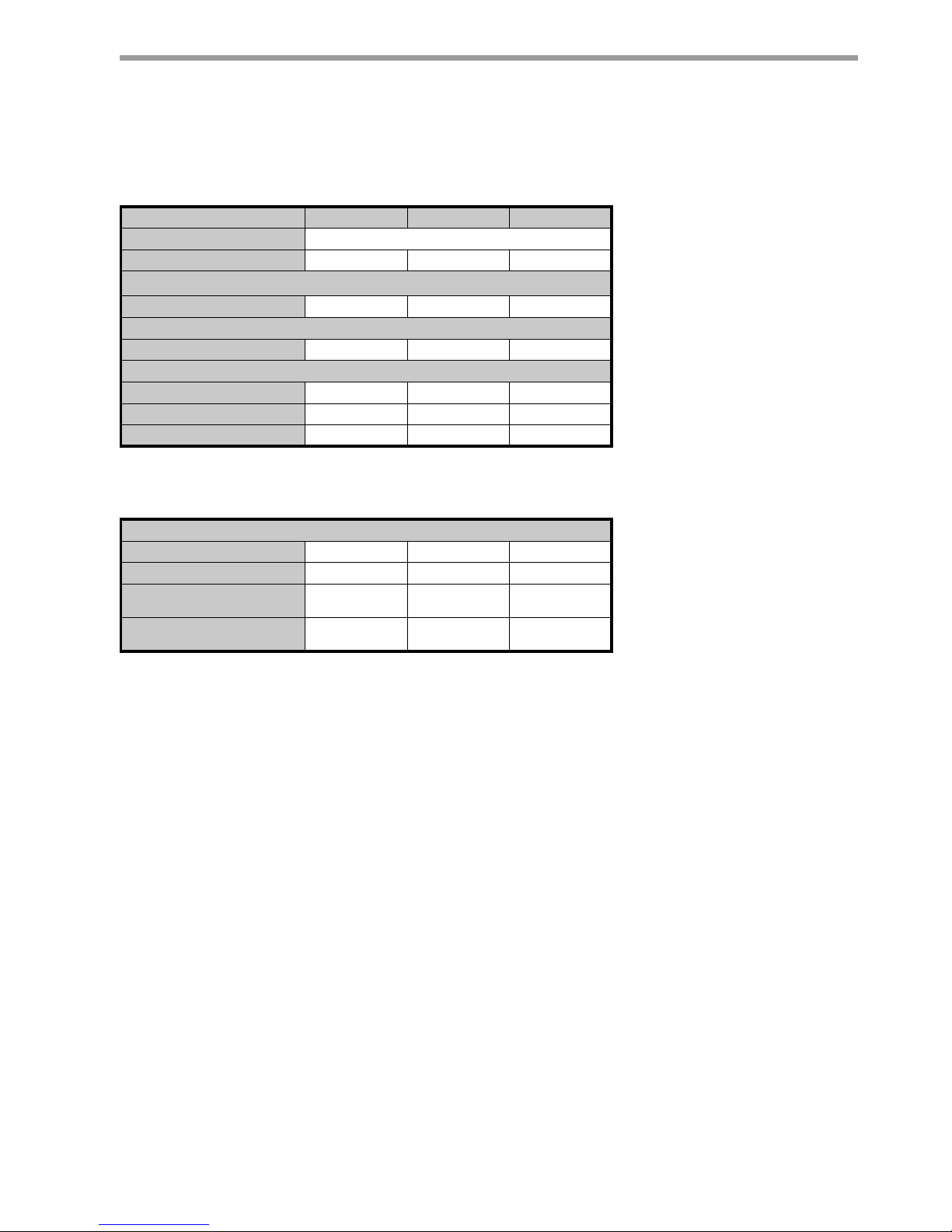
Physical Data
Model 008 010 012
Compressor (qty) Scroll (1)
Factory Charge HFC-410A (kg) 2.51 2.50 2.84
Indoor/Load Water Connection Size
FPT (in) 1 1 1
Outdoor/Source Water Connection Size
FPT (in) 1 1 1
Domestic Hot Water Connection Size
FPT (in) 1 1 1
Weight - Operating, (kg) 207 207 234
Weight - Packaged, (kg) 214 214 241
Dual isolation compressor mounting
Balanced Port Expansion Valve (TXV)
Insulated Source and Load Water Coils
FPT - Female Pipe Thread
Maximum Working Pressure (Water Side)
Base Unit (kPa) 2068 2068 2068
DHW Option (kPa) 2068 2068 2068
Internal Source Pump
w/Expansion Tank (kPa)
310 310 310
Internal Load Pump
w/Expansion Tank (kPa)
310 310 310
CLIMATEMASTER WATER-SOURCE HEAT PUMPS
6
ClimateMaster Water-Source Heat Pumps
Tranquility® Water-to-Water THW Series
Revised: 02 January, 2013
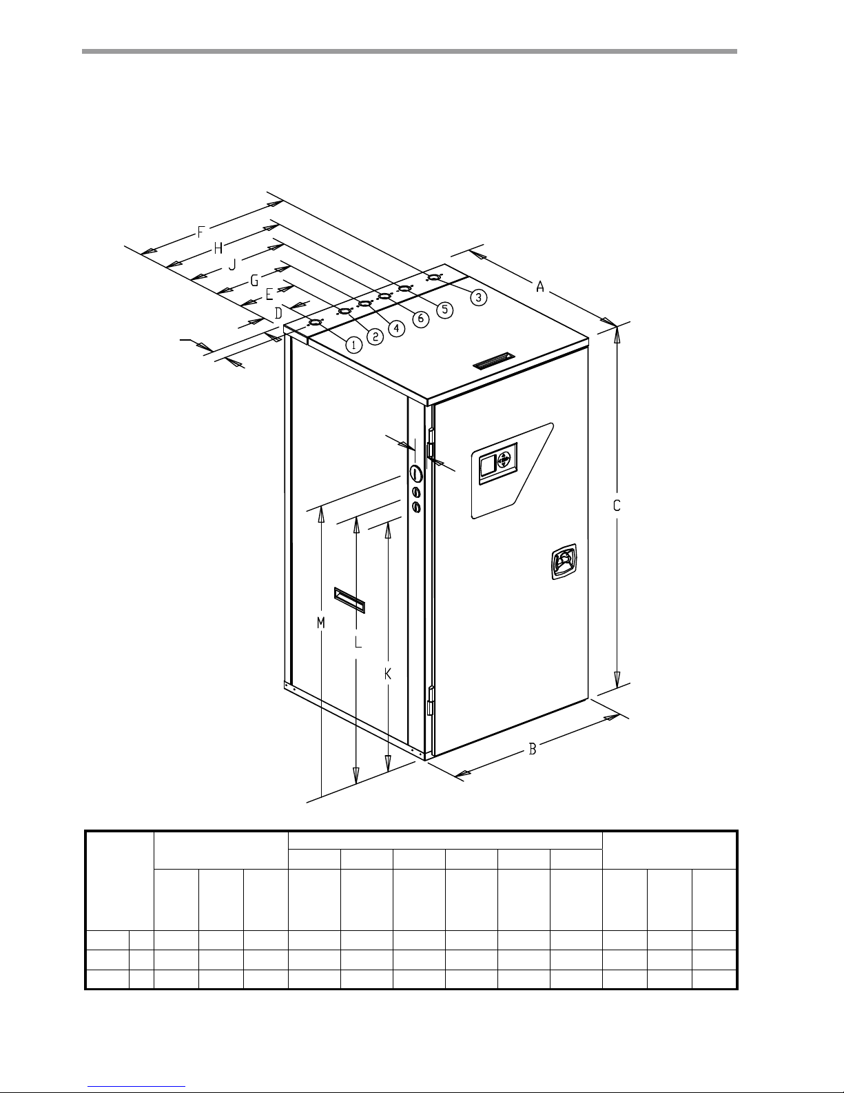
Dimensional Data
Notes:
1. Front, Side, and Top access is preferred for service access.
However, all components may be serviced from the front and
Top access panels if side access is not available.
2. While clear access to all removable panels is not required,
installer should take care to comply with all building codes
and allow adequate clearance for future fi eld service.
Model
Overall Cabinet
Water Connections
Electric Access Plugs
123456
A
DepthBWidthCHeight
D
Source
(Outdoor)
Water In
E
Source
(Outdoor)
Water Out
F
Load
(Indoor)
Water In
G
Load
(Indoor)
Water Out
H
DHW
Return In
J
DHW
Water Out
K
Low
Voltage
L
Low
Voltage
M
Power
Supply
008 cm. 68.1 65.1 124.2 8.6 20.6 56.6 28.7 45.0 36.6 85.3 90.4 96.5
010 cm. 68.1 65.1 124.2 8.6 20.6 56.6 28.7 45.0 36.6 85.3 90.4 96.5
012 cm. 68.1 65.1 124.2 8.6 20.6 56.6 28.7 45.0 36.6 85.3 90.4 96.5
1.9” [4.9cm]
2.1” [5.3cm]
4.9 cm
5.3 cm

THE SMART SOLUTION FOR ENERGY EFFICIENCY
7
climatemaster.com
Tranquility® Water-to-Water THW Series
Revised: 02 January, 2013
The applications are too varied to describe in this
document, however some basic guidelines will be
presented. All plumbing should conform to local codes
and consider the following:
Wide temperature variation applications such as
heating/cooling coils
- Employ piping materials that are rated for the
maximum temperature and pressure combination.
This excludes PVC for most heating applications.
-
Insure load water fl ow in high temperature heating
applications is at least 3.2 l/m per kW to improve
performance and reduce nuisance high pressure
faults.
- DO NOT employ plastic to metal threaded joints
- Utilize a pressure tank and air separator vent system
to equalize pressure and remove air.
Swimming Pool Hot Tub Applications
-
Recommended application includes a brazed plate
heat exchanger to isolate pool water from the unit
heat exchanger.
Potable Water Applications
- Insure load water fl ow in high temperature heating
applications is at least 3.2 l/m per kW to improve
performance and reduce nuisance high pressure
faults.
- A secondary heat exchanger must always be used
between the water-to-water heat pump and potable
water tank. Either an indirect water heat or brazed
plate heat exchanger (with a secondary pump) will
isolate the potable water from the heating water.
Load Plumbing Installation
Installation
THW Unit Location
These units are not designed for outdoor installation.
Locate the unit in an INDOOR area that allows
enough space for service personnel to perform typical
maintenance or repairs.
The installation of water source heat pump units and all
associated components, parts and accessories which
make up the installation shall be in accordance with
the regulations of ALL authorities having jurisdiction
and MUST conform to all applicable codes. It is the
responsibility of the Installing Contractor to determine
and comply with ALL applicable codes and regulations.
Locate the unit in an indoor area that allows easy
removal of access panels, and has enough space for
service personnel to perform maintenance or repair.
Provide suffi cient room to make water and electrical
connections. Any access panel screws that would be
diffi cult to remove after the unit is installed should be
removed prior to setting the unit. These units are not
approved for outdoor installation and, therefore, must
be installed inside the structure being conditioned.
Do not locate in areas where ambient conditions are
not maintained within 4-38°C and up to 75% relative
humidity.
/RDG+;
EU]SOW
,1 287287
+7* '+:
0
'+:
,1
+7*
7R
'+:
6WRUDJH
7DQ N
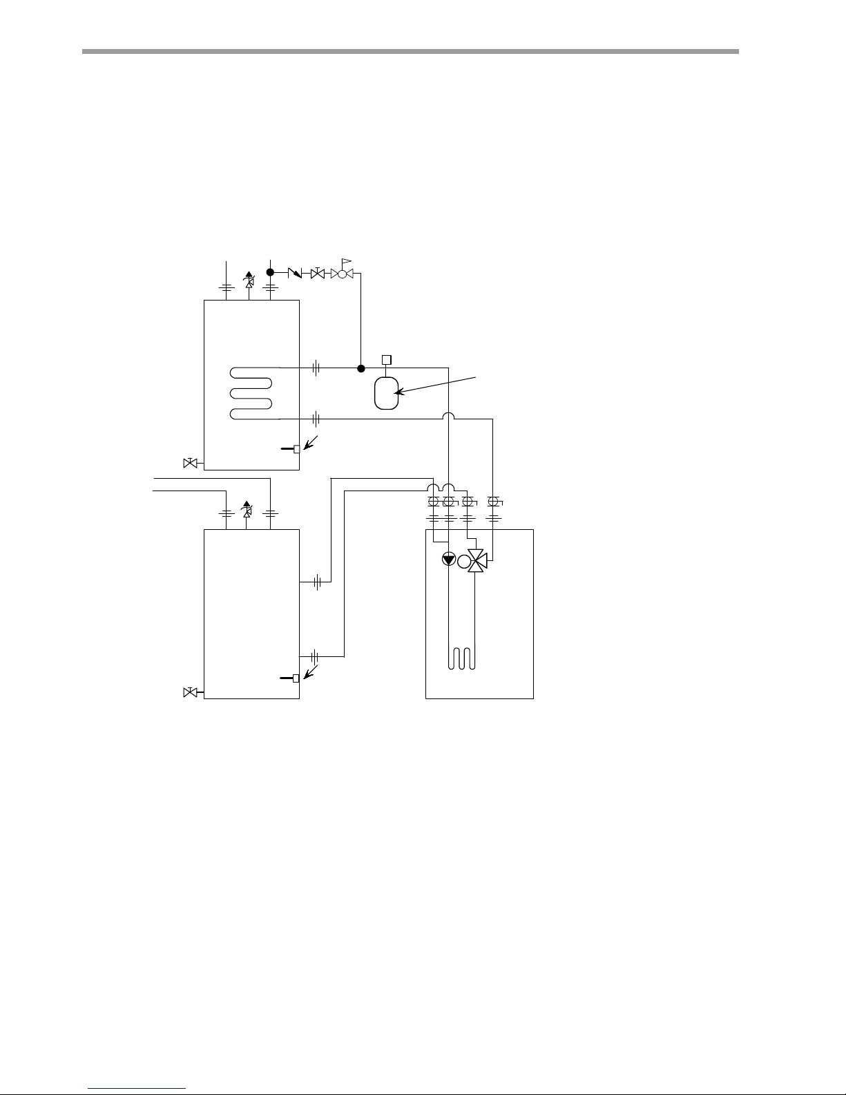
Load Piping Connections
Load piping connections are designated ‘Load Water In
and Out’ for the radiant heating system piping, and ‘DHW
Water In and Out’ (optional) for connection to the domestic
hot water piping. Any unused piping connections on the
load side of the THW unit will allow spillage of the load
circuit fl uid, as the radiant and DHW circuits are connected
internally.
If a unit is ordered with the DHW option and is not being
connected to a radiant heating system, the ‘Load Water
In and Out’ (radiant heating circuit) connections must be
connected to the ‘DHW In and Out’ piping using tees as
shown in Figure 1a. Failure to do so will lead to nuisance
high-pressure faults.
THW Unit Load Plumbing
Figure 1a: THW DHW Only Piping
CLIMATEMASTER WATER-SOURCE HEAT PUMPS
8
ClimateMaster Water-Source Heat Pumps
Tranquility® Water-to-Water THW Series
Revised: 02 January, 2013
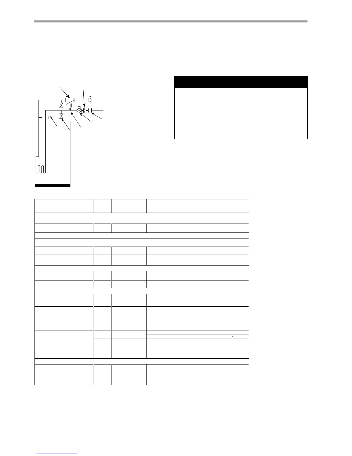
Load Plumbing Installation
,QGLUHFW
:DWHU+HDWHU
+HDWLQJ
%XIIHU7DQN
127(6
3ODFHDLUYHQWDWWKHKLJKHVWSRLQWLQWKHV\VWHP
7KHUPLVWRUVVKRXOGEHLQVWDOOHGLQDQLPPHUVLRQZHOO
/RFDWHWKHUPLVWRULQWKHERWWRPKDOIRIWKHWDQN
37SUHVVXUHWHPSHUDWXUHSRUWVDUHLQWHUQDOIRU7+:
XQLWVRQORDGDQGVRXUFHFRQQHFWLRQV
2WKHUFRPSRQHQWVDGGLWLRQDOEDOOYDOYHVXQLRQVHWF
PD\EHUHTXLUHGIRUHDVHRIVHUYLFH7KLVGUDZLQJ
VKRZVRQO\PLQLPXPUHTXLUHPHQWV<RXUVSHFLILF
LQVWDOODWLRQZLOOGLFWDWHILQDOFRPSRQHQWVHOHFWLRQV
%XIIHUWDQNPXVWEHDSSURYHGDVDKHDWLQJYHVVHO
/RFDOFRGHVXSHUFHGHVDQ\SLSLQJDUUDQJHPHQWVRU
FRPSRQHQWVVKRZQRQWKLVGUDZLQJ
7R)URP
5DGLDQW)ORRU
5DGLDWRU
%DVHERDUG
RU)DQ&RLO
+HDWLQJ6\VWHP
+&
+&
([S
7DQN
1RWH
$LU9HQW
7+:
8QLW
/RDG+;
EU]SOW
,1 287287
+7* '+:
0
'+:
,1
+7*
3 5 9
7KHUPLVWRU
1RWH
7KHUPLVWRU
1RWH
)RUV\VWHPVWKDWGRQRWLQFOXGH
RSWLRQDOIDFWRU\LQVWDOOHGH[SWDQN
Figure 1b: THW Typical Load Piping

THE SMART SOLUTION FOR ENERGY EFFICIENCY
9
climatemaster.com
Tranquility® Water-to-Water THW Series
Revised: 02 January, 2013
Typical open loop piping is shown in Figure 2. Shut off valves
should be included in case of servicing. Boiler drains or other
valves should be ‘tee’d’ into the line to allow acid fl ushing of
just the heat exchanger. Pressure temperature plugs should
be used so that fl ow and temperature can be measured.
Piping materials should be limited to PVC SCH80 or copper.
Due to the pressure and temperature extremes, PVC SCH40
is not recommended. Water quantity should be plentiful and
of good quality. Consult Table 2 for water quality guidelines.
The unit can be ordered with either a copper or cupro-nickel
water heat exchanger. Copper is recommended for closed
loop systems and open loop ground water systems that are
not high in mineral content or corrosiveness. In conditions
anticipating heavy scale formation or in brackish water, a
cupro-nickel heat exchanger is recommended. In ground
water situations where scaling could be heavy or where
biological growth such as iron bacteria will be present, a
closed loop system is recommended. Heat exchanger coils
may over time lose heat exchange capabilities due to a build
up of mineral deposits inside. These can be cleaned only by
a qualifi ed service mechanic as acid and special pumping
equipment are required.
Expansion Tank and Pump
Use a closed, bladder-type expansion tank to minimize mineral
formation due to air exposure. The expansion tank should be
sized to handle at least one minute run time of the pump to
prevent premature pump failure using its drawdown capacity
rating. The pump should be sized to the home’s domestic
water load 19-34 l/m plus the heat pump water load. Discharge
water from the unit is not contaminated in any manner and can
be disposed of in various ways depending on local building
codes; i.e. recharge well, storm sewer, drain fi eld, adjacent
stream or pond, etc. Most local codes forbid the use of
sanitary sewer for disposal. Consult your local building and
zoning department to assure compliance in your area.
Water Control Valve
Note the placement of the water control valve. Always
maintain water pressure in the heat exchanger by placing
water control valves at the outlet of the unit to prevent
mineral precipitation. Pilot operated or Taco slow closing
valve’s solenoid valves are recommended to reduce water
hammer. If water hammer persists, a mini-expansion tank can
be mounted on the piping to help absorb the excess hammer
shock. Insure that the total ‘VA’ draw of the valve can be
supplied by the unit transformer. For instance the Taco slow
closing valve can draw up to 35VA. This can overload smaller
40 or 50 VA transformers depending on the other controls
employed. A typical pilot operated solenoid valve draws
approximately 15VA. Note the special wiring diagram of the
AVM valve (Figure 9).
Flow Regulation
Flow regulation can be accomplished by two methods. First,
most water control valves have a built in fl ow adjustment.
By measuring the pressure drop through the unit heat
exchanger, fl ow rate can be determined and compared
to Table 8. Simply adjust the water control valve until the
desired fl ow is achieved. Secondly, a fl ow control device may
be installed. The devices are typically an orifi ce of plastic
material that is designed to allow a specifi ed fl ow rate. These
are mounted on the outlet of the water control valve. On
occasion, these valves can produce a velocity noise that
can be reduced by applying some back pressure. This is
accomplished by slightly closing the leaving isolation valve of
the well water setup.
Low Temperature Cutout
The water low temperature cutout setpoint should be
activated to avoid freeze damage to the unit. Consult the low
temperature cutout section of the controls description for
instructions.
CAUTION!
CAUTION! Refrigerant pressure activated water regulating
valves should never be used with this equipment.
Ground-Water Heat Pump Systems
CLIMATEMASTER WATER-SOURCE HEAT PUMPS
10
ClimateMaster Water-Source Heat Pumps
Tranquility® Water-to-Water THW Series
Revised: 02 January, 2013
Table 2: Water Quality Standards
Figure 2: Typical Open Loop/ Well Application
Water Quality
Parameter
HX
Material
Closed
Recirculating
Open Loop and Recirculating Well
Scaling Potential - Primary Measurement
pH/Calcium Hardness
All
pH < 7.5 and Ca Hardness <100ppm
Method
Index Limits for Probable Scaling Situations -
(Operation outside these limits is not recommended)
Ryznar
All
- 6.0 - 7.5
Stability Index If >7.5 minimize steel pipe use.
Langelier
All
-
-0.5 to +0.5
Saturation Index
If <-0.5 minimize steel pipe use. Based upon 66°C HWG and
Direct well, 29°C Indirect Well HX
Iron Fouling
Iron Fe2+(Ferrous)
All
-
<0.2 ppm (Ferrous)
(Bacterial Iron potential)
If Fe
2+
(ferrous)>0.2 ppm with pH 6 - 8, O2<5 ppm check for iron bacteria.
Iron Fouling
All
-
<0.5 ppm of Oxygen
Above this level deposition will occur .
Corrosion Prevention
pH
All
6 - 8.5
6 - 8.5
Monitor/treat as
needed
Minimize steel pipe below 7 and no open tanks with pH <8
Hydrogen Sulfide (H
2
S)
All
- <0.5 ppm
At H
2
S>0.2 ppm, avoid use of copper and copper nickel piping or HX's.
Rotten egg smell appears at 0.5 ppm level.
Copper alloy (bronze or brass) cast components are OK to <0.5 ppm.
Ammonia ion as hydroxide, chloride,
nitrate and sulfate compounds
All
-
<0.5 ppm
Maximum
Maximum Allowable at maximum water temperature.
Chloride Levels
10$C24$C38
C
Copper
Cupronickel
- <20ppm NR NR
- <150 ppm NR NR
304 S
S - <400 ppm <250 ppm <150 ppm
316 S
S - <1000 ppm <550 ppm < 375 ppm
Titanium - >1000 ppm >550 pp m >375 ppm
Erosion and Clogging
Particulate Size and
Erosion
All
<10 ppm of particles
and a maximum
velocity of 1.8 m/s
Filtered for maximum
841 micron [0.84 mm,
20 mesh] size.
<10 ppm (<1 ppm "sandfree” for reinjection) of particles and a maximum
velocity of 1.8 m/s. Filtered for maximum 841 micron 0.84 mm,
20 mesh] size. Any particulate that is not removed can potentially
clog components.
Notes:
Rev.: 3/22/2012
15Application not recommended.
1RGHVLJQ0D[LPXP
&ORVHG5HFLUFXODWLQJV\VWHPLVLGHQWLILHGE\D
closed pressurized piping system.
5HFLUFXODWLQJRSHQZHOOVVKRXOGREVHUYHWKHRSHQUHFLUFXODWLQJGHVLJQFRQVLGHUDWLRQV
Above the given limits, scaling is likely to occur. Scaling indexes should be calculated using the limits below
Scaling indexes should be calculated at 66°C for direct use and HWG applications, and at 32°C for indirect HX use.
A monitoring plan should be implemented.
The ClimateMaster Water Quality Table provides water quality requirements for ClimateMaster coaxial heat exchangers. When water properties are outside of those
requirements, an external secondary heat exchanger must be used to isolate the heat pump heat exchanger from the unsuitable water. Failure to do so will void the
warranty for the coaxial heat exchanger.
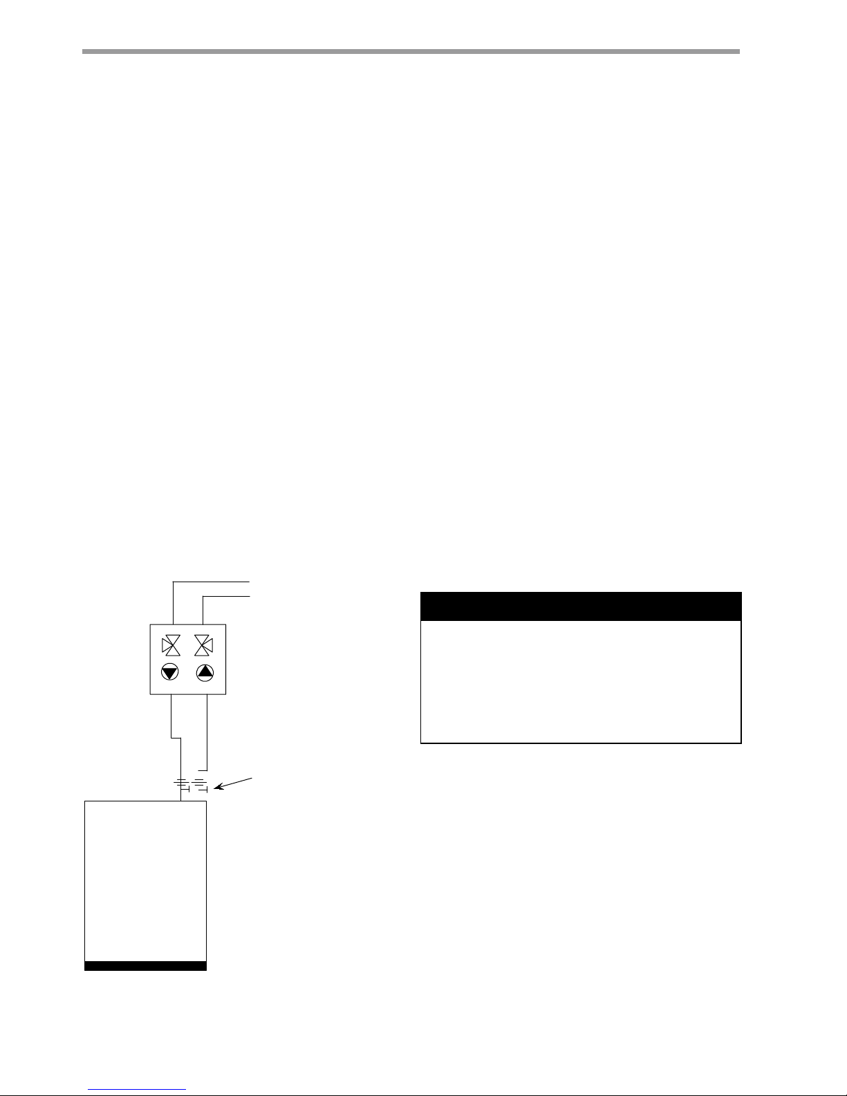
THW
NOTES:
1. P/T (pressure/temperature) ports are internal for THW
series units.
2. Other components (additional ball valves, unions, etc.)
may be required for ease of service. This drawing
shows only minimum requirements. Your specific
installation will dictate final component selections.
3. Local code supercedes any piping arrangements or
components shown on this drawing.
Sound absorbing pad
Source HX
(coaxial)
IN OUT
P/T port
To proper discharge location
S
From pressure tank
Strainer (optional)
Shut-off valve
Boiler drain (for flushing)
Water control valve
High Pressure Switch
Flow regulator
Ground-Water Heat Pump Systems
WARNING! Polyolester Oil, commonly known as POE
oil, is a synthetic oil used in many refrigeration systems
including those with HFC-410A refrigerant. POE oil, if it
ever comes in contact with PVC or CPVS piping, may
cause failure of the PVC/CPVC. PVC/CPVC piping should
never be used as supply or return water piping with water
source heat pump products containing HFC-410A as
system failures and property damage may result.
WARNING!

THE SMART SOLUTION FOR ENERGY EFFICIENCY
11
climatemaster.com
Tranquility® Water-to-Water THW Series
Revised: 02 January, 2013
Piping Installation
The typical closed loop ground source system is shown in
Figure 3. All earth loop piping materials should be limited
to only polyethylene fusion in inground sections of the
loop. Galvanized or steel fi tting should not be used at any
time due to their tendency to corrode. All plastic to metal
threaded fi ttings should be avoided due to their potential
to leak in earth coupled applications and a fl anged fi tting
substituted. P/T plugs should be used so that fl ow can
be measured using the pressure drop of the unit heat
exchanger in lieu of other fl ow measurement means.
Earth loop temperatures can range between -3.9 - 43.3°C.
Upon completion of the ground loop piping, pressure
test the loop to assure a leak free system. Horizontal
Systems: test individual loops as installed. Test entire
system when all loops are assembled.
Vertical U-Bends and Pond Loop Systems: test vertical
U-bends and pond loop assemblies prior to installation
with a hydrostatic test pressure of at least 689 kPa.
Flushing the Earth Loop
Once piping is completed between the unit, fl ow
center and the ground loop (Figure 3), fi nal purging
and charging of the loop is needed. A fl ush cart (at
least a 1.1 kW pump) is needed to achieve adequate
fl ow velocity in the loop to purge air and dirt particles
from the loop itself. An antifreeze solution is used in
most areas to prevent freezing. All air and debris must
be removed from the earth loop piping system before
operation. Flush the loop with a high volume of water
at a high velocity (0.6 m/s in all piping) both directions.
The steps below must be followed for proper fl ushing.
Fill loop with water from a garden hose through fl ush
cart before using fl ush cart pump to ensure an even
fi ll. Once full, do not allow the water level in the fl ush
cart tank to drop below the pump inlet line or air can
be pumped back out to the earth loop. Try to maintain
a fl uid level in the tank above the return tee so that
air can not be continuously mixed back into the fl uid.
345 kPa surges can be used to help purge air pockets
by simply shutting off the return valve going into the
fl ush cart reservoir. This ‘dead heads’ the pump to 345
kPa. To dead head the pump until maximum pumping
pressure is reached, open the valve back up and a
pressure surge will be sent through the loop to help
purge air pockets from the piping system. Notice the
drop in fl uid level in the fl ush cart tank. If air is purged
from the system, the level will drop only 25-50mm
in a 254mm diameter PVC fl ush tank since liquids
are incompressible. If the level drops more than
this, fl ushing should continue since air is still being
compressed in the loop fl uid. Do this a number of
times.
When the fl uid level drops less than 25-50mm in a
254mm diameter tank the fl ow can be reversed. Finally
the dead head test should be checked again for an
indication of air in the loop. This fl uid level drop is
your only indication of air in the loop.
Table 3: Approximate Fluid Volume
Table 4: Antifreeze Percentages by Volume
Type
Minimum Temperature for Low Temperature Protection
-12.2°C -9.4°C -6.7°C -3.9°C
Methanol
100% USP food grade Propylene Glycol
Ethanol*
25%
38%
29%
21%
25%
25%
16%
22%
20%
10%
15%
14%
* Must not be denatured with any petroleum based product
Fluid Volume (liters per 30 meters Pipe)
Pipe Size Volume (liters)
Copper
1” 15.3
1.25” 23.8
2.5” 34.3
Rubber Hose 1” 14.6
Polyethylene
3/4” IPS SDR11 10.4
1” iPS SDR11 16.7
1.25” IPS SDR11 29.8
1.5” IPS SDR11 40.7
2” IPS SDR11 67.0
1.25” IPS SCH40 30.9
1.5” IPS SCH40 40.7
2” IPS SCH40 63.4
Unit Heat Exchanger Typical 3.8
Flush Cart Tank [254mm x 91.4cm tall] 37.9
Ground-Loop Heat Pump Applications
CLIMATEMASTER WATER-SOURCE HEAT PUMPS
12
ClimateMaster Water-Source Heat Pumps
Tranquility® Water-to-Water THW Series
Revised: 02 January, 2013
Figure 3: Typical Earth Loop Connection.
Antifreeze may be added before, during, or after the
fl ushing procedure. However, depending upon which
time is chosen, antifreeze could be wasted when
emptying the fl ush cart tank. See antifreeze section
for more details. Loop static pressure will fl uctuate
with the seasons. Pressures will be higher in the winter
months than during the cooling season. This fl uctuation
is normal and should be considered when charging
the system initially. Run the unit in either heating or
cooling for a number of minutes to condition the loop
to a homogenous temperature. This is a good time for
tool cleanup, piping insulation etc. Then fi nal fl ush and
pressurize the loop to a static pressure of 275-345 kPa
(winter) 100-138 kPa (summer).
After pressurization, be sure to remove the plug in
the end of the Grundfos loop pump motor(s) to allow
trapped air to be discharged and to insure the motor
housing has been fl ooded. This is not required for
Taco circulators. Insure the loop fl ow center provides
adequate fl ow through the unit by checking pressure
drop across the heat exchanger and comparing it to
the fi gures shown in Table 8.
Antifreeze
In areas where minimum entering loop temperatures
drop below 4.4°C or where piping will be routed
through areas subject to freezing, antifreeze is needed.
Alcohols and glycols are commonly used as antifreezes,
however your local territory manager should be
consulted for the antifreeze best suited to your area.
Freeze protection should be maintained to -9.4°C
below the lowest expected entering loop temperature.
All alcohols should be premixed and pumped from
a reservoir outside of the building when possible
or introduced under water level to prevent fuming.
Initially calculate the total volume of fl uid in the piping
system using Table 3. Then use the percentage by
volume shown in Table 4 for the amount of antifreeze.
Antifreeze concentration should be checked from a
well mixed sample using a hydrometer to measure
specifi c gravity.
Low Water Temperature Cut-Out Setting
When an antifreeze is selected the low temperature
limit setpoint should be switched to the lower
setting to avoid nuisance faults. Consult Low Water
Temperature Cut-Out Setting in the controls section for
more information.
7R)URP*URXQG/RRS
7+:
,1 287
127(6
37SUHVVXUHWHPSHUDWXUHSRUWVDUHLQWHUQDOIRU7+:
VHULHVXQLWV
6RXUFHZDWHUSLSLQJPXVWEHLQVXODWHGIRUFORVHGORRS
LQVWDOODWLRQV
2WKHUFRPSRQHQWVDGGLWLRQDOEDOOYDOYHVXQLRQVHWF
PD\EHUHTXLUHGIRUHDVHRIVHUYLFH7KLVGUDZLQJ
VKRZVRQO\PLQLPXPUHTXLUHPHQWV<RXUVSHFLILF
LQVWDOODWLRQZLOOGLFWDWHILQDOFRPSRQHQWVHOHFWLRQV
/RFDOFRGHVXSHUFHGHVDQ\SLSLQJDUUDQJHPHQWVRU
FRPSRQHQWVVKRZQRQWKLVGUDZLQJ
)ORZ&RQWUROOHU
37SRUW
6RXQGDEVRUELQJSDG
2SWLRQDO)ORZ&RQWUROOHU
IRUXQLWVQRWHTXLSSHG
ZLWKDQLQWHUQDOSXPS
Ground-Loop Heat Pump Applications
WARNING! Polyolester Oil, commonly known as POE
oil, is a synthetic oil used in many refrigeration systems
including those with HFC-410A refrigerant. POE oil, if it
ever comes in contact with PVC or CPVS piping, may
cause failure of the PVC/CPVC. PVC/CPVC piping should
never be used as supply or return water piping with water
source heat pump products containing HFC-410A as
system failures and property damage may result.
WARNING!
 Loading...