

Page 1
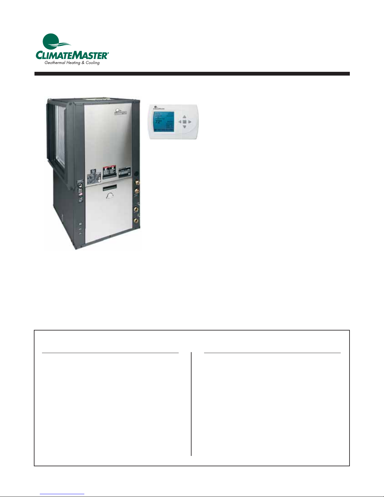
Tranquility® Digital
Quick Start Guide
97B0107N01
Residential Packaged and Split
DIGITAL Geothermal Heat Pumps
With iGate™ and vFlow™ Technology
Rev.: January 25, 2016
Step Title Page
1 Thermostat Confi guration 3
Staging 3
Auxiliary Heat 3
Programming 3
2 System Confi guration 4
Airfl ow Selection 4
Option Selection 4
Unit Confi guration 4
Pump Confi guration 5
Valve Confi guration 5
3 Accessory Confi guration 5
Air Filter 6
Humidifi er 6
UV Lamp 6
Air Cleaner 6
Table of Contents
Step Title Page
4 Input Dealer Information 6
5 Humidity Confi guration 6
6 Temperature Algorithm 6
7 Demand Reduction Confi guration 7
8 Unit and System 8
Pre-Start Checklist
9 Unit Start-up Procedure 8
Page 2

This page was intentionally left blank.
Page 3

Tranquility® Digital Quick Start Guide
Rev.: January 25, 2016
ClimateMaster Digital units are shipped from the factory
with default values for key parameters such as air fl ow and
water fl ow settings. The unit will operate with these default
settings, however, the installer may wish to customize these
settings to better match installation conditions. This guide
will walk the installer through those settings. More detail is
available in the unit IOM.
The fi rst step is to enter the Installer Menu. The fi rst time the
unit is powered up the ATC series thermostat display will take
you to the Installer’s Menu. Or you can enter the Installer’s
Menu anytime by placing the thermostat/system in the “OFF”
mode, then holding the “UP” and “DOWN” arrow keys simultaneously for 5 seconds. Once in the Installer’s Menu the
following menus will appear.
Step 1 Thermostat Confi guration
Upon initial power up, the communicating thermostat will
prompt the installer for the thermostat confi guration settings.
The software version of the thermostat and DXM2 board it
is connected to, are displayed on the thermostat Installer
Screen. If the DXM2 version is not displayed, the ATC thermostat is of an earlier version.
2.0 Installer Menu Settings
2.1 INSTALLER MENU SETTINGS ACCESS
The Installer Settings can be accessed at any time from the
Main Operating screen by holding the up/down arrows simultaneously for 5 seconds while the thermostat is in OFF Mode.
2.2 THERMOSTAT CONFIGURATION
Upon initial power up, the communicating thermostat will
prompt the installer for the thermostat confi guration settings.
Model number and software version of thermostat and
software version of connected DXM2 are also displayed on
this screen.
AUXILIARY HEAT
Adjust the Auxiliary Heat options using the up/down arrow
buttons. Press the center button to save changes.
• Electric (default) – for control of a system with
electric auxiliary heat
• Multi-Fuel – for control of a system with furnace
for auxiliary heat
• No Auxiliary Heat – for control of a system with
no auxiliary heat
THERMOSTAT
CONFIGURATION
ELECTRIC
MULTI FUEL
NO AUXILIARY HEAT
SELECT OPTION
PREVIOUS SAVE
PROGRAMMING
Adjust the Programming options using the up/down arrow
buttons. Press the center button to save changes.
• Programmable (default) – enables 7-day
programming
• Non-Programmable – disables 7-day programming
• Night Setback – enables night setback
programming
NOTE: When the thermostat is confi gured for
nonprogrammable mode, the Display Date and Time setting
defaults to NO.
THERMOSTAT
CONFIGURATION
PROGRAMMABLE
2.2.1 STAGING
Adjust the staging option using the up/down arrow buttons.
Press the center button to save changes.
• Single Stage – for control of a single stage
compressor applications
• Multi-Stage (default) – for control of multi-
stage compressor applications
THERMOSTAT
CONFIGURATION
SINGLE STAGE
MULTI STAGE
SELECT OPTION
PREVIOUS SAVE
NON PROGRAMMABLE
NIGHT SETBACK
SELECT OPTION
PREVIOUS SAVE
3
Page 4
Tranquility® Digital Quick Start Guide
Rev.:January 25, 2016
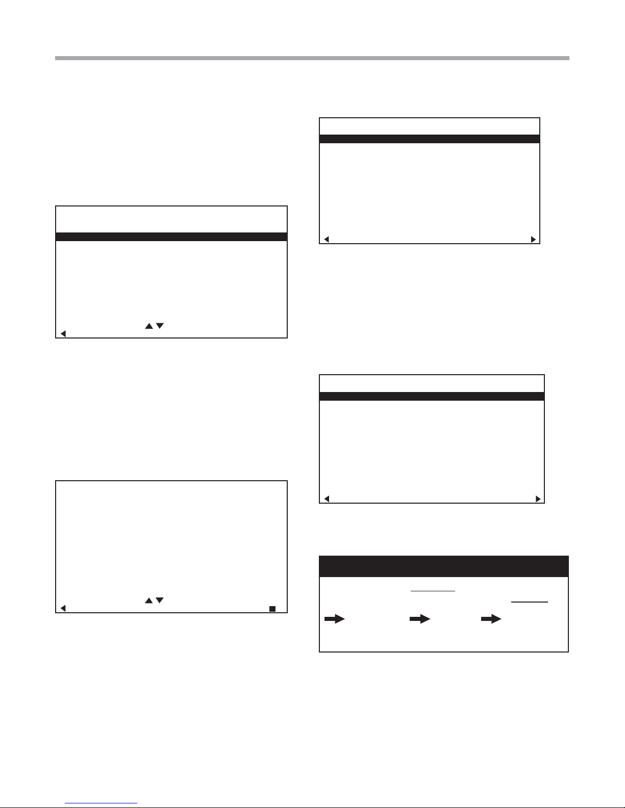
Step 2 System Confi guration
Use System Confi guration to adjust critical equipment set-
tings. The System Confi guration information will be auto-
matically obtained from each communicating control in the
system.
INSTALLER SETTINGS
THERMOSTAT CONFIG
SYSTEM CONFIG
ACCESSORY CONFIG
INPUT DEALER INFO
HUMIDITY CONFIG
TEMPERA TURE ALGORITHM
DEMAND REDUCTION CNFG
SERVICE MODE
RESTORY DEFAULTS
ATC32U01
SELECT OPTION
PREVIOUS
Note 1: The Air fl ow Selection menu will not be present if the
connected communicating control is confi gured for No blower.
Note 2: The Pump Confi guration menu will not be present
if the connected communicating control is confi gured for
OTHER.
CFM
AIRFLOW SELECTION
HEAT STAGE 1 600
HEAT STAGE 2 750
AUXILIARY HEAT 850
EMERGENCY HEAT 850
COOL STAGE 1 525
COOL STAGE 2 700
COOL DEHUMID 1 425
COOL DEHUMID 2 550
CONTINUOUS FAN 350
HEAT OFF DELAY 60
COOL OFF DELAY 30
PREVIOUS NEXT
OPTION SELECTION
Adjust the Option settings using the up/down arrow buttons.
Press the center button to select each item.
• Motorized Valve (defaults stored in control) –
valid range: Off, On
• Compressor ACSD (default stored in control) –
valid range: 5 to 8 (in 1 minute increments)
NOTE: The Compressor Anti-Short Cycle Delay setting
provides equipment protection by forcing the compressor to
wait a few minutes before restarting.
OPTION SELECTION
MOTORIZED VALVE OFF
Note 3: The Valve Confi guration menu will not be present
if the connected communicating control is confi gured for
OTHER.
SYSTEM CONFIGURATION
AIRFLOW SELECTION
OPTION SELECTION
UNIT CONFIG TE026
PUMP CONFIGURATION
SELECT OPTION
PREVIOUS SAVE
AIRFLOW SELECTION
Adjust the airfl ow settings for each system operating mode
using the up/down arrow buttons. Press the center button to
select each item.
• Airfl ow Settings (default stored in control) –
valid range: obtained from control (in 25 CFM
increments)
• Blower Off Delay (default 60 seconds) – valid
range: 0 to 255 seconds (in 5 second increments)
NOTE: The Airfl ow Settings will only be present if the
connected communicating control is confi gured for ECM
blower.
4
COMPRESSOR ASCD 5
PREVIOUS NEXT
UNIT CONFIGURATION
The controller should be confi gured from the factory for
its unit model. However, it is a good idea to review the
confi guration to ensure it is correctly confi gured.
NOTICE: If installing MULTIPLE vFlow™ Internal VS
Flow Controller units (in parallel) on one loop, ALWAYS
select ‘VS PUMP PARALLEL’ under Installer Settings
System Confi g Unit Confi g Loop Confi g.
Also, follow proper pump selection procedures for parallel
pumping applications.
Adjust the Unit Confi guration settings including Heat
Pump Family, Heat Pump Size, Blower Type, and Loop
Confi guration using the up/down arrow buttons. Press the
center button to select each item.
• Heat Pump Family (default stored in control) –
valid range: TE, TZ, TES, TEP, TAH
• Heat Pump Size (default stored in control) –
valid range: depends on Heat Pump Family setting
• Blower Type (default stored in control) – valid
range: NONE, PSC–2SPD, ECM, PSC–1SPD
Geothermal Heat Pump Systems
• Loop Confi g (default stored in control) – valid
NOTICE!
Page 5
Tranquility® Digital Quick Start Guide
Rev.: January 25, 2016
range: Other, VS PUMP SINGLE, VS PUMP
PARALLEL, MOD VALVE, MOD VALVE MIN POS
THERMOSTAT
CONFIGURATION
SINGLE STAGE
MULTI STAGE
SELECT OPTION
PREVIOUS SAVE
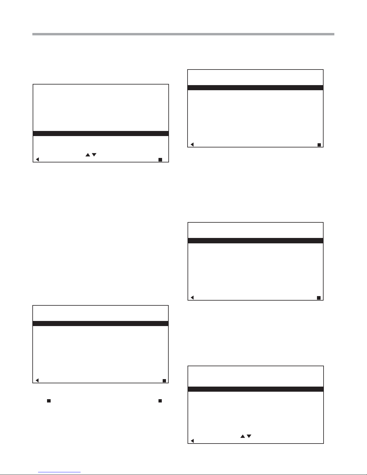
vFlow™ PUMP CONFIGURATION
vFlow™ VS internal flow control pump can be controlled
either through temperature differential (Delta T) or can be set
to specific speed (fixed; % of full speed for each heat and
cool stage).
Confi gure temperature differentials at the thermostat for
vFlow™ units with an internal fl ow control pump.
Adjust the Pump Confi guration settings using the up/down
arrow buttons. Press the center button to select each item.
• Heating Delta T (default stored in control) –
valid range: 4 to 12ºF (in 1ºF increments)
• Cooling Delta T (default stored in control) –
valid range: 9 to 20ºF (in 1ºF increments)
VARIABLE SPD INTERNAL
PUMP CONFIGURATION
LOOP OPTION SINGLE
PUMP CONTROL FIXED
HEATING STAGE 1 60%
COOLING STAGE 2 75%
COOLING STAGE 1 50%
COOLING STAGE 2 70%
PREVIOUS SELECT
If Pump Confi guration is set to ‘VS PUMP PARALLEL’, valid
range changes to 50-90% (in 1% increments).
vFlow™ VALVE CONFIGURATION
Adjust the Valve Confi guration settings using the up/down
arrow buttons. Press the center button to select each item.
• Heating Delta T (default stored in control) –
valid range: 4 to 12ºF (in 1ºF increments)
• Cooling Delta T (default stored in control) –
valid range: 9 to 20ºF (in 1ºF increments)
MODULATING VALVE
CONFIGURATION
DEG
HEATING DELTA T 8
COOLING DELTA T 15
Maximum Heat LWT (valid range based on specifi c model;
refer to model IOM). Minimum Cool LWT (valid range based
on specifi c model; refer to model IOM).
VARIABLE SPD INTERNAL
PUMP CONFIGURATION
LOOP OPTION PARALLEL
PUMP CONTROL DELTA T
HEATING DELTA T 7 F
COOLING DELTA T 10 F
MAXIMUM HEAT LWT 80 F
MINIMUM COOL LWT 40 F
PREVIOUS SELECT
To control vs pump by fi xed speed, select ‘Pump Control’,
press
save.
Default stored in control. Valid range: 15% - 90% (in 1%
increments)
, use down arrow to select ‘Fixed’, and press to
PREVIOUS NEXT
Step 3 Accessory Confi guration
The ATC32 series thermostat can be confi gured to provide
reminders to users when certain system maintenance is
needed. A service message will fl ash at the top of the Main
screen when a service timer expires to alert the user that it is
time to service accessory options.
INSTALLER SETTINGS
THERMOSTAT CONFIG
SYSTEM CONFIG
ACCESSORY CONFIG
INPUT DEALER INFO
HUMIDITY CONFIG
TEMPERA TURE ALGORITHM
DEMAND REDUCTION CNFG
SERVICE MODE
RESTORY DEFAULTS
ATC32U01
SELECT OPTION
PREVIOUS
5
Page 6

Tranquility® Digital Quick Start Guide
Rev.:January 25, 2016
AIR FILTER
This feature displays an alert to remind the user to change
the air fi lter after the selected time has passed. Adjust the
Air Filter Reminder settings using the up/down arrow buttons.
Press the center button to save changes.
• Cumulative Run Time (default Off) – valid range:
Off, 400 to 3600 hours (in 100 hour increments)
• Calendar Time (default Off) – valid range: Off, 3
to 48 months (in 3 month increments)
HUMIDIFIER
This feature displays an alert to remind the user to change
the humidifi er pad after the selected time has passed.
Adjust the Humidifi er Reminder settings using the up/down
arrow buttons. Press the center button to save changes.
• Cumulative Run Time (default Off) – valid range:
Off, 400 to 3600 hours (in 100 hour increments)
• Calendar Time (default Off) – valid range: Off, 3
to 24 months (in 3 month increments)
UV LAMP
This feature displays an alert to remind the user to change
the UV lamps after the selected time has passed.
Adjust the UV Lamp Reminder settings using the up/down
arrow buttons. Press the center button to save changes.
• Cumulative Run Time (default Off) – valid range:
Off, 400 to 3600 hours (in 100 hour increments)
• Calendar Time (default Off) – valid range: Off, 3
to 48 months (in 3 month increments)
AIR CLEANER
This feature displays an alert to remind the user to clean the
fi lter(s) after the selected time has passed.
Adjust the Air Cleaner Reminder settings using the up/down
arrow buttons. Press the center button to save changes.
• Cumulative Run Time (default Off) – valid range:
Off, 400 to 3600 hours (in 100 hour increments)
• Calendar Time (default Off) – valid range: Off, 3
to 24 months (in 3 month increments)
Step 4 Input Dealer Information
Enter/edit the Dealer Information settings, including Brand,
Name, Model Number, Serial Number, Contractor Name, and
Contractor Phone number, using the up/down arrow buttons.
Press the center button to save changes.
Step 5 Humidity Confi guration
Confi gure humidity control settings (dehumidifi cation/ humidi-
fi cation).
• Dehumidifi cation – This logic will communicate
a Dehumidifi cation output when the humidity is
greater than the setpoint (acts as a dehumidistat).
The Dehumidifi cation output will not be
communicated when the humidity is below the
setpoint.
• Humidifi cation – This logic will communicate a
Humidifi cation output when the humidity is less
than the setpoint (acts as a humidistat). When the
Humidifi cation output is active, the fan output will
also be active. The Humidifi cation output will not
be communicated when the humidity is above the
setpoint.
• Both – Incorporates both Dehumidifi cation and
Humidifi cation logic.
• None (default) – Dehumidifi cation and
Humidifi cation outputs will not be communicated.
Step 6 Temperature Algorithm
Confi gure the logic the thermostat uses to meet the tempera-
ture setpoints.
• Proportional Integral (default) – This logic will
use a combination of temperature differential and
operating time to determine the appropriate heating
or cooling stages for operation (see NOTE 1).
• Proportional Integral (No Down Staging) – This
logic includes the Proportional Integral logic, but
in addition the logic keeps all active heating or
cooling stages energized until the demand is fully
satisfi ed (see NOTE 1).
• Differential – This logic will only use temperature
differential to determine the appropriate heating or
cooling stages for operation. This logic will keep all
active heating or cooling stages energized until the
demand is fully satisfi ed (see NOTE 2).
NOTE 1: The Proportional Integral options require fi rst stage
heating or cooling to be active for a minimum of 5 minutes,
before energizing second stage when confi gured for multi
stage operation.
NOTE 2: The Differential option will activate fi rst stage
heating or cooling when the temperature is more than the
fi rst stage differential value (UM section 5.6.2.3), below or
above the setpoint. Second stage heating or cooling will be
activated when the temperature is more than the fi rst and
second stage differential values combined, below or above
the setpoint. Third stage heating will be activated when the
temperature is more than the fi rst, second, and third stage
differential values combined (UM section 5.6.2.3), below the
setpoint.
Adjust the Humidity Control settings using the up/down arrow
buttons. Press the center button to save changes.
6
Geothermal Heat Pump Systems
Page 7
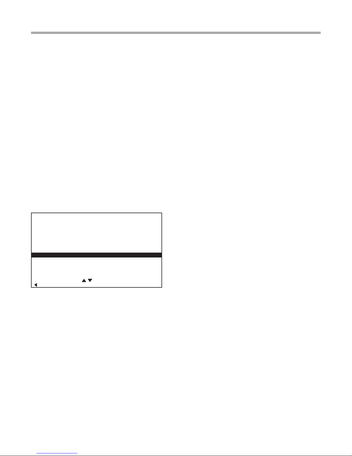
Step 7 Demand Reduction
Confi guration
Users may wish to take advantage of the Demand Reduction
feature where utility companies offer special rates for demand
reduction, or simply to save energy during certain time
periods. Demand Reduction is activated by an input signal at
the unit control board to reduce the electric load while peak
utility rates are high. The Demand Reduction Confi guration
mode selects which of the available unit control inputs is to
be used as the activation signal. While a physical input signal
is present at the selected input, the thermostat will implement
load reduction by limiting operation or capacity.
Adjust the Demand Reduction Confi guration setting using
the up/down arrow buttons. Press the center button to save
changes.
• No Demand Reduction (default) – Demand
Reduction operating mode will not be activated by
a DXM2/CXM2 input.
• DXM2 Inputs – Assigns a DXM2 input to activate
Demand Reduction operating mode.
Tranquility® Digital Quick Start Guide
Rev.: January 25, 2016
INSTALLER SETTINGS
THERMOSTAT CONFIG
SYSTEM CONFIG
ACCESSORY CONFIG
INPUT DEALER INFO
HUMIDITY CONFIG
TEMPERA TURE ALGORITHM
DEMAND REDUCTION CNFG
SERVICE MODE
RESTORY DEFAULTS
ATC32U01
SELECT OPTION
PREVIOUS
7
Page 8

Tranquility® Digital Quick Start Guide
Rev.:January 25, 2016
Start-Up Guide
Step 8 Unit and System Pre-Start
Check List
BEFORE POWERING SYSTEM, please check the following:
UNIT CHECKOUT
Shutoff valves: Insure that all isolation valves are open.
Line voltage and wiring: Verify that voltage is within
an acceptable range for the unit and wiring and fuses/
breakers are properly sized. Verify that low voltage wiring
is complete.
Unit control transformer: Insure that transformer has the
properly selected voltage tap. Residential 208-230V units
are factory wired for 230V operation unless specifi ed
otherwise.
Loop/water piping is complete and purged of air. Water/
piping is clean.
Antifreeze has been added if necessary.
Entering water and air: Insure that entering water and air
temperatures are within operating limits.
Low water temperature cutout: Verify that low water
temperature cut-out on the DXM2 control is properly set.
(Only cut JW3 if you have anti-freeze protection to15°F
(-9°C) in the loop)
Unit fan: Manually rotate fan to verify free rotation and
insure that blower wheel is secured to the motor shaft.
Be sure to remove any shipping supports if needed.
DO NOT oil motors upon start-up. Fan motors are
permanently lubricated.
Condensate line: Verify that condensate trap is properly
installed and pitched.
Verify that HWG pump is turned off unless piping is
completed and air has been purged from the system. (S3
dipswitch #4)
Unit air coil and fi lters: Insure that fi lter is clean and
accessible. Clean air coil of all manufacturing oils.
Unit controls: Verify that DXM2 fi eld selection options are
properly set and that low voltage wiring is complete.
Desired Blower CFM and Water ∆T is set via
communicating thermostats or diagnostic tool.
Service/access panels are in place.
SYSTEM CHECKOUT
System water temperature: Check water temperature for
proper range.
System pH: Check and adjust water pH if necessary to
maintain a level between 6 and 8.5. Proper pH promotes
longevity of hoses and fi ttings (see Water Quality Table in
unit IOM).
System fl ushing: Verify that all air is purged from the
system. Air in the system can cause poor operation or
system corrosion. Water used in the system must be
potable quality initially and clean of dirt, piping slag,
and strong chemical cleaning agents. Some antifreeze
solutions may require distilled water.
Internal Flow Controller: Verify that it is purged of air and
in operating condition.
Low water temperature cutout: Verify that low water
temperature cut-out controls are set properly (LT1 JW3).
Miscellaneous: Note any questionable aspects of the
installation.
CAUTION!
CAUTION! Verify that ALL water valves are open and
allow water fl ow prior to engaging the compressor.
Freezing of the coax or water lines can permanently
damage the heat pump.
CAUTION!
CAUTION! To avoid equipment damage, DO NOT
leave system fi lled in a building without heat during the
winter unless antifreeze is added to the water loop. Heat
exchangers never fully drain by themselves and will
freeze unless winterized with antifreeze.
Step 9 Unit Start-up Procedure
Unit Start-up Procedure
1. Turn the thermostat fan position to “ON.” Blower should
start.
2. Turn Blower off .
3. Ensure all valves are adjusted to their full open position.
Ensure line power to the heat pump is on.
4. Room temperature should be within the minimummaximum ranges of listed in the unit IOM. During startup checks, loop water temperature entering the heat
pump should be between 30°F [-1°C] and 95°F [35°C].
5. It is recommended that water-to-air units be fi rst started
in the cooling mode, when possible. This will allow liquid
refrigerant to fl ow through the fi lter-drier before entering
the TXV, allowing the fi lter-drier to catch any debris that
might be in the system before it reaches the TXV.
6. Two factors determine the operating limits of geothermal
heat pumps, (a) return air temperature, and (b) entering
water temperature. When either of the factors is at a
minimum or maximum level, the other factor must be at
normal levels to insure proper unit operation.
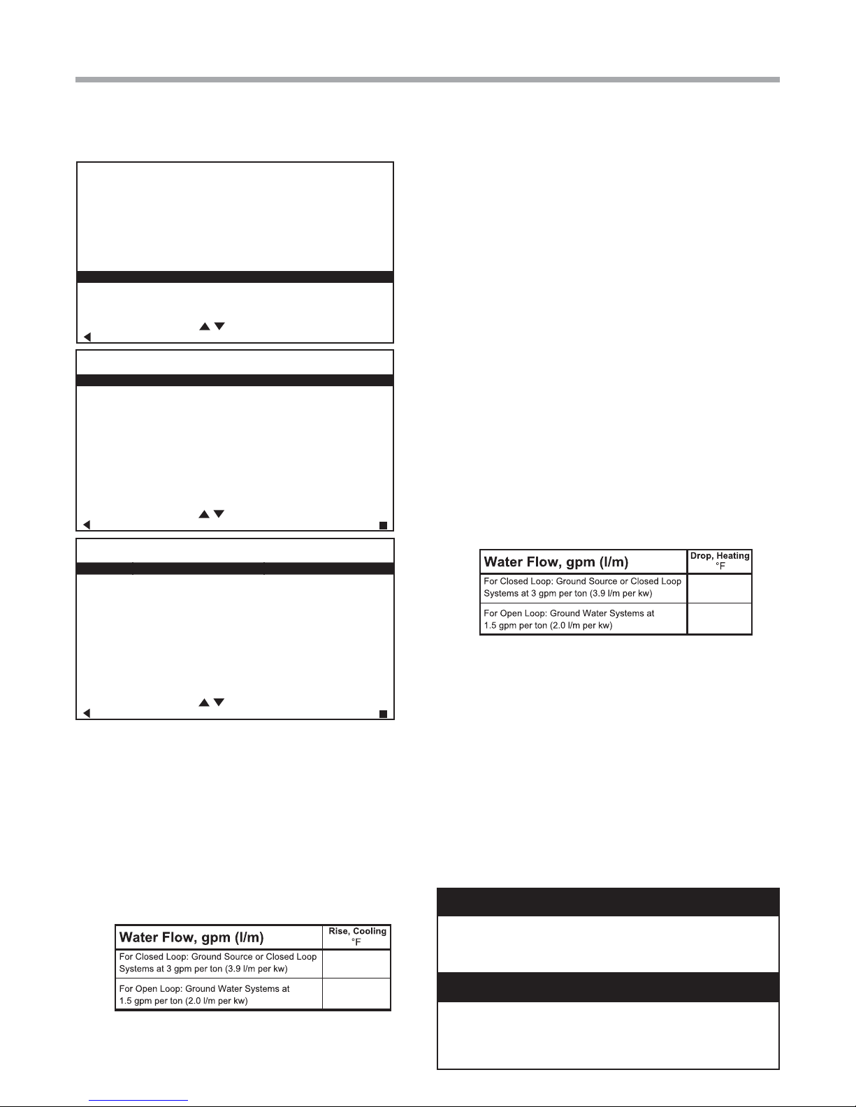
a. Place the unit in Manual Operation. When in manual
mode activate Y1,Y2, and O to initiate the cooling
mode. Also manually increase CFM until desired
cooling CFM is achieved. Next adjust pump speed
% until desired loop temperature diff erence (leaving
water temperature minus entering water temperature)
is achieved. (For modulating valve adjust valve %).
8
Geothermal Heat Pump Systems
Page 9
Tranquility® Digital Quick Start Guide
9 - 12
20 - 26
4 - 8
10 - 17
Rev.: January 25, 2016
INSTALLER SETTINGS
THERMOSTAT CONFIG
SYSTEM CONFIG
ACCESSORY CONFIG
INPUT DEALER INFO
HUMIDITY CONFIG
TEMPERA TURE ALGORITHM
DEMAND REDUCTION CNFG
SERVICE MODE
RESTORY DEFAULTS
ATC32U01
SELECT OPTION
PREVIOUS
SERVICE MODE
MANUAL OPERATION
CONTROL DIAGNOSTICS
DIPSWITCH CONFIG
FAULT HISTORY
CLEAR FAULT HISTORY
SELECT OPTION
PREVIOUS SELECT
MANUAL OPERATING MODE
Y1 COMM OUTPUT OFF
Y2 COMM OUTPUT OFF
W COMM OUTPUT OFF
O COMM OUTPUT OFF
G COMM OUTPUT OFF
H COMM OUTPUT OFF
DH COMM OUTPUT OFF
ECM AIRFLOW 0
PUMP SPEED 0%
TEST MODE OFF
SELECT OPTION
PREVIOUS SELECT
b. Check for cool air delivery at the unit grille within a
few minutes after the unit has begun to operate.
NOTE: Units have a fi ve minute time delay in the control
circuit that can be bypassed on the DXM2 control board
by placing the unit in the “Test” mode as shown in the unit
IOM. Check for normal air temperature drop of 15°F to 25°F
(cooling mode).
c. Verify that the compressor is on and that the water
temperature rise (cooling mode) is within normal
range.
to provide a water seal.
e. Turn thermostat to “OFF” position. A hissing noise
indicates proper functioning of the reversing valve.
7. Allow fi ve (5) minutes between tests for pressure to
equalize before beginning heating test.
a. Go into Manual Mode activate Y1, and Y2 for
Heating. Also manually increase CFM until desired
heating CFM is achieved. Next adjust pump speed
% until desired loop temperature diff erence (entering
water temperature minus leaving water temperature)
is achieved. (For modulating valve adjust valve %).
b. Check for warm air delivery at the unit grille within a
few minutes after the unit has begun to operate.
NOTE: Units have a fi ve minute time delay in the control
circuit that can be bypassed on the DXM2 control board
by placing the unit in the “Test” mode as shown in the unit
IOM. Check for normal air temperature rise of 20°F to 30°F
(heating mode).
c. Verify that the compressor is on and that the water
temperature fall (heating mode) is within normal
range.
e. Check for vibration, noise, and water leaks.
8. If unit fails to operate properly, perform troubleshooting
analysis (see troubleshooting section in the unit IOM).
If the check described fails to reveal the problem and
the unit still does not operate, contact a trained service
technician to insure proper diagnosis and repair of the
equipment.
9. When testing is complete, exit the Installer Menu and set
thermostat to maintain desired comfort level for normal
operation.
NOTE: If performance during any mode appears abnormal,
refer to the DXM2 section or troubleshooting section of
the unit IOM. To obtain maximum performance, the air
coil should be cleaned before start-up. A 10% solution of
dishwasher detergent and water is recommended.
WARNING!
WARNING! When the disconnect switch is closed, high
voltage is present in some areas of the electrical panel.
Exercise caution when working with energized equipment.
d. Check the elevation and cleanliness of the
condensate lines. Dripping may be a sign of a
blocked line. Check that the condensate trap is fi lled
CAUTION!
CAUTION! Verify that ALL water valves are open and
allow water fl ow prior to engaging the compressor.
Freezing of the coax or water lines can permanently
damage the heat pump.
9
Page 10
Tranquility® Digital Quick Start Guide
Rev.:January 25, 2016
Revision History
Date Page # Description
25 Jan., 2016 10 Updated Certifi cation Logos
5 Dec. 12 4 TES, TEP and TAH Digital Information Added
1 Oct., 12 4, 5 Unit Confi g, vFlow Pump Confi g Sections Updated
8 May, 12 All First Published
*97B0107N01*
97B0107N01
ClimateMaster works continually to improve its products. As a result, the design and specifi cations of each product at the time for order may be
changed without notice and may not be as described herein. Please contact ClimateMaster’s Customer Service Department at 1-405-745-6000
for specifi c information on the current design and specifi cations. Statements and other information contained herein are not express warran-
ties and do not form the basis of any bargain between the parties, but are merely ClimateMaster’s opinion or commendation of its products.
The management system governing the manufacture of ClimateMaster’s products is ISO 9001 compliant.
© ClimateMaster, Inc. 2012
10
7300 S.W. 44th Street
Oklahoma City, OK 73179
Phone: 405-745-6000
Fax: 405-745-6058
climatemaster.com
Rev.: January 25, 2016T
Geothermal Heat Pump Systems
 Loading...