

ClimateMaster TYH/V 024 - 060 60Hz - HFC-410A, Tranquility 22 (TY) Series Installation, Operation, & Maintenance Instruction
Page 1

Tranquility® 22
(TY) Series
Models TYH/V 024 - 060
60Hz - HFC-410A
INSTALLATION, OPERATION,
& MAINTENANCE
97B0075N15
Revised: 17 December, 2014
Table of Contents
Model Nomenclature 3
General Information 5
Unit Physical Data 6
Horizontal Installation 7
Field Conversion of Air Discharge 9
Horizontal Installation 10
Vertical Installation 11
Piping Installation 13
Water-Loop Heat Pump Applications 14
Ground-Loop Heat Pump Applications 15
Ground-Loop and Ground Water Heat
Pump Applications 16
Ground-Water Heat Pump Applications 17
Water Quality Standards 19
Electrical - Line Voltage 20
Electrical - Power Wiring 21
Electrical - Power & Low Voltage Wiring 22
Electrical - Low Voltage Wiring 23
Electrical - Low Voltage Wiring for Units Using External
Motorized Water Valve 24
Electrical - Thermostat Wiring 25
Blower Performance Data 26
ECM Blower Control 27
Typical Wiring Diagram - Single Phase Units 28
Typical Wiring Diagram - Single Phase Unit with
MPC Controller 29
Typical Wiring Diagram - Three Phase Units 30
DXM2 Controls 31
DXM2 Layout and Connections 34
Unit Starting and Operating Conditions 37
Piping System Cleaning and Flushing 38
Unit and System Checkout 39
Unit Start-Up Procedure 40
Unit Operating Conditions 42
Preventive Maintenance 44
Troubleshooting 45
DXM2 Process Flow Chart 47
Functional Troubleshooting 48
Performance Troubleshooting 50
Start-Up Log Sheet 52
Functional Troubleshooting 53
Warranty (U.S. & Canada) 54
Warranty (International) 55
Revision History 56
Page 2

CLIMATEMASTER WATER-SOURCE HEAT PUMPS
Tranquility
Rev.: 12/17/14
®
22 (TY) Series
This Page Intentionally Left Blank
2
ClimateMaster Water-Source Heat Pumps
Page 3
THE SMART SOLUTION FOR ENERGY EFFICIENCY
Tranquility
®
22 (TY) Series
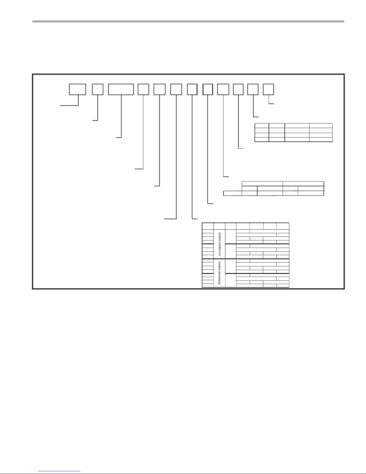
Model Nomenclature
1 2
TY
SERIES
TY = Tranquility® 22 Digital
CONFIGURATION
V = Vertical Up
H = Horizontal
UNIT SIZE
024
030
036
042
048
060
REVISION LEVEL
A = 030, 042, 048
B = 024, 036, 060
3
V
4 5 6 7
A0 2 4 DG 3 0 B L T
VOLTAGE
G = 208-230/60/1
E = 265/60/1
F = 460/60/3
H = 208-230/60/3
CONTROLS
D = DXM2
M = DXM2 w/LON
P = DXM2 w/MPC
Note: Above model nomenclature is a general reference. Consult individual engineering guides for
detailed information.
91011121314
8
Standard
WATER CIRCUIT OPTIONS
0 = None
CABINET
RANGE
ULTRA
QUIET
OPTION
1
A
J
K
2
C
L
M
3
E
N
P
4
G
R
S
15
S
STANDARD
S = Standard
SUPPLY AIR FLOW &
MOTOR CONFIGURATION
TTYV
BTYH
STYH
RETURN AIR FLOW CONFIGURATION
L = Left Return
R = Right Return
V = Left Return, Stainless Steel Drain Pan
W = Right Return, Stainless Steel Drain Pan
HEAT EXCHANGER OPTIONS
Non-Coated Air Coil
Copper
Cupro-Nickel
BG
2” FILTER
1” FILTER
RAIL
FRAME
NO
YES
NO
NO
NO
NO
YES
YES
YES
YES
NO
YES
NO
YES
NO
YES
YES
YES
1” FILTER
RAIL
YES
NO
NO
YES
NO
YES
NO
NO
YES
NO
Supply
Straight
NO
NO
NO
NO
Configuration
Top
Back
Tin Plated Air Coil
Copper
2” FILTER
FRAME
YES
NO
NO
YES
NO
NO
YES
NO
NO
YES
NO
NO
AJ
Cupro-Nickel
Rev.: 12/17/14
Motor
ECM
ECM
ECM
climatemaster.com
3
Page 4

CLIMATEMASTER WATER-SOURCE HEAT PUMPS
S
P
on
Tranquility
Rev.: 12/17/14
®
22 (TY) Series
General Information
Safety
Warnings, cautions, and notices appear throughout this
manual. Read these items carefully before attempting any
installation, service, or troubleshooting of the equipment.
DANGER: Indicates an immediate hazardous situation,
which if not avoided will result in death or serious injury.
DANGER labels on unit access panels must be observed.
WARNING: Indicates a potentially hazardous situation,
which if not avoided could result in death or serious injury.
CAUTION: Indicates a potentially hazardous situation or
an unsafe practice, which if not avoided could result in
minor or moderate injury or product or property damage.
NOTICE: Notifi cation of installation, operation, or
maintenance information, which is important, but which is
not hazard-related.
WARNING!
WARNING! To avoid the release of refrigerant into the
atmosphere, the refrigerant circuit of this unit must be
serviced only by technicians who meet local, state, and
federal profi ciency requirements.
CAUTION!
CAUTION! To avoid equipment damage, DO NOT use
these units as a source of heating or cooling during the
construction process. The mechanical components and fi lters
will quickly become clogged with construction dirt and debris,
which may cause system damage.
WARNING!
WARNING! The installation of water-source heat pumps and
all associated components, parts, and accessories which
make up the installation shall be in accordance with the
regulations of ALL authorities having jurisdiction and MUST
conform to all applicable codes. It is the responsibility of
the installing contractor to determine and comply with ALL
applicable codes and regulations.
torage
re-Installati
WARNING!
WARNING! All refrigerant discharged from this unit must
be recovered WITHOUT EXCEPTION. Technicians must
follow industry accepted guidelines and all local, state, and
federal statutes for the recovery and disposal of refrigerants.
If a compressor is removed from this unit, refrigerant circuit
oil will remain in the compressor. To avoid leakage of
compressor oil, refrigerant lines of the compressor must be
sealed after it is removed.
Inspection - Upon receipt of the equipment, carefully
check the shipment against the bill of lading. Make sure
all units have been received. Inspect the packaging of
each unit, and inspect each unit for damage. Ensure that
the carrier makes proper notation of any shortages or
damage on all copies of the freight bill and completes a
common carrier inspection report. Concealed damage
not discovered during unloading must be reported to the
carrier within 15 days of receipt of shipment. If not fi led
within 15 days, the freight company can deny the claim
without recourse.
Note: It is the responsibility of the purchaser to fi le all
necessary claims with the carrier. Notify your equipment
supplier of all damage within fi fteen (15) days of
shipment.
Storage - Equipment should be stored in its original
packaging in a clean, dry area. Store units in an upright
position at all times. Stack units a maximum of 3 units
high.
Unit Protection - Cover units on the job site with either
the original packaging or an equivalent protective
covering. Cap the open ends of pipes stored on the
job site. In areas where painting, plastering, and/or
spraying has not been completed, all due precautions
must be taken to avoid physical damage to the units
and contamination by foreign material. Physical damage
and contamination may prevent proper start-up and may
result in costly equipment clean-up.
4
ClimateMaster Water-Source Heat Pumps
Page 5

THE SMART SOLUTION FOR ENERGY EFFICIENCY
Examine all pipes, fi ttings, and valves before installing
any of the system components. Remove any dirt or debris
found in or on these components.
Pre-Installation - Installation, Operation, and
Maintenance instructions are provided with each unit.
Horizontal equipment is designed for installation
above false ceiling or in a ceiling plenum. Other unit
confi gurations are typically installed in a mechanical
room. The installation site chosen should include
adequate service clearance around the unit. Before unit
start-up, read all manuals and become familiar with the
unit and its operation. Thoroughly check the system
before operation.
Prepare units for installation as follows:
1. Compare the electrical data on the unit nameplate
with ordering and shipping information to verify that
the correct unit has been shipped.
2. Keep the cabinet covered with the original packaging
until installation is complete and all plastering,
painting, etc. is fi nished.
3. Verify refrigerant tubing is free of kinks or dents and
that it does not touch other unit components.
4. Inspect all electrical connections. Connections must
be clean and tight at the terminals.
5. Remove any blower support packaging (water-to-air
units only).
6. Loosen compressor bolts on units equipped with
compressor spring vibration isolation until the
compressor rides freely on the springs. Remove
shipping restraints. (No action is required for
compressors with rubber grommets.)
7. Some airfl ow patterns are fi eld convertible (horizontal
units only). Locate the airfl ow conversion section of
this IOM.
8. Locate and verify any hot water generator (HWG),
hanger, or other accessory kit located in the
compressor section or blower section.
Tranquility
®
22 (TY) Series
Rev.: 12/17/14
General Information
CAUTION!
CAUTION! All three phase scroll compressors must have
direction of rotation verifi ed at start-up. Verifi cation is
achieved by checking compressor Amp draw. Amp draw
will be substantially lower compared to nameplate values.
Additionally, reverse rotation results in an elevated sound
level compared to correct rotation. Reverse rotation will result
in compressor internal overload trip within several minutes.
Verify compressor type before proceeding.
CAUTION!
CAUTION! DO NOT store or install units in corrosive
environments or in locations subject to temperature or
humidity extremes (e.g., attics, garages, rooftops, etc.).
Corrosive conditions and high temperature or humidity can
signifi cantly reduce performance, reliability, and service life.
Always move and store units in an upright position. Tilting
units on their sides may cause equipment damage.
CAUTION!
CAUTION! CUT HAZARD - Failure to follow this caution may
result in personal injury. Sheet metal parts may have sharp
edges or burrs. Use care and wear appropriate protective
clothing, safety glasses and gloves when handling parts and
servicing heat pumps.
NOTICE! Failure to remove shipping brackets from
spring-mounted compressors will cause excessive
noise, and could cause component failure due to
added vibration.
climatemaster.com
5
Page 6
CLIMATEMASTER WATER-SOURCE HEAT PUMPS
Tranquility
Rev.: 12/17/14
®
22 (TY) Series
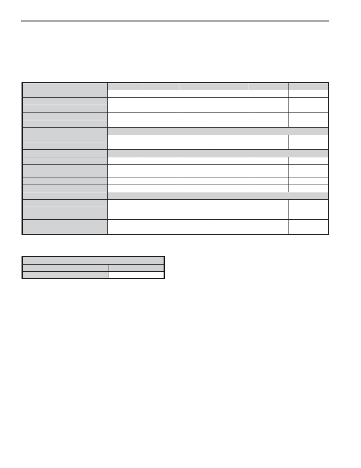
Unit Physical Data
Tranquility®
Factory Charge HFC-410A (oz) [kg] 49 48 48 70 80 84
PSC Fan Motor & Blower ECM
Blower Wheel Size (dia x w) - (in) [mm] 9X7 9X7 9X8 9X8 10X10 11X10
Air Coil Dimensions (h x w) - (in) [mm] 20 X 17.25 20 X 17.25 24 X 21.75 24 X 21.75 24x28.25 24x28.25
Standard Filter - 1" [25.4mm] Throwaway,
Air Coil Dimensions (h x w) - (in) [mm] 16 X 22 16 X 22 20 X 25 20 X 25 20 X 35 20 X 35
Standard Filter - 1" [25.4mm] Throwaway,
Notes:
All units have TXV expansion device and 1/2” & 3/4” electrical knockouts.
22 Two-Stage (TY) Series (60Hz Only)
Model 024 030 036 042 048 060
Compressor (1 Each) Scroll Scroll Scroll Scroll Scroll Scroll
Fan Motor (hp) [W] 1/2 1/2 1/2 3/4 3/4 1
Water Connection Size
FPT (in) 3/4" 3/4" 3/4" 3/4" 1" 1"
Coax Volume (gallons) 0.323 0.323 0.738 0.89 0.738 0.939
Vertical Upfl ow
qty (in) [mm]
Weight - Operating, (lbs) [kg] 189 197 203 218 263 278
Weight - Packaged, (lbs) [kg] 194 202 209 224 270 285
Horizontal
qty (in) [mm]
Weight - Operating, (lbs) [kg] 174 182 203 218 263 278
Weight - Packaged, (lbs) [kg] 179 187 209 224 270 285
20x20 20x20 24x24 24x24
18x25 18x25 2-14x20 2-14x20 1-20x24 1-14x20 1-20x24 1-14x20
1-14x24
1-18x24
1-14x24
1-18x24
Unit Maximum Water Working Pressure
Options
Base Unit
Use the lowest maximum pressure rating when multiple options are combined.
Max Pressure PSIG [kPa]
300 [2,068]
6
ClimateMaster Water-Source Heat Pumps
Page 7
THE SMART SOLUTION FOR ENERGY EFFICIENCY
Horizontal Unit Location
Units are not designed for outdoor installation. Locate
the unit in an INDOOR area that allows enough space
for service personnel to perform typical maintenance or
repairs without removing unit from the ceiling. Horizontal
units are typically installed above a false ceiling or in a
ceiling plenum. Never install units in areas subject to
freezing or where humidity levels could cause cabinet
condensation (such as unconditioned spaces subject
to 100% outside air). Consideration should be given to
access for easy removal of the fi lter and access panels.
Provide suffi cient room to make water, electrical, and
duct connection(s).
If the unit is located in a confi ned space, such as a closet,
provisions must be made for return air to freely enter the
space by means of a louvered door, etc. Any access panel
screws that would be diffi cult to remove after the unit
is installed should be removed prior to setting the unit.
Refer to Figure 3 for an illustration of a typical installation.
Refer to unit submittal data or engineering design guide
for dimensional data.
Conform to the following guidelines when selecting
unit location:
1. Provide a hinged access door in concealed-spline
or plaster ceilings. Provide removable ceiling
tiles in T-bar or lay-in ceilings. Refer to horizontal
unit dimensions for specifi c series and model in
unit submittal data. Size the access opening to
accommodate the service technician during the
removal or replacement of the compressor and the
removal or installation of the unit itself.
2. Provide access to hanger brackets, water valves and
fi ttings. Provide screwdriver clearance to access
panels, discharge collars and all electrical connections.
3. DO NOT obstruct the space beneath the unit with
piping, electrical cables and other items that prohibit
future removal of components or the unit itself.
4. Use a manual portable jack/lift to lift and support the
weight of the unit during installation and servicing.
The installation of water source heat pump units and all
associated components, parts and accessories which
make up the installation shall be in accordance with
the regulations of ALL authorities having jurisdiction
and MUST conform to all applicable codes. It is the
responsibility of the installing contractor to determine
and comply with ALL applicable codes and regulations.
Tranquility
®
22 (TY) Series
Rev.: 12/17/14
Horizontal Installation
Mounting Horizontal Units
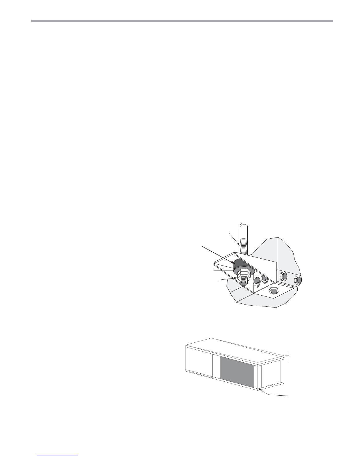
Horizontal units have hanger kits pre-installed from the
factory as shown in Figure 1. Figure 3 shows a typical
horizontal unit installation.
Horizontal heat pumps are typically suspended above
a ceiling or within a soffi t using fi eld supplied, threaded
rods sized to support the weight of the unit.
Use four (4) fi eld supplied threaded rods and factory
provided vibration isolators to suspend the unit. Hang
the unit clear of the fl oor slab above and support the
unit by the mounting bracket assemblies only. DO NOT
attach the unit fl ush with the fl oor slab above.
Pitch the unit toward the drain as shown in Figure 2 to
improve the condensate drainage. On small units (less
than 2.5 tons/8.8kW) ensure that unit pitch does not
cause condensate leaks inside the cabinet.
Figure 1: Hanger Bracket
>PP@7KUHDGHG
5RGE\RWKHUV
9LEUDWLRQ,VRODWRU
IDFWRU\VXSSOLHG
:DVKHU
E\RWKHUV
'RXEOH+H[1XWV
E\RWKHUV
Figure 2: Horizontal Unit Pitch
1/4” (6.4mm) pitch
toward drain for drainage
Drain Connection
climatemaster.com
7
Page 8

CLIMATEMASTER WATER-SOURCE HEAT PUMPS
Tranquility
Rev.: 12/17/14
®
22 (TY) Series
Horizontal Installation
Figure 3: Typical Horizontal Unit Installation
Power Wiring
Supply Air
Unit Power
Insulated supply duct with
at least one 90 deg elbow
to reduce air noise
Flexible Duct
Connector
Unit Power
Disconnect
(by others)
Unit Hanger
Return Air
Thermostat
Wiring
Optional Water Control Valve
Stainless steel braid hose
with integral "J" swivel
Ball Valve with optional
integral P/T plug
Building
Loop
Air Coil - To obtain maximum performance, the air coil
should be cleaned before start-up. A 10% solution of
dishwasher detergent and water is recommended for
both sides of the coil. A thorough water rinse should
follow. UV based anti-bacterial systems may damage
coated air coils.
Notice! Installation Note - Ducted Return: Many
horizontal WSHPs are installed in a return air ceiling
plenum application (above ceiling). Vertical WSHPs are
commonly installed in a mechanical room with free return
(e.g. louvered door). Therefore, fi lter rails are the industry
standard and are included on ClimateMaster commercial
heat pumps for the purposes of holding the fi lter only.
For ducted return applications, the fi lter rail must be
removed and replaced with a duct fl ange or fi lter frame.
Canvas or fl exible connectors should also be used to
minimize vibration between the unit and ductwork.
8
ClimateMaster Water-Source Heat Pumps
Page 9
THE SMART SOLUTION FOR ENERGY EFFICIENCY
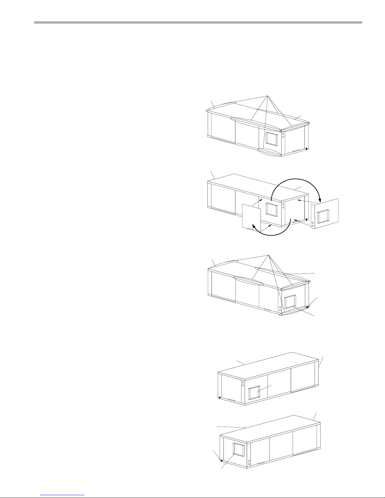
Overview - Horizontal units can be fi eld converted
between side (straight) and back (end) discharge using
the instructions below.
Note: It is not possible to fi eld convert return air
between left or right return models due to the
necessity of refrigeration copper piping changes.
Preparation - It is best to fi eld convert the unit on the
ground before hanging. If the unit is already hung it
should be taken down for the fi eld conversion.
Side to Back Discharge Conversion
1. Place unit in well lit area. Remove the screws as shown
in Figure 4 to free top panel and discharge panel.
2. Lift out the access panel and set aside. Lift and rotate
the discharge panel to the other position as shown,
being careful with the blower wiring.
3. Check blower wire routing and connections for
tension or contact with sheet metal edges. Re-route if
necessary.
4. Check refrigerant tubing for contact with other
components.
5. Reinstall top panel and screws noting that the location
for some screws will have changed.
6. Manually spin the fan wheel to ensure that the wheel
is not rubbing or obstructed.
7. Replace access panels.
Tranquility
Field Conversion of Air Discharge
Figure 4: Left Return Side to Back
Water
Connection End
Water
Connection End
Water
Connection End
Side Discharge
Remove Screws
Rotate
Move to Side
Replace Screws
®
22 (TY) Series
Rev.: 12/17/14
Return Air
Return Air
Return Air
Back to Side Discharge Conversion - If the discharge is
changed from back to side, use above instruction noting
that illustrations will be reversed.
Left vs. Right Return - It is not possible to fi eld convert
return air between left or right return models due to
the necessity of refrigeration copper piping changes.
However, the conversion process of side to back or
back to side discharge for either right or left return
confi guration is the same. In some cases, it may be
possible to rotate the entire unit 180 degrees if the return
air connection needs to be on the opposite side. Note
that rotating the unit will move the piping to the
other end of the unit.
Back Discharge
Figure 5: Right Return Side to Back
Return Air
Supply Duct
Side Discharge
Return Air
Drain
Discharge Air
Back Discharge
Drain
Discharge Air
Water
Connection End
Water
Connection End
climatemaster.com
9
Page 10
CLIMATEMASTER WATER-SOURCE HEAT PUMPS
C
n
Tranquility
Rev.: 12/17/14
®
22 (TY) Series
ondensate Piping
Duct System Installatio
Horizontal Installation
Condensate Piping - Horizontal Units - A condensate
drain line must be installed and pitched away for the unit
to allow for proper drainage. This connection must meet
all local plumbing/building codes.
Pitch the unit toward the drain as shown in Figure 2 to
improve the condensate drainage. On small units (less
than 2.5 tons/8.8 kW), ensure that unit pitch does not
cause condensate leaks inside the cabinet.
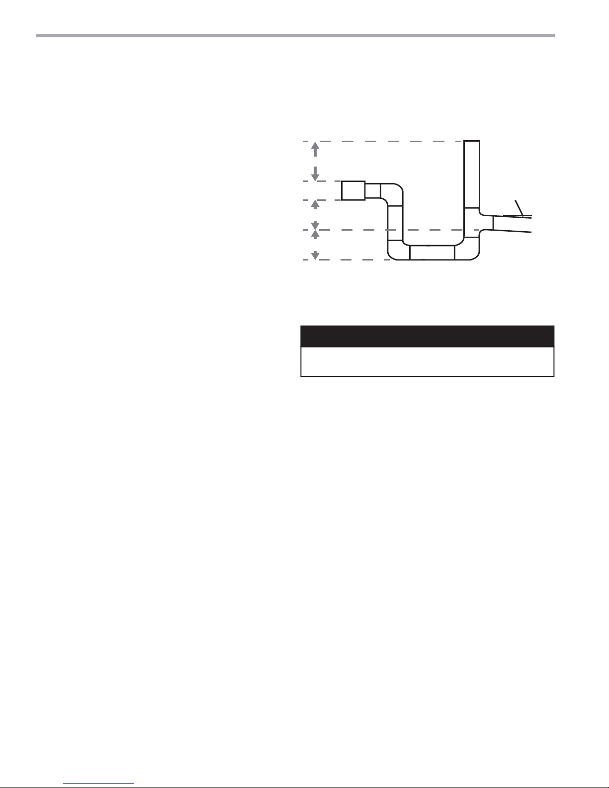
Install condensate trap at each unit with the top of
the trap positioned below the unit condensate drain
connection as shown in Figure 6. Design the depth of
the trap (water-seal) based upon the amount of ESP
capability of the blower (where 2 inches [51mm] of ESP
capability requires 2 inches [51mm] of trap depth).
As a general rule, 1-1/2 inch [38mm] trap depth is the
minimum.
Each unit must be installed with its own individual trap
and connection to the condensate line (main) or riser.
Provide a means to fl ush or blow out the condensate line.
DO NOT install units with a common trap and/or vent.
Figure 6: Horizontal Condensate Connection
ರ
ರ3HU
)RRW
ರ
ರ
* Some units include a painted drain connection.
Using a threaded pipe or similar device to clear
any excess paint accumulated inside this fitting
may ease final drain line installation.
CAUTION!
CAUTION! Ensure condensate line is pitched toward drain
1/8 inch per ft [11mm per m] of run.
Always vent the condensate line when dirt or air
can collect in the line or a long horizontal drain line
is required. Also vent when large units are working
against higher external static pressure than other units
connected to the same condensate main since this may
cause poor drainage for all units on the line. WHEN A
VENT IS INSTALLED IN THE DRAIN LINE, IT MUST BE
LOCATED AFTER THE TRAP IN THE DIRECTION OF
THE CONDENSATE FLOW.
Duct System Installation - Proper duct sizing and design
is critical to the performance of the unit. The duct system
should be designed to allow adequate and even airfl ow
through the unit during operation. Air fl ow through
the unit MUST be at or above the minimum stated
airfl ow for the unit to avoid equipment damage. Duct
systems should be designed for quiet operation. Refer
to Figure 3 for horizontal duct system details or Figure
8 for vertical duct system details. A fl exible connector
is recommended for both discharge and return air duct
connections on metal duct systems to eliminate the
transfer of vibration to the duct system. To maximize
sound attenuation of the unit blower, the supply and
return plenums should include internal fi berglass duct
liner or be constructed from ductboard for the fi rst few
feet. Application of the unit to uninsulated ductwork in an
unconditioned space is not recommended, as the unit’s
performance may be adversely affected.
10
At least one 90° elbow should be included in the supply
duct to reduce air noise. If air noise or excessive air fl ow
is a problem, the blower speed can be changed. For
airfl ow charts, consult submittal data for the series and
model of the specifi c unit.
If the unit is connected to existing ductwork, a previous
check should have been made to ensure that the
ductwork has the capacity to handle the airfl ow required
for the unit. If ducting is too small, as in the replacement
of a heating only system, larger ductwork should be
installed. All existing ductwork should be checked for
leaks and repaired as necessary.
ClimateMaster Water-Source Heat Pumps
Page 11
THE SMART SOLUTION FOR ENERGY EFFICIENCY
on
Vertical Unit Location - Units are not designed for
outdoor installation. Locate the unit in an INDOOR
area that allows enough space for service personnel to
perform typical maintenance or repairs without removing
unit from the mechanical room/closet. Vertical units
are typically installed in a mechanical room or closet.
Never install units in areas subject to freezing or where
humidity levels could cause cabinet condensation (such
as unconditioned spaces subject to 100% outside air).
Consideration should be given to access for easy removal
of the fi lter and access panels. Provide suffi cient room to
make water, electrical, and duct connection(s).
If the unit is located in a confi ned space, such as a closet,
provisions must be made for return air to freely enter
the space by means of a louvered door, etc. Any access
panel screws that would be diffi cult to remove after
the unit is installed should be removed prior to setting
the unit. Refer to Figures 7 and 8 for typical installation
illustrations. Refer to unit submittal data or engineering
design guide for dimensional data.
Tranquility
Vertical Unit Locati
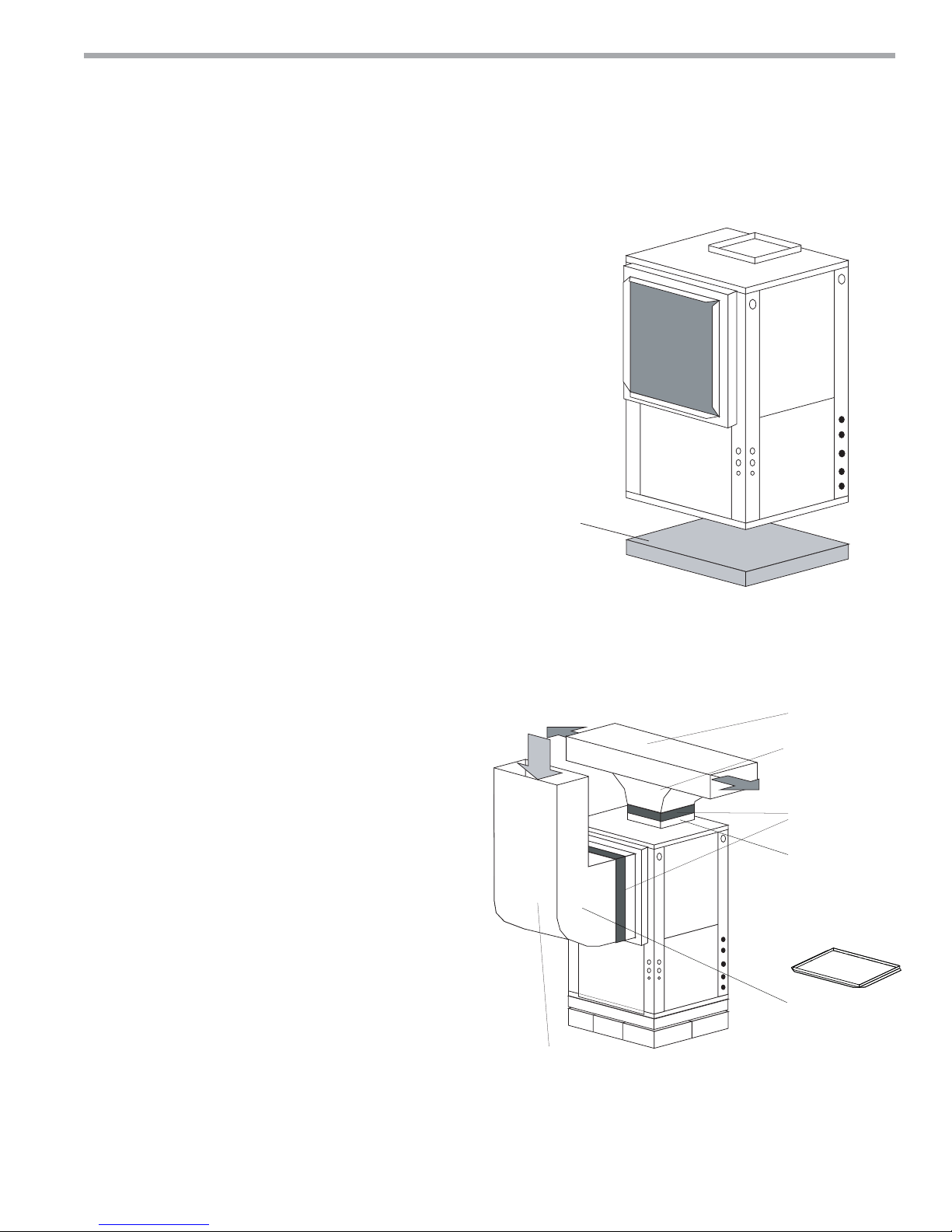
Figure 7: Vertical Unit Mounting
$LU3DGRUH[WUXGHG
SRO\VW\UHQHLQVXODWLRQERDUG
®
22 (TY) Series
Rev.: 12/17/14
Vertical Installation
1. Install the unit on a piece of rubber, neoprene or
other mounting pad material for sound isolation. The
pad should be at least 3/8” [10mm] to 1/2” [13mm] in
thickness. Extend the pad beyond all four edges of
the unit.
2. Provide adequate clearance for fi lter replacement
and drain pan cleaning. Do not block fi lter access
with piping, conduit or other materials. Refer to
unit submittal data or engineering design guide for
dimensional data.
3. Provide access for fan and fan motor maintenance
and for servicing the compressor and coils without
removing the unit.
4. Provide an unobstructed path to the unit within the
closet or mechanical room. Space should be suffi cient
to allow removal of the unit, if necessary.
5. Provide access to water valves and fi ttings and
screwdriver access to the unit side panels, discharge
collar and all electrical connections.
Notice! Installation Note - Ducted Return: Many
horizontal WSHPs are installed in a return air ceiling
plenum application (above ceiling). Vertical WSHPs are
commonly installed in a mechanical room with free return
(e.g. louvered door). Therefore, fi lter rails are the industry
standard and are included on ClimateMaster commercial
heat pumps for the purposes of holding the fi lter only.
For ducted return applications, the fi lter rail must be
removed and replaced with a duct fl ange or fi lter frame.
Canvas or fl exible connectors should also be used to
minimize vibration between the unit and ductwork.
Figure 8: Typical Vertical Unit Installation Using
Ducted Return Air
Internally insulate return
transition duct to reduce noise
climatemaster.com
Internally insulate supply
duct for first 1.2 m each way
to reduce noise
Use turning vanes in
supply transition
Flexible canvas duct
connector to reduce
noise and vibration
Remove supply duct
flanges from inside blower
compartment and install
on supply air opening of
unit. Do not use a supply
air plenum/duct smaller
than the size of the supply
duct flanges.
Rounded return
transition
Rev.: 2/13
11
Page 12
CLIMATEMASTER WATER-SOURCE HEAT PUMPS
Tranquility
Rev.: 12/17/14
®
22 (TY) Series
Vertical Installation
Sound Attenuation for Vertical Units - Sound
attenuation is achieved by enclosing the unit within a
small mechanical room or a closet. Additional measures
for sound control include the following:
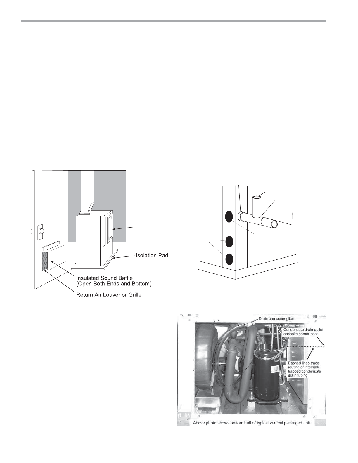
1. Mount the unit so that the return air inlet is 90° to the
return air grille. Refer to Figure 9. Install a sound baffl e
as illustrated to reduce line-of sight sound transmitted
through return air grilles.
2. Mount the unit on a rubber or neoprene isolation pad
to minimize vibration transmission to the building
structure.
Figure 9: Vertical Sound Attenuation
Condensate Piping for Vertical Units - A condensate
line must be installed and pitched away from the unit to
allow for proper drainage. This connection must meet
all local plumbing/building codes. Vertical units utilize
a condensate hose inside the cabinet as a trapping
loop; therefore an external trap is not necessary. Figure
10a shows typical condensate connections. Figure 10b
illustrates the internal trap for a typical vertical heat
pump. Each unit must be installed with its own individual
vent (where necessary) and a means to fl ush or blow
out the condensate drain line. Do not install units with a
common trap and/or vent.
Figure 10a: Vertical Condensate Drain
*3/4" FPT
Vent
3/4" PVC
1/8" per foot
slope to drain
Return
Air Inlet
Notice! Units with clear plastic drain lines should
have regular maintenance (as required) to avoid
buildup of debris, especially in new construction.
Water
Connections
* Some units include a painted drain connection. Using a
threaded pipe or similar device to clear any excess paint
accumulated inside this fitting may ease final drain line installation.
Alternate
Condensate
Location
Figure 10b: Vertical Internal Condensate Trap
12
ClimateMaster Water-Source Heat Pumps
Page 13
THE SMART SOLUTION FOR ENERGY EFFICIENCY
Installation of Supply and Return Piping
Follow these piping guidelines.
1. Install a drain valve at the base of each supply and
return riser to facilitate system fl ushing.
2. Install shut-off / balancing valves and unions at each
unit to permit unit removal for servicing.
3. Place strainers at the inlet of each system circulating
pump.
4. Select the proper hose length to allow slack between
connection points. Hoses may vary in length by +2%
to -4% under pressure.
5. Refer to Table 1. Do not exceed the minimum bend
radius for the hose selected. Exceeding the minimum
bend radius may cause the hose to collapse, which
reduces water fl ow rate. Install an angle adapter to
avoid sharp bends in the hose when the radius falls
below the required minimum.
Tranquility
®
22 (TY) Series
Rev.: 12/17/14
Piping Installation
WARNING!
WARNING! Polyolester Oil, commonly known as POE oil, is
a synthetic oil used in many refrigeration systems including
those with HFC-410A refrigerant. POE oil, if it ever comes
in contact with PVC or CPVC piping, may cause failure of
the PVC/CPVC. PVC/CPVC piping should never be used
as supply or return water piping with water source heat
pump products containing HFC-410A as system failures and
property damage may result.
CAUTION!
CAUTION! Corrosive system water requires corrosion
resistant fi ttings and hoses, and may require water treatment.
CAUTION!
CAUTION! Do not bend or kink supply lines or hoses.
Insulation is not required on loop water piping except
where the piping runs through unheated areas, outside
the building or when the loop water temperature is
below the minimum expected dew point of the pipe
ambient conditions. Insulation is required if loop water
temperature drops below the dew point (insulation is
required for ground loop applications in most climates).
Pipe joint compound is not necessary when Tefl on®
thread tape is pre-applied to hose assemblies or when
fl ared-end connections are used. If pipe joint compound
is preferred, use compound only in small amounts on
the external pipe threads of the fi tting adapters. Prevent
sealant from reaching the fl ared surfaces of the joint.
Note: When antifreeze is used in the loop, ensure that
it is compatible with the Tefl on
®
tape or pipe joint
compound that is applied.
Maximum allowable torque for brass fi ttings is 30 ft-lbs
[41 N-m]. If a torque wrench is not available, tighten
fi nger-tight plus one quarter turn. Tighten steel fi ttings
as necessary.
Optional pressure-rated hose assemblies designed
specifi cally for use with ClimateMaster units are available.
Similar hoses can be obtained from alternate suppliers.
Supply and return hoses are fi tted with swivel-joint fi ttings
at one end to prevent kinking during installation.
CAUTION!
CAUTION! Piping must comply with all applicable codes.
Table 1: Metal Hose Minimum Bend Radii
Hose Diameter Minimum Bend Radii
1/2" [12.7mm] 2-1/2" [6.4cm]
3/4" [19.1mm] 4" [10.2cm]
1" [25.4mm] 5-1/2" [14cm]
1-1/4" [31.8mm] 6-3/4" [17.1cm]
NOTICE! Do not allow hoses to rest against structural
building components. Compressor vibration may
be transmitted through the hoses to the structure,
causing unnecessary noise complaints.
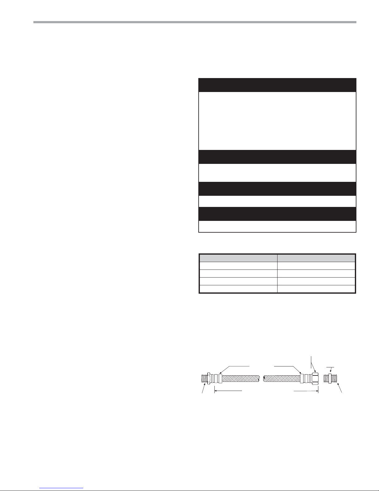
Figure 11: Supply/Return Hose Kit
MPT
Rib Crimped
Length
(2 ft [0.6m] Length Standard)
Swivel
Brass
Fitting
Brass
Fitting
MPT
Refer to Figure 11 for an illustration of a typical supply/
return hose kit. Adapters secure hose assemblies to the
unit and risers. Install hose assemblies properly and check
regularly to avoid system failure and reduced service life.
climatemaster.com
13
Page 14

CLIMATEMASTER WATER-SOURCE HEAT PUMPS
Tranquility
Rev.: 12/17/14
®
22 (TY) Series
Water-Loop Heat Pump Applications
Commercial Water Loop Applications
Commercial systems typically include a number of
units connected to a common piping system. Any unit
plumbing maintenance work can introduce air into the
piping system; therefore air elimination equipment
is a major portion of the mechanical room plumbing.
Consideration should be given to insulating the
piping surfaces to avoid condensation. ClimateMaster
recommends unit insulation any time the water
temperature is expected to be below 60ºF (15.6ºC). Metal
to plastic threaded joints should never be used due to
their tendency to leak over time.
®
Tefl o n
minimize internal fouling of the heat exchanger. Do
not over tighten connections and route piping so as
not to interfere with service or maintenance access.
Hose kits are available from ClimateMaster in different
confi gurations for connection between the unit and the
piping system. Depending upon selection, hose kits
may include shut off valves, P/T plugs for performance
measurement, high pressure stainless steel braided hose,
“Y” type strainer with blow down valve, and/or “J” type
swivel connection.
tape thread sealant is recommended to
The piping system should be fl ushed to remove dirt,
piping chips, and other foreign material prior to
operation (see “Piping System Cleaning and Flushing
Procedures” in this manual). The fl ow rate is usually set
between 2.25 and 3.5 gpm per ton [2.9 and 4.5 l/m per
kW] of cooling capacity. ClimateMaster recommends 3
gpm per ton [3.9 l/m per kW] for most applications of
water loop heat pumps. To ensure proper maintenance
and servicing, P/T ports are imperative for temperature
and fl ow verifi cation, as well as performance checks.
Water loop heat pump (cooling tower/boiler) systems
typically utilize a common loop, maintained between
60 - 90°F [16 - 32°C]. The use of a closed circuit evaporative
cooling tower with a secondary heat exchanger between
the tower and the water loop is recommended. If an
open type cooling tower is used continuously, chemical
treatment and fi ltering will be necessary.
Typical Water-Loop Application
3/8" [10mm] threaded rods
(by others)
Optional Water Control Valve
Stainless steel braid hose
with integral "J" swivel
Ball Valve with optional
integral P/T plug
Building
Loop
Supply Air
Insulated supply duct with
at least one 90 deg elbow
to reduce air noise
Power Wiring
Unit Power
Disconnect
(by others)
Unit Hanger
Return Air
Unit Power
Thermostat
Wiring
Low Water Temperature Cutout Setting - DXM2 Control
When antifreeze is selected, the LT1 jumper (JW3) should be clipped to select the low temperature (antifreeze 10.0°F
[-12.2°C]) setpoint and avoid nuisance faults (see “Low Water Temperature Cutout Selection” in this manual). Note:
Low water temperature operation requires extended range equipment.
14
ClimateMaster Water-Source Heat Pumps
Page 15
THE SMART SOLUTION FOR ENERGY EFFICIENCY
CAUTION!
CAUTION! The following instructions represent industry
accepted installation practices for closed loop earth coupled
heat pump systems. Instructions are provided to assist the
contractor in installing trouble free ground loops. These
instructions are recommendations only. State/provincial
and local codes MUST be followed and installation MUST
conform to ALL applicable codes. It is the responsibility of
the installing contractor to determine and comply with ALL
applicable codes and regulations.
CAUTION!
CAUTION! Ground loop applications require extended range
equipment and optional refrigerant/water circuit insulation.
Pre-Installation
Prior to installation, locate and mark all existing
underground utilities, piping, etc. Install loops for new
construction before sidewalks, patios, driveways, and other
construction has begun. During construction, accurately
mark all ground loop piping on the plot plan as an aid in
avoiding potential future damage to the installation.
Piping Installation
The typical closed loop ground source system is shown in
Figure 13. All earth loop piping materials should be limited
to polyethylene fusion only for in-ground sections of the
loop. Galvanized or steel fi ttings should not be used at any
time due to their tendency to corrode. All plastic to metal
threaded fi ttings should be avoided due to their potential
to leak in earth coupled applications. A fl anged fi tting
should be substituted. P/T plugs should be used with units
that do not include vFlow so that fl ow can be measured
using the pressure drop of the unit heat exchanger. Units
equipped with any of the four vFlow confi gurations have
built in Schrader ports. Water temperature may be viewed
on the iGate communicating thermostat.
Earth loop temperatures can range between 25 and 110°F
[-4 to 43°C]. Flow rates between 2.25 and 3 gpm [2.41 to
3.23 l/m per kW] of cooling capacity is recommended in
these applications.
Tranquility
®
22 (TY) Series
Rev.: 12/17/14
Ground-Loop Heat Pump Applications
Test individual horizontal loop circuits before backfi lling.
Test vertical U-bends and pond loop assemblies prior to
installation. Pressures of at least 100 psi [689 kPa] should
be used when testing. Do not exceed the pipe pressure
rating. Test entire system when all loops are assembled.
Flushing the Earth Loop
Upon completion of system installation and testing, fl ush
the system to remove all foreign objects and purge to
remove all air.
Antifreeze
I
n areas where minimum entering loop temperatures
drop below 40°F [5°C] or where piping will be routed
through areas subject to freezing, antifreeze is required.
Alcohols and glycols are commonly used as antifreeze;
however your local sales offi ce should be consulted to
determine the antifreeze best suited to your area. Freeze
protection should be maintained to 15°F [9°C] below
the lowest expected entering loop temperature. For
example, if 30°F [-1°C] is the minimum expected entering
loop temperature, the leaving loop temperature would
be 22 to 25°F [-6 to -4°C] and freeze protection should be
at 15°F [-10°C]. Calculation is as follows:
30°F - 15°F = 15°F [-1°C - 9°C = -10°C].
All alcohols should be premixed and pumped from
a reservoir outside of the building when possible or
introduced under the water level to prevent fumes.
Calculate the total volume of fl uid in the piping system.
Then use the percentage by volume shown in table
2 for the amount of antifreeze needed. Antifreeze
concentration should be checked from a well mixed
sample using a hydrometer to measure specifi c gravity.
Low Water Temperature Cutout Setting - DXM2
Control
When antifreeze is selected, the LT1 jumper (JW3) should
be clipped to select the low temperature (antifreeze
10.0°F [-12.2°C]) setpoint and avoid nuisance faults (see
“Low Water Temperature Cutout Selection” in this
manual). Note: Low water temperature operation
requires extended range equipment.
Table 2: Antifreeze Percentages by Volume
Type
Methanol
100% USP food grade Propylene Glycol
Ethanol*
* Must not be denatured with any petroleum based product
Minimum Temperature for Low Temperature Protection
10°F [-12.2°C] 15°F [-9.4°C] 20°F [-6.7°C] 25°F [-3.9°C]
25%
38%
29%
climatemaster.com
21%
25%
25%
16%
22%
20%
10%
15%
14%
15
Page 16

CLIMATEMASTER WATER-SOURCE HEAT PUMPS
Tranquility
Rev.: 12/17/14
®
22 (TY) Series
Ground-Loop and Ground Water Heat Pump Applications
Ground-Loop Heat Pump Applications
Typical Closed Loop with Central Pumping
T o Thermostat
Water Out
High and
Low Voltage
Knockouts
Water In
Shut Off
Ball Valves
for Isolation
Vibration Isolation Pad
Ground Water Heat Pump Applications
Typical Open Loop/Well
T o Thermostat
High and
Low Voltage
Knockouts
Optional
Filter
Boiler
Drains
Pressure
Tank
Shut Off
Ball Valves
for Isolation
Water Out
Water In
Vibration Isolation Pad
16
ClimateMaster Water-Source Heat Pumps
Page 17
THE SMART SOLUTION FOR ENERGY EFFICIENCY
Open Loop - Ground Water Systems
ppp
p
Open Loop - Ground Water Systems
loop piping is shown in accompanying illustration. Shut
off valves should be included for ease of servicing. Boiler
drains or other valves should be “tee’d” into the lines to
allow acid fl ushing of the heat exchanger. Shut off valves
should be positioned to allow fl ow through the coax via the
boiler drains without allowing fl ow into the piping system.
P/T plugs should be used so that flow can be measured
using the pressure drop of the unit heat exchanger. Water
temperature may be viewed on the iGate communicating
thermostat. Supply and return water piping materials
should be limited to copper, HPDE, or other acceptable
high temperature material. Note that PVC or CPVC
material is not recommended as they are not compatible
with the polyolester oil used in HFC-410A products.
- Typical open
WARNING!
WARNING! Polyolester Oil, commonly known as POE oil, is
a synthetic oil used in many refrigeration systems including
those with HFC-410A refrigerant. POE oil, if it ever comes
in contact with PVC or CPVC piping, may cause failure of
the PVC/CPVC. PVC/CPVC piping should never be used
as supply or return water piping with water source heat
pump products containing HFC-410A as system failures and
property damage may result.
Tranquility
®
22 (TY) Series
Rev.: 12/17/14
Ground-Water Heat Pump Applications
Water Quality Standards
for water quality requirements. Scaling potential should be
assessed using the pH/Calcium hardness method. If the pH
<7.5 and the calcium hardness is less than 100 ppm, scaling
potential is low. If this method yields numbers out of range
of those listed, the Ryznar Stability and Langelier Saturation
indecies should be calculated. Use the appropriate scaling
surface temperature for the application, 150°F [66°C] for
direct use (well water/open loop); 90°F [32°F] for indirect
use. A monitoring plan should be implemented in these
probable scaling situations. Other water quality issues
such as iron fouling, corrosion prevention and erosion and
clogging should be referenced in Table 3.
Expansion Tank and Pump
expansion tank to minimize mineral formation due to air
exposure. The expansion tank should be sized to provide
at least one minute continuous run time of the pump using
its drawdown capacity rating to prevent pump short cycling.
Discharge water from the unit is not contaminated in any
manner and can be disposed of in various ways, depending
on local building codes (e.g. recharge well, storm sewer,
drain fi eld, adjacent stream or pond, etc.). Most local codes
forbid the use of sanitary sewer for disposal. Consult your
local building and zoning department to assure compliance
in your area.
- Table 3 should be consulted
- Use a closed, bladder-type
Water quantity should be plentiful and of good quality.
Consult table 3 for water quality guidelines. The unit can
be ordered with either a copper or cupro-nickel water heat
exchanger. Consult Table 3 for recommendations. Copper
is recommended for closed loop systems and open
loop ground water systems that are not high in mineral
content or corrosiveness. In conditions anticipating heavy
scale formation or in brackish water, a cupro-nickel heat
exchanger is recommended. In ground water situations
where scaling could be heavy or where biological growth
such as iron bacteria will be present, an open loop system
is not recommended. Heat exchanger coils may over
time lose heat exchange capabilities due to build up of
mineral deposits. Heat exchangers must only be serviced
by a qualifi ed technician, as acid and special pumping
equipment is required. Desuperheater coils can likewise
become scaled and possibly plugged. In areas with
extremely hard water, the owner should be informed that
the heat exchanger may require occasional acid fl ushing.
In some cases, the desuperheater option should not be
recommended due to hard water conditions and additional
maintenance required.
Water Control Valve
the heat exchanger by placing the water control valve(s)
on the discharge line to prevent mineral precipitation
during the off-cycle. Pilot operated slow closing valves are
recommended to reduce water hammer. If water hammer
persists, a mini-expansion tank can be mounted on the
piping to help absorb the excess hammer shock. Ensure that
the total ‘VA’ draw of the valve can be supplied by the unit
transformer. For instance, a slow closing valve can draw up
to 35VA. This can overload smaller 40 or 50 VA transformers
depending on the other controls in the circuit. A typical pilot
operated solenoid valve draws approximately 15VA. Note
the special wiring diagrams for slow closing valves (shown
later in this manual).
- Always maintain water pressure in
climatemaster.com
17
Page 18

CLIMATEMASTER WATER-SOURCE HEAT PUMPS
Tranquility
Rev.: 12/17/14
®
22 (TY) Series
Ground-Water Heat Pump Applications
Flow Regulation
by two methods. One method of fl ow regulation involves
simply adjusting the ball valve or water control valve on
the discharge line. Measure the pressure drop through the
unit heat exchanger, and determine fl ow rate from Tables
8a through 8e. Since the pressure is constantly varying, two
pressure gauges may be needed. Adjust the valve until
the desired fl ow of 1.5 to 2 gpm per ton [2.0 to 2.6 l/m per
kW] is achieved. A second method of fl ow control requires
a fl ow control device mounted on the outlet of the water
control valve. The device is typically a brass fi tting with
an orifi ce of rubber or plastic material that is designed
to allow a specifi ed fl ow rate. On occasion, fl ow control
devices may produce velocity noise that can be reduced by
applying some back pressure from the ball valve located
on the discharge line. Slightly closing the valve will spread
the pressure drop over both devices, lessening the velocity
noise.
- Flow regulation can be accomplished
Note: When EWT is below 50°F [10°C], 2 gpm per
ton (2.6 l/m per kW) is required.
Water Coil Low Temperature Limit Setting
- For all
open loop systems the 30°F [-1.1°C] LT1 setting (factory
setting-water) should be used to avoid freeze damage to
the unit. See “Low Water Temperature Cutout Selection” in
this manual for details on the low limit setting.
18
ClimateMaster Water-Source Heat Pumps
Page 19
THE SMART SOLUTION FOR ENERGY EFFICIENCY
Tranquility
®
22 (TY) Series
Water Quality Standards
Table 3: Water Quality Standards
Water Quality
Parameter
Scaling Potential - Primary Measurement
Above the given limits, scaling is likely to occur. Scaling indexes should be calculated using the limits below
pH/Calcium Hardness
Method
Index Limits for Probable Scaling Situations - (Operation outside these limits is not recommended)
Scaling indexes should be calculated at 66°C for direct use and HWG applications, and at 32°C for indirect HX use.
A monitoring plan should be implemented.
Ryznar
Stability Index If >7.5 minimize steel pipe use.
Langelier
Saturation Index
Iron Fouling
Iron Fe2+(Ferrous)
(Bacterial Iron potential)
Iron Fouling
Corrosion Prevention
pH
Hydrogen Sulfide (H
Ammonia ion as hydroxide, chloride,
nitrate and sulfate compounds
Maximum
Chloride Levels
S)
2
Erosion and Clogging
Particulate Size and
Erosion
The ClimateMaster Water Quality Table provides water quality requirements for ClimateMaster coaxial heat exchangers. The water should be evaluated by an
independent testing facility comparing to this Table and when properties are outside of these requirements, an external secondary heat exchanger must be used to
isolate the heat pump heat exchanger from the unsuitable water. Failure to do so will void the warranty for the coaxial heat exchanger and any other components
damaged by a leak.
Notes:
• Closed Recirculating system is identified by a
• Recirculating open wells should observe the open recirculating design considerations.
• NR - Application not recommended.
• "-" No design Maximum.
HX
Material
All
All
All
All
All
All
All
All
Copper
Cupronickel
304 S
S - <400 ppm <250 ppm <150 ppm
316 S
S - <1000 ppm <550 ppm < 375 ppm
Titanium - >1000 ppm >550 ppm >375 ppm
All
closed pressurized piping system.
Closed
Recirculating
-
- 6.0 - 7.5
-
-
-
6 - 8.5
Monitor/treat as
needed
- <0.5 ppm
-
- <20ppm NR NR
- <150 ppm NR NR
<10 ppm of particles
and a maximum
velocity of 1.8 m/s
Filtered for maximum
841 micron [0.84 mm,
20 mesh] size.
Open Loop and Recirculating Well
pH < 7.5 and Ca Hardness <100ppm
If <-0.5 minimize steel pipe use. Based upon 66°C HWG and
2+
(ferrous)>0.2 ppm with pH 6 - 8, O2<5 ppm check for iron bacteria.
If Fe
Above this level deposition will occur.
Minimize steel pipe below 7 and no open tanks with pH <8
At H
S>0.2 ppm, avoid use of copper and copper nickel piping or HX's.
2
Copper alloy (bronze or brass) cast components are OK to <0.5 ppm.
<10 ppm (<1 ppm "sandfree” for reinjection) of particles and a maximum
velocity of 1.8 m/s. Filtered for maximum 841 micron 0.84 mm,
20 mesh] size. Any particulate that is not removed can potentially
clog components.
Rotten egg smell appears at 0.5 ppm level.
Maximum Allowable at maximum water temperature.
10$C24$C38
-0.5 to +0.5
Direct well, 29°C Indirect Well HX
<0.2 ppm (Ferrous)
<0.5 ppm of Oxygen
6 - 8.5
<0.5 ppm
Rev.: 12/17/14
C
Rev.: 5/6/2014 S
climatemaster.com
19
Page 20
CLIMATEMASTER WATER-SOURCE HEAT PUMPS
Tranquility
Rev.: 12/17/14
®
22 (TY) Series
Electrical - Line Voltage
Electrical - Line Voltage
including electrical ground, must comply with the National
Electrical Code as well as all applicable local codes. Refer
to the unit electrical data for fuse sizes. Consult wiring
diagram for fi eld connections that must be made by
the installing (or electrical) contractor. All fi nal electrical
connections must be made with a length of fl exible conduit
to minimize vibration and sound transmission to the
building.
General Line Voltage Wiring
power is the same voltage and phase shown on the unit
serial plate. Line and low voltage wiring must be done in
accordance with local codes or the National Electric Code,
whichever is applicable.
Transformer
- All 208/230 voltage units are factory wired
for 208 volt. If supply voltage is 230 volt, installer must
rewire transformer. See wire diagram for connections.
- All fi eld installed wiring,
- Be sure the available
WARNING!
WARNING! To avoid possible injury or death due to electrical
shock, open the power supply disconnect switch and secure
it in an open position during installation.
CAUTION!
CAUTION! Use only copper conductors for fi eld installed
electrical wiring. Unit terminals are not designed to accept
other types of conductors.
Standard Unit
Compressor
RLA LRA Qty
Fan Motor
FLA
Total Unit
FLA
Min Circ
Amp
Max Fuse/
HACR
024
030
036
042
048
060
Voltage
Code
G 208/230/60/1 197/252 11.7 58.3 1 3.9 15.6 18.5 30
E 265/60/1 239/292 9.1 54.0 1 3.2 12.3 14.6 20
H 208/230/60/3 197/252 6.5 55.4 1 3.9 10.4 12.0 15
F* 460/60/3* 414/506 3.5 28.0 1 3.2 6.7 7.6 15
G 208/230/60/1 197/252 13.1 73.0 1 3.9 17.0 20.3 30
E 265/60/1 239/292 10.2 60.0 1 3.2 13.4 16.0 25
H 208/230/60/3 197/252 8.7 58.0 1 3.9 12.6 14.8 20
F* 460/60/3* 414/506 4.3 28.0 1 3.2 7.5 8.6 15
G 208/230/60/1 197/252 15.3 83.0 1 3.9 19.2 23.0 35
E 265/60/1 239/292 13.0 72.0 1 3.2 16.2 19.5 30
H 208/230/60/3 197/252 11.6 73.0 1 3.9 15.5 18.4 30
F* 460/60/3* 414/506 5.7 38.0 1 3.2 8.9 10.3 15
G 208/230/60/1 197/252 17.9 96.0 1 5.2 23.1 27.6 45
H 208/230/60/3 197/252 14.2 88.0 1 5.2 19.4 23.0 35
F* 460/60/3* 414/506 6.2 44.0 1 4.7 10.9 12.5 15
G 208/230/60/1 197/252 21.2 104.0 1 5.2 26.4 31.7 50
E 265/60/1 239/292 16.0 109.7 1 4.7 20.7 24.7 40
H 208/230/60/3 197/252 14.0 83.1 1 5.2 19.2 22.7 35
F* 460/60/3* 414/506 6.4 41.0 1 4.7 11.1 12.7 15
G 208/230/60/1 197/252 27.1 152.9 1 6.9 34.0 40.8 60
E 265/60/1 239/292 22.4 130.0 1 6.0 28.4 34.0 50
H 208/230/60/3 197/252 16.5 110.0 1 6.9 23.4 27.5 40
F* 460/60/3* 414/506 7.2 52.0 1 6.0 13.2 15.0 20
Voltage
Model
HACR circuit breaker in USA only
Wire length based on one way measurement with 2% voltage drop
Wire size based on 60°C copper conductor
All fuses Class RK-5
* NEUTRAL CONNECTION REQUIRED! All F Voltage (460 vac) units require a four wire power supply with neutral. ECM motor is rated
265 vac and is wired between one hot leg and neutral.
Min/Max
Voltage
20
ClimateMaster Water-Source Heat Pumps
Page 21
THE SMART SOLUTION FOR ENERGY EFFICIENCY
WARNING!
WARNING! Disconnect electrical power source to prevent
injury or death from electrical shock.
CAUTION!
CAUTION! Use only copper conductors for fi eld installed
electrical wiring. Unit terminals are not designed to accept
other types of conductors.
Electrical - Line Voltage
including electrical ground, must comply with the National
Electrical Code as well as all applicable local codes. Refer
to the unit electrical data for fuse sizes. Consult wiring
diagram for fi eld connections that must be made by
the installing (or electrical) contractor. All fi nal electrical
connections must be made with a length of fl exible conduit
to minimize vibration and sound transmission to the
building.
- All fi eld installed wiring,
Tranquility
®
22 (TY) Series
Rev.: 12/17/14
Electrical - Power Wiring
Power Connection -
by connecting the incoming line voltage wires to the “L”
side of the contractor as shown in the unit wiring diagram.
Consult electrical data tables for correct fuse size.
460 volt units require a neutral wire.
Transformer -
for 208 volt. If supply voltage is 230 volt, installer must
rewire transformer. See wire diagram for connections.
Line voltage connection is made
All 208/230 voltage units are factory wired
General Line Voltage Wiring
power is the same voltage and phase shown on the unit
serial plate. Line and low voltage wiring must be done in
accordance with local codes or the National Electric Code,
whichever is applicable.
- Be sure the available
climatemaster.com
21
Page 22

CLIMATEMASTER WATER-SOURCE HEAT PUMPS
Tranquility
Rev.: 12/17/14
®
22 (TY) Series
Electrical - Power & Low Voltage Wiring
ELECTRICAL - LOW VOLTAGE WIRING
Thermostat Connections - The thermostat will be wired
to the DXM2 board located within the unit control box.
Refer to the unit wiring diagram for specifi c details.
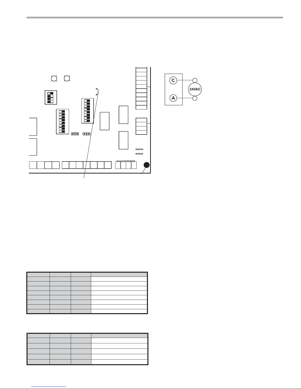
Low Water Temperature Cutout Selection - The DXM2
control allows the fi eld selection of low water (or waterantifreeze solution) temperature limit by clipping jumper
JW3, which changes the sensing temperature associated
with thermistor LT1. Note that the LT1 thermistor is
located on the refrigerant line between the coaxial heat
exchanger and expansion device (TXV). Therefore, LT1 is
sensing refrigerant temperature, not water temperature,
which is a better indication of how water fl ow rate/
temperature is affecting the refrigeration circuit.
The factory setting for LT1 is for systems using water
(30°F [-1.1°C] refrigerant temperature). In low water
temperature (extended range) applications with
antifreeze (most ground loops), jumper JW3 should be
clipped as shown in Figure 17 to change the setting to
10°F [-12.2°C] refrigerant temperature, a more suitable
temperature when using an antifreeze solution. All
ClimateMaster units operating with entering water
temperatures below 60°F [15.6°C] must include the
optional water/refrigerant circuit insulation package to
prevent internal condensation.
22
ClimateMaster Water-Source Heat Pumps
Page 23
THE SMART SOLUTION FOR ENERGY EFFICIENCY
A
HP
Figure 17: LT1 Limit Setting
Fault
Status
Off On
1 2 3 4
Off On
1 2 3 4 5 6 7 8
S3
Off On
1 2 3 4 5 6 7 8
cc1
elay
S1
cc2
elay
P11
T1
AO1
Gnd
Gnd
AO2
JW3-LT1 jumper should be clipped for low temperature
(antifreeze) operation
S2
A0-1 A0-2
P10
T2 T2 T3 T3 T4 T4
Accessory Connections - A terminal paralleling the
compressor contactor coil has been provided on the DXM2
control. Terminal “A” is designed to control accessory
devices. Note: This terminal should be used only with 24
Volt signals and not line voltage. Terminal “A” is energized
with the compressor contactor.
The DXM2 controller includes two accessory relays ACC1
and ACC2. Each relay includes a normally open (NO) and
a normally closed (NC) contact. Accessory relays may be
confi gured to operate as shown in the tables below.
Accessory Relay 1 Confi guration
DIP 2.1 DIP 2.2 DIP 2.3 ACC1 Relay Option
ON ON ON Cycle with fan
OFF ON ON N/A for Residential Applications
ON OFF ON Water valve – Slow opening
ON ON OFF Outside air damper
OFF ON OFF ClimaDry option – Dehumidistat
OFF OFF OFF ClimaDry option – Humidistat
OFF OFF ON N/A for Residential Applications
ON OFF OFF N/A for Residential Applications
All other DIP combinations are invalid
Accessory Relay 2 Confi guration
DIP 2.4 DIP 2.5 DIP 2.6 ACC2 Relay Option
ON ON ON
OFF ON ON
ON OFF ON
OFF OFF ON
ON ON OFF
All other DIP combinations are invalid
N/A for Residential Applications
JW3
12
RV
T5
Relay
Comp
Relay
P9
T5
T6 T6
1
4
24Vdc
CCG
CC
CCH
Relay
DXM2 PCB
Cycle with compressor
Water valve – Slow opening
Humidifi er
Outside air damper
climatemaster.com
LP
LP
LT1
LT1
LT2
LT2
RV
RV
CO
CO
P7
EH1
EH2
P6
Tranquility
®
22 (TY) Series
Rev.: 12/17/14
Electrical - Low Voltage Wiring
Figure 18: Accessory Wiring
P2 Terminal Strip
Typical
Wate r
Valve
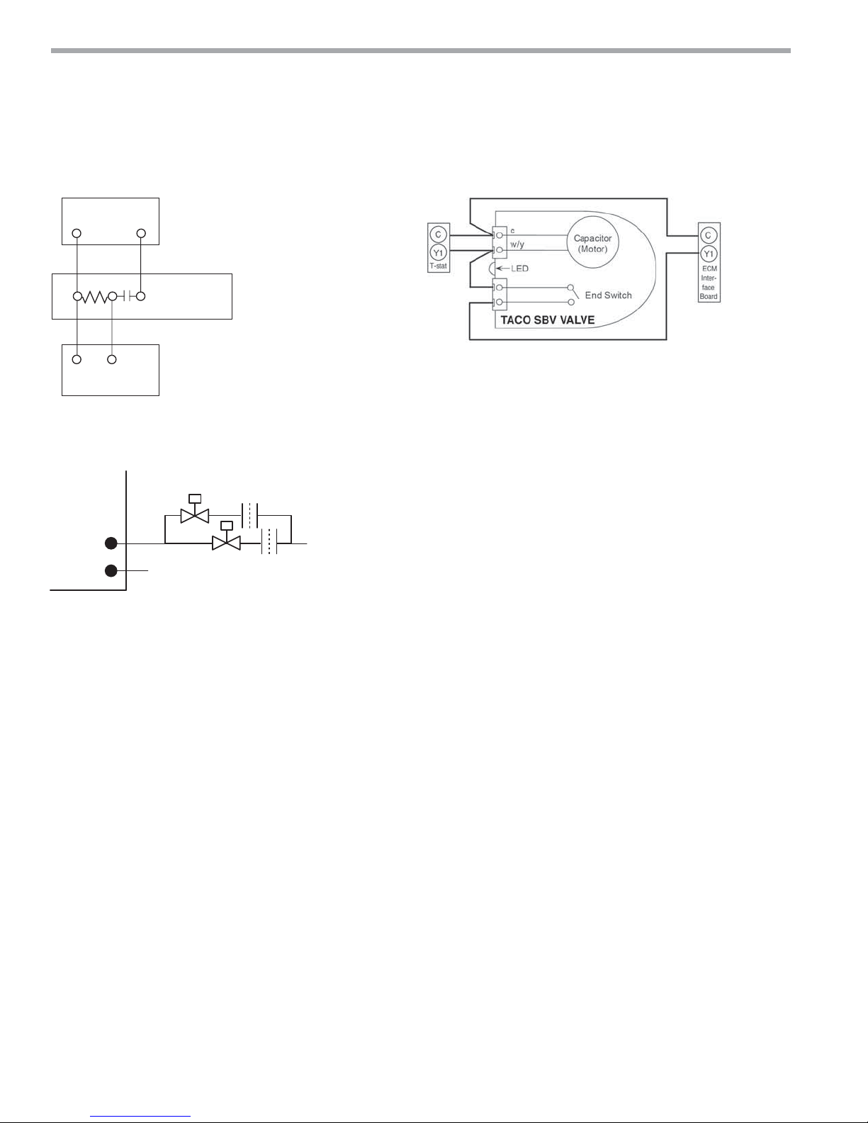
Water Solenoid Valves - An external solenoid valve(s)
should be used on ground water installations to shut off
fl ow to the unit when the compressor is not operating.
A slow closing valve may be required to help reduce
water hammer. Figure 18 shows typical wiring for a 24VAC
external solenoid valve. Figures 19 and 20 illustrate
typical slow closing water control valve wiring for Taco
500 series (ClimateMaster P/N AVM) and Taco SBV
series valves. Slow closing valves take approximately
60 seconds to open (very little water will fl ow before 45
seconds). Once fully open, an end switch allows the
compressor to be energized. Only relay or triac based
electronic thermostats should be used with slow closing
valves. When wired as shown, the slow closing valve will
operate properly with the following notations:
1. The valve will remain open during a unit lockout.
2. The valve will draw approximately 25-35 VA through
the “Y” signal of the thermostat.
Note: This valve can overheat the anticipator of an
electromechanical thermostat. Therefore, only relay or
triac based thermostats should be used.
Two-stage Units
Tranquility® 22
two parallel valves for ground water applications to limit
water use during fi rst stage operation. For example, at 1.5
gpm/ton [2.0 l/m per kW], a TY048 unit requires 6 gpm [23
l/m] for full load (2nd stage) operation, but only 4 gpm [15
l/m] during 1st stage operation. Since the unit will operate
on fi rst stage 80-90% of the time, signifi cant water savings
can be realized by using two parallel solenoid valves with two
fl ow regulators. In the example above, stage one solenoid
would be installed with a 4 gpm [15 l/m] fl ow regulator on
the outlet, while stage two would utilize a 2 gpm [8 l/m] fl ow
regulator. When stage one is operating, the second solenoid
valve will be closed. When stage two is operating, both
valves will be open, allowing full load fl ow rate.
Figure 21 illustrates piping for two-stage solenoid valves.
Review fi gures 18-20 for wiring of stage one valve. Stage
two valve should be wired between terminal “Y2” and
terminal “C.” NOTE: When EWT is below 50°F [10°C], 2
gpm per ton (2.6 l/m per kW) is required.
(TY) two-stage units should be designed with
23
Page 24
CLIMATEMASTER WATER-SOURCE HEAT PUMPS
Tranquility
Rev.: 12/17/14
®
22 (TY) Series
Electrical - Low Voltage Wiring for Units Using External Motorized Water Valve
Water Valve Wiring
Figure 19: AVM Valve Wiring Figure 20: Taco SBV Valve Wiring
C
1
Heater Switch
C
Thermostat
Figure 21: Two-Stage Piping
Y1
2
3
Taco Valve
AVM
Y1
Solenoid
Valve
Flow
Regulator
OUT
IN
Stage 2
Stage 1
From Water Source
NOTE: Shut-off valves, strainers and
other required components not shown.
To Discharge
24
ClimateMaster Water-Source Heat Pumps
Page 25
THE SMART SOLUTION FOR ENERGY EFFICIENCY
Thermostat Installation - The thermostat should be
located on an interior wall in a larger room, away from
supply duct drafts. DO NOT locate the thermostat in
areas subject to sunlight, drafts or on external walls.
The wire access hole behind the thermostat may in
certain cases need to be sealed to prevent erroneous
temperature measurement. Position the thermostat
back plate against the wall so that it appears level and
so the thermostat wires protrude through the middle
Figure 22a: Conventional 3 Heat / 2 Cool
Thermostat Connection to DXM2 Control
Thermostat
Compressor
Compressor Stage 2
Auxiliary Heat
Dehumidification
Reversing Valve
Fan
24Vac Hot
24Vac Common
Fault LED
Y1
Y2
W
DH
O
G
R
C
L
DXM2
Board
Y1
Y2
W
H
O
G
R
C
AL1
Tranquility
®
22 (TY) Series
Rev.: 12/17/14
Electrical - Thermostat Wiring
of the back plate. Mark the position of the back plate
mounting holes and drill holes with a 3/16” (5mm) bit.
Install supplied anchors and secure plate to the wall.
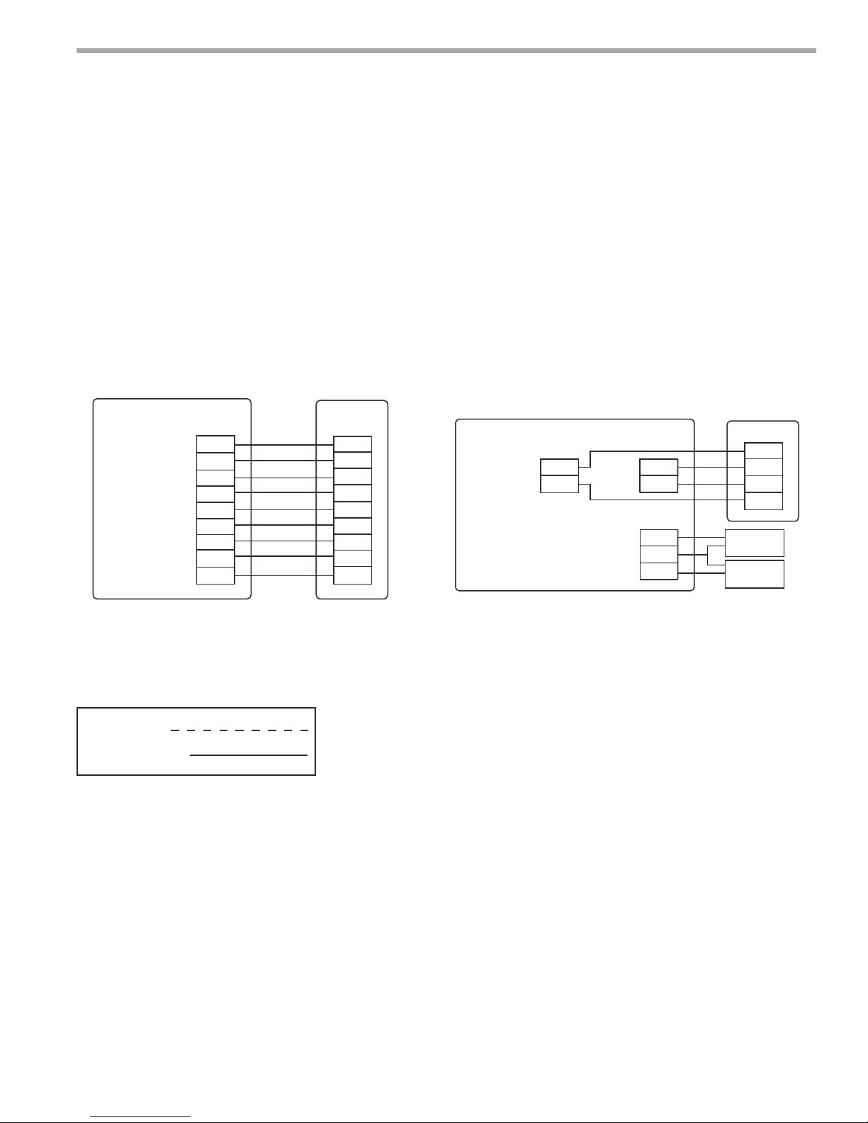
Thermostat wire must be 18 AWG wire. Representative
thermostat wiring is shown in Figures 22a-b however,
actual wiring connections should be determined from the
thermostat IOM and or unit wiring diagram. Practically
any heat pump thermostat will work with ClimateMaster
units, provided it has the correct number of heating and
cooling stages.
Figure 22b: Communicating Thermostat Connection
to
DXM2 Control
iGate™ Thermostat
24Vac Common
24Vac Hot
ATC32U**
C
R
Comm +
Comm -
A+
B-
OD
GND
ID
DXM2
Gnd
A+
B-
24V
Outdoor
Sensor
(Optiona)
Remote Indoor
Sensor
(Optiona)
Notes:
1) ECM automatic dehumidification mode operates with dehumidification airflows
in the cooling mode when the dehumidification output from thermostat is active.
Normal heating and cooling airflows are not affected.
2) DXM2 board DIP switch S2-7 must be in the auto dehumidification mode for
automatic dehumidification
3) DH connection not possible with units with internal pump. Use ATC32U**.
4) Only use ATC Communicating Thermostat when using Humidifier (H Input) with
units with internal flow controller.
Field Wiring
Factory Wiring
climatemaster.com
25
Page 26
CLIMATEMASTER WATER-SOURCE HEAT PUMPS
Tranquility
Rev.: 12/17/14
®
22 (TY) Series
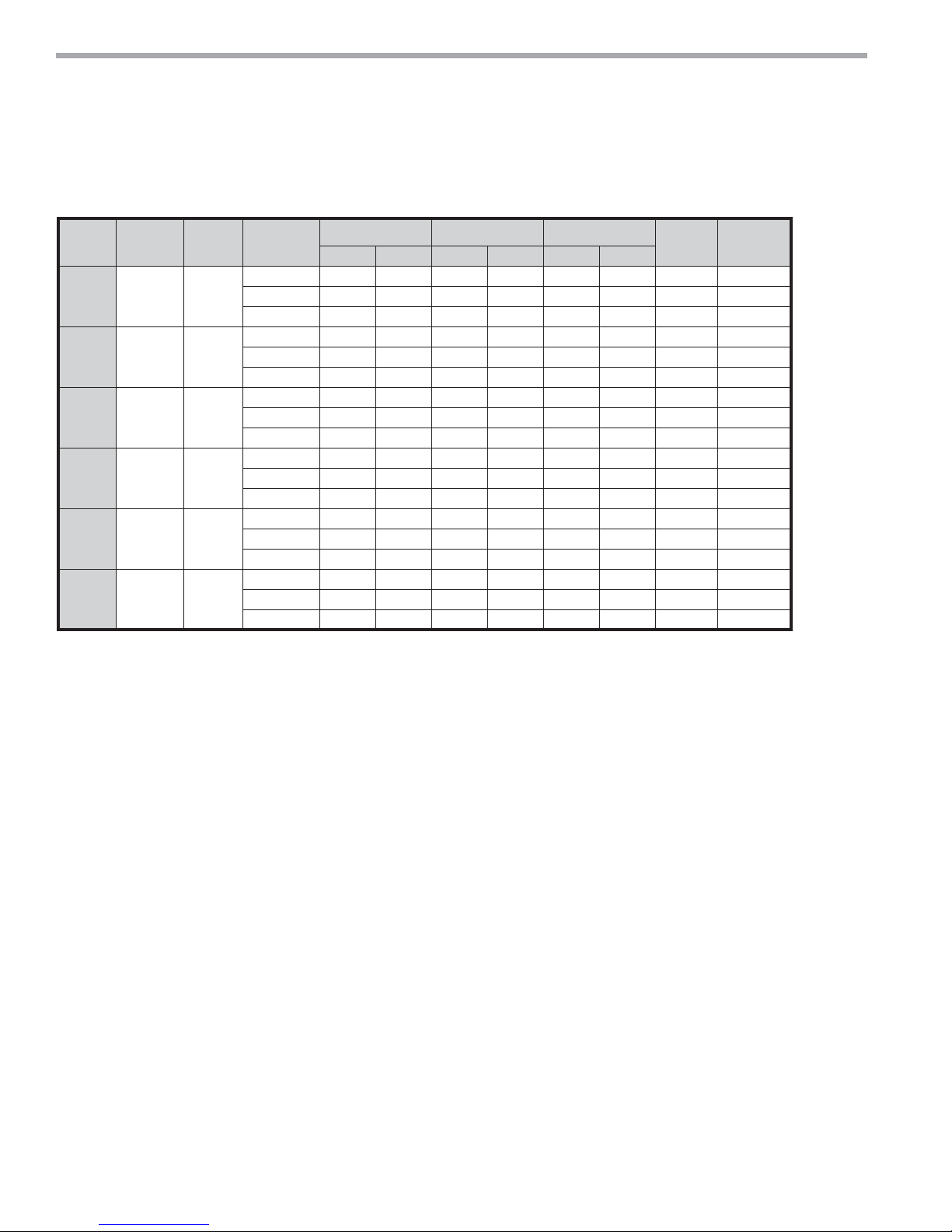
Blower Performance Data
TY Standard Unit - No Reheat
Model
024 0.75 1/2
030 0.5 1/2
036 0.6 1/2
042 0.6 3/4
048 0.75 3/4
060 0.75 1
Max ESP
(in wg)
Fan
Motor
(hp)
Range
Default 750 575 650 500 750 575 350 750
Maximum 850 650 800 600 850 850 850 850
Minimum 600 450 600 450 600 450 300 650
Default 950 650 800 575 950 650 450 950
Maximum 1100 750 1000 700 1100 1100 1100 1100
Minimum 750 525 750 525 750 525 375 750
Default 1125 750 975 650 1125 750 525 1125
Maximum 1250 950 1200 800 1250 1250 1250 1250
Minimum 900 600 900 600 900 600 450 900
Default 1300 925 1125 825 1300 925 600 1300
Maximum 1475 1100 1400 1000 1475 1475 1475 1475
Minimum 1050 750 1050 750 1050 750 525 1050
Default 1500 1125 1300 975 1500 1125 700 1500
Maximum 1700 1300 1600 1200 1700 1700 1700 1700
Minimum 1200 900 1200 900 1200 900 600 1350
Default 1875 1500 1625 1300 1875 1500 875 1875
Maximum 2100 1700 2000 1600 2100 2100 2100 2100
Minimum 1500 1200 1500 1200 1500 1200 750 1500
Cooling Mode Dehumid Mode Heating Mode
Stg 2 Stg 1 Stg 2 Stg 1 Stg 2 Stg 1
Fan Only
Mode
Aux Emerg
Mode
Airfl ow is controlled within 5% up to the Max ESP shown with wet coil.
Performance shown is with wet coil and factory air fi lters.
26
ClimateMaster Water-Source Heat Pumps
Page 27

THE SMART SOLUTION FOR ENERGY EFFICIENCY
The ECM fan is controlled directly by the DXM2 control
board that converts thermostat inputs and CFM settings
to signals used by the ECM motor controller. To take full
advantage of the ECM motor features, a communicating
multi-stage thermostat should be used (ATC32U**).
The DXM2 control maintains a selectable operating
airfl ow [CFM] for each heat pump operating mode. For
each operating mode there are maximum and minimum
airfl ow limits. See the ECM Blower Performance tables
for the maximum, minimum, and default operating
airfl ows.
Airfl ow levels are selected using the confi guration menus
of a communicating thermostat (ATC32U**) or diagnostic
tool (ACDU**). The confi guration menus allow the
installer to independently select and adjust the operating
airfl ow for each of the operating modes. Air fl ow can be
selected in 25 CFM increments within the minimum and
maximum limits shown in the ECM Blower Performance
Table. The blower operating modes include:
• First Stage Cooling (Y1 & O)
• Second Stage Cooling (Y1, Y2, & O)
• First Stage Cooling in Dehumidification Mode
(Y1, O, & Dehumid)
• Second Stage Cooling in Dehumidification Mode
(Y1, Y2, O, & Dehumid)
• First Stage Heating (Y1)
• Second Stage Heating (Y1 & Y2)
• Third Stage (Auxiliary) Heating (Y1, Y2, & W)
• Emergency Heating (W with no Y1 or Y2)
• Fan (G with no Y1, Y2, or W)
Tranquility
®
22 (TY) Series
Rev.: 12/17/14
ECM Blower Control
The ramp down feature is eliminated during an ESD
(Emergency Shut Down) situation. When the DXM2
ESD input is activated, the blower and all other control
outputs are immediately de-activated.
The ramp down feature (also known as the heating or
cooling “Off Delay”) is fi eld selectable by the installer.
The allowable range is 0 to 255 seconds.
Special Note for AHRI Testing:
To achieve rated airfl ow for AHRI testing purposes, it is
necessary to change the CFM settings to rated airfl ow.
It is highly recommended that ATC32U** or ACDU**
be used to set dehumidifi cation mode electronically.
Dehumidifi cation can NOT be selected when using a
non-communicating thermostat with a vFlow™ unit with
Internal Flow Controller (pump). For dehumidifi cation
settings on other units using the non-communicating
stat, refer to DXM2 AOM (part #97B0003N15).
The ECM motor includes “soft start” and “ramp down”
features. The soft start feature is a gentle increase of
motor rpm at blower start up. This creates a much quieter
blower start cycle.
The ramp down feature allows the blower to slowly
decrease rpm to a full stop at the end of each blower
cycle. This creates a much quieter end to each blower
cycle and adds overall unit effi ciency.
climatemaster.com
27
Page 28
CLIMATEMASTER WATER-SOURCE HEAT PUMPS
Tranquility
Rev.: 12/17/14
®
22 (TY) Series
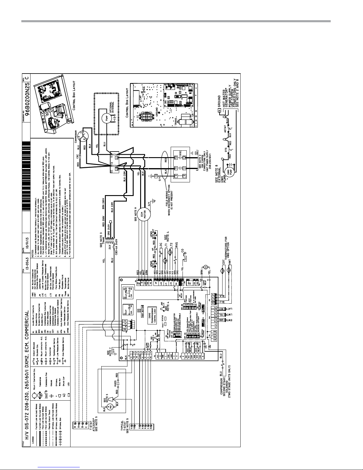
Typical Wiring Diagram - Single Phase Units
28
ClimateMaster Water-Source Heat Pumps
Page 29
THE SMART SOLUTION FOR ENERGY EFFICIENCY
Tranquility
®
22 (TY) Series
Rev.: 12/17/14
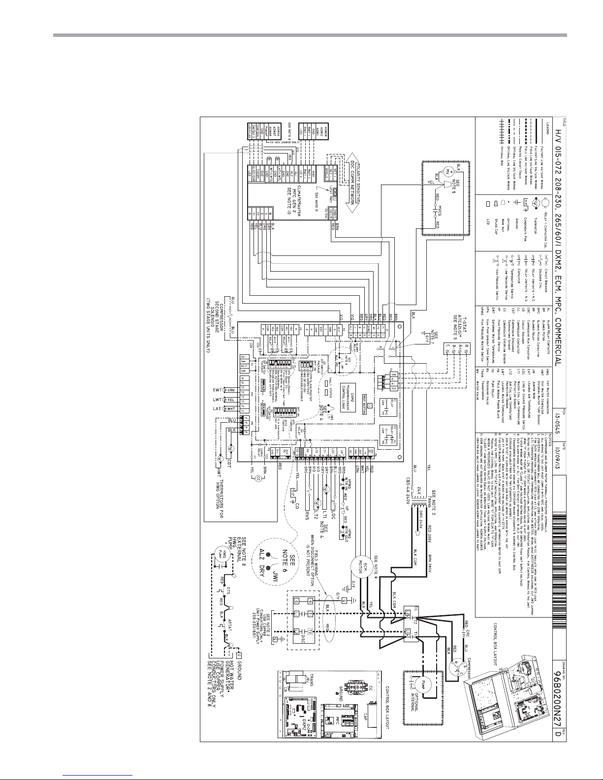
Typical Wiring Diagram - Single Phase Unit with MPC Controller
climatemaster.com
29
Page 30
CLIMATEMASTER WATER-SOURCE HEAT PUMPS
Tranquility
Rev.: 12/17/14
®
22 (TY) Series
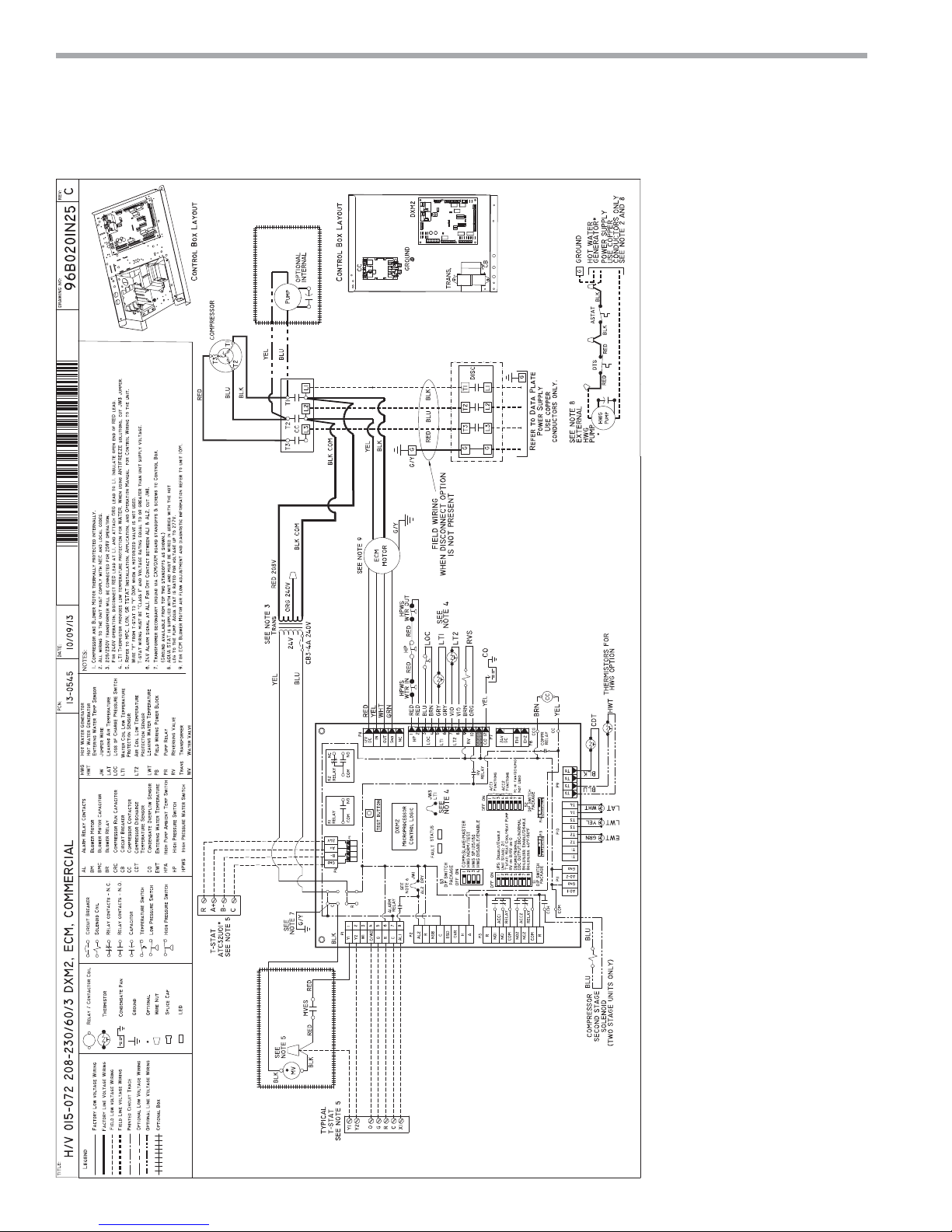
Typical Wiring Diagram - Three Phase Units
30
ClimateMaster Water-Source Heat Pumps
Page 31

THE SMART SOLUTION FOR ENERGY EFFICIENCY
DXM2 Control - For detailed control information, see
DXM2 Application, Operation and Maintenance (AOM)
manual (part # 97B0003N15).
Field Selectable Inputs - Test mode: Test mode allows
the service technician to check the operation of the
control in a timely manner. By momentarily pressing the
TEST pushbutton, the DXM2 control enters a 20 minute
test mode period in which all time delays are sped up
15 times. Upon entering test mode, the status LED
display will change, either fl ashing rapidly to indicate the
control is in the test mode, or displaying a numeric fl ash
code representing the current airfl ow if an ECM blower
is connected and operating. For diagnostic ease at
conventional thermostats, the alarm relay will also cycle
during test mode. The alarm relay will cycle on and off
similar to the fault LED to indicate a code representing
the last fault, at the thermostat. Test mode can be exited
by pressing the TEST pushbutton for 3 seconds.
Retry Mode – If the control is attempting a retry of a
fault, the fault LED will slow fl ash (slow fl ash = one fl ash
every 2 seconds) to indicate the control is in the process
of retrying.
Field Confi guration Options – Note: In the following
fi eld confi guration options, jumper wires should be
clipped ONLY when power is removed from the DXM2
control.
Water coil low temperature limit setting: Jumper 3 (JW3LT1 Low Temp) provides fi eld selection of temperature
limit setting for LT1 of 30°F or 10°F [-1°F or -12°C]
(refrigerant temperature).
Not Clipped = 30°F [-1°C]. Clipped = 10°F [-12°C].
Alarm relay setting: Jumper 1 (JW1-AL2 Dry) provides
fi eld selection of the alarm relay terminal AL2 to
be jumpered to 24VAC or to be a dry contact (no
connection).
Not Clipped = AL2 connected to R. Clipped = AL2 dry
contact (no connection).
DIP Switches – Note: In the following fi eld confi guration
options, DIP switches should only be changed when
power is removed from the DXM2 control.
DIP Package #1 (S1) – DIP Package #1 has 8 switches
and provides the following setup selections:
1.1 - Unit Performance Sentinel (UPS) disable: DIP Switch
1.1 provides fi eld selection to disable the UPS feature.
On = Enabled. Off = Disabled.
1.2 - Compressor relay staging operation: DIP 1.2
provides selection of compressor relay staging operation.
The compressor relay can be selected to turn on with
a stage 1 or stage 2 call from the thermostat. This
is used with dual stage units (2 compressors where
2 DXM2 controls are being used) or with master/
slave applications. In master/slave applications,
each compressor and fan will stage according to
its appropriate DIP 1.2 setting. If set to stage 2, the
compressor will have a 3 second on-delay before
energizing during a Stage 2 demand. Also, if set for
stage 2, the alarm relay will NOT cycle during test mode.
On = Stage 1. Off = Stage 2.
1.3 - Thermostat type (heat pump or heat/cool): DIP 1.3
provides selection of thermostat type. Heat pump or
heat/cool thermostats can be selected. When in heat/
cool mode, Y1 is the input call for cooling stage 1; Y2 is
the input call for cooling stage 2; W1 is the input call for
heating stage 1; and O/W2 is the input call for heating
stage 2. In heat pump mode, Y1 is the input call for
compressor stage 1; Y2 is the input call for compressor
stage 2; W1 is the input call for heating stage 3 or
emergency heat; and O/W2 is the input call for reversing
valve (heating or cooling, depending upon DIP 1.4).
On = Heat Pump. Off = Heat/Cool.
1.4 - Thermostat type (O/B): DIP 1.4 provides selection of
thermostat type for reversing valve activation. Heat pump
thermostats with “O” output (reversing valve energized
for cooling) or “B” output (reversing valve energized for
heating) can be selected with DIP 1.4.
On = HP stat with “O” output for cooling. Off = HP stat
with “B” output for heating.
1.5 - Dehumidifi cation mode: DIP 1.5 provides
selection of normal or dehumidifi cation fan mode. In
dehumidifi cation mode, the fan speed relay will remain
off during cooling stage 2. In normal mode, the fan
speed relay will turn on during cooling stage 2.
On = Normal fan mode. Off = Dehumidifi cation mode.
1.6 – DDC output at EH2: DIP 1.6 provides selection for
DDC operation. If set to “DDC Output at EH2,” the EH2
terminal will continuously output the last fault code of
the controller. If set to “EH2 normal,” EH2 will operate as
standard electric heat output.
On = EH2 Normal. Off = DDC Output at EH2.
1.7– Boilerless operation: DIP 1.7 provides selection of
boilerless operation. In boilerless mode, the compressor
is only used for heating when LT1 is above the
temperature specifi ed by the setting of DIP 1.8. Below
DIP 1.8 setting, the compressor is not used and the
control goes into emergency heat mode, staging on EH1
and EH2 to provide heating.
climatemaster.com
Tranquility
®
22 (TY) Series
Rev.: 12/17/14
DXM2 Controls
31
Page 32
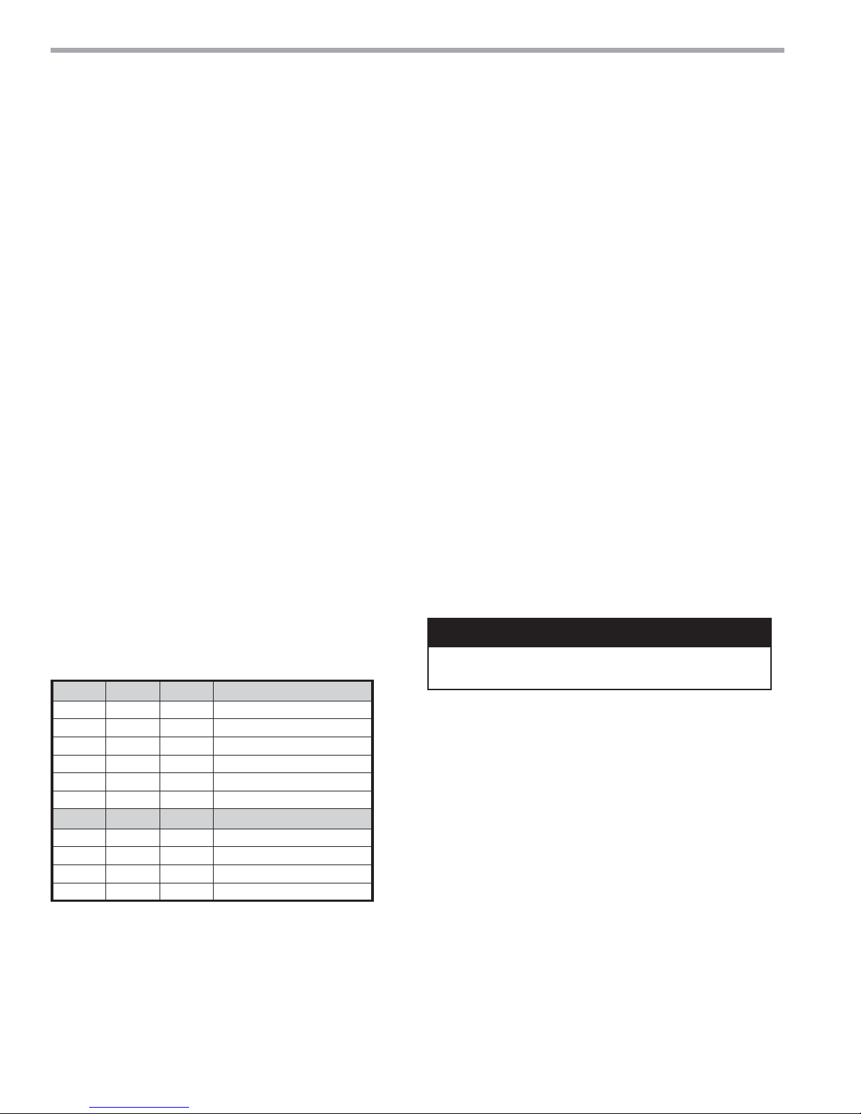
CLIMATEMASTER WATER-SOURCE HEAT PUMPS
(
Tranquility
Rev.: 12/17/14
®
22 (TY) Series
DXM2 Controls
On = normal. Off = Boilerless operation.
1.8 – Boilerless changeover temperature: DIP 1.8
provides selection of boilerless changeover temperature
setpoint. Note that the LT1 thermistor is sensing
refrigerant temperature between the coaxial heat
exchanger and the expansion device (TXV). Therefore,
the 50°F [10°C] setting is not 50°F [10°C] water, but
approximately 60°F [16°C] EWT.
On = 50°F [10°C]. Off = 40°F [16°C].
DIP Package #2 (S2) – A combination of dip switches
2.1, 2.2, 2.3, and 2.4, 2.5, 2.6 deliver confi guration of
ACC1 and ACC2 relay options respectively. See Table 7a
for description and functionality.
2.7 – Auto dehumidifi cation fan mode or high fan mode:
DIP 2.7 provides selection of auto dehumidifi cation fan
mode or high fan mode. In auto dehumidifi cation mode,
the fan speed relay will remain off during cooling stage 2
IF the H input is active. In high fan mode, the fan enable
and fan speed relays will turn on when the H input is
active.
On = Auto dehumidifi cation mode (default). Off = High
fan mode.
2.8 – Special factory selection: DIP 2.8 provides special
factory selection. Normal position is “On”. Do not
change selection unless instructed to do so by the
factory.
Table 7a: Accessory DIP Switch Settings
DIP 2.1 DIP 2.2 DIP 2.3 ACC1 Relay Option
On On On Cycle with fan
Off On On Digital NSB
On Off On Water Valve - slow opening
On On Off OAD
Off Off Off Reheat Option - Humidistat
Off On Off Reheat Option - Dehumidistat
DIP 2.4 DIP 2.5 DIP 2.6 ACC2 Relay Option
On On On Cycle with compressor
Off On On Digital NSB
On Off On Water Valve - slow opening
On On Off OAD
SSV[OLY+07JVTIPUH[PVUZHYLPU]HSPK
DIP Package #3 (S3)
– DIP Package #3 has 4 switches and provides the
following setup and operating selections:
3.1 – Communications confi guration: DIP 3.1 provides
selection of the DXM2 operation in a communicating
system. The DXM2 may operate as the Master of certain
network confi gurations. In most confi gurations the
DXM2 will operate as a master device.
On = Communicating Master device (default). Off =
communicating Slave device.
3.2 – HWG Test Mode: DIP 3.2 provides forced operation
of the HWG pump output, activating the HWG pump
output for up to fi ve minutes.
On = HWG test mode. Off = Normal HWG mode
(default).
3.3 – HWG Temperature: DIP 3.3 provides the selection
of the HWG operating setpoint.
On = 150°F [66°C]. Off = 125°F [52°C] (default).
3.4 – HWG Status: DIP 3.4 provides HWG operation
control.
On = HWG mode enabled. Off = HWG mode disabled
(default).
CAUTION!
CAUTION! Do not restart units without inspection and
remedy of faulting condition. Equipment damage may occur.
32
ClimateMaster Water-Source Heat Pumps
Page 33
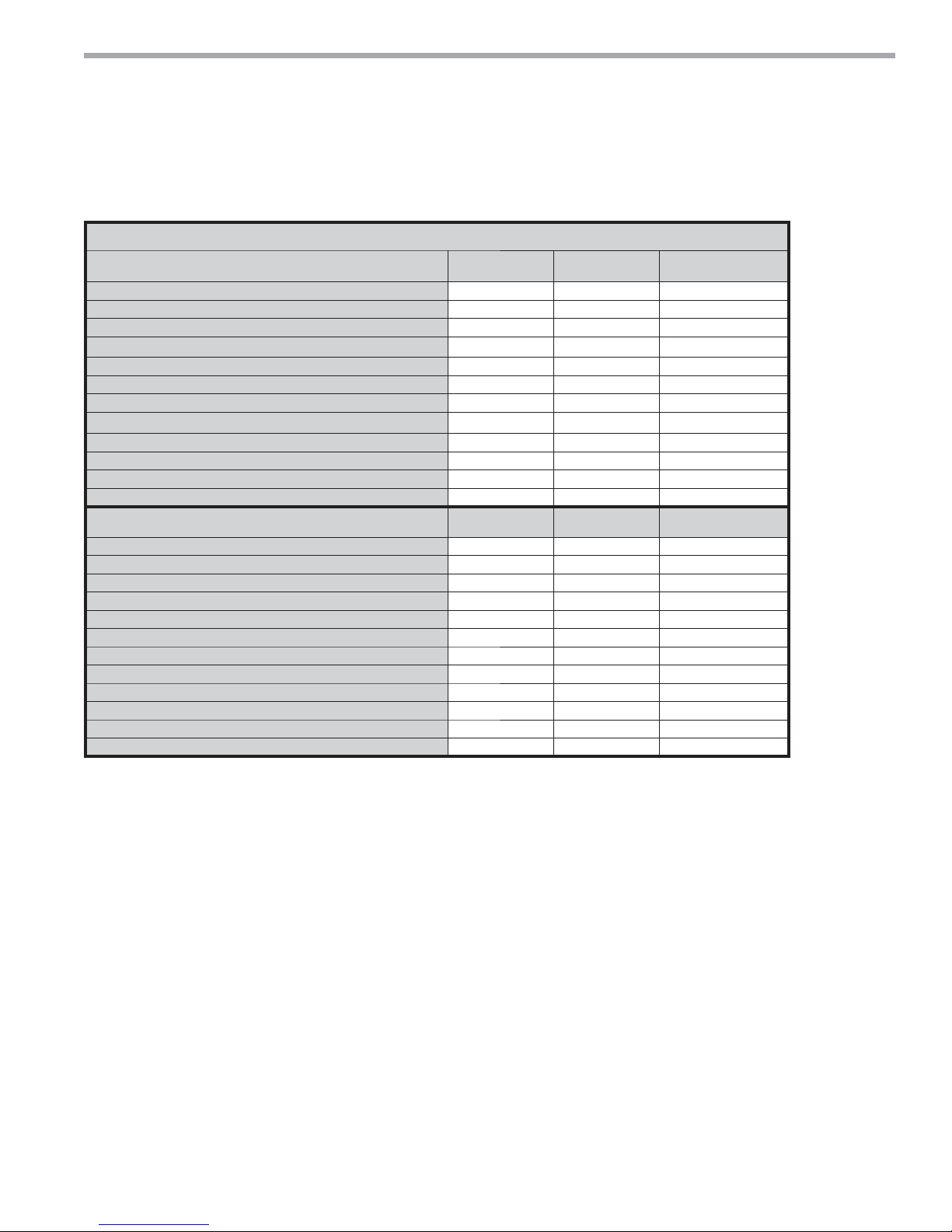
THE SMART SOLUTION FOR ENERGY EFFICIENCY
Table 7b: LED and Alarm Relay Output Table
DMX2 CONTROLLER FAULT CODES
DMX2 Fault and Status LED Operation
with Test Mode Not Active
DXM2 Is Non-Functional Off Off Open
Normal Operation - No Active Communications On On Open
Normal Operation - With Active Communications Very Slow Flash ON Open
Control Is Currently In Fault Retry Mode Slow Flash - Open
Control Is Currently Locked Out Fast Flash - Closed
Control Is Currently In An Over/ Under Voltage Condition Slow Flash - Open (Closed After 15 min)
Hot Water Mode Active - Slow Flash Open
(NSB) Night Setback Condition Recognized - Flashing Code 2 -
(ESD) Emergency Shutdown Condition Recognized - Flashing Code 3 -
Invalid Thermostat Input Combination - Flashing Code 4 -
High Hot Water Temperature Lockout Active - Flashing Code 5 -
Hot Water Mode Sensor Fault Active - Flashing Code 6 -
DMX2 Fault LED and Status Operation
with Test Mode Active
No Fault Since Power Up In Memory Flashing Code 1 - Cycling Code 1
High Pressure Fault In Memory Flashing Code 2 - Cycling Code 2
Low Pressure Fault In Memory Flashing Code 3 - Cycling Code 3
Low Temperature Protection 1 In Fault Memory Flashing Code 4 - Cycling Code 4
Low Temperature Protection 2 In Fault Memory Flashing Code 5 - Cycling Code 5
Condensate Overfl ow Fault In Memory Flashing Code 6 - Cycling Code 6
Over/Under Voltage Shutdown In Memory Flashing Code 7 - Cycling Code 7
UPS Warning In Memory Flashing Code 8 - Cycling Code 8
UPT Fault In Memory Flashing Code 9 - Cycling Code 9
ECM Air Flow Fault In Memory Flashing Code 10 - Cycling Code 10
Test Mode Active With No ECM Connected Or Operating - Fast Flash -
Test Mode Active With ECM Operating - Flashing ECM Airfl ow -
Fault LED
(Red)
Fault LED
(Red)
Tranquility
Status LED
(Green)
Status LED
(Green)
®
22 (TY) Series
DXM2 Controls
Alarm Relay
Alarm Relay
Rev.: 12/17/14
- Fast Flash = 2 fl ashes every 1 second.
- Slow Flash = 1 fl ash every 2 seconds.
- Very Slow Flash = 1 fl ash every 5 seconds.
- Numeric Codes = On pulse 1/3 second; Off pulse 1/3 second followed by a 10 second delay.
- ECM Airfl ow = 1 fl ash per 100 CFM; On pulse 1/3 second followed by a 10 second delay.
- Alarm Relay Open = alarm signal off; Alarm Relay Closed = alarm signal on.
climatemaster.com
33
Page 34
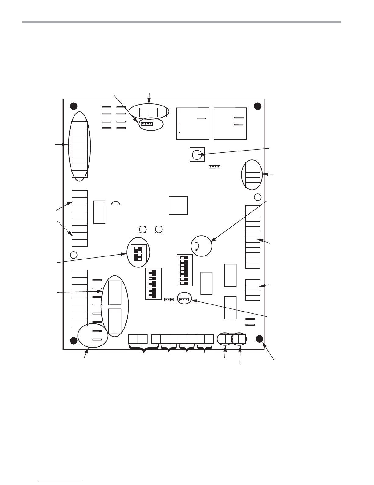
CLIMATEMASTER WATER-SOURCE HEAT PUMPS
Tranquility
Rev.: 12/17/14
®
22 (TY) Series
DXM2 Layout and Connections
Service tool
connection
C
Conventional
stat connection
Cabinet
temperature
sensor
(with variable
speed pump)
Communications
and HWG
Settings
Accessory
relays refer
to DXM2 AOM
for configuration
P1
Y1
Y2
W
O
G
R
C
AL1
P2
AL2
R
NSB
C
ESD
OVR
H
A
P3
R
NO1
NC1
COM1
NO2
NC2
COM2
R
COH
COM
Alarm
Relay
R
JW1
Acc1
Relay
sU yrotcaF
e
Acc2
Relay
Communicating
stat connection
Gnd
B-
A+ 24V
P5
Fault
Status
Off On
1 2 3 4
S3
Off On
1 2 3 4 5 6 7 8
S1
P11
T1
Gnd
AO2
P4
(240Vac)
N.O.
Com
Fan Enable
Test
Micro
U1
Off On
S2
A0-1 A0-2
JW3
1 2 3 4 5 6 7 8
CCH
Relay
P10
T2 T2 T3 T3 T4 T4
(240Vac)
Fan Speed
P12
RV
Relay
Comp
Relay
P9
T5
T5
N.C.
N.O.
12
T6 T6
1
1
4
P8
12V
IN
OUT
Gnd
NC
HP
HP
LP
LP
LT1
LT1
LT2
LT2
RV
RV
CO
CO
P7
24Vdc
EH1
EH2
P6
CCG
CC
Test Button
to Speed up
Time Delays
ECM Motor
Connection
Water Coil
Low Temp
Limit Setting.
JWT-LT1 jumper
should be clipped
for low temp
(antifreeze)
operation
Factory low
voltage molex
connection for
unit harness
Electric heat
connection
Configure
modulating valve
or variable
speed pump
24V to compressor
second-stage solenoid
for Y2/full
load capacity
34
ClimateMaster Water-Source Heat Pumps
Variable
speed pump
water temp
Entering
water temp
air temp
Leaving
Leaving
Entering Hot water
Compressor Discharge
Temperature
Use 4 mounting screws
temperature
#6 sheet metal screw
1” long
Page 35
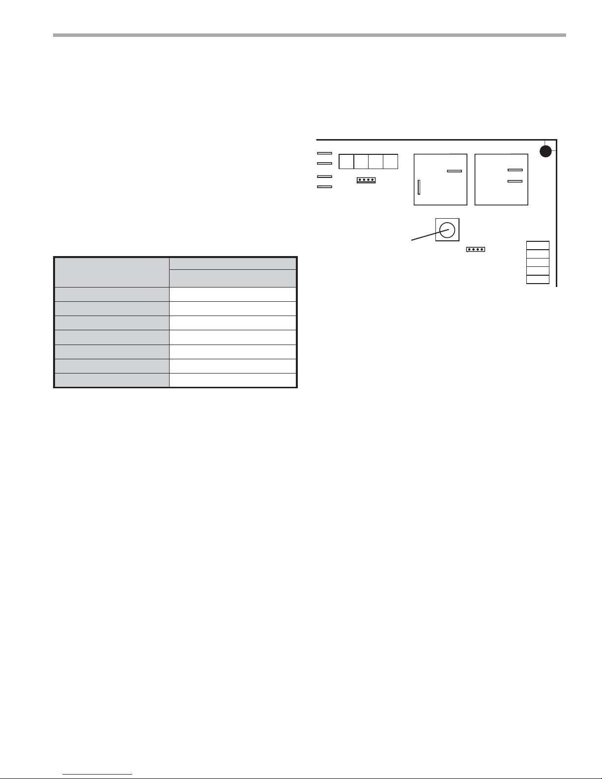
THE SMART SOLUTION FOR ENERGY EFFICIENCY
DXM2 Control Start-up Operation – The control will not
operate until all inputs and safety controls are checked
for normal conditions. The compressor will have a 5
minute anti-short cycle delay at power-up. The fi rst time
after power-up that there is a call for compressor, the
compressor will follow a 5 to 80 second random start delay.
After the random start delay and anti-short cycle delay,
the compressor relay will be energized. On all subsequent
compressor calls, the random start delay is omitted.
Table 7c: Unit Operation
Conventional
T-stat signal
(Non-Communicating)
G Fan only
G, Y1 Stage 1 heating
G, Y1, Y2 Stage 2 heating
G, Y1, Y2, W Stage 3 heating
G, W Emergency heat
G, Y1, O Stage 1 cooling
G, Y1, Y2, O Stage 2 cooling
1
Stage 1 = 1st stage compressor, 1st stage fan operation
Stage 2 = 2nd stage compressor, 2nd stage fan operation
Stage 3 = 2nd stage compressor, auxiliary electric heat, 3rd stage fan operation
2
Stage 1 = 1st stage compressor, 1st stage fan operation, reversing valve
Stage 2 = 2nd stage compressor, 2nd stage fan operation, reversing valve
Unit
ECM fan
1
1
1
2
2
Tranquility
Figure 26b: Test Mode Button
Gnd
B-
Pust test button to enter Test
Mode and speed-up timing and
delays for 20 minutes.
A+ 24V
P5
P4
(240Vac)
Com
Fan Enable
Test
®
22 (TY) Series
Rev.: 12/17/14
DXM2 Controls
(240Vac)
N.O.
N.C.
N.O.
Fan Speed
P12
P8
12V
IN
OUT
Gnd
NC
climatemaster.com
35
Page 36
CLIMATEMASTER WATER-SOURCE HEAT PUMPS
Tranquility
®
22 (TY) Series
Rev.: 12/17/14
DXM2 Controls
Table 8: Nominal Resistance at Various Temperatures
Temp (ºC) Temp (ºF)
-17.8 0.0 85.34 55 131.0 2.99
-17.5 0.5 84.00 56 132.8 2.88
-16.9 1.5 81.38 57 134.6 2.77
-12 10.4 61.70 58 136.4 2.67
-11 12.2 58.40 59 138.2 2.58
-10 14.0 55.30 60 140.0 2.49
-9 15.8 52.38 61 141.8 2.40
-8 17.6 49.64 62 143.6 2.32
-7 19.4 47.05 63 145.4 2.23
-6 21.2 44.61 64 147.2 2.16
-5 23.0 42.32 65 149.0 2.08
-4 24.8 40.15 66 150.8 2.01
-3 26.6 38.11 67 152.6 1.94
-2 28.4 36.18 68 154.4 1.88
-1 30.2 34.37 69 156.2 1.81
0 32.0 32.65 70 158.0 1.75
1 33.8 31.03 71 159.8 1.69
2 35.6 29.50 72 161.6 1.64
3 37.4 28.05 73 163.4 1.58
4 39.2 26.69 74 165.2 1.53
5 41.0 25.39 75 167.0 1.48
6 42.8 24.17 76 168.8 1.43
7 44.6 23.02 77 170.6 1.39
8 46.4 21.92 78 172.4 1.34
9 48.2 20.88 79 174.2 1.30
10 50.0 19.90 80 176.0 1.26
11 51.8 18.97 81 177.8 1.22
12 53.6 18.09 82 179.6 1.18
13 55.4 17.26 83 181.4 1.14
14 57.2 16.46 84 183.2 1.10
15 59.0 15.71 85 185.0 1.07
16 60.8 15.00 86 186.8 1.04
17 62.6 14.32 87 188.6 1.01
18 64.4 13.68 88 190.4 0.97
19 66.2 13.07 89 192.2 0.94
20 68.0 12.49 90 194.0 0.92
21 69.8 11.94 91 195.8 0.89
22 71.6 11.42 92 197.6 0.86
23 73.4 10.92 93 199.4 0.84
24 75.2 10.45 94 201.2 0.81
25 77.0 10.00 95 203.0 0.79
26 78.8 9.57 96 204.8 0.76
27 80.6 9.16 97 206.6 0.74
28 82.4 8.78 98 208.4 0.72
29 84.2 8.41 99 210.2 0.70
30 86.0 8.06 100 212.0 0.68
31 87.8 7.72 101 213.8 0.66
32 89.6 7.40 102 215.6 0.64
33 91.4 7.10 103 217.4 0.62
34 93.2 6.81 104 219.2 0.60
35 95.0 6.53 105 221.0 0.59
36 96.8 6.27 106 222.8 0.57
37 98.6 6.01 107 224.6 0.55
38 100.4 5.77 108 226.4 0.54
39 102.2 5.54 109 228.2 0.52
40 104.0 5.33 110 230.0 0.51
41 105.8 5.12 111 231.8 0.50
42 107.6 4.92 112 233.6 0.48
43 109.4 4.72 113 235.4 0.47
44 111.2 4.54 114 237.2 0.46
45 113.0 4.37 115 239.0 0.44
46 114.8 4.20 116 240.8 0.43
47 116.6 4.04 117 242.6 0.42
48 118.4 3.89 118 244.4 0.41
49 120.2 3.74 119 246.2 0.40
50 122.0 3.60 120 248.0 0.39
51 123.8 3.47 121 249.8 0.38
52 125.6 3.34 122 251.6 0.37
53 127.4 3.22 123 253.4 0.36
54 129.2 3.10
Resistance
(kOhm)
Temp (ºC) Temp (ºF)
Resistance
(kOhm)
DXM2 Thermostat Details
Thermostat Compatibility – Most heat pump and heat/
cool thermostats can be used with the DXM2, as well as
ClimateMaster communicating thermostats (ATC32).
Anticipation Leakage Current – Maximum leakage
current for “Y1” is 50 mA and for “W” is 20mA. Triacs
can be used if leakage current is less than above.
Thermostats with anticipators can be used if anticipation
current is less than that specifi ed above.
Thermostat Signals -
• “Y1, Y2, W1, O” and “G” have a 1 second recognition
time when being activated or being removed.
• “R” and “C” are from the transformer.
• “AL1” and “AL2” originate from the Alarm Relay.
• “A+” and “B-” are for a communicating thermostat.
36
ClimateMaster Water-Source Heat Pumps
Page 37
THE SMART SOLUTION FOR ENERGY EFFICIENCY
Tranquility
®
22 (TY) Series
Rev.: 12/17/14
Unit Starting and Operating Conditions
Operating Limits
Environment – Units are designed for indoor installation only. Never install units in areas subject to freezing or where
humidity levels could cause cabinet condensation (such as unconditioned spaces subject to 100% outside air).
Power Supply – A voltage variation of +/– 10% of nameplate utilization voltage is acceptable.
Determination of operating limits is dependent primarily upon three factors: 1) return air temperature. 2) water
temperature, and 3) ambient temperature. When any one of these factors is at minimum or maximum levels, the
other two factors should be at normal levels to ensure proper unit operation. Extreme variations in temperature and
humidity and/or corrosive water or air will adversely affect unit performance, reliability, and service life. Consult Table
9a for operating limits.
Table 9a: Operating Limits
Operating Limits
Air Limits
Min. ambient air, DB
Rated ambient, DB
Max. ambient air, DB
Min. entering air, DB/WB
Rated entering air, DB/WB
Max. entering air, DB/WB
Water Limits
Min. entering water
Normal entering water
Max. entering water
Normal Water Flow
Cooling Heating
45ºF [7ºC]
80.6ºF [27ºC]
130ºF [54.4ºC]
65/45ºF [18/7ºC]
80.6/66.2ºF [27/19ºC]
100/75ºF [38/24ºC]
30ºF [-1.1ºC]
50 – 110ºF [10 – 43.3ºC]
120ºF [48.9ºC]
[1.6 to 3.2 l/m per kW]
TY
39ºF [4ºC]
68ºF [20ºC]
85ºF [29ºC]
50ºF [10ºC]
68ºF [20ºC]
80ºF [27ºC]
20ºF [-6.7ºC]
30-80ºF [-1.1 – 26.7ºC]
90ºF [32.2ºC]
1.5 to 3.0 gpm / ton
Operating Limits
Environment – Units are designed for indoor installation only. Never install units in areas subject to freezing or where
humidity levels could cause cabinet condensation (such as unconditioned spaces subject to 100% outside air).
Power Supply – A voltage variation of +/– 10% of nameplate utilization voltage is acceptable.
Determination of operating limits is dependent primarily upon three factors: 1) return air temperature. 2) water
temperature, and 3) ambient temperature. When any one of these factors is at minimum or maximum levels, the
other two factors should be at normal levels to ensure proper unit operation. Extreme variations in temperature and
humidity and/or corrosive water or air will adversely affect unit performance, reliability, and service life. Consult Table
9a for operating limits.
Table 9b: Starting Limits
Operating Limits
Air Limits
Min. ambient air, DB
Rated ambient, DB
Max. ambient air, DB
Min. entering air, DB/WB
Rated entering air, DB/WB
Max. entering air, DB/WB
Water Limits
Min. entering water
Normal entering water
Max. entering water
Normal Water Flow
Cooling Heating
45ºF [7ºC]
80.6ºF [27ºC]
130ºF [54.4ºC]
60/45ºF [16/7ºC]
80.6/66.2ºF [27/19ºC]
100/75ºF [38/24ºC]
30ºF [-1.1ºC]
50 – 110ºF [10 – 43.3ºC]
120ºF [48.9ºC]
TY
39ºF [4ºC]
68ºF [20ºC]
85ºF [29ºC]
50ºF [10ºC]
68ºF [20ºC]
80ºF [27ºC]
20ºF [-6.7ºC]
30-80ºF [-1.1 – 26.7ºC]
90ºF [32.2ºC]
1.5 to 3.0 gpm / ton
[1.6 to 3.2 l/m per kW]
climatemaster.com
37
Page 38

CLIMATEMASTER WATER-SOURCE HEAT PUMPS
Tranquility
Rev.: 12/17/14
®
22 (TY) Series
Piping System Cleaning and Flushing
Piping System Cleaning and Flushing - Cleaning and
fl ushing the WLHP piping system is the single most
important step to ensure proper start-up and continued
effi cient operation of the system.
Follow the instructions below to properly clean and fl ush
the system:
1. Ensure that electrical power to the unit is
disconnected.
2. Install the system with the supply hose connected
directly to the return riser valve. Use a single length of
fl exible hose.
3. Open all air vents. Fill the system with water. DO NOT
allow system to overfl ow. Bleed all air from the system.
Pressurize and check the system for leaks and repair as
appropriate.
4. Verify that all strainers are in place (ClimateMaster
recommends a strainer with a #20 stainless steel
wire mesh). Start the pumps, and systematically
check each vent to ensure that all air is bled from the
system.
5. Verify that make-up water is available. Adjust make-up
water as required to replace the air which was bled
from the system. Check and adjust the water/air level
in the expansion tank.
6. Set the boiler to raise the loop temperature to
approximately 86°F [30°C]. Open a drain at the
lowest point in the system. Adjust the make-up water
replacement rate to equal the rate of bleed.
7. Refi ll the system and add trisodium phosphate in
a proportion of approximately one pound per 150
gallons (.8 kg per 1000 l) of water (or other equivalent
approved cleaning agent). Reset the boiler to raise
the loop temperature to 100°F [38°C]. Circulate the
solution for a minimum of 8 to 24 hours. At the end
of this period, shut off the circulating pump and drain
the solution. Repeat system cleaning if desired.
8. When the cleaning process is complete, remove the
short-circuited hoses. Reconnect the hoses to the
proper supply, and return the connections to each of
the units. Refi ll the system and bleed off all air.
9. Test the system pH with litmus paper. The system
water should be in the range of pH 6.0 - 8.5 (see
table 3). Add chemicals, as appropriate to maintain
neutral pH levels.
10. When the system is successfully cleaned, fl ushed,
refi lled and bled, check the main system panels,
safety cutouts and alarms. Set the controls to properly
maintain loop temperatures.
DO NOT use “Stop Leak” or similar chemical agent in
this system. Addition of chemicals of this type to the
loop water will foul the heat exchanger and inhibit unit
operation.
Note: The manufacturer strongly recommends all
piping connections, both internal and external to the
unit, be pressure tested by an appropriate method
prior to any fi nishing of the interior space or before
access to all connections is limited. Test pressure may
not exceed the maximum allowable pressure for the
unit and all components within the water system.
The manufacturer will not be responsible or liable
for damages from water leaks due to inadequate or
lack of a pressurized leak test, or damages caused
by exceeding the maximum pressure rating during
installation.
38
ClimateMaster Water-Source Heat Pumps
Page 39
THE SMART SOLUTION FOR ENERGY EFFICIENCY
WARNING!
WARNING! Polyolester Oil, commonly known as POE oil, is
a synthetic oil used in many refrigeration systems including
those with HFC-410A refrigerant. POE oil, if it ever comes
in contact with PVC or CPVC piping, may cause failure of
the PVC/CPVC. PVC/CPVC piping should never be used
as supply or return water piping with water source heat
pump products containing HFC-410A as system failures and
property damage may result.
Unit and System Checkout
BEFORE POWERING SYSTEM, please check the following:
UNIT CHECKOUT
Balancing/shutoff valves: Ensure that all isolation
valves are open and water control valves are wired.
Line voltage and wiring: Verify that voltage is within
an acceptable range for the unit and wiring and
fuses/breakers are properly sized. Verify that low
voltage wiring is complete.
Unit control transformer: Ensure that transformer has
the properly selected voltage tap.
Entering water and air: Ensure that entering water
and air temperatures are within operating limits of
Table 9a-b.
Low water temperature cutout: Verify that low water
temperature cut-out on the DXM2 control is properly
set.
Unit fan: Manually rotate fan to verify free rotation
and ensure that blower wheel is secured to the
motor shaft. Be sure to remove any shipping
supports if needed. DO NOT oil motors upon startup. Fan motors are pre-oiled at the factory. Check
unit fan speed selection and compare to design
requirements.
Condensate line: Verify that condensate line is open
and properly pitched toward drain.
Water fl ow balancing: Record inlet and outlet water
temperatures for each heat pump upon startup.
This check can eliminate nuisance trip outs and
high velocity water fl ow that could erode heat
exchangers.
Unit air coil and fi lters: Ensure that fi lter is clean and
accessible. Clean air coil of all manufacturing oils.
Unit controls: Verify that DXM2 fi eld selection
options are properly set.
Tranquility
®
22 (TY) Series
Rev.: 12/17/14
Unit and System Checkout
SYSTEM CHECKOUT
System water temperature: Check water temperature
for proper range and also verify heating and cooling
set points for proper operation.
System pH: Check and adjust water pH if necessary
to maintain a level between 6 and 8.5. Proper pH
promotes longevity of hoses and fi ttings (see table 3).
System fl ushing: Verify that all hoses are connected
end to end when fl ushing to ensure that debris
bypasses the unit heat exchanger, water valves and
other components. Water used in the system must be
potable quality initially and clean of dirt, piping slag,
and strong chemical cleaning agents. Verify that all
air is purged from the system. Air in the system can
cause poor operation or system corrosion.
Cooling tower/boiler: Check equipment for proper
setpoints and operation.
Standby pumps: Verify that the standby pump is
properly installed and in operating condition.
System controls: Verify that system controls function
and operate in the proper sequence.
Low water temperature cutout: Verify that low water
temperature cut-out controls are provided for the
outdoor portion of the loop. Otherwise, operating
problems may occur.
System control center: Verify that the control center
and alarm panel have appropriate setpoints and are
operating as designed.
Miscellaneous: Note any questionable aspects of the
installation.
CAUTION!
CAUTION! Verify that ALL water control valves are open and
allow water fl ow prior to engaging the compressor. Freezing
of the coax or water lines can permanently damage the heat
pump.
CAUTION!
CAUTION! To avoid equipment damage, DO NOT
leave system fi lled in a building without heat during the
winter unless antifreeze is added to the water loop. Heat
exchangers never fully drain by themselves and will freeze
unless winterized with antifreeze.
NOTICE! Failure to remove shipping brackets from
spring-mounted compressors will cause excessive
noise, and could cause component failure due to
added vibration.
climatemaster.com
39
Page 40

CLIMATEMASTER WATER-SOURCE HEAT PUMPS
Tranquility
Rev.: 12/17/14
®
22 (TY) Series
Unit Start-Up Procedure
Unit Start-up Procedure
1. Turn the thermostat fan position to “ON”. Blower
should start.
2. Balance air fl ow at registers.
3. Adjust all valves to their full open positions. Turn on
the line power to all heat pumps.
4. Room temperature should be within the minimummaximum ranges of table 9b. During start-up checks,
loop water temperature entering the heat pump
should be between 60°F [16°C] and 95°F [35°C].
5. Two factors determine the operating limits
of ClimateMaster heat pumps, (a) return air
temperature, and (b) water temperature. When any
one of these factors is at a minimum or maximum
level, the other factor must be at normal level to
ensure proper unit operation.
a. Adjust the unit thermostat to the warmest setting.
Place the thermostat mode switch in the “COOL”
position. Slowly reduce thermostat setting until
the compressor activates.
b. Check for cool air delivery at the unit grille within a
few minutes after the unit has begun to operate.
Note: Units have a fi ve minute time delay in
the control circuit that can be eliminated by
pushing the test button on the DXM2 control
board.
c. Verify that the compressor is on and that the water
fl ow rate is correct by measuring pressure drop
through the heat exchanger using the P/T plugs
and comparing to table 10.
d. Check the elevation and cleanliness of the
condensate lines. Dripping may be a sign of a
blocked line. Check that the condensate trap is
fi lled to provide a water seal.
e. Refer to table 12. Check the temperature of both
entering and leaving water. If temperature is within
range, proceed with the test. Verify correct water
fl ow by comparing unit pressure drop across the
heat exchanger versus the data in table 10. Heat
of rejection (HR) can be calculated and compared
to submittal data capacity pages. The formula for
HR for systems with water is as follows:
HR (Btuh) = TD x GPM x 500,where TD is the
temperature difference between the entering and
leaving water, and GPM is the fl ow rate in U.S.
GPM, determined by comparing the pressure drop
across the heat exchanger to table 10. In S-I units,
the formula is as follows: HR (kW) = TD x l/s x 4.18.
f. Check air temperature drop across the air coil when
compressor is operating. Air temperature drop
should be between 15
g. Turn thermostat to “OFF” position. A hissing noise
indicates proper functioning of the reversing valve.
40
°F and 25°F [
ClimateMaster Water-Source Heat Pumps
6. Allow fi ve (5) minutes between tests for pressure to
equalize before beginning heating test.
a. Adjust the thermostat to the lowest setting. Place
the thermostat mode switch in the “HEAT” position.
b. Slowly raise the thermostat to a higher
temperature until the compressor activates.
c. Check for warm air delivery within a few minutes
after the unit has begun to operate.
d. Refer to table 12. Check the temperature of both
entering and leaving water. If temperature is within
range, proceed with the test. If temperature is
outside of the operating range, check refrigerant
pressures and compare to table 11. Verify correct
water fl ow by comparing unit pressure drop across
the heat exchanger versus the data in table 10.
Heat of extraction (HE) can be calculated and
compared to submittal data capacity pages. The
formula for HE for systems with water is as follows:
HE (kW) = TD xGPM x 500, where TD is the
temperature difference between the entering
and leaving water, and l/s is the fl ow rate in U.S.
GPM, determined by comparing the pressure drop
across the heat exchanger to table 10. In S-I units,
the formula is as follows: HE (kW) = TD x l/s x 4.18.
e. Check air temperature rise across the air coil when
compressor is operating. Air temperature rise
should be between 20°F and 30°F [11°C and 17°C].
f. Check for vibration, noise, and water leaks.
7. If unit fails to operate, perform troubleshooting analysis
(see troubleshooting section). If the check described fails
to reveal the problem and the unit still does not operate,
contact a trained service technician to ensure proper
diagnosis and repair of the equipment.
8. When testing is complete, set system to maintain
desired comfort level.
Note: If performance during any mode appears
abnormal, refer to the DXM2 section or
troubleshooting section of this manual. To obtain
maximum performance, the air coil should be cleaned
before start-up. A 10% solution of dishwasher
detergent and water is recommended.
8°C and 14°C].
Page 41
THE SMART SOLUTION FOR ENERGY EFFICIENCY
Table 10: TY Coax Water Pressure Drop
Model GPM
2.5
024
Rev B
030
036
Rev B
042
048
060
Rev B
* Based on 15% methanol antifreeze solution
3.0
3.8
4.5
6.0
3.0
3.8
4.5
6.0
7.5
4.0
6.0
6.8
8.0
9.0
3.8
5.3
7.5
7.9
10.5
4.5
6.0
6.8
9.0
12.0
6.0
7.5
9.0
12.0
15.0
30°F* 50°F 70°F 90°F
0.8
1.2
1.8
2.7
3.9
1.7
2.3
2.7
3.8
5.1
0.6
1.8
2.3
3.2
4.0
1.7
2.7
4.5
4.8
7.4
1.4
2.0
2.5
4.0
6.5
1.2
2.1
3.1
5.4
8.1
Pressure Drop (psi)
0.3
0.6
1.1
1.6
2.8
0.9
1.2
1.6
2.4
3.5
0.1
1.0
1.5
2.2
2.9
1.0
1.8
3.1
3.4
5.4
1.1
1.7
2.1
3.4
5.5
0.9
1.7
2.5
4.6
7.0
0.2
0.5
0.9
1.2
2.2
0.8
1.1
1.4
2.2
3.1
0.1
0.7
1.1
1.8
2.4
0.9
1.6
2.8
3.1
4.9
0.9
1.4
1.8
3.0
4.9
0.8
1.5
2.3
4.2
6.4
0.2
0.5
0.8
1.2
2.0
0.8
1.1
1.4
2.1
2.9
0.1
0.7
1.1
1.7
2.3
0.9
1.5
2.6
2.9
4.7
0.8
1.3
1.7
2.7
4.5
0.8
1.4
2.2
3.9
6.1
Tranquility
®
22 (TY) Series
Rev.: 12/17/14
Unit Operating Conditions
WARNING!
WARNING! When the disconnect switch is closed, high
voltage is present in some areas of the electrical panel.
Exercise caution when working with energized equipment.
CAUTION!
CAUTION! Verify that ALL water control valves are open and
allow water fl ow prior to engaging the compressor. Freezing
of the coax or water lines can permanently damage the heat
pump.
Operating Pressure/Temperature tables include the
following notes:
• Airflow is at nominal (rated) conditions;
• Entering air is based upon 70°F [21°C] DB in heating
and 80/67°F [27/19°C] in cooling;
• Subcooling is based upon head pressure at
compressor service port;
• Cooling air and water values can vary greatly with
changes in humidity level.
climatemaster.com
41
Page 42
CLIMATEMASTER WATER-SOURCE HEAT PUMPS
Tranquility
®
22 (TY) Series
Rev.: 12/17/14
Unit Operating Conditions
Table 11: TY Series Typical Unit Operating Pressures and Temperatures (60Hz – I-P Units)
024 Full Load Cooling - without HWG active Full Load Heating - without HWG active
Entering
Water
Temp °F
*Based on 15% Methanol antifreeze solution
30*
50
70
90
110
Water
Flow
GPM/ton
1.5
2.25
3
1.5
2.25
3
1.5
2.25
3
1.5
2.25
3
1.5
2.25
3
Suction
Pressure
PSIG
127-137
125-135
124-134
132-142
131-141
130-140
140-150
139-149
138-148
144-154
143-153
143-153
Discharge
Pressure
PSIG
244-264
205-225
166-186
327-347
301-321
276-296
457-477
433-453
409-429
530-550
510-530
490-510
Superheat Subcooling
8-12
8-12
10-15
8-12
8-12
8-12
6-11
6-11
6-11
4-10
4-10
4-10
9-14
7-12
5-10
11-16
9-14
7-12
13-18
11-16
9-14
13-18
13-18
11-16
Water
Temp Drop
°F
20.6-22.6
14.5-16.5
8.41-10.41
19.9-21.9
14.0-16.0
8.0-10.0
19.9-21.9
13.2-15.2
7.5-9.5
18.9-20.9
13.0-15.0
7.11-9.11
Air Temp
Drop °F
DB
19-25
19-25
19-25
18-24
18-24
18-24
17-23
17-23
17-23
16-22
16-22
16-22
Suction
Pressure
PSIG
67-77
72-82
77-87
98-108
104-114
111-121
129-139
137-147
145-155
162-172
170-180
178-188
Discharge
Pressure
PSIG
297-317
303-323
309-329
340-360
343-363
346-366
373-393
390-410
401-421
406-426
415-435
423-443
Superheat Subcooling
1-6
3-8
3-8
6-11
6-11
8-12
10-15
11-16
11-16
14-19
14-19
14-19
2-7
5-10
5-10
5-10
5-10
5-10
5-10
5-10
5-10
3-8
3-8
3-8
Water
Temp Drop
°F
8.0-10.0
5.9-7.9
3.8-5.8
11.1-13.1
8.1-10.1
5.2-7.2
14.4-16.4
10.5-12.5
6.5-8.5
17.5-19.5
12.7-14.7
7.9-9.9
Air Temp
Rise °F
DB
18-23
20-25
21-27
24-27
26-31
27-32
30-35
33-40
33-36
36-41
37-41
38-43
030 Full Load Cooling - without HWG active Full Load Heating - without HWG active
Entering
Water
Temp °F
30*
50
70
90
110
Water
Flow
GPM/ton
1.5
2.25
3
1.5
2.25
3
1.5
2.25
3
1.5
2.25
3
1.5
2.25
3
Suction
Pressure
PSIG
122-132
121-131
121-131
122-132
121-131
121-131
133-143
133-143
132-142
137-147
136-146
135-145
Discharge
Pressure
PSIG
240-260
213-233
186-206
316-336
298-318
280-300
438-458
420-440
401-421
507-527
490-510
473-493
Superheat Subcooling
10-15
11-16
11-16
9-14
9-14
9-14
8-13
8-13
8-13
6-11
7-12
7-12
11-16
9-14
7-12
12-17
11-16
9-14
14-19
13-18
11-16
16-21
14-19
13-18
Water
Temp Rise
°F
19.5-21.5
15.0-17.0
10.3-12.3
18.8-20.8
14.3-16.3
9.8-11.8
17.8-19.8
13.5-15.5
9.2-11.2
17.2-19.2
13.0-15.0
8.8-10.8
Air Temp
Drop °F
DB
18-23
19-24
19-24
17-22
17-22
17-22
15-20
15-20
15-20
15-20
15-20
15-20
Suction
Pressure
PSIG
65-75
67-77
72-82
95-105
100-110
105-115
124-134
130-140
137-147
156-166
163-173
170-180
Discharge
Pressure
PSIG
311-331
315-335
319-339
353-373
358-378
362-382
390-410
398-418
405-425
430-450
459-479
448-468
Superheat Subcooling
9-14
9-14
9-14
11-16
11-16
12-17
13-18
14-19
15-20
16-21
17-22
18-23
9-14
9-14
9-14
10-15
10-15
10-15
10-15
9-14
9-14
8-13
8-13
8-13
*Based on 15% Methanol antifreeze solution
036 Full Load Cooling - without HWG active Full Load Heating - without HWG active
Entering
Water
Temp °F
30*
50
70
90
110
Water
Flow
GPM/ton
1.5
2.25
3
1.5
2.25
3
1.5
2.25
3
1.5
2.25
3
1.5
2.25
3
Suction
Pressure
PSIG
123-133
122-132
121-131
128-138
124-134
119-129
135-145
134-144
132-142
139-149
138-148
137-147
Discharge
Pressure
PSIG
244-264
240-260
235-255
328-348
300-320
273-293
453-473
428-448
402-422
525-545
503-523
480-500
Superheat Subcooling
10-15
10-15
11-16
8-13
9-14
9-14
7-12
7-12
8-13
6-11
6-11
6-11
12-17
9-14
7-12
12-17
10-15
9-14
13-18
11-16
9-14
14-19
12-17
10-15
Water
Temp Drop
°F
20.9-22.9
14.3-16.3
7.8-9.8
20.2-22.2
13.8-15.8
7.5-9.5
19.2-21.2
13.1-15.1
7.1-9.1
18.5-20.5
12.7-14.7
6.9-8.9
Air Temp
Drop °F
DB
17-22
17-22
17-22
16-21
16-21
16-21
16-21
15-20
14-19
13-18
13-18
14-19
Suction
Pressure
PSIG
60-70
65-75
70-80
88-98
96-106
105-115
116-126
128-138
139-149
148-158
160-170
173-183
Discharge
Pressure
PSIG
315-335
321-341
327-347
353-373
361-381
370-390
390-410
400-420
411-431
424-444
439-459
453-473
Superheat Subcooling
4-9
5-10
6-11
6-11
8-13
9-14
9-14
11-16
13-18
12-17
14-19
16-21
11-16
11-16
11-16
12-17
12-17
12-17
12-17
10-15
10-15
9-14
9-14
8-13
*Based on 15% Methanol antifreeze solution
Water
Temp Drop
°F
8.0-10.0
6.2-8.2
4.3-6.3
10.5-12.5
8.2-10.2
5.8-7.8
13.5-15.5
10.5-12.5
7.5-9.5
16.5-18.5
12.8-14.8
9.0-11.0
Water
Temp Drop
°F
10.0-12.0
6.7-8.7
3.4-5.4
13.2-15.2
9.0-11.0
4.8-6.8
17.0-19.0
11.6-13.6
6.1-8.1
20.9-22.9
14.2-16.2
7.4-9.4
Air Temp
Rise °F
DB
19-24
20-25
21-26
26-31
26-31
27-32
33-38
33-38
34-39
37-42
39-44
40-45
Air Temp
Rise °F
DB
18-23
19-24
20-25
24-29
25-30
26-31
29-34
31-36
32-37
35-40
37-42
39-44
42
ClimateMaster Water-Source Heat Pumps
Page 43
THE SMART SOLUTION FOR ENERGY EFFICIENCY
Tranquility
Unit Operating Conditions
042 Full Load Cooling - without HWG active Full Load Heating - without HWG active
Entering
Water
Temp °F
30*
110
*Based on 15% Methanol antifreeze solution
Entering
Water
Temp °F
30*
110
*Based on 15% Methanol antifreeze solution
Water
Flow
GPM/ton
2.25
50
2.25
70
2.25
90
2.25
2.25
1.5
1.5
1.5
1.5
1.5
Suction
Pressure
3
121-131
120-130
3
120-130
127-137
125-135
3
125-135
133-143
132-142
3
132-142
137-147
136-146
3
136-146
PSIG
Discharge
Pressure
PSIG
230-250
200-240
164-184
305-325
290-310
263-283
426-446
406-426
390-410
494-514
477-497
460-480
Superheat Subcooling
10-15
11-16
11-16
8-13
9-13
10-15
7-12
7-12
7-12
5-10
6-11
6-11
10-15
8-13
6-11
10-15
9-14
7-12
11-16
9-14
8-13
11-16
10-15
8-13
Water
Temp Rise
°F
20.5-22.5
15.2-17.2
9.8-11.8
19.8-21.8
14.7-16.7
9.5-11.5
19-21
14-16
9-11
18-20
14-16
9-11
Air Temp
Drop °F DB
22-27
22-27
22-27
20-25
21-26
21-26
19-24
19-24
19-24
18-23
18-23
18-23
Suction
Pressure
PSIG
64-74
67-77
71-81
95-105
100-110
104-114
124-134
131-141
138-148
157-167
164-174
172-182
Discharge
Pressure
PSIG
314-334
317-337
321-341
351-371
356-376
361-381
386-406
390-410
400-420
423-443
432-452
441-461
Superheat Subcooling
6-11
6-11
7-12
8-13
9-14
10-15
11-16
12-17
13-18
13-18
15-20
16-21
9-14
9-14
9-14
9-14
9-14
9-14
8-13
8-13
7-12
5-10
5-10
5-10
048 Full Load Cooling - without HWG active Full Load Heating - without HWG active
Water
Flow
GPM/ton
2.25
50
2.25
70
2.25
90
2.25
2.25
1.5
1.5
1.5
1.5
1.5
Suction
Pressure
PSIG
3
124-134
123-133
3
121-131
129-139
128-138
3
127-137
135-145
134-144
3
132-142
138-148
138-148
3
137-147
Discharge
Pressure
PSIG
250-270
212-232
173-193
334-354
309-329
284-304
470-490
446-466
422-442
548-568
526-546
505-525
Superheat Subcooling
11-16
12-17
13-18
9-14
10-15
10-15
7-12
7-12
8-13
6-11
6-11
6-11
13-18
10-15
7-12
16-21
13-18
10-15
20-25
17-22
15-20
22-27
19-24
17-22
Water
Temp Drop
°F
20.1-22.1
14.8-16.8
9.5-11.5
19.6-21.6
14.4-16.4
9.3-11.3
18.9-20.9
13.8-15.8
8.8-10.8
18.6-20.6
13.6-15.6
8.6-10.6
Air Temp
Drop °F DB
19-24
19-24
19-24
18-23
18-23
18-23
16-21
16-21
16-21
15-20
15-20
15-20
Suction
Pressure
PSIG
61-71
64-74
68-78
88-98
94-104
100-110
117-127
125-135
133-143
150-160
158-168
166-176
Discharge
Pressure
PSIG
290-310
293-313
296-316
319-339
324-344
330-350
349-369
357-377
365-385
384-404
391-411
399-419
Superheat Subcooling
9-14
9-14
10-15
11-16
11-16
12-17
13-18
14-19
15-20
15-20
16-21
17-22
5-10
5-10
5-10
6-11
6-11
6-11
5-10
5-10
4-11
3-8
2-7
2-7
®
22 (TY) Series
Rev.: 12/17/14
Water
Temp Drop
8.0-10.0
6.0-8.0
4.0-6.0
10.7-12.7
8.1-10.1
5.4-7.4
13.8-15.8
10.4-12.4
7.0-9.0
16.8-18.8
12.7-14.7
8.5-10.5
Water
Temp Drop
7.7-9.7
5.7-7.7
3.7-5.7
10.3-12.3
7.8-9.8
5.3-7.3
13.4-15.4
10.2-12.2
6.9-8.9
16.6-18.6
12.6-14.6
8.5-10.5
Air Temp
Rise °F
°F
°F
DB
20-25
20-25
21-26
26-31
27-32
27-32
32-37
33-37
34-39
38-43
40-45
41-46
Air Temp
Rise °F
DB
18-23
18-23
18-23
24-29
25-30
25-30
29-34
30-35
31-36
35-40
36-41
37-42
060 Full Load Cooling - without HWG active Full Load Heating - without HWG active
Entering
Water
Temp °F
30*
110
Water
Flow
GPM/ton
2.25
50
2.25
70
2.25
90
2.25
2.25
1.5
1.5
1.5
1.5
1.5
Suction
Pressure
PSIG
Discharge
Pressure
PSIG
Superheat Subcooling
3
120-130
120-130
3
118-128
124-134
124-134
3
123-133
130-140
129-139
3
129-139
133-143
132-142
3
132-142
225-245
222-242
220-240
300-320
278-298
256-276
420-440
400-420
390-410
495-515
475-495
454-474
9-14
9-14
9-14
8-13
8-13
8-13
7-12
7-12
7-12
6-11
6-11
6-11
*Based on 15% Methanol antifreeze solution
Table 12: Water Temperature Change Through Heat Exchanger
Water Flow, gpm [l/m]
For Closed Loop: Ground Source or Closed Loop
Systems at 3 gpm per ton [3.2 l/m per kW]
For Open Loop: Ground Water
Systems at 1.5 gpm per ton [1.6 l/m per kW]
13-18
10-15
9-14
14-19
11-16
9-14
16-21
12-17
9-14
16-21
13-18
9-14
Water
Temp Drop
21.8-23.8
14.7-16.7
8.7-10.7
19.9-21.9
14.1-16.1
8.3-10.3
19.0-21.0
13.4-15.4
7.9-9.9
18.5-20.5
13.1-15.1
7.6-9.6
Rise, Cooling
Air Temp
Drop °F DB
°F
20-25
20-25
20-25
19-24
19-24
19-24
17-22
17-22
17-22
16-21
16-21
16-21
Drop, Heating
°F, [°C]
9 - 12
[5 - 6.7]
20 - 26
[11.1 - 14.4]
climatemaster.com
Suction
Pressure
PSIG
64-74
68-78
71-81
94-104
100-110
105-115
122-132
130-140
137-147
155-165
165-175
175-185
°F, [°C]
4 - 8
[2.2 - 4.4]
10 - 17
[5.6 - 9.4]
Discharge
Pressure
PSIG
309-329
313-333
317-337
343-363
350-270
356-376
377-397
386-406
394-414
412-432
423-443
423-443
Superheat Subcooling
7-12
7-12
8-13
9-14
10-15
10-15
11-16
12-17
13-18
14-19
15-20
16-21
10-15
10-15
10-15
12-18
11-16
10-15
9-14
8-13
7-12
6-11
5-10
4-9
Water
Temp Drop
°F
8.4-10.4
6.0-8.0
3.6-5.6
11.3-13.3
8.2-10.2
5.0-8.0
14.2-16.2
10.3-12.3
6.5-8.5
17.2-19.2
12.6-14.6
7.9-9.9
Air Temp
Rise °F
DB
19-24
20-25
20-25
25-30
26-31
26-31
31-36
31-36
33-38
36-41
37-42
39-44
43
Page 44

CLIMATEMASTER WATER-SOURCE HEAT PUMPS
Tranquility
Rev.: 12/17/14
®
22 (TY) Series
Preventive Maintenance
Water Coil Maintenance - (Direct ground water
applications only) If the system is installed in an area with
a known high mineral content (125 P.P.M. or greater) in
the water, it is best to establish a periodic maintenance
schedule with the owner so the coil can be checked
regularly. Consult the well water applications section
of this manual for a more detailed water coil material
selection. Should periodic coil cleaning be necessary, use
standard coil cleaning procedures, which are compatible
with the heat exchanger material and copper water
lines. Generally, the more water fl owing through the unit,
the less chance for scaling. Therefore, 1.5 gpm per ton
[1.6 l/m per kW] is recommended as a minimum fl ow.
Minimum fl ow rate for entering water temperatures
below 50°F [10°C] is 2.0 gpm per ton [2.2 l/m per kW].
Water Coil Maintenance - (All other water loop
applications) Generally water coil maintenance is not
needed for closed loop systems. However, if the piping
is known to have high dirt or debris content, it is best
to establish a periodic maintenance schedule with the
owner so the water coil can be checked regularly. Dirty
installations are typically the result of deterioration of iron
or galvanized piping or components in the system. Open
cooling towers requiring heavy chemical treatment and
mineral buildup through water use can also contribute
to higher maintenance. Should periodic coil cleaning be
necessary, use standard coil cleaning procedures, which
are compatible with both the heat exchanger material
and copper water lines. Generally, the more water fl owing
through the unit, the less chance for scaling. However,
fl ow rates over 3 gpm per ton (3.9 l/m per kW) can
produce water (or debris) velocities that can erode the
heat exchanger wall and ultimately produce leaks.
Condensate Drain - In areas where airborne bacteria
may produce a “slimy” substance in the drain pan, it may
be necessary to treat the drain pan chemically with an
algaecide approximately every three months to minimize
the problem. The condensate pan may also need to be
cleaned periodically to ensure indoor air quality. The
condensate drain can pick up lint and dirt, especially with
dirty fi lters. Inspect the drain twice a year to avoid the
possibility of plugging and eventual overfl ow.
Compressor - Conduct annual amperage checks to
ensure that amp draw is no more than 10% greater than
indicated on the serial plate data.
Fan Motors - All units have lubricated fan motors. Fan
motors should never be lubricated unless obvious, dry
operation is suspected. Periodic maintenance oiling is
not recommended, as it will result in dirt accumulating in
the excess oil and cause eventual motor failure. Conduct
annual dry operation check and amperage check to
ensure amp draw is no more than 10% greater than
indicated on serial plate data.
Air Coil - The air coil must be clean to obtain maximum
performance. Check once a year under normal operating
conditions and, if dirty, brush or vacuum clean. Care
must be taken not to damage the aluminum fi ns while
cleaning. When the heat pump has experienced less
than 100 operational hours and the coil has not had
suffi cient time to be “seasoned”, it is necessary to clean
the coil with a mild surfactant such as Calgon to remove
the oils left by manufacturing processes and enable the
condensate to properly “sheet” off of the coil.
CAUTION: Fin edges are sharp.
Filters - Filters must be clean to obtain maximum
performance. Filters should be inspected every month
under normal operating conditions and be replaced
when necessary. Units should never be operated without
a fi lter.
Washable, high effi ciency, electrostatic fi lters, when dirty,
can exhibit a very high pressure drop for the fan motor
and reduce air fl ow, resulting in poor performance. It is
especially important to provide consistent washing of
these fi lters (in the opposite direction of the normal air
fl ow) once per month using a high pressure wash similar
to those found at self-serve car washes.
44
ClimateMaster Water-Source Heat Pumps
Cabinet - Do not allow water to stay in contact with the
cabinet for long periods of time to prevent corrosion of
the cabinet sheet metal. Generally, vertical cabinets are
set up from the fl oor a few inches [7 - 8 cm] to prevent
water from entering the cabinet. The cabinet can be
cleaned using a mild detergent.
Refrigerant System - To maintain sealed circuit integrity,
do not install service gauges unless unit operation
appears abnormal. Reference the operating charts for
pressures and temperatures. Verify that air and water
fl ow rates are at proper levels before servicing the
refrigerant circuit.
Page 45
THE SMART SOLUTION FOR ENERGY EFFICIENCY
General
If operational diffi culties are encountered, perform
the preliminary checks below before referring to the
troubleshooting charts.
• Verify that the unit is receiving electrical supply power.
• Make sure the fuses in the fused disconnect switches
are intact.
After completing the preliminary checks described
above, inspect for other obvious problems such as
leaking connections, broken or disconnected wires, etc.
If everything appears to be in order, but the unit still fails
to operate properly, refer to the “DXM2 Troubleshooting
Process Flowchart” or “Functional Troubleshooting
Chart.”
DXM2 Board
DXM2 board troubleshooting in general is best
summarized as verifying inputs and outputs. After inputs
and outputs have been verifi ed, board operation is
confi rmed and the problem must be elsewhere. Below
are some general guidelines for troubleshooting the
DXM2 control.
Field Inputs
Conventional thermostat inputs are 24VAC from the
thermostat and can be verifi ed using a voltmeter
between C and Y1, Y2, W, O, G. 24VAC will be present at
the terminal (for example, between “Y1” and “C”) if the
thermostat is sending an input to the DXM2 board.
Proper communications with a thermostat can be verifi ed
using the Fault LED on the DXM2. If the control is NOT
in the Test mode and is NOT currently locked out or
in a retry delay, the Fault LED on the DXM2 will fl ash
very slowly (1 second on, 5 seconds off), if the DXM2 is
properly communicating with the thermostat.
Tranquility
®
22 (TY) Series
Rev.: 12/17/14
Troubleshooting
Outputs
The compressor and reversing valve relays are 24VAC
and can be verifi ed using a voltmeter. For units with
ECM blower motors, the DXM2 controls the motor using
serial communications, and troubleshooting should be
done with a communicating thermostat or diagnostic
tool. The alarm relay can either be 24VAC as shipped or
dry contacts for use with DDC controls by clipping the
JW1 jumper. Electric heat outputs are 24VDC “ground
sinking” and require a voltmeter set for DC to verify
operation. The terminal marked “24VDC” is the 24VDC
supply to the electric heat board; terminal “EH1” is stage
1 electric heat; terminal “EH2” is stage 2 electric heat.
When electric heat is energized (thermostat is sending a
“W” input to the DXM2 controller), there will be 24VDC
between terminal “24VDC” and “EH1” (stage 1 electric
heat) and/or “EH2” (stage 2 electric heat). A reading
of 0VDC between “24VDC” and “EH1” or “EH2” will
indicate that the DXM2 board is NOT sending an output
signal to the electric heat board.
Test Mode
Test mode can be entered for 20 minutes by pressing the
Test pushbutton. The DXM2 board will automatically exit
test mode after 20 minutes.
WARNING!
WARNING! HAZARDOUS VOLTAGE! DISCONNECT ALL
ELECTRIC POWER INCLUDING REMOTE DISCONNECTS
BEFORE SERVICING.
Failure to disconnect power before servicing can cause
severe personal injury or death.
Sensor Inputs
All sensor inputs are ‘paired wires’ connecting each
component to the board. Therefore, continuity on
pressure switches, for example can be checked at the
board connector. The thermistor resistance should be
measured with the connector removed so that only the
impedance of the thermistor is measured. If desired, this
reading can be compared to the thermistor resistance
chart shown in Table 8. An ice bath can be used to check
the calibration of the thermistor.
climatemaster.com
45
Page 46

CLIMATEMASTER WATER-SOURCE HEAT PUMPS
Tranquility
Rev.: 12/17/14
®
22 (TY) Series
Troubleshooting (Continued)
Advanced Diagnostics
If a communicating thermostat or diagnostic tool
(ACDU) is connected to the DXM2, additional diagnostic
information and troubleshooting capabilities are
available. The current status of all DXM2 inputs can be
verifi ed, including the current temperature readings of all
temperature inputs. With a communicating thermostat
the current status of the inputs can be accessed from
the Service Information menu. In the manual operating
mode, most DXM2 outputs can be directly controlled
for system troubleshooting. With a communicating
thermostat the manual operating mode can be accessed
from the Installer menu. For more detailed information
on the advanced diagnostics of the DXM2, see the
DXM2 Application, Operation and Maintenance (AOM)
manual (part #97B0003N15).
DXM2 Troubleshooting Process Flowchart/Functional
Troubleshooting Chart
The “DXM2 Functional Troubleshooting Process
Flowchart” is a quick overview of how to start diagnosing
a suspected problem, using the fault recognition features
of the DXM2 board. The “Functional Troubleshooting
Chart” on the following page is a more comprehensive
method for identifying a number of malfunctions that
may occur, and is not limited to just the DXM2 controls.
Within the chart are fi ve columns:
• The “Fault” column describes the symptoms.
• Columns 2 and 3 identify in which mode the fault is
likely to occur, heating or cooling.
• The “Possible Cause column” identifies the most likely
sources of the problem.
• The “Solution” column describes what should be done to
correct the problem.
46
ClimateMaster Water-Source Heat Pumps
Page 47
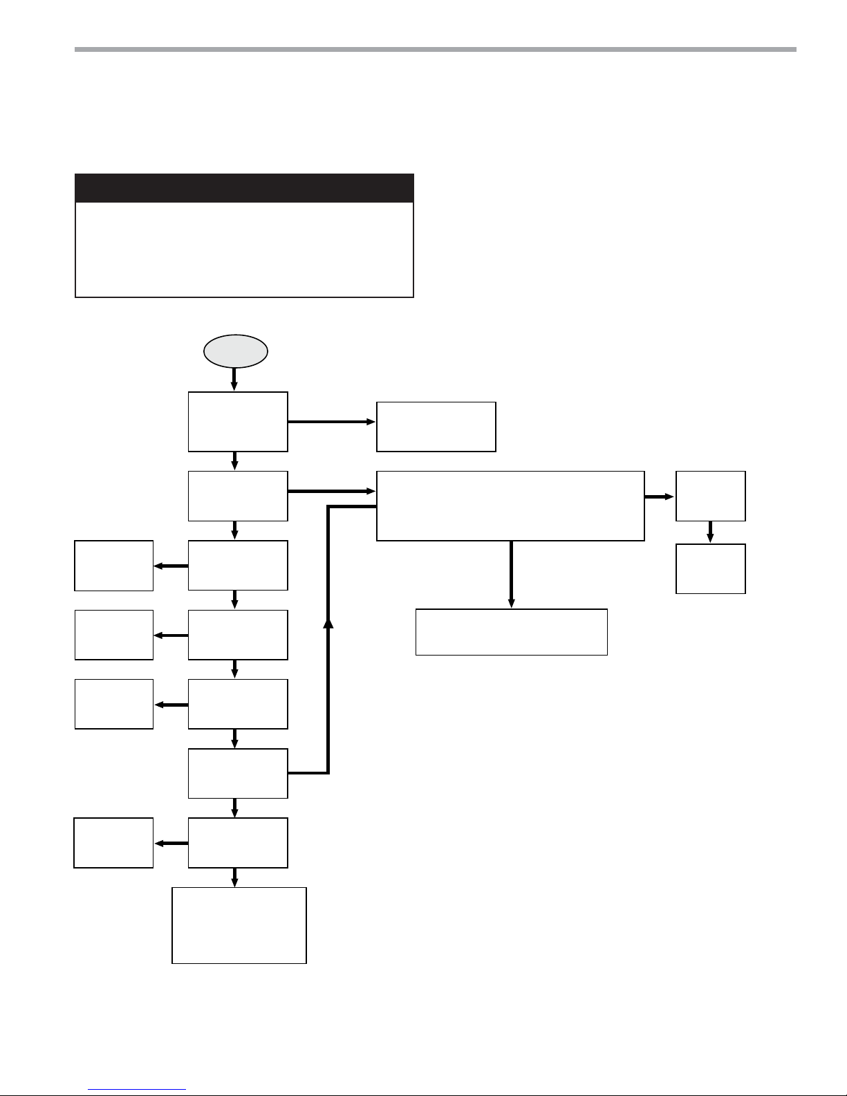
THE SMART SOLUTION FOR ENERGY EFFICIENCY
WARNING!
WARNING! HAZARDOUS VOLTAGE! DISCONNECT
ALL ELECTRIC POWER INCLUDING REMOTE
DISCONNECTS BEFORE SERVICING.
Failure to disconnect power before servicing can cause
severe personal injury or death.
Start
DXM2 Functional
Troubleshooting Flow Chart
See “Unit
short
cycles”
Yes
Did Unit
Attempt to
Start?
Yes
Did Unit
Lockout at
Start-up?
No
Unit Short
Cycles?
No
No
Yes
Tranquility
Check Main
power (see power
problems)
Check fault code on communicating
thermostat (ATC32) or Configuration
and Diagnostics Tool (ACD01)
®
22 (TY) Series
Rev.: 12/17/14
DXM2 Process Flow Chart
No fault
shown
Replace
DXM2
See “Only
Fan Runs”
See “Only
Comp
Runs”
See “Does
not Operate
in Clg”
Yes
Yes
No
Only Fan
Compressor
Runs?
Did unit lockout
after a period of
operation?
Does unit
operate in
cooling?
Unit is OK!
‘See Performance
Troubleshooting’ for
further help
Runs?
No
Only
No
No
Yes
See fault codes in table
on following page
Yes
climatemaster.com
47
Page 48
CLIMATEMASTER WATER-SOURCE HEAT PUMPS
Tranquility
®
22 (TY) Series
Rev.: 12/17/14
Functional Troubleshooting
Fault Htg Clg Possible Cause Solution
Main power problems
HP Fault
Code 2
XXGreen Status LED Off
X Reduced or no water fl ow in cooling
X Water Temperature out of range in cooling Bring water temp within design parameters.
X Reduced or no air fl ow in heating
High Pressure
X Air temperature out of range in heating Bring return air temp within design parameters.
XXOvercharged with refrigerant Check superheat/subcooling vs typical operating condition table.
XXBad HP Switch Check switch continuity and operation. Replace.
LP/LOC Fault
Code 3
Low Pressure / Loss of Charge
LT1 Fault
Code 4
Water coil low
temperature limit
LT2 Fault
Code 5
Air coil low
temperature limit
Condensate Fault
Code 6
Over/Under
Voltage Code 7
(Auto resetting)
Unit Performance Sentinel
Code 8
Swapped Thermistor
Code 9
ECM Fault - Code 10
Low Air Coil Pressure Fault
(ClimaDry) Code 11
Low Air Coil Temperature
Fault - (ClimaDry) Code 12
XXInsuffi cient charge Check for refrigerant leaks
X Compressor pump down at start-up Check charge and start-up water fl ow.
X Reduced or no water fl ow in heating
X Inadequate antifreeze level Check antifreeze density with hydrometer.
Improper temperature limit setting (30°F vs
X
10°F [-1°C vs -2°C])
X Water Temperature out of range Bring water temp within design parameters.
XXBad thermistor Check temp and impedance correlation per chart
X Reduced or no air fl ow in cooling
X Air Temperature out of range Too much cold vent air? Bring entering air temp within design parameters.
Improper temperature limit setting (30°F vs
X
10°F [-1°C vs -12°C])
XXBad thermistor Check temp and impedance correlation per chart.
XXBlocked drain Check for blockage and clean drain.
XXImproper trap Check trap dimensions and location ahead of vent.
X Poor drainage
X Moisture on sensor Check for moisture shorting to air coil.
XXPlugged air fi lter Replace air fi lter.
xXRestricted Return Air Flow Find and eliminate restriction. Increase return duct and/or grille size.
XXUnder Voltage
XXOver Voltage
X Heating mode LT2>125°F [52°C] Check for poor air fl ow or overcharged unit.
Cooling Mode LT1>125°F [52°C] OR LT2<
X
40ºF [4ºC])
XXLT1 and LT2 swapped Reverse position of thermistors
XX
Blower does not operate
Blower operating with incorrect airfl ow
X
Reduced or no air fl ow in cooling or ClimaDry
Air temperature out of range Too much cold vent air - bring entering air temp within design parameters
Bad pressure switch Check switch continuity and operation - replace
X
Reduced airfl ow in cooling, ClimaDry, or
constant fan
Air temperature out of range Too much cold vent air - bring entering air temp within design parameters
Bad thermistor Check temp and impedance correlation per chart
Check line voltage circuit breaker and disconnect.
Check for line voltage between L1 and L2 on the contactor.
Check for 24VAC between R and C on CXM/DXM'
Check primary/secondary voltage on transformer.
Check pump operation or valve operation/setting.
Check water fl ow adjust to proper fl ow rate.
Check for dirty air fi lter and clean or replace.
Check fan motor operation and airfl ow restrictions.
Dirty Air Coil- construction dust etc.
Too high of external static. Check static vs blower table.
Check pump operation or water valve operation/setting.
Plugged strainer or fi lter. Clean or replace..
Check water fl ow adjust to proper fl ow rate.
Clip JW3 jumper for antifreeze (10°F [-12°C]) use.
Check for dirty air fi lter and clean or replace.
Check fan motor operation and airfl ow restrictions.
Too high of external static. Check static vs blower table.
Normal airside applications will require 30°F [-1°C] only.
Check for piping slope away from unit.
Check slope of unit toward outlet.
Poor venting. Check vent location.
Check power supply and 24VAC voltage before and during operation.
Check power supply wire size.
Check compressor starting. Need hard start kit?
Check 24VAC and unit transformer tap for correct power supply voltage.
Check power supply voltage and 24VAC before and during operation.
Check 24VAC and unit transformer tap for correct power supply voltage.
Check for poor water fl ow, or air fl ow.
Check blower line voltage
Check blower low voltage wiring
Wrong unit size selection
Wrong unit family selection
Wrong motor size
Incorrect blower selection
Check for dirty air fi lter and clean or replace
Check fan motor operation and airfl ow restrictions
Too high of external static - check static vs blower table
Check for dirty air fi lter and clean or replace
Check fan motor operation and airfl ow restrictions
Too high of external static - check static vs blower table
Table Continued on Next Page
48
ClimateMaster Water-Source Heat Pumps
Page 49
THE SMART SOLUTION FOR ENERGY EFFICIENCY
Fault Htg Clg Possible Cause Solution
ESD - ERV Fault (DXM Only)
Green Status LED Code 3
No Fault Code Shown
Unit Short Cycles
Only Fan Runs
XXERV unit has fault (Rooftop units only) Troubleshoot ERV unit fault
No compressor operation See ‘Only Fan Operates’
XX
Compressor overload Check and replace if necessary
Control board Reset power and check operation
Dirty air fi lter Check and clean air fi lter
Unit in ‘Test Mode’ Reset power or wait 20 minutes for auto exit
XX
Unit selection Unit may be oversized for space - check sizing for actual load of space
Compressor overload Check and replace if necessary
Thermostat position Ensure thermostat set for heating or cooling operation
Unit locked out Check for lockout codes - reset power
XX
Compressor overload Check compressor overload - replace if necessary
Thermostat wiring
Check thermostat wiring at DXM2 - put in Test Mode and jumper Y1 and R to
give call for compressor
Tranquility
®
22 (TY) Series
Rev.: 12/17/14
Functional Troubleshooting (cont.)
climatemaster.com
49
Page 50
CLIMATEMASTER WATER-SOURCE HEAT PUMPS
Symptom Htg Clg Possible Cause Solution
Insufficient Capacity/
X X Dirty filter Replace or clean
Not Cooling or Heating
Rduced or no air flow
Check for dirty air filter and clean or replace
Properly
in heating
Check fan motor operation and airflow restrictions
Too high of external static - check static vs blower table
Reduced or no air flow
Check for dirty air filter and clean or replace
in cooling
Check fan motor operation and airflow restrictions
Too high of external static - check static vs blower table
X X Leaky duct work
Check supply and return air temperatures at the unit and at
distant duct registers if significantly different, duct leaks
are present
X X Low refrigerant charge Check superheat and subcooling per chart
X X Restricted metering device Check superheat and subcooling per chart - replace
X Defective reversing valve Perform RV touch test
X X Thermostat improperly located Check location and for air drafts behind stat
X X Unit undersized
Recheck loads & sizing check sensible clg load and heat
pump capacity
X X Scaling in water heat exchanger Perform Scaling check and clean if necessary
X X Inlet water too hot or cold Check load, loop sizing, loop backfill, ground moisture
High Head Pressure
X
Reduced or no air flow
Check for dirty air filter and clean or replace
in heating
Check fan motor operation and airflow restrictions
Too high of external static - check static vs blower table
X Reduced or no water flow Check pump operation or valve operation/setting
in cooling
Check water flow adjust to proper flow rate
X Inlet water too hot Check load, loop sizing, loop backfill, ground moisture
X
Air temperature out of range in
heating
Bring return air temp within design parameters
X Scaling in water heat exchanger Perform Scaling check and clean if necessary
X X Unit overcharged Check superheat and subcooling - reweigh in charge
X X Non-condensables insystem Vacuum system and reweigh in charge
X X Restricted metering device Check superheat and subcooling per chart - replace
Low Suction Pressure
X
Reduced water flow
Check pump operation or water valve operation/setting
in heating
Plugged strainer or filter - clean or replace
Check water flow adjust to proper flow rate
X Water temperature out of range Bring water temp within design parameters
X
Reduced air flow
Check for dirty air filter and clean or replace
in cooling
Check fan motor operation and airflow restrictions
Too high of external static - check static vs blower table
X Air temperature out of range
Too much cold vent air - bring entering air temp within
design parameters
X X Insufficient charge Check for refrigerant leaks
Low Dischage Air
Temperature in Heating
X Too high of air flow Check fan motor speed selection and airflow chart
X Poor performance See “Insufficient Capacity”
X
X
S
n
Symptom
g
Clg
e
f
ficient Capacity/
g
operl
y
essur
e
r
essur
e
T
Tranquility
Rev.: 12/17/14
®
22 (TY) Series
Performance Troubleshooting
t
nsu
Not Cooling or Heatin
gh Head Pr
Possible Caus
olutio
Low Suction P
ow Dischage Air
emperature in Heating
50
ClimateMaster Water-Source Heat Pumps
Page 51
THE SMART SOLUTION FOR ENERGY EFFICIENCY
High Humidity
X Too high of air flow Check fan motor speed selection and airflow chart
X Unit oversized
Recheck loads and sizing check sensible clg load and
heat pump capacity
Only Compressor Runs
X X Thermostat wiring
Check G wiring at heat pump. Jumper G and R for fan
operation.
X X Fan motor relay
Jumper G and R for fan operation. Check for Line voltage
across blower relay contacts.
Check fan power enable relay operation (if present)
X X Fan motor Check for line voltage at motor. Check capacitor
X X Thermostat wiring
Check thermostat wiring at or DXM2. Put in Test Mode
and then jumper Y1 and W1 to R to give call for fan,
compressor and electric heat.
Unit Doesn't Operate in
Cooling
X Reversing Valve
Set for cooling demand and check 24VAC on RV coil.
If RV is stuck, run high pressure up by reducing water flow
and while operating engage and disengage RV coil voltage
to push valve.
X Thermostat setup
X Thermostat wiring
Check O wiring at heat pump. DXM2 requires call for
compressor to get RV coil “Click.”
Modulating Valve
Troubleshooting
X
Improper output setting
Verify the AO-2 jumper is in the 0-10V position
No valve operation
Check voltage to the valve
X
No valve output signal
Check DC voltage between AO2 and GND. Should be O
when valve is off and between 3.3v and 10v when valve
is on.
Replace valve if voltage and control signals are present at
the valve and it does not operate
For DXM2 check for “O” RV setup not “B”.
idity
Only Compr
essor Runs
n
C
n
g
T
Symptom Htg Clg Possible Cause Solution
S
n
e
g
Clg
S
m
ympto
Hum
Unit Doesn't Operate i
ooli
Tranquility
®
22 (TY) Series
Rev.: 12/17/14
Performance Troubleshooting (continued)
t
Possible Caus
olutio
Modulating Valve
roubleshooting
climatemaster.com
51
Page 52
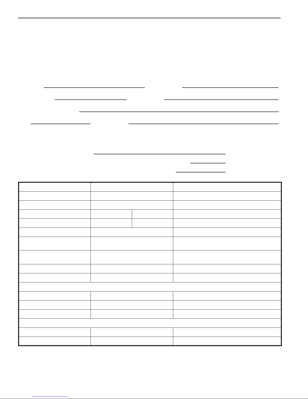
CLIMATEMASTER WATER-SOURCE HEAT PUMPS
Tranquility
Rev.: 12/17/14
®
22 (TY) Series
Start-Up Log Sheet
Installer: Complete unit and system checkout and follow unit start-up procedures in the IOM. Use this form to record
unit information, temperatures and pressures during start-up. Keep this form for future reference.
Job Name: Street Address:
Model Number: Serial Number:
Unit Location in Building:
Date: Sales Order No:
In order to minimize troubleshooting and costly system failures, complete the following checks and data entries before
the system is put into full operation.
Fan Motor: CFM Settings (ECM)
Temperatures: F or C Antifreeze: %
Pressures: PSIG or kPa Type
Cooling Mode Heating Mode
Entering Fluid Temperature
Leaving Fluid Temperature
Temperature Differential
Return-Air Temperature DB WB DB
Supply-Air Temperature DB WB DB
Temperature Differential
Water Coil Heat Exchanger
(Water Pressure IN)
Water Coil Heat Exchanger
(Water Pressure OUT)
Pressure Differential
Water Flow GPM
Compressor
Amps
Volts
Discharge Line Temperature
Motor
Amps
Volts
Allow unit to run 15 minutes in each mode before taking data.
Note: Never connect refrigerant gauges during startup procedures. Conduct water-side analysis using P/T
ports to determine water flow and temperature difference. If water-side analysis shows poor performance,
refrigerant troubleshooting may be required. Connect refrigerant gauges as a last resort.
52
ClimateMaster Water-Source Heat Pumps
Page 53
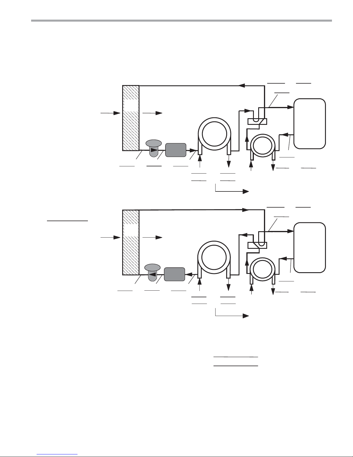
THE SMART SOLUTION FOR ENERGY EFFICIENCY
s
Refrigerant Circuit Diagram
+($7,1*&<&/($1$/ <6,6
&22/,1*&<&/($1$/<6,6
5HIULJHUDQW7\SH
+)&$
$,5
&2,/
$) $)
(;3$16,21
9$/9 (
$)
)3+($7,1*
/,48,'/,1(
)/$6+
*$6/,1(
$,5
&2,/
$) $)
$)
),/7(5
'5,(5
)3
6(1625
Tranquility
&2$;
$)
$) $)
36, 36,
:$7(5,1 :$7(5287
®
22 (TY) Series
Rev.: 12/17/14
Functional Troubleshooting
36,
$)
+:*
$)
36,
Look up pressure drop in
I.O.M. or spec. catalog to
determine flow rate.
36,
$)
6$7
68&7,21
&2035(6625
',6&+$5*(
6$7
6$7
68&7,21
&2035(6625
$)
),/7(5
'5,(5
)3&/*
/,4/,1(
&2$;
$)
$) $)
36, 36,
:$7(5,1 :$7(5287
',6&+$5*(
+:*
$)
36,
6$7
Look up pressure drop in
9ROWDJHBBBBBBBB
&RPS$PSVBBBBBBB
7RWDO$PSVBBBBBBBB
)3)/$6+
*$6/,1(
(;3$16,21
9$/9 (
$)
27+(56,'(
2)),/75'5
I.O.M. or spec. catalog to
determine flow rate.
+HDWRI([WUDFWLRQ$EVRUSWLRQRU+HDWRI5HMHFWLRQ
________ IORZUDWH GLII IDFWRU BBBBBBBBBBBBB
6XSHUKHDW
6XEFRROLQJ
8VHIRUZDWHUIRUDQWLIUHH]H
JSP[BBBBBBBBWHPS GHJ)[BBBBBBBBIOXLG
6XFWLRQWHPSHUDWXUH VXFWLRQVDWXUDWLRQWHPS
'LVFKDUJHVDWXUDWLRQWHPS OLTXLGOLQHWHPS
Note: Never connect refrigerant gauges during startup procedures. Conduct water-side analysis using P/T
ports to determine water flow and temperature difference. If water-side analysis shows poor performance,
refrigerant troubleshooting may be required. Connect refrigerant gauges as a last resort.
%WXKU
GHJ)
GHJ)
5HY
climatemaster.com
53
Page 54
CLIMATEMASTER WATER-SOURCE HEAT PUMPS
CLIMATE MASTER, INC.
LIMITED EXPRESS WARRANTY/ LIMITATION OF REMEDIES AND LIABILITY
It is expressly understood that unless a statement is speciÀ cally identiÀ ed as a warranty, statements made by Climate Master, Inc., a Delaware corporation, (“CM”) or its representatives, relating to CM’s products, whether oral,
written or contained in any sales literature, catalog or any other agreement, are not express warranties and do not form a part of the basis of the bargain, but are merely CM’s opinion or commendation of CM’s products.
EXCEPT AS SPECIFICALLY SET FORTH HEREIN, THERE IS NO EXPRESS WARRANTY AS TO ANY OF CM’S PRODUCTS. CM MAKES NO WARRANTY AGAINST LATENT DEFECTS. CM MAKES
NO WARRANTY OF MERCHANTABILITY OF THE GOODS OR OF THE FITNESS OF THE GOODS FOR ANY PARTICULAR PURPOSE.
GRANT OF LIMITED EXPRESS WARRANTY
CM warrants CM products purchased and retained in the United States of America and Canada to be free from defects in material and workmanship under normal use and maintenance as follows: (1) All complete air condition-
ing, heating and/or heat pump units built or sold by CM for twelve (12) months from date of unit start up or eighteen (18) months from date of shipment (from factory), whichever comes À rst; (2) Repair and replacement parts,
which are not supplied under warranty, for nintey (90) days from date of shipment (from factory). All parts must be returned to CM’s factory in Oklahoma City, Oklahoma, freight prepaid, no later than sixty (60) days after
the date of the failure of the part; if CM determines the part to be defective and within CM’s Limited Express Warranty, CM shall, when such part has been either replaced or repaired, return such to a factory recognized dealer,
contractor or service organization, F.O.B. CM’s factory, Oklahoma City, Oklahoma, freight prepaid. The warranty on any parts repaired or replaced under warranty expires at the end of the original warranty period.
This warranty does not cover and does not apply to: (1) Air À lters, fuses, refrigerant, Á uids, oil; (2) Products relocated after initial installation; (3) Any portion or component of any system that is not supplied by CM, regardless
of the cause of the failure of such portion or component; (4) Products on which the unit identiÀ cation tags or labels have been removed or defaced; (5) Products on which payment to CM is or has been in default; (6) Products
which have defects or damage which result from improper installation, wiring, electrical imbalance characteristics or maintenance; or are caused by accident, misuse or abuse, À re, Á ood, alteration or misapplication of the prod-
uct; (7) Products which have defects or damage which result from a contaminated or corrosive air or liquid supply, operation at abnormal temperatures, or unauthorized opening of refrigerant circuit; (8) Mold, fungus or bacteria
damages; (9) Products subjected to corrosion or abrasion; (10) Products manufactured or supplied by others; (11) Products which have been subjected to misuse, negligence or accidents; (12) Products which have been operated
in a manner contrary to CM’s printed instructions; or (13) Products which have defects, damage or insufÀ cient performance as a result of insufÀ cient or incorrect system design or the improper application of CM’s products.
CM is not responsible for: (1) The costs of any Á uids, refrigerant or other system components, or associated labor to repair or replace the same, which is incurred as a result of a defective part covered by CM’s Limited Express
Warranty; (2) The costs of labor, refrigerant, materials or service incurred in removal of the defective part, or in obtaining and replacing the new or repaired part; or, (3) Transportation costs of the defective part from the installa-
tion site to CM or of the return of any part not covered by CM’s Limited Express Warranty.
Limitation: This Limited Express Warranty is given in lieu of all other warranties. If, notwithstanding the disclaimers contained herein, it is determined that other warranties exist, any such warranties, including without limita-
tion any express warranties or any implied warranties of À tness for particular purpose and merchantability, shall be limited to the duration of the Limited Express Warranty.
LIMITATION OF REMEDIES
In the event of a breach of the Limited Express Warranty, CM will only be obligated at CM’s option to repair the failed part or unit or to furnish a new or rebuilt part or unit in exchange for the part or unit which has failed. If
after written notice to CM’s factory in Oklahoma City, Oklahoma of each defect, malfunction or other failure and a reasonable number of attempts by CM to correct the defect, malfunction or other failure and the remedy fails
of its essential purpose, CM shall refund the purchase price paid to CM in exchange for the return of the sold good(s). Said refund shall be the maximum liability of CM. THIS REMEDY IS THE SOLE AND EXCLUSIVE
REMEDY OF THE BUYER OR THEIR PURCHASER AGAINST CM FOR BREACH OF CONTRACT, FOR THE BREACH OF ANY WARRANTY OR FOR CM’S NEGLIGENCE OR IN STRICT LIABILITY.
LIMITATION OF LIABILITY
CM shall have no liability for any damages if CM’s performance is delayed for any reason or is prevented to any extent by any event such as, but not limited to: any war, civil unrest, government restrictions or restraints, strikes
or work stoppages, À re, Á ood, accident, shortages of transportation, fuel, material, or labor, acts of God or any other reason beyond the sole control of CM. CM EXPRESSLY DISCLAIMS AND EXCLUDES ANY LIABIL-
ITY FOR CONSEQUENTIAL OR INCIDENTAL DAMAGE IN CONTRACT, FOR BREACH OF ANY EXPRESS OR IMPLIED WARRANTY, OR IN TORT, WHETHER FOR CM’s NEGLIGENCE OR AS
STRICT LIABILITY.
OBTAINING WARRANTY PERFORMANCE
Normally, the contractor or service organization who installed the products will provide warranty performance for the owner. Should the installer be unavailable, contact any CM recognized dealer, contractor or service organiza-
tion. If assistance is required in obtaining warranty performance, write or call:
Climate Master, Inc. • Customer Service • 7300 S.W. 44th Street • Oklahoma City, Oklahoma 73179 (405) 745-6000
NOTE: Some states or Canadian provinces do not allow limitations on how long an implied warranty lasts, or the limitation or exclusions of consequential or incidental damages, so the foregoing exclusions and limitations may
not apply to you. This warranty gives you speciÀ c legal rights, and you may also have other rights which vary from state to state and from Canadian province to Canadian province.
Please refer to the CM Installation, Operation and Maintenance Manual for operating and maintenance instructions.
*LC083*
Rev.: 11/09 LC083
Tranquility
®
22 (TY) Series
Rev.: 12/17/14
Warranty (U.S. & Canada)
ClimateMaster Water-Source Heat Pumps
54
Page 55
THE SMART SOLUTION FOR ENERGY EFFICIENCY
Rev.: 10/09
Tranquility
APPLICABLE LAW, THIS REMEDY IS THE SOLE AND EXCLUSIVE REMEDY OF THE CUSTOMER AGAINST CM FOR BREACH OF CONTRACT, FOR THE BREACH OF ANY WARRANTY OR FOR CM’S NEGLIGENCE
OR IN STRICT LIABILITY.
LIMITATION OF LIABILITY
CM shall have no liability for any damages if CM’s performance is delayed for any reason or is prevented to any extent by any event such as, but not limited to: any war, civil unrest, government restrictions or restraints, strikes, or work stoppages,
À re, Á ood, accident, allocation, shortages of transportation, fuel, materials, or labor, acts of God or any other reason beyond the sole control of CM. TO THE FULLEST EXTENT PERMITTED BY APPLICABLE LAW AND SUBJECT TO
THE NEXT SENTENCE, CM EXPRESSLY DISCLAIMS AND EXCLUDES ANY LIABILITY FOR LOSS OF PROFITS, LOSS OF BUSINESS OR GOODWILL, CONSEQUENTIAL, INCIDENTAL, SPECIAL, LIQUIDATED, OR
PUNITIVE DAMAGE IN CONTRACT, FOR BREACH OF ANY EXPRESS OR IMPLIED WARRANTY, OR IN TORT, WHETHER FOR CM’s NEGLIGENCE OR AS STRIC
exclude CM’s liability for death, personal injury or fraud.
OBTAINING WARRANTY PERFORMANCE
Normally, the contractor or service organization who installed the products will provide warranty performance for the owner. Should the installer be unavailable, contact any CM recognized Representative. If assistance is required in obtaining warranty
performance, write or call:
Climate Master, Inc. • Customer Service • 7300 S.W. 44th Street • Oklahoma City, Oklahoma, U.S.A. 73179 • (405) 745-6000 • FAX (405) 745-6068
NOTE: Some countries do not allow limitations on how long an implied warranty lasts, or the limitation or exclusions of consequential or incidental damages, so the foregoing exclusions and limitations may not apply to you. This warranty gives you
speciÀ c legal rights, and you may also have other rights which vary from state to state and country to country.
Please refer to the CM Installation, Operation and Maintenance Manual for operating and maintenance instructions.
change for the part or unit which has failed. If after written notice to CM’s factory in Oklahoma City, Oklahoma, U.S.A. of each defect, malfunction or other failure and a reasonable number of attempts by CM to correct the defect, malfunction or other
failure and the remedy fails of its essential purpose, CM shall refund the purchase price paid to CM in exchange for the return of the sold good(s). Said refund shall be the maximum liability of CM. TO THE FULLEST EXTENT PERMITTED BY
part not covered by CM’s Limited Express Warranty; or (4) The costs of normal maintenance.
Limitation: This Limited Express Warranty is given in lieu of all other warranties. If, notwithstanding the disclaimers contained herein, it is determined by a court or other qualiÀ ed judicial body that other warranties exist, any such warranty, including
without limitation any express warranty or any implied warranty of À tness for particular purpose and merchantability, shall be limited to the duration of the Limited Express Warranty. This Limited Express Warranty does not exclude any warranty that is
mandatory and that may not be excluded under applicable imperative law.
LIMITATION OF REMEDIES
In the event of a breach of this Limited Express Warranty or any warranty that is mandatory under applicable imperative law, CM will only be obligated at CM’s option to either repair the failed part or unit or to furnish a new or rebuilt part or unit in ex-
of the refrigerant circuit; (8) Mold, fungus or bacteria damages; (9) Products subjected to corrosion or abrasion; (10) Products, parts or components manufactured or supplied by others; (11) Products which have been subjected to misuse, negligence
or accidents; (12) Products which have been operated in a manner contrary to CM’s printed instructions; (13) Products which have defects, damage or insufÀ cient performance as a result of insufÀ cient or incorrect system design or the improper
application, installation, or use of CM’s products; or (14) Electricity or fuel costs, or any increases or unrealized savings in same, for any reason.
CM is not responsible for: (1) The cost of any Á uids, refrigerant or other system components, or the associated labor to repair or replace the same, which is incurred as a result of a defective part covered by CM’s Limited Express Warranty; (2) The cost
of labor, refrigerant, materials or service incurred in diagnosis and removal of the defective part, or in obtaining and replacing the new or repaired part; (3) Transportation costs of the defective part from the installation site to CM or of the return of any
expires at the end of the original warranty period.
This warranty does not cover and does not apply to: (1) Air À lters, fuses, refrigerant, Á uids, oil; (2) Products relocated after initial installation; (3) Any portion or component of any system that is not supplied by CM, regardless of the cause of the failure
of such portion or component; (4) Products on which the unit identiÀ cation tags or labels have been removed or defaced; (5) Products on which payment by Customer to CM or its distributors or Representatives, or the Customer’s seller is in default;
(6) Products which have defects or damage which result from improper installation, wiring, electrical imbalance characteristics or maintenance; or from parts or components manufactured by others; or are caused by accident, misuse, negligence, abuse,
À re, Á ood, lightning, alteration or misapplication of the product; (7) Products which have defects or damage which result from a contaminated or corrosive air or liquid supply, operation at abnormal temperatures or Á ow rates, or unauthorized opening
®
22 (TY) Series
Rev.: 12/17/14
Warranty (International)
Disclaimer: It is expressly understood that unless a statement is speciÀ cally identiÀ ed as a warranty, statements made by Climate Master, Inc., a Delaware corporation, U. S. A. (“CM”) or its representatives, relating to CM’s products, whether oral, writ-
ten or contained in any sales literature, catalog, this or any other agreement or other materials, are not express warranties and do not form a part of the basis of the bargain, but are merely CM’s opinion or commendation of CM’s products. EXCEPT AS
SPECIFICALLY SET FORTH HEREIN AND TO THE FULLEST EXTENT PERMITTED BY APPLICABLE LAW, CM MAKES NO WARRANTY AS TO ANY OF CM’S PRODUCTS, AND CM MAKES NO WARRANTY AGAINST
LATENT DEFECTS OR ANY WARRANTY OF MERCHANTABILITY OF THE GOODS OR OF THE FITNESS OF THE GOODS FOR ANY PARTICULAR PURPOSE.
GRANT OF LIMITED EXPRESS WARRANTY
CM warrants CM products purchased and installed outside the United States of America (“U.S.A.”) and Canada to be free from material defects in materials and workmanship under normal use and maintenance as follows: (1) All complete air
conditioning, heating or heat pump units built or sold by CM for twelve (12) months from date of unit start-up or eighteen (18) months from date of shipment (from CM’s factory), whichever comes À rst; and, (2) Repair and replacement parts, which are
not supplied under warranty, for ninety (90) days from date of shipment (from factory).
Warranty parts shall be furnished by CM if ordered through an authorized sales representative of CM (“Representative”) within sixty (60) days after the failure of the part. If CM determines that a parts order qualiÀ es for replacement under CM’s
warranty, such parts shall be shipped freight prepaid to the Representative or the ultimate user, as requested by Representative. All duties, taxes and other fees shall be paid by the ultimate user through the Representative.
If requested by CM, all defective parts shall be returned to CM’s factory in Oklahoma City, Oklahoma, U.S.A, freight and duty prepaid, not later than sixty (60) days after the date of the request. If the defective part is not timely returned or if CM
determines the part to not be defective or otherwise not to qualify under CM’s Limited Express Warranty, CM shall invoice Customer the costs for the parts furnished, including freight. The warranty on any part repaired or replaced under warranty
CLIMATE MASTER, INC.
LIMITED EXPRESS WARRANTY /LIMITATION OF REMEDIES AND LIABILITY
(FOR INTERNATIONAL CLASS PRODUCTS)
*LC079*
LC079
T LIABILITY. Nothing in this Agreement is intended to
climatemaster.com
55
Page 56
CLIMATEMASTER WATER-SOURCE HEAT PUMPS
Tranquility
®
22 (TY) Series
Rev.: 12/17/14
Revision History
Date: Item: Action:
12/17/14
07/25/14
06/13/14
03/24/14
10/08/13
10/07/13
03/07/13
11/09/12
06/20/12 First Published
Table - Page 6
Page 17, 20, 23, 37
Page 8, 11 & 19
Table 10
Table 7b
Figure 10a: Vertical Condensate Drain
POE Oil Warning
Wiring Diagrams
Nominal Resistance Table
Condensate Drain Connection
Water Quality Table
Updated
Misc. Edits
Change Text - Filter “rack” to “frame”
Updated Water Quality Table
Updated PD for 024, 036, 060
Updated
Updated
Added
Updated
ISO 9001:2008
Certified
Quality: First & Always
T
O
D
E
A
I
R
F
I
I
T
A
R
S
E
C
C
O
R
E
R
U
T
C
A
F
U
N
A
M
I
S
O
M
B
P
R
R
I
L
A
I
N
Y
E
O
I
T
N
T
O
R
E
T
A
W
S
G
A
W
I
R
I
T
H
R
H
S
E
P
A
M
T
U
P
1
-
6
5
2
T
3
A
1
N
D
D
A
R
*97B0075N15*
97B0075N15
ClimateMaster works continually to improve its products. As a result, the design and specifi cations of each product at the time for order may be changed
without notice and may not be as described herein. Please contact ClimateMaster’s Customer Service Department at 1-405-745-6000 for specifi c
information on the current design and specifi cations. Statements and other information contained herein are not express warranties and do not form
the basis of any bargain between the parties, but are merely ClimateMaster’s opinion or commendation of its products.
The management system governing the manufacture of ClimateMaster’s products is ISO 9001:2008 certifi ed.
ClimateMaster is a proud supporter of the Geothermal Exchange Organization - GEO. For more information visit geoexchange.org.
© ClimateMaster, Inc. 2009
56
ClimateMaster Water-Source Heat Pumps
7300 S.W. 44th Street
Oklahoma City, OK 73179
Phone: 405-745-6000
Fax: 405-745-6058
climatemaster.com
 Loading...