

ClimateMaster Tranquility 16 Series, Tranquility 16 TC Series Installation Operation & Maintenance
Tranquility® 16
(TC) Series
Commercial Horizontal
& Vertical Packaged
Water-Source Heat Pumps
50HZ-HFC-410A
INSTALLATION, OPERATION
&
MAINTENANCE
97B0075N02
Revised: 25 July, 2017
Table of Contents
Model Nomenclature 3
General Information 4
Unit Physical Data 6
Horizontal Installation 7
Field Conversion of Air Discharge 10
Horizontal Installation 11
Duct System Installation 12
Vertical Installation 13
Piping Installation 16
Water-Loop Heat Pump Applications 17
Ground-Loop Heat Pump Applications 18
Ground-Water Heat Pump Applications 20
Water Quality Standards 22
Electrical - Line Voltage 23
Electrical - Power Wiring 24
Electrical - Power & Low Voltage Wiring 25
Electrical - Low Voltage Wiring 26
Electrical - Thermostat Wiring 27
Typical Wiring Diagrams 28
CXM Controls 34
DXM Controls 35
CXM and DXM Controls 37
Operating Limits 39
Piping System Cleaning and Flushing 40
Unit Starting and Operating Conditions 41
Unit Start-Up Procedure 42
Preventive Maintenance 44
Functional Troubleshooting 45
Performance Troubleshooting 46
Functional Troubleshooting - S-I Units 47
Warranty 48
Revision History 52

CLIMATEMASTER WATER-SOURCE HEAT PUMPS
2
ClimateMaster Water-Source Heat Pumps
Tranquility 16 (TC) Series
Rev.: 25 July, 2017
This Page Intentionally Left Blank
THE SMART SOLUTION FOR ENERGY EFFICIENCY
3
climatemaster.com
Tranquility 16 (TC) Series
Rev.: 25 July, 2017
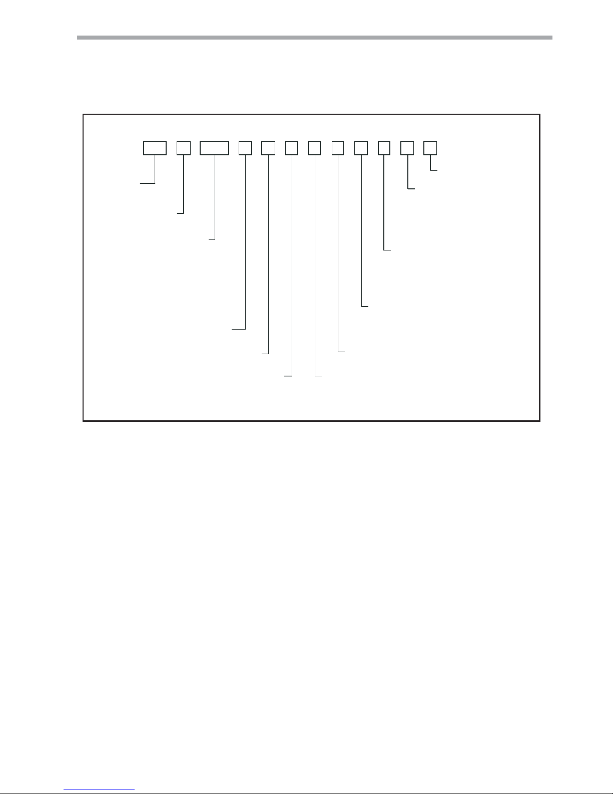
Model Nomenclature
General Overview
T C H A0 3 6 FU 3 0 A L B S
1 2 3 4 5 6 7
8
9101112131415
TC= TRANQUILITY® COMPACT (HFC-410A)
MODEL TYPE
H = HORIZONTAL
CONFIGURATION
V = VERTICAL
UNIT SIZE
006 - V
009 - V
012 -V
015 - V
018 - V
024 - V
REVISION LEVEL
A = CURRENT REVISION FOR ALL SIZES
VOLTAGE
F = CXM
CONTROLS
G = DXM
H = CXM w/LON
J = DXM w/LON
T = CXM w/MPC
U = DXM w/MPC
1 = EXTENDED RANGE
CABINET INSULATION
2 = EXTENDED RANGE w/ULTRA QUIET
0 = NONE
FUTURE USE
A = Copper Water Coil w/Coated Air Coil
HEAT EXCHANGER OPTIONS
C = Copper Water Coil w/Non-Coated Air Coil
L = LEFT RETURN
RETURN AIR OPTIONS
R = RIGHT RETURN
F = FRONT RETURN, VERTICAL 009 - 030
B = BACK DISCHARGE, HORIZONTAL ONL Y
SUPPLY AIR OPTIONS
Y = BACK DISCHARGE, HIGH STA TIC
HORIZONTAL 015 - 060
T = TOP DISCHARGE, VERTICAL ONL Y
V = TOP DISCHARGE, HIGH STA TIC
VERTICAL 015 - 060
S = STRAIGHT DISCHARGE, HORIZONTAL ONL Y
Z = STRAIGHT DISCHARGE, HIGH STA TIC
HORIZONTAL 015 - 060
S = STANDARD
J = Cupro-nickel Water Coil w/Coated Air Coil
N = Cupro-nickel Water Coil w/Non-Coated Air Coil
3 = STANDARD RANGE
4 = STANDARD RANGE w/ULTRA QUIET
V = LEFT RETURN S.S. DRAIN PAN
W = RIGHT RETURN S.S. DRAIN PAN
Z = FRONT RETURN S.S. DRAIN PAN,
VERTICAL 009-030
{
CE
APPROVED
030 - V, U
036 - V, U
042 - U
048 - U
060 - U
V = 220/240/50/1
U = 380/420/50/3
CLIMATEMASTER WATER-SOURCE HEAT PUMPS
4
ClimateMaster Water-Source Heat Pumps
Tranquility 16 (TC) Series
Rev.: 25 July, 2017
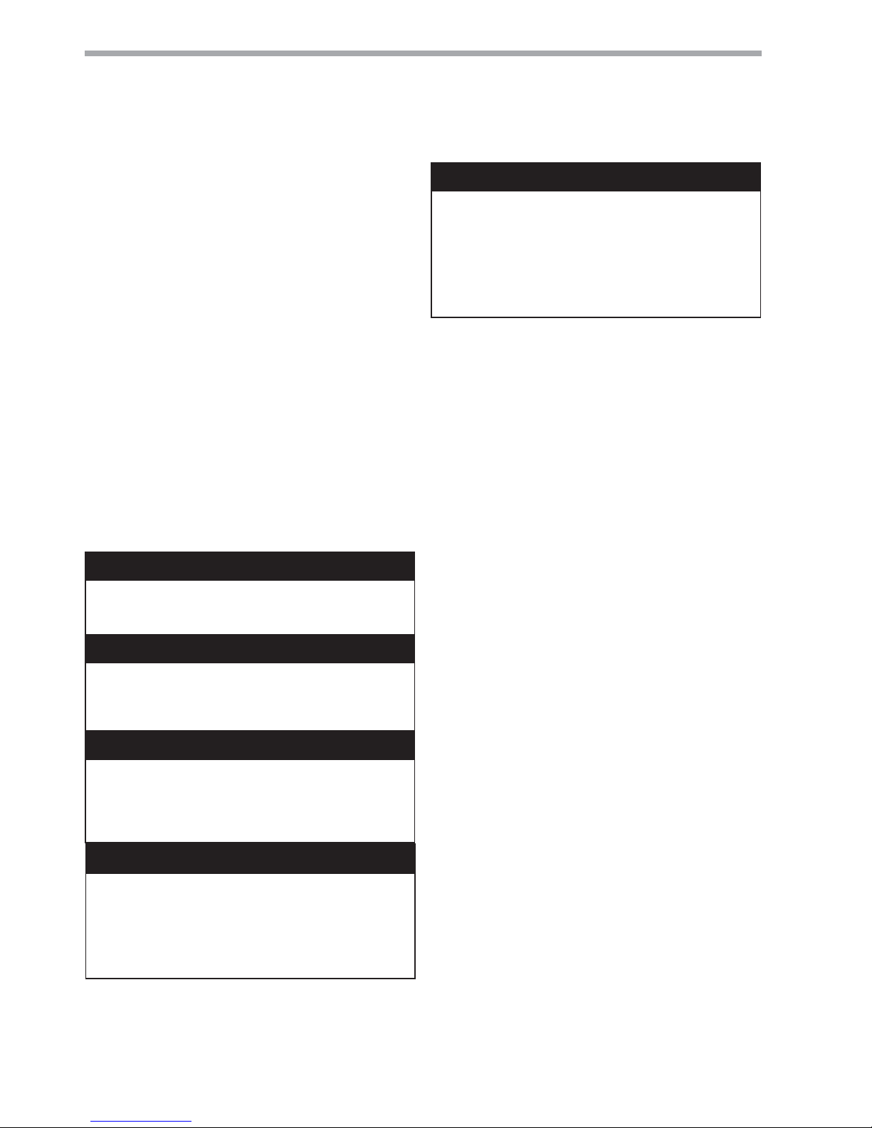
General Information
WARNING! All refrigerant discharged from this unit must
be recovered WITHOUT EXCEPTION. Technicians must
follow industry accepted guidelines and all local, state,
and federal statutes for the recovery and disposal of
refrigerants. If a compressor is removed from this unit,
refrigerant circuit oil will remain in the compressor. To
avoid leakage of compressor oil, refrigerant lines of the
compressor must be sealed after it is removed.
WARNING!
Inspection
Upon receipt of the equipment, carefully check the
shipment against the bill of lading. Make sure all units
have been received. Inspect the packaging of each
unit, and inspect each unit for damage. Ensure that
the carrier makes proper notation of any shortages or
damage on all copies of the freight bill and completes
a common carrier inspection report. Concealed
damage not discovered during unloading must
be reported to the carrier within 15 days of receipt
of shipment. If not fi led within 15 days, the freight
company can deny the claim without recourse. Note: It
is the responsibility of the purchaser to fi le all necessary
claims with the carrier. Notify your equipment supplier
of all damage within fi fteen (15) days of shipment.
Storage
Equipment should be stored in its original packaging in
a clean, dry area. Store units in an upright position at all
times. Stack units a maximum of 3 units high.
Unit Protection
Cover units on the job site with either the original
packaging or an equivalent protective covering.
Cap the open ends of pipes stored on the job site.
In areas where painting, plastering, and/or spraying
has not been completed, all due precautions must
be taken to avoid physical damage to the units and
contamination by foreign material. Physical damage
and contamination may prevent proper start-up and
may result in costly equipment clean-up.
Examine all pipes, fi ttings, and valves before installing
any of the system components. Remove any dirt or
debris found in or on these components.
WARNING! To avoid the release of refrigerant into the
atmosphere, the refrigerant circuit of this unit must be
serviced only by technicians who meet local, state, and
federal profi ciency requirements.
CAUTION! To avoid equipment damage, DO NOT use
these units as a source of heating or cooling during the
construction process. The mechanical components and
fi lters will quickly become clogged with construction dirt
and debris, which may cause system damage.
WARNING!
WARNING!
WARNING!
CAUTION!
WARNING! The EarthPure® Application and Service
Manual should be read and understood before attempting
to service refrigerant circuits with HFC-410A.
WARNING! This appliance is not intended for use by
persons (including children) with reduced physical,
sensory, or mental capabilities, or lack of experience and
knowledge, unless they have been given supervision or
instruction concerning use of the appliance by a person
responsible for their safety.
Saftey
Warnings, cautions, and notices appear throught this
manual. Read these items carefully before attempting
any installation, service, or troubeshooting of the
equipment.
DANGER: Indicates an immediate hazardous situation,
which if not avoided will result in death or serious injury.
DANGER labels on unit access panels must be observed.
WARNING: Indicates an immediate hazardous situation,
which if not avoided will result in death or serious injury.
CAUTION: Indicates a potentially hazardous situation
or an unsafe practice, which if not avoided could result
in minor or moderate injury with product or property
damage.
NOTICE: Notifi cation of installation, operation, or main-
tenance information, which is important, but which is not
hazard-related.
THE SMART SOLUTION FOR ENERGY EFFICIENCY
5
climatemaster.com
Tranquility 16 (TC) Series
Rev.: 25 July, 2017
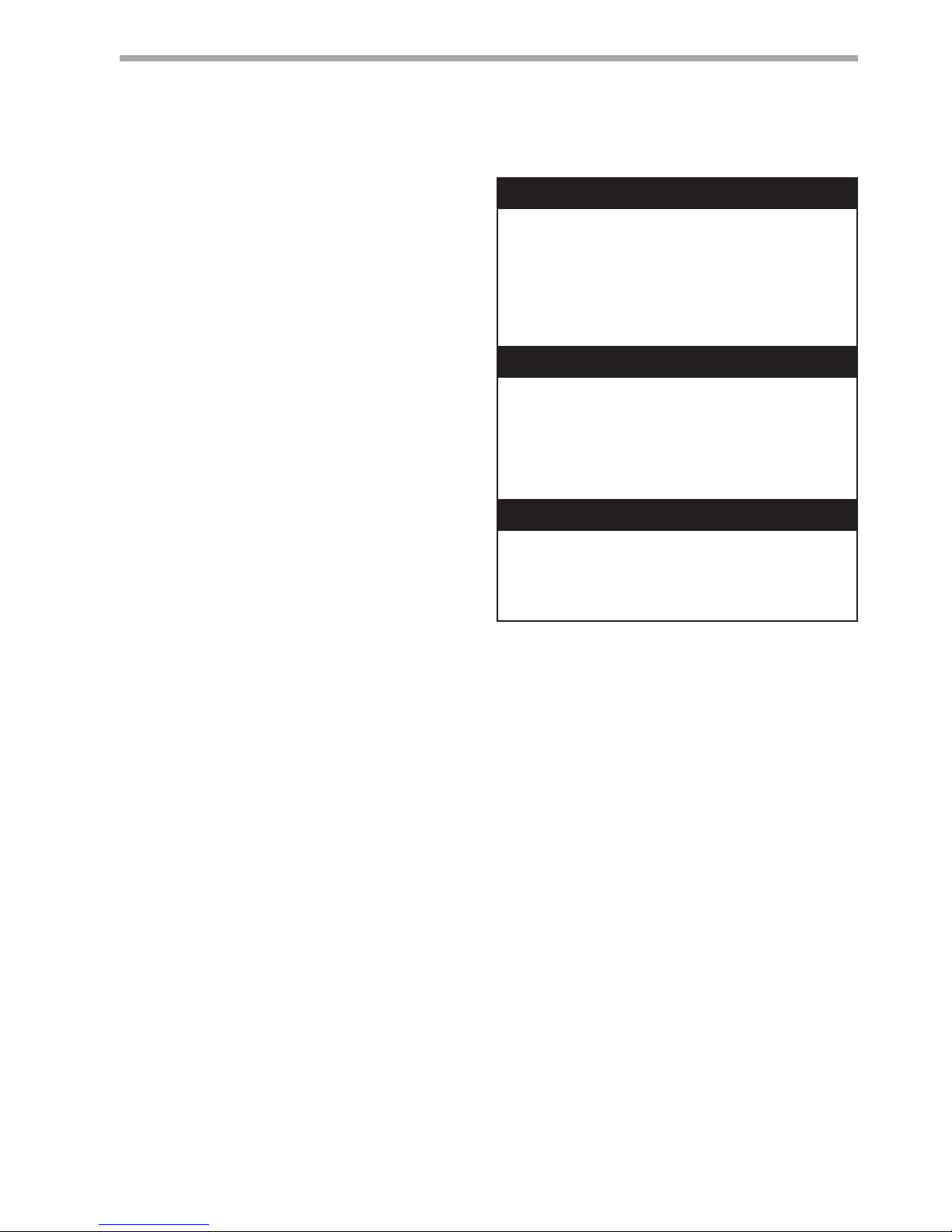
NOTICE! Failure to remove shipping brackets from
spring-mounted compressors will cause excessive
noise, and could cause component failure due to
added vibration.
CAUTION! All three phase scroll compressors must have
direction of rotation verifi ed at start-up. Verifi cation is
achieved by checking compressor Amp draw. Amp draw
will be substantially lower compared to nameplate values.
Additionally, reverse rotation results in an elevated sound
level compared to correct rotation. Reverse rotation will
result in compressor internal overload trip within several
minutes. Verify compressor type before proceeding.
CAUTION! DO NOT store or install units in corrosive
environments or in locations subject to temperature or
humidity extremes (e.g., attics, garages, rooftops, etc.).
Corrosive conditions and high temperature or humidity can
signifi cantly reduce performance, reliability, and service
life. Always move and store units in an upright position.
Tilting units on their sides may cause equipment damage.
CAUTION!
CAUTION!
CAUTION!
CAUTION! CUT HAZARD - Failure to follow this caution
may result in personal injury. Sheet metal parts may have
sharp edges or burrs. Use care and wear appropriate
protective clothing, safety glasses and gloves when
handling parts and servicing heat pumps.
Pre-Installation
Installation, Operation, and Maintenance instructions
are provided with each unit. Horizontal equipment
is designed for installation above false ceiling or in a
ceiling plenum. Other unit confi gurations are typically
installed in a mechanical room. The installation site
chosen should include adequate service clearance
around the unit. Before unit start-up, read all manuals
and become familiar with the unit and its operation.
Thoroughly check the system before operation.
Prepare units for installation as follows:
1. Compare the electrical data on the unit
nameplate with ordering and shipping
information to verify that the correct unit has been
shipped.
2. Keep the cabinet covered with the original
packaging until installation is complete and all
plastering, painting, etc. is fi nished.
3. Verify refrigerant tubing is free of kinks or dents
and that it does not touch other unit components.
4. Inspect all electrical connections. Connections
must be clean and tight at the terminals.
5. Remove any blower support packaging (water-toair units only).
6. Loosen compressor bolts on units equipped with
compressor spring vibration isolation until the
compressor rides freely on the springs. Remove
shipping restraints.
7. Some airfl ow patterns are fi eld convertible
(horizontal units only). Locate the airfl ow
conversion section of this IOM.
8. Locate and verify any hot water generator (HWG),
hanger, or other accessory kit located in the
compressor section or blower section.
CLIMATEMASTER WATER-SOURCE HEAT PUMPS
6
ClimateMaster Water-Source Heat Pumps
Tranquility 16 (TC) Series
Rev.: 25 July, 2017
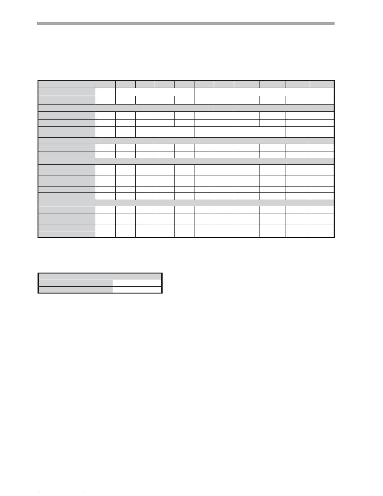
TC Series 006 009 012 015 018 024 030 036 042 048 060
Compressor (1 Each)
Rotary Scroll
Factory Charge HFC-410A - kg
0.48 0.52 .65 0.91 1.22 1.22 1.36 1.42 1.98 2.10 2.32
PSC Fan Motor & Blower
Fan Motor Type/Speeds
PSC/3 PSC/3 PSC/3 PSC/3 PSC/3 PSC/3 PSC/3 PSC/3 PSC/3 PSC/3 PSC/3
Fan Motor (Watts)
30 75 75 124 124 187 560 373 560 560 746
Blower Wheel Size (Dia x w) mm
127 x 127 127 x 127 152 x 127 203 x 178 229 x 178 229 x 203 254 x 254 279 x 254
Water Connection Size
FPT
1/2” 1/2" 1/2” 1/2" 1/2" 3/4" 3/4" 3/4" 3/4" 1" 1"
Coax Volume (liters)
.47 .54 .63 1.08 1.70 1.08 1.22 1.22 3.37 2.79 3.55
Vertical
Air Coil Dimensions (H x W) mm
254 x 381 254x381 254 x 381 508 x 438 508 x 438 508 x 438 508 x 438 610 x 552 610 x 552 610 x 718 610 x 718
Filter Standard - 25.4mm
Throwaway mm
254 x 457 254x457 254 x 457 508 x 508 508 x 508 508 x 508 508 x 508 610 x 610 610 x 610
1-356 x 610,
1- 457 x 610
1-356 x 610,
1- 457 x 610
Weight - Operating kg
47 48 52 69 72 86 89 92 99 119 126
Weight - Packaged kg
51 52 56 72 74 88 92 95 102 123 129
Horizontal
Air Coil Dimensions (H x W) mm
254 x 381 254 x 381 254 x 381 406 x 559 406 x 559 406 x 559 406 x 559 508 x 635 508 x 635 508 x 889 508 x 889
Filter Standard - 25.4mm
Throwaway mm
254 x 457 254 x 457 254 x 457 406 x 635 406 x 635 457 x 635 457 x 635
508 x 711 or
(2) 508 x 356
508 x 711 or
(2) 508 x 356
1-508 x 610,
1-508 x 356
1-508 x 610,
1-508 x 356
Weight - Operating kg
47 47 52 69 72 86 89 92 99 119 138
Weight - Packaged kg
51 52 56 72 74 88 92 95 102 123 141
Notes:
All units have dual isolation compressor mounts for quiet operation, thermal expansion valves for refrigerant metering, and 22.2mm & 28.6mm electrical
knockouts to accommodate fi eld wiring.
FPT - Female Pipe Thread
Condensate Drain Connection is 3/4” FPT
Unit Maximum Water Working Pressure
Options Max Pressure kPa
Base Unit 3447
Tranquility® 16 (TC) Series (50 Hz)
THE SMART SOLUTION FOR ENERGY EFFICIENCY
7
climatemaster.com
Tranquility 16 (TC) Series
Rev.: 25 July, 2017
Horizontal Installation
Horizontal Unit Location
Units are not designed for outdoor installation. Locate
the unit in an INDOOR area that allows enough space
for service personnel to perform typical maintenance
or repairs without removing unit from the ceiling.
Horizontal units are typically installed above a false
ceiling or in a ceiling plenum. Never install units in
areas subject to freezing or where humidity levels could
cause cabinet condensation (such as unconditioned
spaces subject to 100% outside air). Consideration
should be given to access for easy removal of the fi lter
and access panels. Provide suffi cient room to make
water, electrical, and duct connection(s).
If the unit is located in a confi ned space, such as a
closet, provisions must be made for return air to freely
enter the space by means of a louvered door, etc. Any
access panel screws that would be diffi cult to remove
after the unit is installed should be removed prior to
setting the unit. Refer to Figure 3 for an illustration of
a typical installation. Refer to unit submittal data or
engineering design guide for dimensional data.
In limited side access installations, pre-removal of the
control box side mounting screws will allow control box
removal for future servicing.
Conform to the following guidelines when selecting
unit location:
1. Provide a hinged access door in concealed-spline
or plaster ceilings. Provide removable ceiling
tiles in T-bar or lay-in ceilings. Refer to horizontal
unit dimensions for specifi c series and model
in unit submittal data. Size the access opening
to accommodate the service technician during
the removal or replacement of the compressor,
control, or blower assembly. Provide access to
hanger brackets, water valves and fi ttings. Provide
screwdriver clearance to access panels, discharge
collars and all electrical connections.
2. DO NOT obstruct the space beneath the unit
with piping, electrical cables and other items that
prohibit future removal of components or the unit
itself.
3. Use a manual portable jack/lift to lift and support
the weight of the unit during installation and
servicing.
The installation of water source heat pump units and all
associated components, parts and accessories which
make up the installation shall be in accordance with
the regulations of ALL authorities having jurisdiction
and MUST conform to all applicable codes. It is the
responsibility of the installing contractor to determine
and comply with ALL applicable codes and regulations.
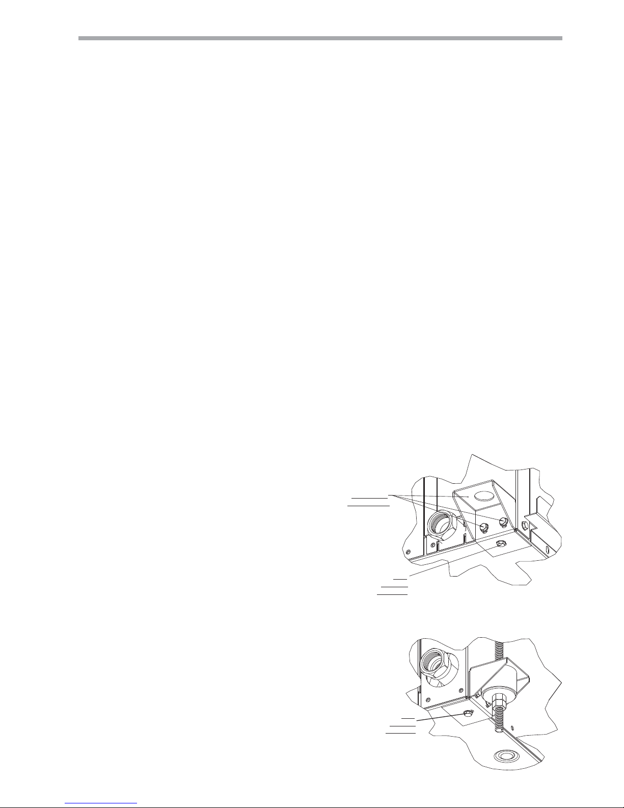
Mounting Horizontal Units
Horizontal units have 4 hanger brackets partially
attached at the factory, one at each corner. Enclosed
within the unit there is a hanger kit hardware bag
containing vibration isolation grommets, washers,
screws and a hanger installation instruction page. One
additional screw from the hardware bag must be added
to each hanger bracket before unit installation.Tighten
each screw to 75 in-lbs (8.5 Nm). See Figure 1. Refer
to the hanger installation instruction page contained
in the hardware bag for details of fi nal hanger bracket
attachment and unit suspension. See Figure 1a.
Use four (4) fi eld supplied threaded rods and factory
provided vibration isolators to suspend the unit. Safely
lift the unit into position supporting the bottom of the
unit. Ensure the top of the unit is not in contact with
any external objects. Connect the top end of the 4
all-thread rods, slide rods through the brackets and
grommet then assemble washers and double nuts at
each rod. Ensure that the unit is approximately level
and that the threaded rod extends past the nuts.
Pitch the unit toward the drain as shown in Figure 2
to improve the condensate drainage. On small units
(less than 8.8 kW) ensure that unit pitch does not cause
condensate leaks inside the cabinet.
VIEW CONDENSATE END
BEFORE GROMMET AND HARDWARE
(Unit pictured for hanger bracket reference).
(Drain hardware may vary per unit model)
INSTALLED
AT FACTORY
ADD
BEFORE
HANGING
VIEW WATER CONNECTION END
FULLY ASSEMBLED
(Unit pictured for hanger bracket reference)
(Water hardware may vary per unit model)
ADD
BEFORE
HANGING
Figure 1a:
Figure 1: Hanger Bracket
CLIMATEMASTER WATER-SOURCE HEAT PUMPS
8
ClimateMaster Water-Source Heat Pumps
Tranquility 16 (TC) Series
Rev.: 25 July, 2017
Air Coil - To obtain maximum performance, the air coil
should be cleaned before start-up. A 10% solution of
dishwasher detergent and water is recommended for
both sides of the coil. A thorough water rinse should
follow. UV based anti-bacterial systems may damage
coated air coils.
Notice! Installation Note - Ducted Return: Many
horizontal WSHPs are installed in a return air ceiling
plenum application (above ceiling). Vertical WSHPs
are commonly installed in a mechanical room with free
return (e.g. louvered door). Therefore, fi lter rails are the
industry standard and are included on ClimateMaster
commercial heat pumps for the purposes of holding
the fi lter only. For ducted return applications, the fi lter
rail must be removed and replaced with a duct fl ange
or fi lter frame. Canvas or fl exible connectors should
also be used to minimize vibration between the unit
and ductwork.
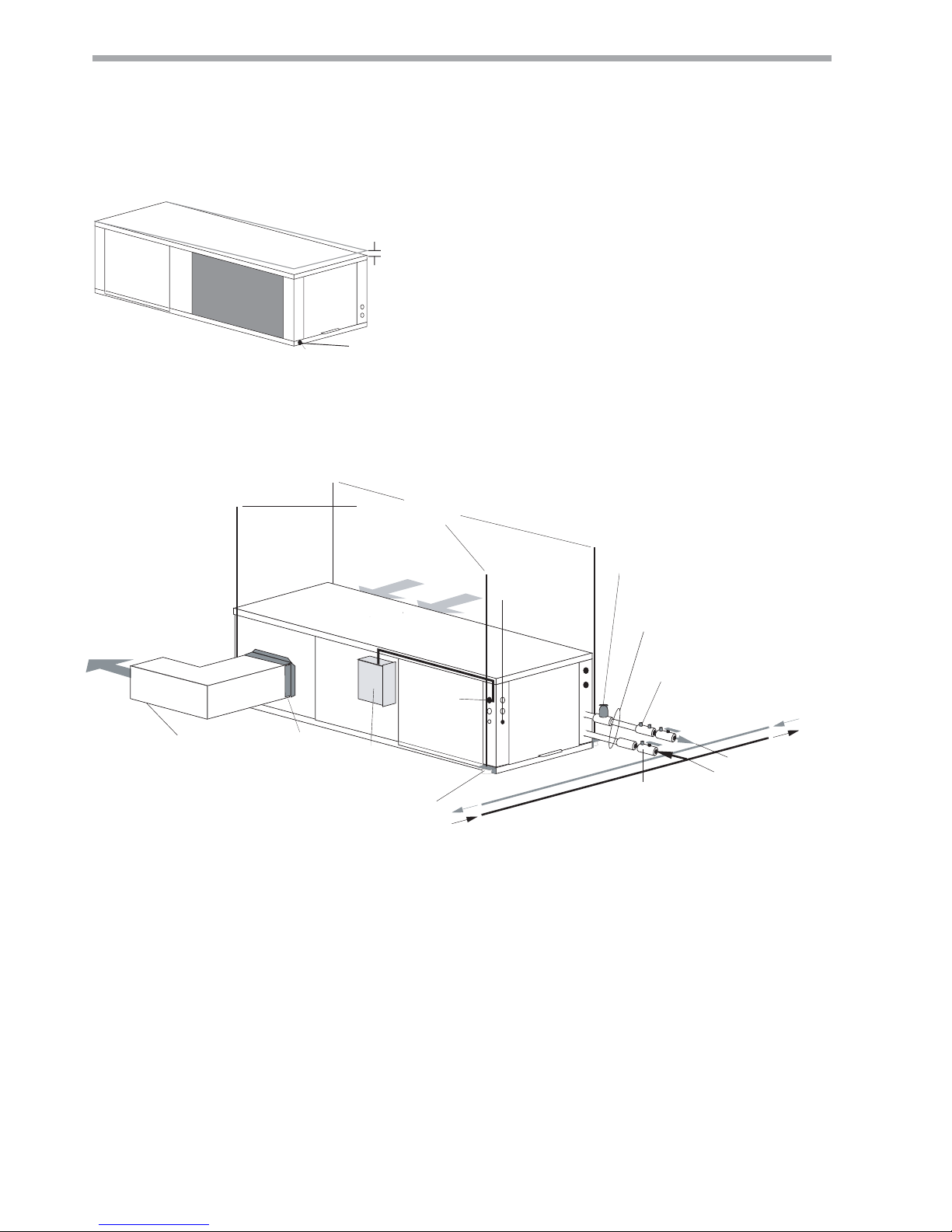
Figure 3: Typical Horizontal Unit Installation
(by others)
Thermostat
Wiring
Water In
Water Out
Optional Balancing Valve
Stainless steel braid hose
with integral "J" swivel
Building
Loop
Power Wiring
Return Air
Supply Air
Unit Hanger
Ball Valve with optional
integral P/T plug
3/8" [10mm] threaded rods
Unit Power
Flexible Duct
Connector
Insulated supply duct with
at least one 90 deg elbow
to reduce noise
Unit Power
Disconnect
(by others)
Optional Low Pressure Drop Water
Control Valve
(can be internally mounted
on some models)
Figure 2: Horizontal Unit Pitch
6.4mm pitch
for drainage
Drain Connection
THE SMART SOLUTION FOR ENERGY EFFICIENCY
9
climatemaster.com
Tranquility 16 (TC) Series
Rev.: 25 July, 2017
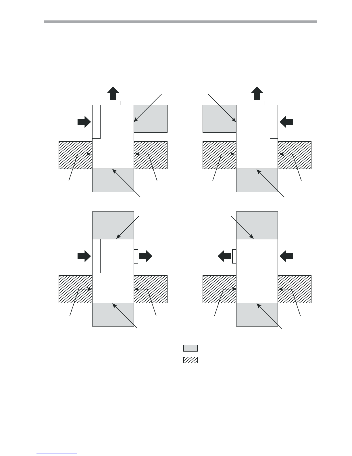
ASPASPASP
CCPCCP
ASP
ASP ASP
BSP
BSP BSP
BSP
ASP ASP
Return
Air Flow
Left Return Back Discharge
Supply
Air Flow
Air Coil
Right Return Back Discharge
Supply
Air Flow
Air Coil
Return
Air Flow
Return
Air Flow
Right Return Straight Discharge
Supply
Air Flow
Supply
Air Flow
Air Coil
Return
Air Flow
Left Return Straight Discharge
= mandatory 61 cm service access
= (optional) additional 61 cm service access
Air Coil
Front Front
FrontFront
CCP CCP
Notes:
1. While clear access to all removable panels is not required,
installer should take care to comply with all building codes
and allow adequate clearance for future fi eld service.
2. CCP and BSP requires 61 cm service access.
3. Blower service access is through back panel on straight
discharge units or through panel opposite air coil on back
discharge units.
4. ASP are removable panels that provide additional access to
the units interior. Clear access to ASP panels is not required
and they are not to be used in place of the mandatory CCP
and BSP panels.
Legend:
CCP = Control/Compressor Access Panel
BSP = Blower Service Panel
ASP = Additional Service Panel (not required)
CLIMATEMASTER WATER-SOURCE HEAT PUMPS
10
ClimateMaster Water-Source Heat Pumps
Tranquility 16 (TC) Series
Rev.: 25 July, 2017
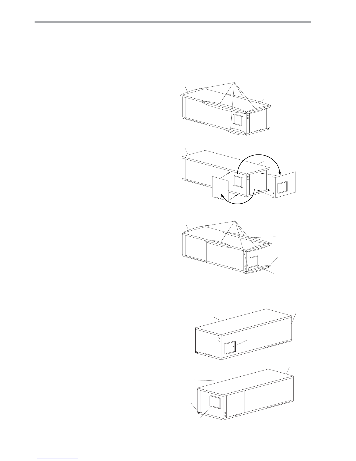
Field Conversion of Air Discharge
Overview -
Horizontal units can be fi eld converted
between straight (side) and back (end) discharge using
the instructions below.
Note: It is not possible to fi eld convert return air
between left or right return models due to the
necessity of refrigeration copper piping changes.
Preparation - Field conversion must be completed
on the ground. If the unit is already hung it should be
taken down for the fi eld conversion. Place in a well-
lighted area. Conversion should only be attempted by
a qualifi ed service technician.
Side to Back Discharge Conversion
1. Remove back panel and side access panel
2. Loosen 2 motor slide nuts, raise motor slide
assembly and remove belt and motor sheave.
3. Remove blower sheave. Remove motor bolts and
carefully remove motor.
4. Remove 2 motor clips and reattach to opposite
side.
5. Unbolt (3 per side) complete housing assembly.
6. Rotate complete assembly into new position.
Locate over mounting holes in base, reattach using
3 bolts per side.
7. Mount motor, motor sheave, blower sheave and
belt. Make sure wires are not pinched and not over
sharp edges. Adjust motor downward to tighten
belt. Raise or lower motor slide assembly with
adjusting bolt and retighten 2 slide nuts. Check
for correct tension (See Tensioning V-Belt Drives
page). Rewire motor (at contactor) for correct
rotation. Spin blower wheel to ensure wheel is not
obstructed.
8. Replace 2 panels.
Back to Side Discharge Conversion - If the discharge
is changed from back to side, use above instruction
noting that illustrations will be reversed.
Left vs. Right Return - It is not possible to fi eld convert
return air between left or right return models due to
the necessity of refrigeration copper piping changes.
However, the conversion process of side to back or
back to side discharge for either right or left return
confi guration is the same. In some cases, it may be
possible to rotate the entire unit 180 degrees if the
return air connection needs to be on the opposite side.
Note that rotating the unit will move the piping to the
other end of the unit.
Water
Connection End
Return Air
Remove Screws
Water
Connection End
Return Air
Rotate
Move to Side
Side Discharge
Return Air
Water
Connection End
Discharge Air
Drain
Back Discharge
Replace Screws
Figure 5: Right Return Side to Back
Figure 4: Left Return Side to Back
Water
Connection End
Supply Duct
Return Air
Water
Connection End
Drain
Return Air
Discharge Air
Side Discharge
Back Discharge
THE SMART SOLUTION FOR ENERGY EFFICIENCY
11
climatemaster.com
Tranquility 16 (TC) Series
Rev.: 25 July, 2017
Horizontal Installation
Condensate Piping - Horizontal Units - A condensate
drain line must be installed and pitched away for the
unit to allow for proper drainage. This connection must
meet all local plumbing/building codes.
Pitch the unit toward the drain as shown in Figure 2 to
improve the condensate drainage. On small units (less
than 8.8 kW), ensure that unit pitch does not cause
condensate leaks inside the cabinet.
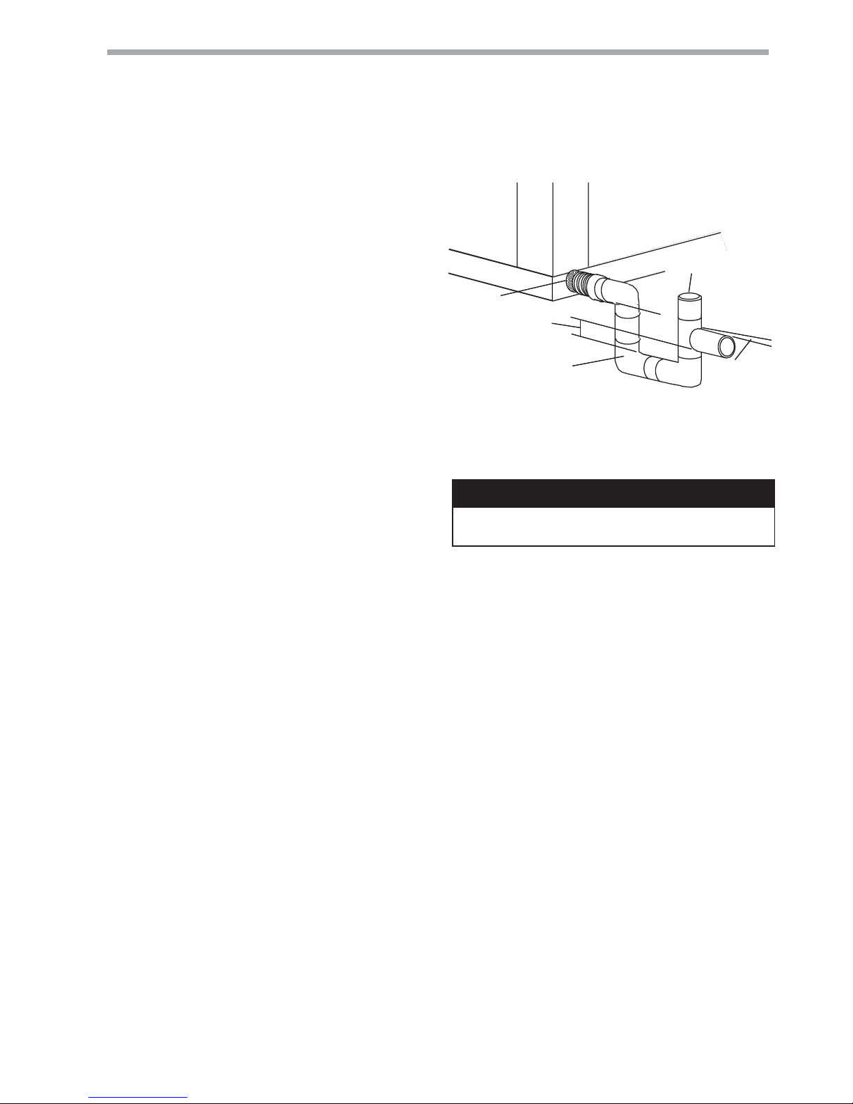
Install condensate trap at each unit with the top of
the trap positioned below the unit condensate drain
connection as shown in Figure 6. Design the depth of
the trap (water-seal) based upon the amount of ESP
capability of the blower (where 51mm of ESP capability
requires 51mm of trap depth). As a general rule, 38mm
trap depth is the minimum.
Each unit must be installed with its own individual trap
and connection to the condensate line (main) or riser.
Provide a means to fl ush or blow out the condensate
line. DO NOT install units with a common trap and/or
vent.
Always vent the condensate line when dirt or air
can collect in the line or a long horizontal drain line
is required. Also vent when large units are working
against higher external static pressure than other units
connected to the same condensate main since this may
cause poor drainage for all units on the line. WHEN A
VENT IS INSTALLED IN THE DRAIN LINE, IT MUST BE
LOCATED AFTER THE TRAP IN THE DIRECTION OF
THE CONDENSATE FLOW.
*3/4" FPT
Trap Depth
38mm
Min
38mm
21mm per m
drain slope
3/4" PVC or
Copper by others
Vent
* Some units include a painted drain
connection. Using a threaded pipe or
similar device to clear any excess paint
accumulated inside this fitting may
ease final drain line installation.
Figure 6: Horizontal Condensate Connection
CAUTION! Ensure condensate line is pitched toward drain
21mm per m of run.
CAUTION!

CLIMATEMASTER WATER-SOURCE HEAT PUMPS
12
ClimateMaster Water-Source Heat Pumps
Tranquility 16 (TC) Series
Rev.: 25 July, 2017
Duct System Installation - Proper duct sizing and
design is critical to the performance of the unit. The
duct system should be designed to allow adequate
and even airfl ow through the unit during operation.
Air fl ow through the unit MUST be at or above the
minimum stated airfl ow for the unit to avoid equipment
damage. Duct systems should be designed for quiet
operation. Refer to Figure 3 for horizontal duct system
details or Figure 8 for vertical duct system details. A
fl exible connector is recommended for both discharge
and return air duct connections on metal duct systems
to eliminate the transfer of vibration to the duct
system. To maximize sound attenuation of the unit
blower, the supply and return plenums should include
internal fi berglass duct liner or be constructed from
ductboard for the fi rst few feet. Application of the unit
to uninsulated ductwork in an unconditioned space is
not recommended, as the unit’s performance may be
adversely affected.
At least one 90° elbow should be included in the
supply duct to reduce air noise. If air noise or excessive
air fl ow is a problem, the blower speed can be
changed. For airfl ow charts, consult submittal data for
the series and model of the specifi c unit.
If the unit is connected to existing ductwork, a
previous check should have been made to ensure that
the ductwork has the capacity to handle the airfl ow
required for the unit. If ducting is too small, as in the
replacement of a heating only system, larger ductwork
should be installed. All existing ductwork should be
checked for leaks and repaired as necessary.
Duct System Installation
THE SMART SOLUTION FOR ENERGY EFFICIENCY
13
climatemaster.com
Tranquility 16 (TC) Series
Rev.: 25 July, 2017
Vertical Installation
Vertical Unit Location
Units are not designed for outdoor installation. Locate
the unit in an INDOOR area that allows enough space
for service personnel to perform typical maintenance
or repairs without removing unit from the mechanical
room/closet. Vertical units are typically installed in a
mechanical room or closet. Never install units in areas
subject to freezing or where humidity levels could
cause cabinet condensation (such as unconditioned
spaces subject to 100% outside air). Consideration
should be given to access for easy removal of the fi lter
and access panels. Provide suffi cient room to make
water, electrical, and duct connection(s).
If the unit is located in a confi ned space, such as a
closet, provisions must be made for return air to freely
enter the space by means of a louvered door, etc. Any
access panel screws that would be diffi cult to remove
after the unit is installed should be removed prior to
setting the unit. Refer to Figures 7 and 8 for typical
installation illustrations. Refer to unit submittal data or
engineering design guide for dimensional data.
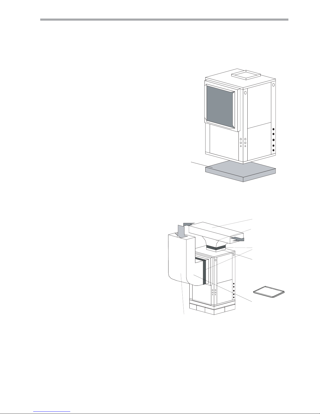
1. Install the unit on a piece of rubber, neoprene or
other mounting pad material for sound isolation.
The pad should be at least 10mm to 13mm in
thickness. Extend the pad beyond all four edges
of the unit.
2. Provide adequate clearance for fi lter replacement
and drain pan cleaning. Do not block fi lter access
with piping, conduit or other materials. Refer to
unit submittal data or engineering design guide
for dimensional data.
3. Provide access for fan and fan motor maintenance
and for servicing the compressor and coils without
removing the unit.
4. Provide an unobstructed path to the unit within
the closet or mechanical room. Space should be
suffi cient to allow removal of the unit, if necessary.
5.
In limited side access installations, pre-removal of the
control box side mounting screws will allow control
box removal for future servicing (TC units only).
6. Provide access to water valves and fi ttings
and screwdriver access to the unit side panels,
discharge collar and all electrical connections.
Flexible canvas duct
connector to reduce
noise and vibration
Use turning vanes in
supply transition
Internally insulate supply
duct fRUILUVWP each way
to reduce noise
Internally insulate return
transition duct to reduce noise
Rounded return
transition
5HPRYHVXSSO\GXFW
IODQJHVIURPLQVLGHEORZHU
FRPSDUWPHQWDQGLQVWDOO
on supply air opening of
unit. Do not use a supply
DLUSOHQXPGXFWVPDOOHU
than the size of the supply
duct flanges.
Figure 8: Typical Vertical Unit Installation Using
Ducted Return Air
Air Pad or extruded
polystyrene insulation board
Figure 7: Typical Vertical Unit Mounting
CLIMATEMASTER WATER-SOURCE HEAT PUMPS
14
ClimateMaster Water-Source Heat Pumps
Tranquility 16 (TC) Series
Rev.: 25 July, 2017
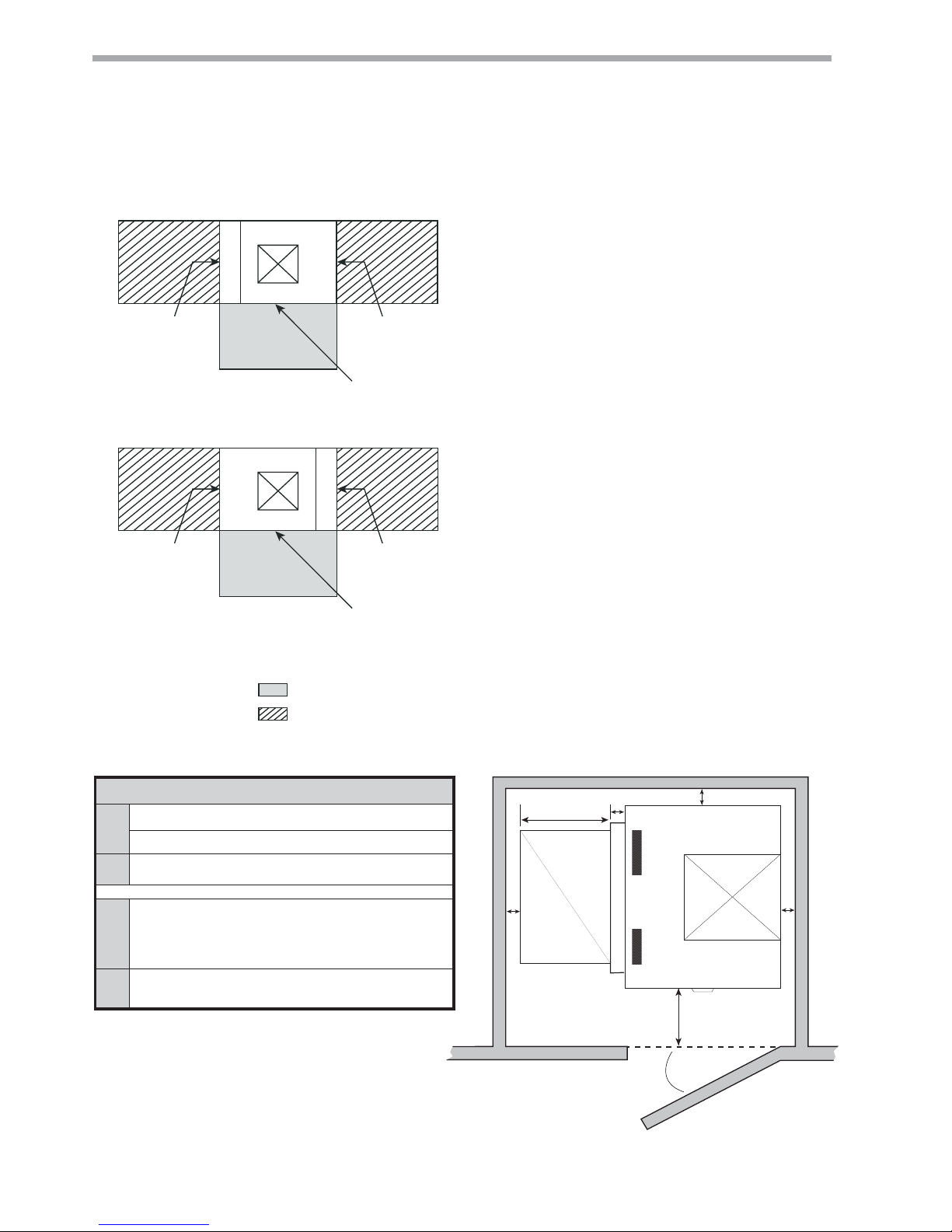
Left Return
Right Return
= mandatory 61 cm service access
= (optional) additional 61 cm service access
ASPASP
Air Coil
Front
CCP and BSP
Supply Air
Opening
ASPASP
Air Coil
Front
CCP and BSP
Supply Air
Opening
Legend:
CCP = Control/Compressor Access Panel
BSP = Blower Service Panel
ASP = Additional Service Panel (not required)
Notes:
1. While clear access to all removable panels is not required,
installer should take care to comply with all building codes
and allow adequate clearance for future fi eld service.
2. Front & Side access is preferred for service access. However,
all components may be serviced from the front access panel
if side access is not available. (Except on units with front
return air).
3. ASP are removable panels that provide additional access to
the units interior. Clear access to ASP panels is not required
and they are not to be used in place of the mandatory CCP
and BSP panels.
4. Top supply air is shown, the same clearances apply to
bottom supply air units.
5. Front return units (not shown) require front access for
controls/compressor and left side access for blower.
Recommended Minimum Installation Clearances for Vertical Units*
2.5
cm
Back of unit
Side opposite return air
15.2
cm
Front if hard piped
Return Air Side
2.5
cm
Ducted return
- ‡ Add for duct width
- † Add 5.0 cm for 2.5 cm fi lter frame/rail or 7.6 cm for 5.0 cm
fi lter frame/rail
Free (open) return - calculate required dimension for a maximum
velocity of 3.0 m/s
*Field installed accessories (hoses, air cleaners, etc.) may require additional space.
Top supply air is shown, the same clearances apply to bottom supply air units.
Air Coil Side
Front
‡
†
2.5
cm
15.2
cm
2.5
cm
2.5
cm
THE SMART SOLUTION FOR ENERGY EFFICIENCY
15
climatemaster.com
Tranquility 16 (TC) Series
Rev.: 25 July, 2017
Vertical Installation
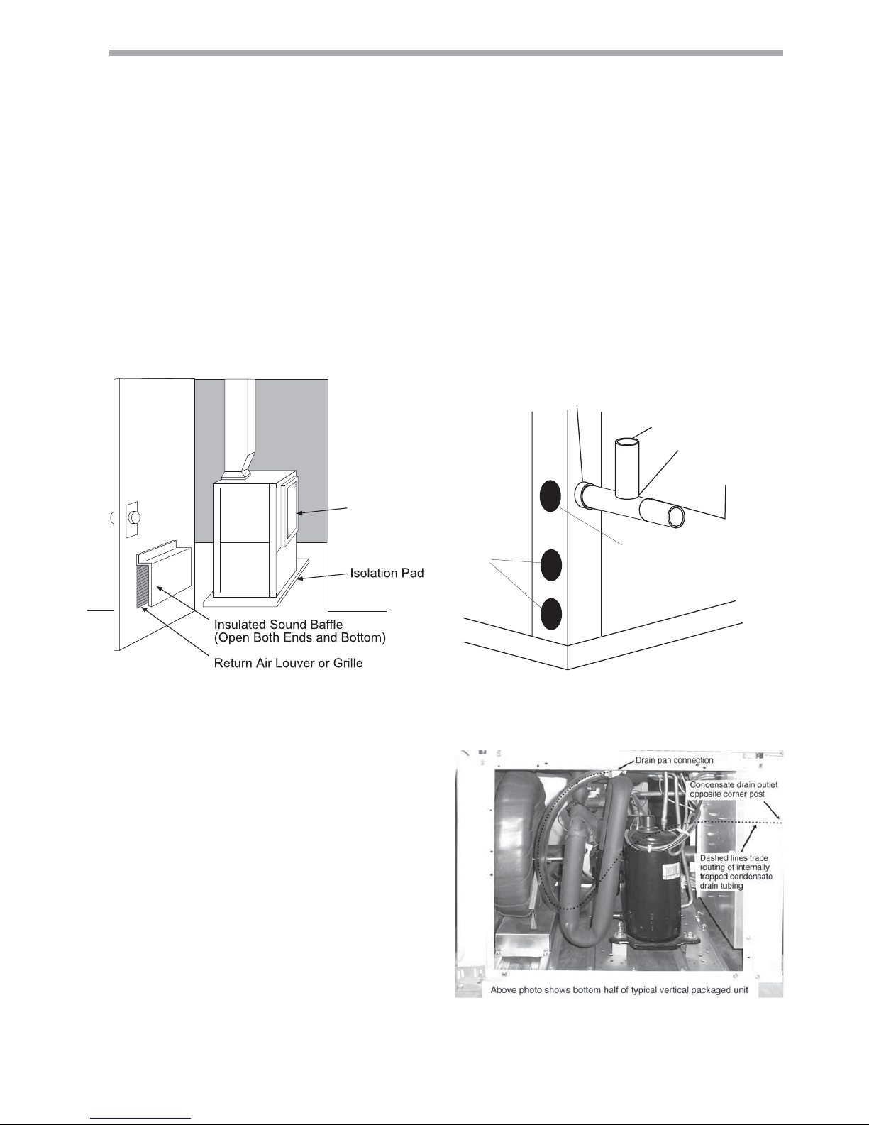
Sound Attenuation for Vertical Units - Sound
attenuation is achieved by enclosing the unit within
a small mechanical room or a closet. Additional
measures for sound control include the following:
1. Mount the unit so that the return air inlet is 90°
to the return air grille. Refer to Figure 9. Install a
sound baffl e as illustrated to reduce line-of sight
sound transmitted through return air grilles.
2. Mount the unit on a rubber or neoprene isolation
pad to minimize vibration transmission to the
building structure.
Condensate Piping for Vertical Units - A condensate
line must be installed and pitched away from the unit to
allow for proper drainage. This connection must meet
all local plumbing/building codes. Vertical units utilize
a condensate hose inside the cabinet as a trapping
loop; therefore an external trap is not necessary. Figure
10a shows typical condensate connections. Figure
10b illustrates the internal trap for a typical vertical
heat pump. Each unit must be installed with its own
individual vent (where necessary) and a means to fl ush
or blow out the condensate drain line. Do not install
units with a common trap and/or vent.
Vent
*3/4" FPT
3/4" PVC
Alternate
Condensate
Location
Water
Connections
* Some units include a painted drain connection. Using a
threaded pipe or similar device to clear any excess paint
accumulated inside this fitting may ease final drain line installation.
1/8" per foot
slope to drain
Figure 10a: Vertical Condensate Drain
Figure 10b: Vertical Internal Condensate Trap
Return
Air Inlet
Figure 9: Vertical Sound Attenuation
Units with clear plastic drain lines should have regular maintenance
(as required) to avoid buildup of debris, especially in new
construction.
CLIMATEMASTER WATER-SOURCE HEAT PUMPS
16
ClimateMaster Water-Source Heat Pumps
Tranquility 16 (TC) Series
Rev.: 25 July, 2017
Piping Installation
Installation of Supply and Return Piping
Follow these piping guidelines.
1. Install a drain valve at the base of each supply and
return riser to facilitate system fl ushing.
2. Install shut-off / balancing valves and unions at
each unit to permit unit removal for servicing.
3. Place strainers at the inlet of each system
circulating pump.
4. Select the proper hose length to allow slack
between connection points. Hoses may vary in
length by +2% to -4% under pressure.
5. Refer to Table 1. Do not exceed the minimum
bend radius for the hose selected. Exceeding
the minimum bend radius may cause the hose to
collapse, which reduces water fl ow rate. Install an
angle adapter to avoid sharp bends in the hose
when the radius falls below the required minimum.
Insulation is not required on loop water piping except
where the piping runs through unheated areas, outside
the building or when the loop water temperature is
below the minimum expected dew point of the pipe
ambient conditions. Insulation is required if loop water
temperature drops below the dew point (insulation is
required for ground loop applications in most climates).
Pipe joint compound is not necessary when Tefl on
®
thread tape is pre-applied to hose assemblies or
when fl ared-end connections are used. If pipe joint
compound is preferred, use compound only in small
amounts on the external pipe threads of the fi tting
adapters. Prevent sealant from reaching the fl ar ed
surfaces of the joint.
Note: When antifreeze is used in the loop, ensure
that it is compatible with the Tefl on tape or pipe
joint compound that is applied.
Maximum allowable torque for brass fi ttings is 41 N-m.
If a torque wrench is not available, tighten fi nger-tight
plus one quarter turn. Tighten steel fi ttings
as necessary.
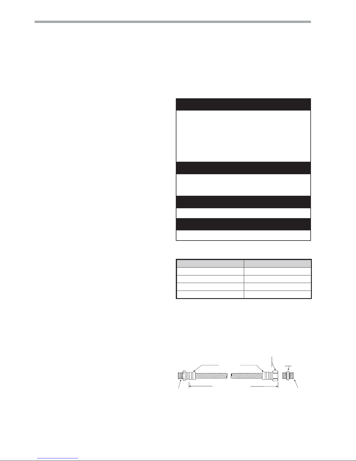
Optional pressure-rated hose assemblies designed
specifi cally for use with ClimateMaster units are
available. Similar hoses can be obtained from alternate
suppliers. Supply and return hoses are fi tted with
swivel-joint fi ttings at one end to prevent kinking during
installation.
Refer to Figure 11 for an illustration of a typical supply/
return hose kit. Adapters secure hose assemblies to
the unit and risers. Install hose assemblies properly and
check regularly to avoid system failure and reduced
service life.
A backup wrench is required when tightening water
connections to prevent water line damage for TC Series
equipment. TS Series equipment has water connections
secured to the corner post.
Table 1: Metal Hose Minimum Bend Radii
Hose Diameter Minimum Bend Radii
12.7mm 6.4cm
19.1mm 10.2cm
25.4mm 14cm
31.8mm 17.1cm
NOTICE! Do not allow hoses to rest against
structural building components. Compressor
vibration may be transmitted through the hoses to
the structure, causing unnecessary noise complaints.
Figure 11: Supply/Return Hose Kit
Rib Crimped
Length
(0.6m Length Standard)
Swivel
Brass
Fitting
Brass
Fitting
MPT
MPT
CAUTION! Corrosive system water requires corrosion
resistant fi ttings and hoses, and may require water
treatment.
CAUTION! Do not bend or kink supply lines or hoses.
CAUTION!
CAUTION!
CAUTION!
CAUTION! Piping must comply with all applicable codes.
WARNING! Polyolester Oil, commonly known as POE
oil, is a synthetic oil used in many refrigeration systems
including those with HFC-410A refrigerant. POE oil, if it
ever comes in contact with PVC or CPVC piping, may
cause failure of the PVC/CPVC. PVC/CPVC piping should
never be used as supply or return water piping with water
source heat pump products containing HFC-410A as
system failures and property damage may result.
WARNING!
 Loading...