

ClimateMaster TMW036, TMW120, TMW060, TMW340, TMW170 Installation Operation & Maintenance
Table of Contents
Model Nomenclature 3
Storage 5
Pre-Installation 5
Physical Data 6
Dimensional Data 7
Unit Installation 9
Piping Installation 9
Load Plumbing Installation 10
Water Loop Applications 11
Open Loop - Ground Water Systems 12
Water Quality Standards 12
Ground Loop Applications 14
Electrical - Line Voltage 15
Electrical - Low Voltage Wiring 16
Electrical - Accessories 17
Water Valve Wiring 17
TMW Series Wiring Diagram Matrix 18
Electrical Wiring Schematics 19
CXM/DXM Controls 25
CXM/DXM Safety Control Reset 28
Unit Commissioning and Operating Conditions 29
Piping System Cleaning & Flushing 30
Unit and System Checkout Procedure 31
Start Up Procedure 32
Preventive Maintenance 33
Warranties 34
Refrigeration Troubleshooting Form 35
Revision History 36
Tranquility® Modular
Water-to-Water
(TMW) Series
Water-Source Heat Pumps
50Hz-HFC-410A
Installation, Operation &
Maintenance
97B0059N05
Rev.: 02 January, 2013

CLIMATEMASTER WATER-SOURCE HEAT PUMPS
2
ClimateMaster Water-Source Heat Pumps
Tranquility® Modular Water-to-Water (TMW )Series
Rev.: 02 January, 2013
This Page Intentionally Left Blank
THE SMART SOLUTION FOR ENERGY EFFICIENCY
3
climatemaster.com
Tranquility® Modular Water-to-Water (TMW )Series
Rev.: 02 January, 2013
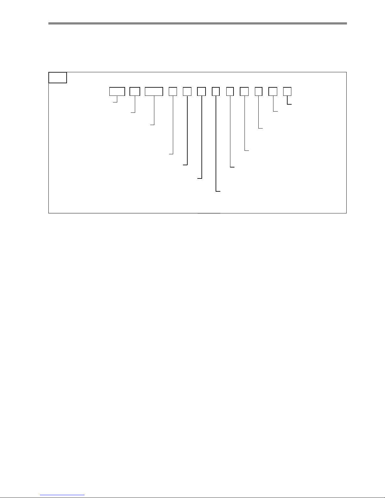
Model Nomenclature
TM W A FU 1 0 C 0 C S
1 2 3 4 5 6 7
8
9101112131415
TM = TRANQUILITY® MEDIUM TEMPERATURE
MODEL TYPE
W = WATER TO W A TER HEA T PUMP
CONFIGURATION
UNIT SIZE
036
060
120
170
340
REVISION LEVEL
A = CURRENT
VOL TAGE
CONTROLS
1 = COMMERCIAL EXTENDED RANGE
CABINET INSULATION
2 = COMMERCIAL EXTENDED RANGE w/ULTRA QUIET
HOT WA TER GENERA T OR OPTIONS
C = Copper
SOURCE WA TER COIL OPTIONS
N = Cupro-nickel
C = Copper
LOAD WA TER COIL OPTIONS
N = Cupro-nickel
S = STANDARD
Z17
0 = N O NE (036-340)
2 =HOT WATER GENERATOR COIL (036-120 ONLY)
RESERVED - FUTURE OPTIONS
0 = NONE
V = 220-240/50/1
}
F = CXM
G = DXM
H = CXM w/LON
J = DXM w/LON
T = CXM w/MPC
U = DXM w/MPC
CE
MARKED
FOR EUROPE
340
U = 380-420/50/3

CLIMATEMASTER WATER-SOURCE HEAT PUMPS
4
ClimateMaster Water-Source Heat Pumps
Tranquility® Modular Water-to-Water (TMW )Series
Rev.: 02 January, 2013
General Information
WARNING!
WARNING!
CAUTION!
CAUTION! To avoid equipment damage, DO NOT use
these units as a source of heating or cooling during the
construction process. The mechanical components and
fi lters will quickly become clogged with construction dirt
and debris, which may cause system damage.
WARNING! To avoid the release of refrigerant into the
atmosphere, the refrigerant circuit of this unit must be
serviced only by technicians who meet local, state, and
federal profi ciency requirements.
Safety
Warnings, cautions, and notices appear throughout this
manual. Read these items carefully before attempting
any installation, service, or troubleshooting of the
equipment.
DANGER: Indicates an immediate hazardous situation,
which if not avoided will result in death or serious
injury. DANGER labels on unit access panels must be
observed.
WARNING: Indicates a potentially hazardous situation,
which if not avoided could result in death or serious
injury.
CAUTION: Indicates a potentially hazardous situation
or an unsafe practice, which if not avoided could result
in minor or moderate injury or product or property
damage.
NOTICE: Notifi cation of installation, operation, or
maintenance information, which is important, but which
is not hazard-related.
WARNING! All refrigerant discharged from this unit must
be recovered WITHOUT EXCEPTION. Technicians must
follow industry accepted guidelines and all local, state,
and federal statutes for the recovery and disposal of
refrigerants. If a compressor is removed from this unit,
refrigerant circuit oil will remain in the compressor. To
avoid leakage of compressor oil, refrigerant lines of the
compressor must be sealed after it is removed.

THE SMART SOLUTION FOR ENERGY EFFICIENCY
5
climatemaster.com
Tranquility® Modular Water-to-Water (TMW )Series
Rev.: 02 January, 2013
Inspection
Upon receipt of the equipment, carefully check the
shipment against the bill of lading. Make sure all units
have been received. Inspect the carton or crating of
each unit, and inspect each unit for damage. Assure
the carrier makes proper notation of any shortages or
damage on all copies of the freight bill and completes a
common carrier inspection report. Concealed damage
not discovered during unloading must be reported to
the carrier within 15 days of receipt of shipment. If not
fi led within 15 days, the freight company can deny the
claim without recourse. Note: It is the responsibility of
the purchaser to fi le all necessary claims with the carrier.
Notify the ClimateMaster Traffi c Department of all
damage within fi fteen (15) days of shipment.
Storage
Equipment should be stored in its original packaging in
a clean, dry area. Store units in an upright position at all
times. Do not stack TMW170 or 340. The stack limit for
TMW036, 060 and 120 is three.
Unit Protection
Cover units on the job site with either shipping
packaging, vinyl fi lm, or an equivalent protective
covering. Cap the open ends of pipes stored on the
job site. In areas where painting, plastering, and/or
spraying has not been completed, all due precautions
must be taken to avoid physical damage to the units and
contamination by foreign material. Physical damage and
contamination may prevent proper start-up and may
result in costly equipment clean-up.
Examine all pipes, fi ttings, and valves before installing
any of the system components. Remove any dirt or trash
found in or on these components.
Pre-Installation
Installation, Operation, and Maintenance instructions
are provided with each unit.. The installation site chosen
should include adequate service clearance around the
unit. Before unit start-up, read all manuals and become
familiar with the unit and its operation. Thoroughly check
the system before operation.
Prepare units for installation as follows:
1. Compare the electrical data on the unit nameplate
with ordering and shipping information to verify that
the correct unit has been shipped.
2. Keep the cabinet covered with the shipping
packaging until installation is complete and all
plastering, painting, etc. is fi nished.
3. Verify r efrigerant tubing is fr ee of kinks or dents and
that it does not touch other unit components.
4. Inspect all electrical connections. Connections must
be clean and tight at the terminals.
CAUTION!
CAUTION!
CAUTION!
CAUTION! CUT HAZARD - Failure to follow this caution
may result in personal injury. Sheet metal parts may have
sharp edges or burrs. Use care and wear appropriate
protective clothing, safety glasses and gloves when
handling parts and servicing heat pumps.
CAUTION! DO NOT store or install units in corrosive
environments or in locations subject to temperature or
humidity extremes (e.g., attics, garages, rooftops, etc.).
Corrosive conditions and high temperature or humidity can
signifi cantly reduce performance, reliability, and service life.
Always move and store units in an upright position. Tilting
units on their sides may cause equipment damage.
CAUTION! All three phase scroll compressors must have
direction of rotation verifi ed at start-up. Verifi cation is
achieved by checking compressor Amp draw. Amp draw
will be substantially lower compared to nameplate values.
Additionally, reverse rotation results in an elevated sound
level compared to correct rotation. Reverse rotation will
result in compressor internal overload trip within several
minutes. Verify compressor type before proceeding.
CLIMATEMASTER WATER-SOURCE HEAT PUMPS
6
ClimateMaster Water-Source Heat Pumps
Tranquility® Modular Water-to-Water (TMW )Series
Rev.: 02 January, 2013
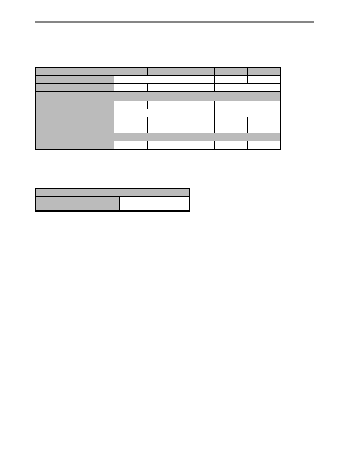
Unit Physical Data
Model 036 060 120 170 340
Compressor (qty) Scroll (1) Scroll (2) Scroll (1) Scroll (2)
Factory Charge HFC-410A kg per circuit 2.04 2.83 6.8
Water Connection Size
Source/Load (in) 3/4 1 1-1/2 2
Hot Water Generator FPT (in)
½
N/A
Weight - Operating kg 158 163 329 329 604
Weight - Packaged kg 169 175 349 347 608
Water Volume (Source)
Liters 3.64 5.04 10.02 13.27 25.44
Dual isolated compressor mounting
Balanced port expansion valve (TXV)
Insulated Source and Load Water Coils standard
Insulated Refrigerant Circuit standard
Compressor on (green) and fault (red) light
FPT - Female Pipe Thread
Unit Maximum Water Working Pressure
Options Max Working Pressure [kPa]
Base Unit 2,068
THE SMART SOLUTION FOR ENERGY EFFICIENCY
7
climatemaster.com
Tranquility® Modular Water-to-Water (TMW )Series
Rev.: 02 January, 2013
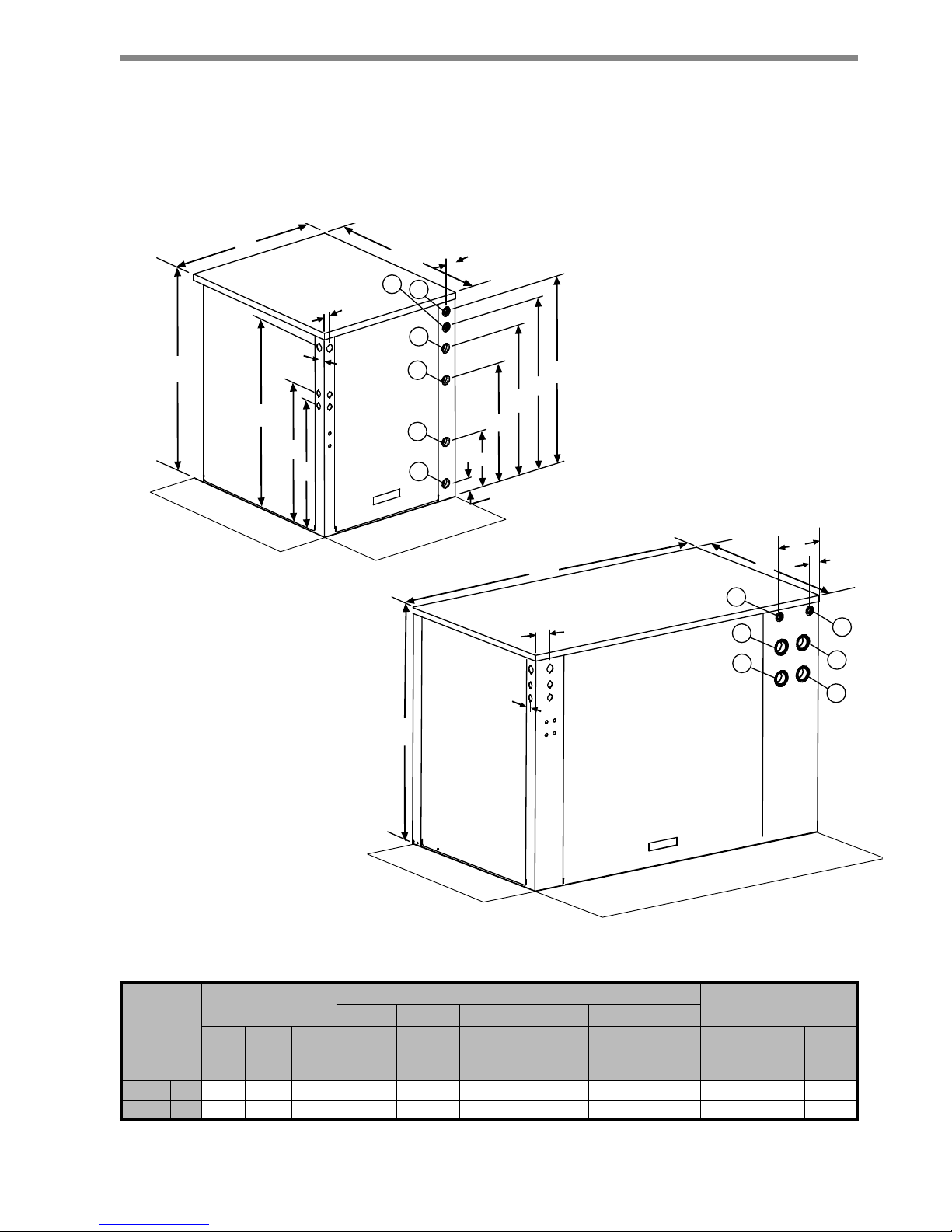
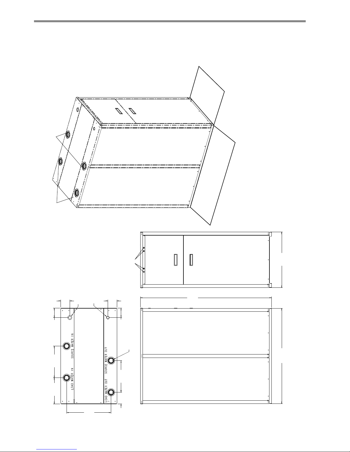
TMW036 - 120 - Unit Dimensional Data
%
&
$
0
/
.
FP
-
+
*
)
(
'
5HTXLUHG
6HUYLFH$FFHVV
2SWLRQDO
6HUYLFH$FFHVV
FP
FP
5HTXLUHG
6HUYLFH$FFHVV
2SWLRQDO
6HUYLFH$FFHVV
%
&
$
FP
FP
FP
FP
Notes:
1. Front & side access is preferred for service
access. However, all components may be
serviced from the front access panel if side
access is not available.
2. While clear access to all removable panels
is not required, installer should take care
to comply with all building codes and allow
adequate clearance for future fi eld services.
Water to
Water
Overall Cabinet
Water Connections
Electric Access Plugs
123 456
A
DepthBWidthCHeight
D
Source
(Outdoor)
Water In
E
Source
(Outdoor)
Water Out
F
Load
(Indoor)
Water In
G
Load
(Indoor)
Water Out
H
HWG
Water In
J
HWG
Water
Out
K
Low
Voltage
L
External
Pump
M
Power
Supply
036-060 cm. 77.8 64.5 83.8 6.9 23.9 49.3 62.2 70.9 77.2 53.1 58.2 78.5
120 cm. 77.8 134.4 94 64.0 64.0 76.5 76.5 88.6 88.6 75.9 81.0 87.4
CLIMATEMASTER WATER-SOURCE HEAT PUMPS
8
ClimateMaster Water-Source Heat Pumps
Tranquility® Modular Water-to-Water (TMW )Series
Rev.: 02 January, 2013
TMW170 & 340 - Unit Dimensional Data
3RZHU6XSSO\:LULQJ
[PP'RXEOH.QRFNRXW
&RQWURO:LULQJ
[PP'RXEOH.QRFNRXW
µ)37:DWHU&RQQHFWLRQV
)DXOW5XQ/LJKWV
/HIW
6LGH
9LHZ
)URQW
9LHZ
7RS
9LHZ
/RDG
6RXUFH
6LGH
5HIULJ
&LUFXLW
$FFHVV
3DQHO
)URQW
&RPSUHVVRU
$FFHVV
3DQHO
(OHFWULFDO
$FFHVV
3DQHO
+HDGHU
$FFHVV
3DQHO
7RS
1RWHV'LPHQVLRQVVKRZQLQFHQWLPHWHUVXQOHVVQRWHGRWKHUZLVH
)RUPXOWLSOHXQLWVSODFHGVLGHE\VLGHDOORZ
FPPLQLPXPIURQWDFFHVV
)37)HPDOH3LSH7KUHDG
0LQLPXP FP
5HTXLUHG6HUYLFH
$FFHVV
2SWLRQDO6LQJOH8QLW
FP $GGLWLRQDO
6HUYLFH$FFHVV

THE SMART SOLUTION FOR ENERGY EFFICIENCY
9
climatemaster.com
Tranquility® Modular Water-to-Water (TMW )Series
Rev.: 02 January, 2013
Unit Installation
Installation of Supply and Return Piping
Follow these piping guidelines.
1. Install a drain valve at the base of each supply and
return riser to facilitate system fl ushing.
2. Install shut-off / balancing valves and unions at
each unit to permit unit removal for servicing.
3. Place strainers at the inlet of each system
circulating pump.
4. Select the proper hose length to allow slack
between connection points. Hoses may vary in
length by +2% to -4% under pressure.
5. Exceeding the minimum bend radius may cause
the hose to collapse which reduces water fl ow rate.
Install an angle adapter to avoid sharp bends in
the hose when the radius falls below the required
minimum and causes a slight kink.
PIPING INSTALLATION
Insulation is not required on loop water piping
except where the piping runs through unheated
areas or outside the building or when the loop water
temperature is below the minimum expected dew
point of the pipe ambient temperature. Insulation is
required if loop water temperature drops below the
dew point.
Pipe joint compound is not necessary when Tefl on
threaded tape is pre-applied to hose assemblies or
when fl ared-end connections are used. If pipe joint
compound is preferred, use compound only in small
amounts on the pipe threads of the fi tting adapters.
Prevent sealant from reaching the fl ared surfaces of
the joint.
Note: When antifreeze is used in the loop, assure
that it is compatible with Tefl on tape or pipe joint
compound employed.
Maximum allowable torque for brass fi ttings is
41 N-m. If a torque wrench is not available, tighten
fi nger-tight plus one quarter turn. Tighten steel
fi ttings as necessary.
TMW Unit Location
These units are not designed for outdoor installation.
Locate the unit in an INDOOR area that allows
enough space for service personnel to perform typical
maintenance or repairs.
The installation of water source heat pump
units and all associated components, parts and
accessories which make up the installation shall
be in accordance with the regulations of ALL
authorities having jurisdiction and MUST conform
to all applicable codes. It is the responsibility of the
Installing Contractor to determine and comply with
ALL applicable codes and regulations.
Locate the unit in an indoor area that allows easy
removal of access panels, and has enough space for
service personnel to perform maintenance or repair.
Provide suffi cient room to make water and electrical
connections.. Any access panel screws that would be
diffi cult to remove after the unit is installed should be
removed prior to setting the unit. These units are not
approved for outdoor installation and, therefore, must
be installed inside the structure being conditioned. Do
not locate in areas where ambient conditions are not
maintained within 4-38°C.
WARNING!
WARNING! Piping must comply with all applicable codes.
WARNING!
WARNING! Do not bend or kink supply lines or hoses.
CLIMATEMASTER WATER-SOURCE HEAT PUMPS
10
ClimateMaster Water-Source Heat Pumps
Tranquility® Modular Water-to-Water (TMW )Series
Rev.: 02 January, 2013
Piping Installation
TMW Unit Load Plumbing
The applications are too varied to describe in this
document. However, some basic guidelines will be
presented. Much of the discussions on water loop
applications would be valid for the load plumbing
discussion as well. All plumbing should conform to local
codes with the following considerations:
Wide temperature variation applications such as
heating/cooling coils:
- Employ piping materials that are rated for the
maximum temperature and pressure combination.
This excludes PVC for most heating applications.
- Insure that load water fl ow in high temperature
heating applications is at least 3.2 l/m per kW
to improve performance and reduce nuisance high
pressure faults.
- DO NOT employ plastic to metal threaded joints
- Utilize a pressure tank and air separator vent system
to equalize pressure and remove air..
Swimming Pool Hot Tub Applications:
- Load side heat exchanger should be isolated with
secondary heat exchanger constructed of anticorrosion material in all chlorine/bromine fl uid
applications.
Potable Water Applications:
- Load side heat exchanger should be isolated with
secondary heat exchanger for use in potable water
systems.
- Insure load water fl ow in high temperature heating
applications is at least 3.2 l/m per kW to improve
performance and reduce nuissance to high pressure
faults.
LOAD PLUMBING INSTALLATION
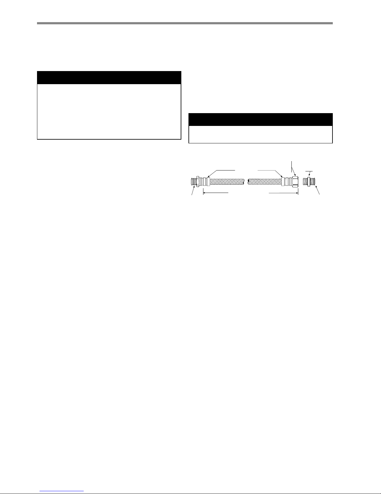
Optional pressure-rated hose assemblies designed
specifi cally for use with ClimateMaster units are available.
Similar hoses can be obtained from alternate suppliers.
Supply and return hoses are fi tted with swivel-joint fi ttings
at one end to prevent kinking during installation.
CAUTION!
CAUTION! Corrosive system water requires corrosion
resistant fi ttings and hoses and possibly water treatment.
Figure 1: Supply/Return Hose Kit
Rib Crimped
Length
(0.6m Length Standard)
Swivel
Brass
Fitting
Brass
Fitting
MPT
MPT
Note: The manufacturer strongly recommends all
piping connections, both internal and external to
the unit, be pressure tested by an appropriate
method prior to any fi nishing of the interior space
or before access to all connections is limited. Test
pressure may not exceed the maximum allowable
pressure for the unit and all components within
the water system. The manufacturer will not be
responsible or liable for damages from water leaks
due to inadequate or lack of a pressurized leak test,
or damages caused by exceeding the maximum
pressure rating during installation.
Refer to Figure 1 for an illustration of a Supply/Return
Hose Kit. Male adapters secure hose assemblies to the
unit and risers. Install hose assemblies properly and
check them regularly to avoid system failure and reduced
service life.
WARNING! Polyolester Oil, commonly known as POE
oil, is a synthetic oil used in many refrigeration systems
including those with HFC-410A refrigerant. POE oil, if it
ever comes in contact with PVC or CPVC piping, may
cause failure of the PVC/CPVC. PVC/CPVC piping should
never be used as supply or return water piping with water
source heat pump products containing HFC-410A as
system failures and property damage may result.
WARNING!
THE SMART SOLUTION FOR ENERGY EFFICIENCY
11
climatemaster.com
Tranquility® Modular Water-to-Water (TMW )Series
Rev.: 02 January, 2013
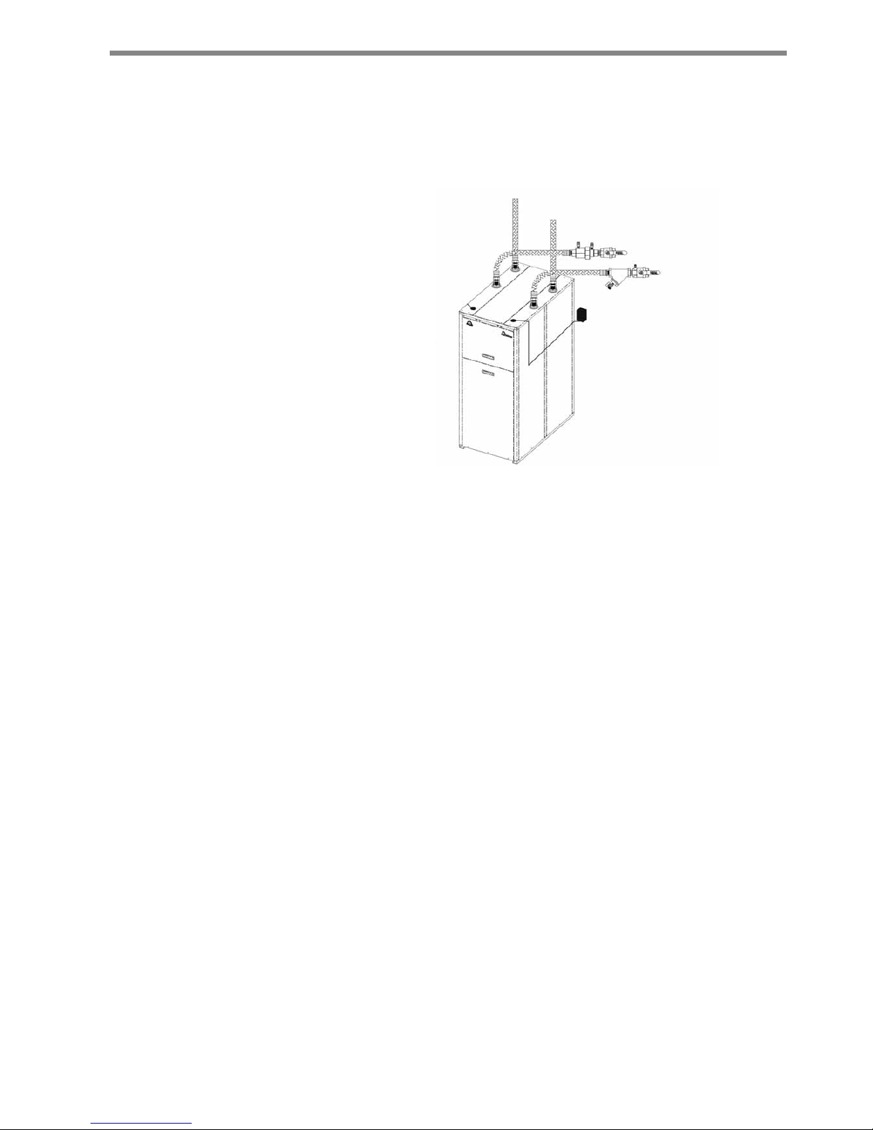
Water-Loop Heat Pump Applications
Commercial systems typically include a number of
units plumbed to a common piping system. Any unit
plumbing maintenance work can introduce air into the
piping system, therefore air elimination equipment is
a major portion of the mechanical room plumbing. In
piping systems expected to utilize water temperatures
below 10°C, 13mm closed cell insulation is required on
all piping surfaces to eliminate condensation. Metal to
plastic threaded joints should never be employed due
to their tendency to leak over time. Tefl on tape thread
sealant is recommended for FPT water connections
(commercial class) to minimize internal fouling of the heat
exchanger. Do not overtighten connections and route
piping so as not to interfere with service or maintenance
access. Hose kits are available from ClimateMaster in
Figure 2 for connection between the TMW unit and the
piping system.
The hose kits include shut off valves, P/T
plugs for performance measurement, high pressure
stainless steel braid hose, "Y" type strainer 20 mesh
(841 micron) [0.84mm]) with blowdown valve, and "J"
type swivel connection. Balancing valves to facilitate
the balancing of the system, may also be included in
the hose kit. The piping system should be fl ushed to
remove dirt, piping chips, and other foreign material
prior to operation. See Piping System Cleaning and
Flushing Procedures later in this document. The fl ow
rate is usually set between 2.4 l/m and 3.2 l/m per kW
of cooling capacity. ClimateMaster recommends 2.7
l/m per kW for most applications of water loop heat
pumps. To insure proper maintenance and servicing,
P/T ports are imperative for temperature and fl ow
verifi cation, as well as performance checks.
Cooling Tower/Boiler Systems typically utilize a
common loop maintained between 16-32°C. The use
of a closed circuit evaporative cooling tower with a
secondary heat exchanger between the tower and the
water loop is recommended. If an open type cooling
tower is used continuously, chemical treatment and
fi ltering will be necessary.
Low Water Temperature Cutout Setting
CXM or DXM Control:
When an antifreeze is selected,
the FP1 jumper (JW3) should be clipped to select the
low temperature 12°C setpoint to avoid nuisance faults.
See Figure 4: Low Water Temperature Cutout - FP1.
Figure 2: Typical Water Loop Application
Load Connections
(Hot Water/Chilled Water)
Source Connections
Power Disconnect
 Loading...