

ClimateMaster TCV072, TCV096, TCV120, TCV160, TCV192 Installation Operation & Maintenance
...
Tranquility
®
Compact
B elt Drive (TCH /V) Series
Models TCH072 - 120
TCV072 - 300
60Hz - HFC-410A
Installation, Operation
& Maintenance
97B0084N01
Revised: July 25, 2017
Table of Contents
Model Nomenclature 3
General Information 4
TCH Physical Data
TCV Physical Data
Horizontal Installation 16
TCH Field Conversion of Air Discharge 18
Vertical Installation 21
TCV Field Conversion of Air Discharge 22
TCV072-240 Field Conversion of Air Discharge 23
TCV300 Field Conversion of Air Discharge 26
TCV Field Conversion of Control Box 29
TCV Field Conversion of Water Connections 30
Vertical Condensate Installation 31
Piping Installation 32
Water-Loop Heat Pump Applications 33
Ground-Loop Heat Pump Applications 34
Ground-Water Heat Pump Applications 36
Water Quality Standards 38
Electrical - Line Voltage 39
Electrical - Power Wiring 41
Electrical - Power & Low Voltage Wiring 42
Electrical - Thermostat Wiring 44
Typical Wiring Diagram - TCH/V Units with CXM 45
CXM Controls 49
DXM Controls 50
Safety Features 52
CXM and DXM Controls 53
Blower Adjustment 54
Tensioning V-Belt Drives 55
Blower Sheave Information 56
TCH/V 072 Blower Performance 57
TCH/V 096 Blower Performance 58
TCH/V 120 Blower Performance 60
Blower Performance Data – TCV160 Standard Unit 62
Blower Performance Data – TCV192 Standard Unit 63
Blower Performance Data – TCV240 Standard Unit 64
Blower Performance Data – TCV240 Standard Unit 65
Blower Performance Data – TCV300 Standard Unit 66
Unit Starting and Operating Conditions 67
Piping System Cleaning and Flushing 68
Unit Starting and Operating Conditions 69
Unit Start-Up Procedure 70
Unit Operating Conditions 72
Start-Up Log Sheet 73
Preventive Maintenance 74
Circuit Diagram with Safety Devices 75
Functional Troubleshooting 76
Performance Troubleshooting 77
Warranty (U.S. & Canada) 79
Revision History 80
(includes unit w/WSE) 6
(includes unit w/WSE) 9

CLIMATEMASTER WATER-SOURCE HEAT PUMPS
Tranquility
Rev.: July 25, 2017
®
Compact Belt Drive (TCH/V) Series
This Page Intentionally Left Blank
2
ClimateMaster Water-Source Heat Pumps
THE SMART SOLUTION FOR ENERGY EFFICIENCY
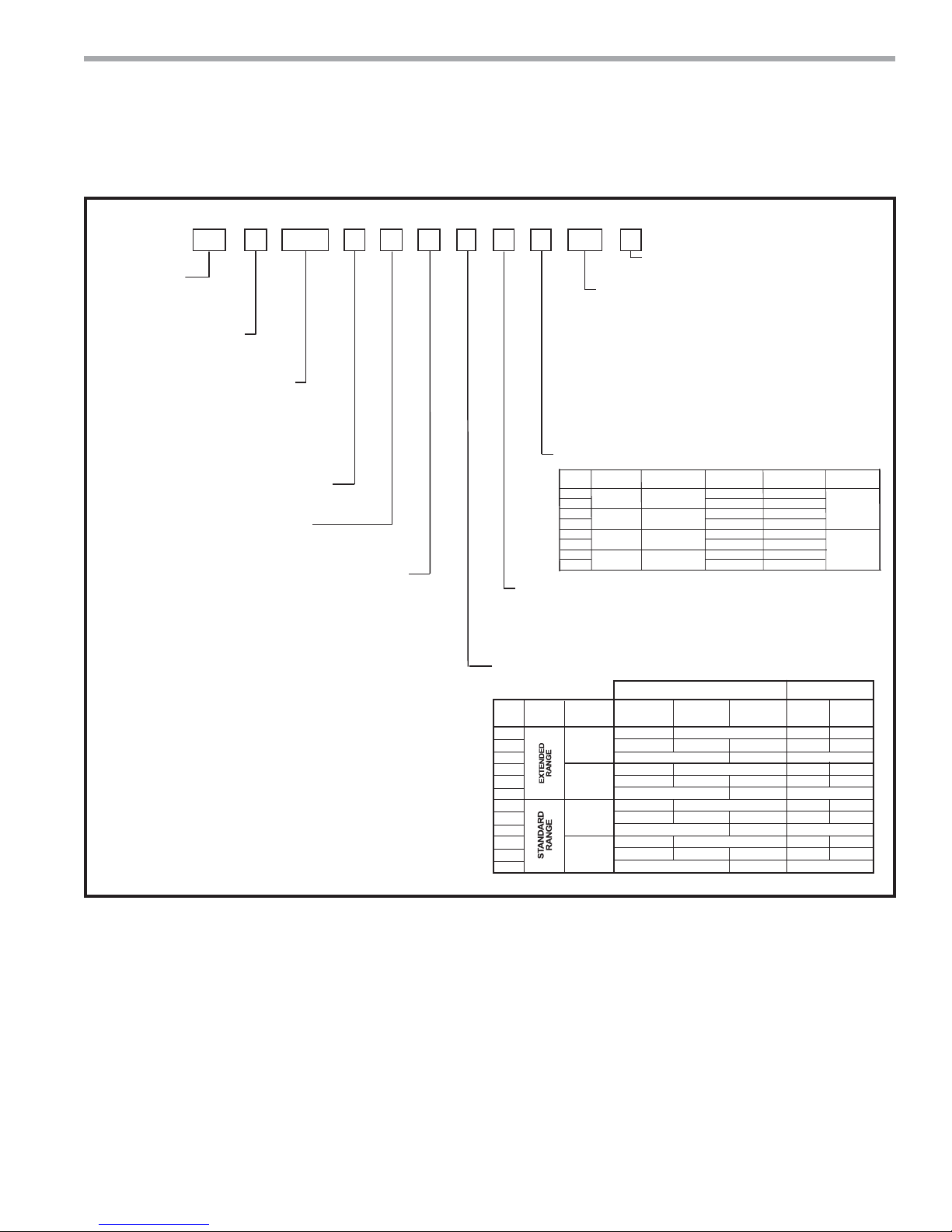
MODEL TYPE
TC = TRANQUILITY
COMMERCIAL HFC-410A
®
COMPACT
CONFIGURATION
H = HORIZONTAL
V = VERTICAL
TCV
ONLY
®
Compact Belt Drive (TCH/V) Series
1 2 3 4 5 6 7
Tranquility
9 10 11 12 13 14 15
8
TC H A0 9 6 CH 3 A A L S S
AIR FLOW OPTIONS
LB = LEFT RETURN/BACK DISCHARGE
LS = LEFT RETURN/STRAIGHT DISCHARGE
RB = RIGHT RETURN/BACK DISCHARGE
RS = RIGHT RETURN/STRAIGHT DISCHARGE
VB = LEFT RETURN S.S. DRAIN PAN/BACK DISCHARGE
VS = LEFT RETURN S.S. DRAIN PAN/STRAIGHT DISCHARGE
WB = RIGHT RETURN S.S. DRAIN PAN/BACK DISCHARGE
¢
WS = RIGHT RETURN S.S. DRAIN PAN/STRAIGHT DISCHARGE
BF = BACK RETURN/FRONT DISCHARGE
BT= BACK RETURN/TOP DISCHARGE
FB = FRONT RETURN/BACK DISCHARGE
FT = FRONT RETURN/TOP DISCHARGE
YF = BACK RETURN S.S. DRAIN PAN/FRONT DISCHARGE
YT = BACK RETURN S.S. DRAIN PAN/TOP DISCHARGE
ZB = FRONT RETURN S.S. DRAIN PAN/BACK DISCHARGE
¢
ZT = FRONT RETURN S.S. DRAIN PAN/T OP DISCHARGE
COPPER
WATER COIL
YES
NO
YES
NO
NO
YES
NO
YES
UNIT SIZE
072
096
120
160
192
240
¢
300
REVISION LEVEL
A = CURRENT REVISION
VOLTAGE
F = 460/60/3
H = 208/230/60/3 (FACTORY WIRED 208)
N = 575/60/3
CONTROLS
C = CXM
¢
D = DXM
L = CXM w/LON
M = DXM w/LON
N = CXM w/MPC
P = DXM w/MPC
ETL Approved
USA & Canada
TCH
ONLY
TCV
ONLY
HEAT EXCHANGER OPTIONS
OPTION
A
C
J
N
1
2
3
4
BLOWER DRIVE PACKAGE
A = ST ANDARD RPM & ST ANDARD MOTOR
B = LOW RPM & STANDARD MOTOR
C = HIGH RPM & STANDARD MOTOR
D = STANDARD RPM & LARGE MOTOR
E = HIGH RPM & LARGE MOTOR
CABINET INSULATION / FILTER RAILS/FRAMES
OPTION RANGE
1
A
B
2
C
D
3
E
F
4
G
H
ULTRA QUIET
S = STANDARD
A = DUAL POINT POWER
CUPRO-NICKEL
WATER COIL
NO
YES
NO
YES
TCV TCH
1” FILTER
FRAMES
YES
NO
YES
NO
YES
NO
YES
NO
NO
NO
NO
NO
2” FILTER
FRAMES
YES
YES
YES
YES
Rev.: July 25, 2017
Model Nomenclature
N/A
N/A
N/A
N/A
YES
NO
YES
NO
1” FILTER
RAIL
YES
NO
YES
NO
YES
NO
YES
NO
WATER SIDE
ECONOMIZER
NO
YES
2” FILTER
RAIL
NO
YES
NO
NO
YES
NO
NO
YES
NO
NO
YES
NO
COATED
AIR COIL
YES
NO
YES
NO
YES
NO
YES
NO
NO
NO
NO
NO
4” FILTER
FRAMES
NO
YES
NO
YES
NO
YES
NO
YES
COATED
ECON COIL
climatemaster.com
3
CLIMATEMASTER WATER-SOURCE HEAT PUMPS
S
P
on
Tranquility
Rev.: July 25, 2017
®
Compact Belt Drive (TCH/V) Series
General Information
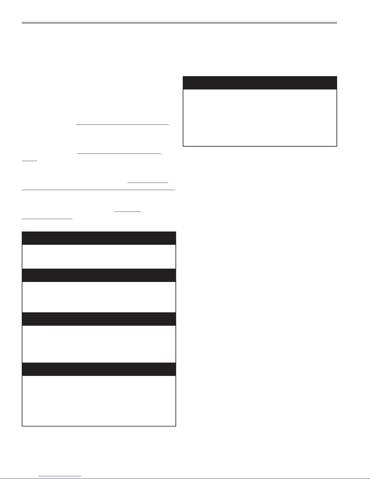
Safety
Warnings, cautions and notices appear throughout this
manual. Read these items carefully before attempting any
installation, service or troubleshooting of the equipment.
DANGER: Indicates an immediate hazardous situation,
which if not avoided will result in death or serious injury.
DANGER labels on unit access panels must be observed.
WARNING: Indicates a potentially hazardous situation,
which if not avoided could result in death or serious
injury.
CAUTION: Indicates a potentially hazardous situation or
an unsafe practice, which if not avoided could result in
minor or moderate injury or product or property damage.
NOTICE: Notifi cation of installation, operation or
maintenance information, which is important, but which is
not hazard-related.
WARNING!
WARNING! The EarthPure® Application and Service Manual
should be read and understood before attempting to service
refrigerant circuits with HFC-410A.
WARNING!
WARNING! To avoid the release of refrigerant into the
atmosphere, the refrigerant circuit of this unit must be
serviced only by technicians who meet local, state, and
federal profi ciency requirements.
CAUTION!
CAUTION! To avoid equipment damage, DO NOT use
these units as a source of heating or cooling during the
construction process. The mechanical components and
fi lters will quickly become clogged with construction dirt and
debris, which may cause system damage.
WARNING!
WARNING! The installation of water-source heat pumps and
all associated components, parts, and accessories which
make up the installation shall be in accordance with the
regulations of ALL authorities having jurisdiction and MUST
conform to all applicable codes. It is the responsibility of
the installing contractor to determine and comply with ALL
applicable codes and regulations.
torage
re-Installati
WARNING!
WARNING! All refrigerant discharged from this unit must
be recovered WITHOUT EXCEPTION. Technicians must
follow industry accepted guidelines and all local, state, and
federal statutes for the recovery and disposal of refrigerants.
If a compressor is removed from this unit, refrigerant circuit
oil will remain in the compressor. To avoid leakage of
compressor oil, refrigerant lines of the compressor must be
sealed after it is removed.
Inspection the shipment against the bill of lading. Make sure all units
have been received. Inspect the packaging of each unit, and
inspect each unit for damage. Ensure that the carrier makes
proper notation of any shortages or damage on all copies of
the freight bill and completes a common carrier inspection
report. Concealed damage not discovered during unloading
must be reported to the carrier within 15 days of receipt of
shipment. If not fi led within 15 days, the freight company can
deny the claim without recourse. Note: It is the responsibility
of the purchaser to fi le all necessary claims with the carrier.
Notify your equipment supplier of all damage within fi fteen
(15) days of shipment.
Storage - Equipment should be stored in its original
packaging in a clean, dry area. Store units in an upright
position at all times.
Unit Protection -
the original packaging or an equivalent protective covering.
Cap the open ends of pipes stored on the job site. In areas
where painting, plastering, and/or spraying has not been
completed, all due precautions must be taken to avoid
physical damage to the units and contamination by foreign
material. Physical damage and contamination may prevent
proper start-up and may result in costly equipment clean-up.
Examine all pipes, fi ttings, and valves before installing
any of the system components. Remove any dirt or debris
found in or on these components.
Pre-Installation - Installation, Operation, and Maintenance
instructions are provided with each unit. Horizontal
equipment is designed for installation above false ceiling
or in a ceiling plenum. Other unit confi gurations are
typically installed in a mechanical room. The installation
site chosen should include adequate service clearance
around the unit. Before unit start-up, read all manuals
and become familiar with the unit and its operation.
Thoroughly check the system before operation.
Upon receipt of the equipment, carefully check
Cover units on the job site with either
4
ClimateMaster Water-Source Heat Pumps

THE SMART SOLUTION FOR ENERGY EFFICIENCY
Tranquility
Prepare units for installation as follows:
1. Compare the electrical data on the unit nameplate
with ordering and shipping information to verify that
the correct unit has been shipped.
2. Keep the cabinet covered with the original packaging
until installation is complete and all plastering,
painting, etc. is fi nished.
3. Verify refrigerant tubing is free of kinks or dents and
that it does not touch other unit components.
4. Inspect all electrical connections. Connections must
be clean and tight at the terminals.
5.
Some airfl ow patterns and some control box
locations are fi eld convertible. Locate the conversion
section of this IOM.
®
Compact Belt Drive (TCH/V) Series
Rev.: July 25, 2017
CAUTION!
CAUTION! All three phase scroll compressors must have
direction of rotation verifi ed at start-up. Verifi cation is
achieved by checking compressor Amp draw. Amp draw
will be substantially lower compared to nameplate values.
Additionally, reverse rotation results in an elevated sound
level compared to correct rotation. Reverse rotation will result
in compressor internal overload trip within several minutes.
Verify compressor type before proceeding.
CAUTION!
CAUTION! DO NOT store or install units in corrosive
environments or in locations subject to temperature or
humidity extremes (e.g., attics, garages, rooftops, etc.).
Corrosive conditions and high temperature or humidity can
signifi cantly reduce performance, reliability, and service life.
Always move and store units in an upright position. Tilting
units on their sides may cause equipment damage.
CAUTION!
CAUTION! CUT HAZARD - Failure to follow this caution may
result in personal injury. Sheet metal parts may have sharp
edges or burrs. Use care and wear appropriate protective
clothing, safety glasses and gloves when handling parts and
servicing heat pumps.
climatemaster.com
5
CLIMATEMASTER WATER-SOURCE HEAT PUMPS
Tranquility
Rev.: July 25, 2017
®
Compact Belt Drive (TCH/V) Series
TCH Physical Data
Model 072 096 120
Compressor Quantity Scroll
Number of Circuits (Compressors) 2
Factory Charge HFC-410a (oz) [kg] per
circuit
Blower Motor Quantity 1
Standard Motor (hp) [kW] 1 [0.75] 2 [1.49] 3 [2.24]
Large Motor (hp) [kW] 2 [1.49] 3 [2.24] 5 [3.73]
No. of Blowers 1
Blower Wheel Size D x W (in) [cm] 12 x 12 [30.48 x 30.48]
Water Connection Size
FPT (in) [mm] 1-1/4" [31.8] 1-1/2" [38.1]
Volume (US Gallons) [liters] 1.62 [6.13] 1.81 [6.85] 2.40 [9.08]
Condensate Connection Size
FPT (in) [mm] 3/4" [19.1]
Air Coil Dimensions H x W (in) [cm] 20 x 54 [50.8 x 137.2] 20 x 64 [50.8 x 162.6]
Air Coil Total Face Area (ft2) [m2]
Miscellaneous Data
Filter Standard - 1" [25.4mm] Throwaway
(qty) (in) [cm]
Weight - Operating (lbs) [kg] 586 [265.8] 644 [292.1] 698 [316.6]
Weight - Packaged (lbs) [kg] 626 [283.9] 684 [310.3] 738 [334.8]
All units have grommet compressor mountings, and 1/2" & 1-3/4" electrical knockouts.
60 [1.70] 76 [2.15] 80 [2.27]
Blower Motor
Blower
Coax Volume
Air Coil Data
7.5 [0.70] 8.9 [0.83]
(QTY.3) 16 x 20 [40.6 x 50.8]
(QTY.1) 20 x 20 [50.8 x 50.8]
TCH072-120 Corner Weights
Weight - Operating (lbs) [kg] 586 [265.8] 644 [292.1] 698 [316.6]
Weight - Packaged (lbs) [kg] 626 [283.9] 684 [310.3] 738 [334.8]
Weight - Corner - Control box/Compressor side (lbs) [kg] 235 [106.6] 254 [115.2] 271 [122.9]
Weight - Corner - Compressor side (lbs) [kg] 101 [45.8] 120 [54.4] 137 [62.1]
Weight - Corner - Blower side (lbs) [kg] 180 [81.6] 190 [86.2] 200 [90.7]
Weight - Corner - Air Coil side (lbs) [kg] 70 [31.8] 80 [36.3] 90 [40.8]
Unit with WSE Option
TCH072 TCH096 TCH120
TCH Series 072 096 120
Water Coil Dimensions (in) [cm]
Internal Water Coil Volume (Gal) [L]
Weight - Operating (lbs.) [Kg]
Weight - Packaged (lbs.) [Kg]
20 x 54 [50.8 x 137.2] 20 x 60 [50.8 x 152.4]
5.6 [21.6] 6.2 [23.5] 6.8 [25.7]
838 [380] 921 [418] 998 [453]
900 [408] 978 [444] 1058 [480]
6
ClimateMaster Water-Source Heat Pumps

THE SMART SOLUTION FOR ENERGY EFFICIENCY
HANGER BRACKET DIMENSIONS
87”
[221cm]
1.0”
[2.54cm]
PLAN VIEW
TOP
4.3”
[10.8cm]
34.1”
[86.6cm]
FRONT
CONTROL BOX
U
T
S
V
1.3”
[3.3cm]
condensate
LEFT RETURN LEFT VIEW-
AIR COIL SIDE
LEFT RETURN END DISCHARGE
CBP
EAP
BSP
CAP
CAP
FRONT
E
D
F
G
CAP
CBP
CAP
EAP
BSP
FRONT
FRONT
CONTROL BOX
PLAN VIEW
TOP
V
S
U
RIGHT RETURN RIGHT VIEW-
AIR COIL SIDE
RIGHT RETURN END DISCHARGE
1.3”
[3.3cm]
condensate drain
3
LEFT RETURN STRAIGHT DISCHARGE
CAP
CAP
FRONT
BSP
A
EAP
CBP
B
C
O
P
Q
R
K
M
F
G
E
D
BSP
RIGHT RETURN STRAIGHT DISCHARGE
1
EAP
2 CAP
CAP
2
FRONT
CBP
1
5
4
LEGEND
CAP=Compressor Access Panel
CBP=Control Box Panel
BSP=Blower Service Panel
EAP=Expansion Valve Access panel
1=Water Outlet 1-1/4” FPT (072-096) 1-1/2” FPT (120)
2=Water Inlet 1-1/4” FPT (072-096) 1-1/2” FPT (120)
3=Condensate 3/4” FPT
4=High Voltage 1-1/8” [2.9cm] KO
5=Low Voltage 7/8” [2.2cm] KO
SERVICE ACCESS
3’ (91 cm.)
Note 5, 6
Note 6
Note 6
Note 6
ALL CONFIGURATIONS REQUIRE SERVICE ACCESS AREA
DESCRIBED IN NOTES 5 AND 6.
NOTES:
-
All dimensions in table are inches (cm).
6HUYLFHDccess is required for all removable panels and installer should take care to comply with all building codes and
allowadequate clearance for future field service.
Water inlet and water outlet connections are available on either side (left or right) of the unit. Qty (2x) MPT Plugs are
shipped loose in a plastic bag tied to the water leg in front of the unit. Installer must plug water inlet/outlet side not being
connected to.
&RQGHQVDWHGUDLQLV)37DQGLVORFDWHGRQFDELQHWHQGRSSRVLWHWKHFRPSUHVVRU
Electrical access is available on either side (left or right) of the front.
Electric box is on right side. It can be field converted to left side. Conversion should only be attempted by qualified
service technician. If electric box relocated to opposite side, and water connected to opposite side, then this access is
not required.
Units require 3’ (9.1 cm) clearance for water connections, CAP, C%P, EAP and BSP service access.
Overall cabinet width dimensions does not include filter rail and duct flange.
8QLWVDUHVKLSSHGZLWKDLUILOWHUUDLOVWKDWDUHQRWVXLWDEOHIRUVXSSRUWLQJUHWXUQDLUGXFWZRUN$QDLUILOWHUIUDPHZLWKGXFW
PRXQWLQJFROODULVDYDLODEOHDVDQDFFHVVRU\
Tranquility
®
Compact Belt Drive (TCH/V) Series
Rev.: July 25, 2017
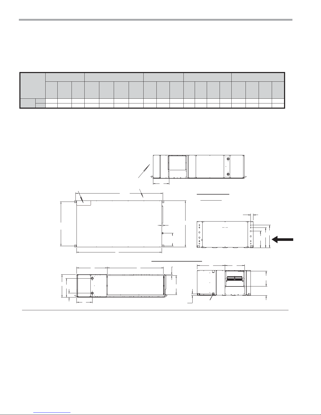
TCH072-120 Dimensional Data
TCH072-120 Dimensional Data
Overall Cabinet Discharge Connections Duct Flange Water Connections Electrical Knockouts Return Air Connections Using Return Air Opening
A
Model
072-120
DepthBWidthCHeight
36.3 84.9 21.6 14.0 17.0 13.5 7.8 15.0 8.3 4.0 2.0 18.8 16.8 13.8 65.0 18.0 1.0 18.9
in.
92.2 215.6 54.9 35.6 43.2 34.3 19.8 38.1 21.1 10.2 5.1 47.8 42.7 35.1 165.1 45.7 2.5 48.0
cm.
DE
Supply
Depth
F
Supply
Width
G
Supply
Height
climatemaster.com
KL
1
Water
Outlet
M
OPQ R S
2
Water
Inlet
Return
Depth
T
Return
Height
UV
7
CLIMATEMASTER WATER-SOURCE HEAT PUMPS
Tranquility
®
Compact Belt Drive (TCH/V) Series
Rev.: July 25, 2017
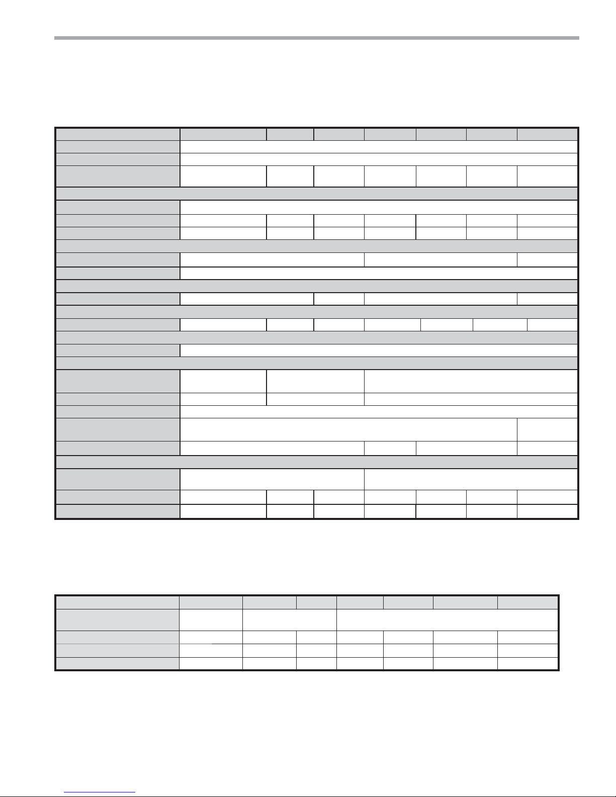
TCH072-120 w/WSE Dimensional Data
TCH 072-120 with WaterSide Economizer
Overall Cabinet
Model
072-120
A
WidthBDepthCHeight
46.3 84.9 21.6 23.9 17.0 13.5 7.8 15.0 18.3 4.0 2.0 18.8 16.8 13.8 54.0 18.4 1.0 29.4
in.
117.6 215.6 54.9 60.9 43.2 34.3 19.8 38.1 46.4 10.2 5.1 47.8 42.7 35.1 137.2 45.7 2.5 74.7
cm.
Legend
BSP = Blower Service Panel
CAP = Compressor Access Panel
CBP = Control Box Panel
MSP = Motor Service Panel
ACP = Aquastat Controller Panel
EAP = Expansion Valve Access Panel
WSE = Waterside Economizer
Discharge Connections
Duct Flange
DE
Supply
Depth
F
Supply
Width
G
Supply
Height
Water Connections Electrical Knockouts
KL
Water
Outlet
M
OP Q R S
1
2
Water
Inlet
EAP
Notes 6, 9
Return Air Connections
Using Return Air Opening
T
UV
Return
Return
Depth
Height
87.00
[221 CM]
MSP BSP
Notes 6,7
CBP
Notes 5, 6
F
R
44.16
[112.18 CM]
C
Notes:
1. Service access is required for all removable panels and installer
should take care to comply with all building codes allowing
adequate clearance for future field service.
2. Units are shipped with air filter rails that are not suitable for
supporting return air ductwork. An air filter frame with duct
mounting collar is available as an accessory.
3. Discharge flange and hanger brackets are factory installed.
4. Condensate drain is 3/4” FPT and is located on cabinet end
opposite the compressor.
5. Unit control box is on side opposite return air (not convertible)
6. Units require 3 feet (91cm) clearance for water connections,
CAP, CBP, EAP, MSP, ACP and BSP service panels.
O
N
T
B
V
L
M
K
Right Side View
Top View
S
15.00 (38.1)
Straight Discharge
A
1.00
[2.54 CM]
12.75
[32.39 CM]
Right Return Back Discharge
U
T
1.3 (3.3cm)
7. Blower service access is through back panel on straight discharge
units or through panel opposite air coil on back discharge units.
8. Factory supplied controller (aquastat) is inside unit completely wired.
To field adjust temperature setting, remove ACP panel and push button.
9. Expansion valve access panel is opposite return air side.
10. WSE coil air bleed access is through CAP.
Left Side View
Right Return
Front View
WSE
3/4” Drain
FPT
CAP, ACP
Notes 6, 8, 10
ED
Back View
O
Return
P
Air
Q
R
Flow
F
G
8
ClimateMaster Water-Source Heat Pumps
THE SMART SOLUTION FOR ENERGY EFFICIENCY
Tranquility
®
Compact Belt Drive (TCH/V) Series
Rev.: July 25, 2017
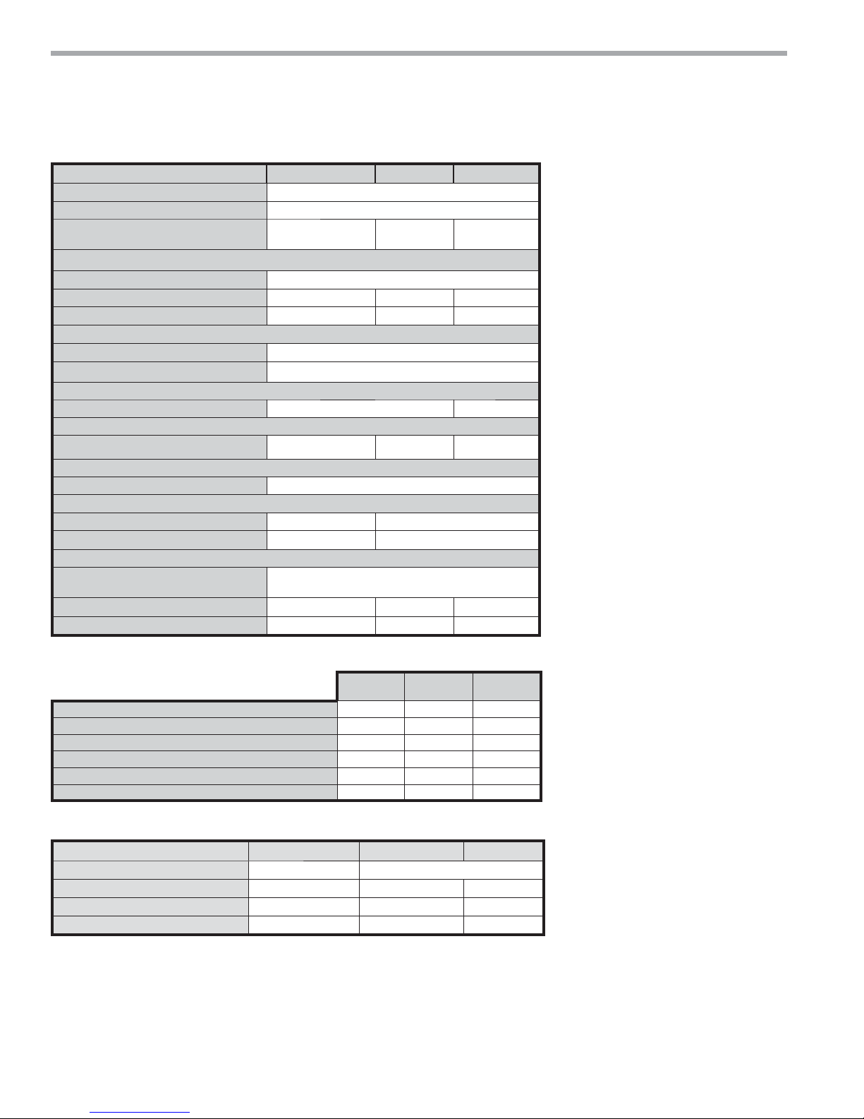
TCV Physical Data
Model
Compressor Scroll
Number of Circuits (Compressors) 2
Factory Charge HFC-410a - (oz)
[kg] per circuit
Blower Motor
Blower Motor Quantity 1
Standard Motor (hp) [kw] 1 [.75] 2 [1.49] 3 [2.23] 3 [2.24] 3 [2.24] 5 [3.73] 7.5 [5.60]
Optional Large Motor (hp) [kw] 2 [1.49] 3 [2.24] 5 [3.73] 5 [3.73] 5 [3.73] 7.5 [5.59] 10 [7.46]
Blower
No. of Blowers 1 2 3
Blower Wheel Size D x W (in) [cm] 12 x 12 [30.48 x 30.48]
Water Connection Size
FPT (in) [mm] 1-1/4" [31.8] 1-1/2" [38.1] 2" [50.8] 2-1/2" [63.5]
Coax Volume
Volume (US Gallons) [liters] 1.62 [6.13] 1.81 [6.85] 2.40 [9.08] 3.62 [13.70] 4.83 [18.28] 4.90 [18.55] 7.39 [27.98]
Condensate Connection Size
FPT (in) [mm] 1" [25.4]
Air Coil Data
072 096 120 160 192 240 300
60 [1.70] 76 [2.15] 80 [2.27] 112 [3.18] 136 [3.86] 196 [5.56] 224 [6.35]
Air Coil Dimensions H x W (in) [cm] 32 x 34 [81.28 x 86.36] 36 x 36 [91.44 x 91.44] 36 x 76 [91.44 x 193.04]
Air Coil Total Face Area (ft
Air Coil Tube Size (in) [cm] 3/8" [0.953]
Air Coil Fin Spacing (fpi)
[fi ns per cm]
Air Coil Number of Rows 3 2 3 4
2
) [m2] 7.6 [0.71] 9.0 [0.84] 19 [1.77]
14 [5.5] 12 [4.72]
Miscellaneous Data
Filter Standard - 1" [25.4mm]
Throwaway (qty) (in) [cm]
Weight - Operating (lbs) [kg] 586 [265.8] 644 [292.1] 698 [316.6] 1069 [484.9] 1164 [528.0] 1184 [537.1] 1297 [588.3]
Weight - Packaged (lbs) [kg] 626 [283.9] 684 [310.3] 738 [334.8] 1149 [521.2] 1244 [564.3] 1264 [573.3] 1377 [624.6]
Unit with WSE Option
(QTY.4) 20 x 20 [50.8 x 50.8]
(QTY.4) 20 x 25 [50.80 x 63.5]
(QTY.2) 20 x 30 [50.80 x 76.2]
TCV Series 072 096 120 160 192 240 300
Water Coil Dimensions (in x cm)
Internal Water Coil Volume (Gal) [L]
Weight - Operating (lbs.) [Kg]
Weight - Packaged (lbs.) [Kg]
32 x 34 [81.28 x
86.36]
5.9 [22.3] 6.6 [25] 7.2 [27.3] 13.3 [50.3] 14.5 [54.9] 23.9 [90.5] 26.4 [99.9]
762 [346] 837 [378] 907 [411] 1529 [694] 1665 [755] 1693 [768] 1855 [841]
814 [369] 889 [403] 962 [436] 1643 [745] 1779 [807] 1808 [820] 1974 [895]
35 x 36 [88.9 x 91.4] 35 x 76 [88.9 x 193]
climatemaster.com
9
CLIMATEMASTER WATER-SOURCE HEAT PUMPS
AIR OUT
AIR OUT
AIR OUT
NRP
BLOWER
ROTATION
NRP
NRP
NRP
RETURN AIR
RETURN AIR
BLOWER TO AIR COIL
RELATIONSHIP FOR
REAR OR FRONT
DISCHARGE 072-120
RETURN AIR
UPA
BSP
BSP
2
2
2
3
4
4
5
CSP+CAP+MSP
1
1
1
CSP+CAP+MSP
CSP+CAP+MSP
4
4
5
7.6
F
L
K
M
SIDE
SERVICE ACCESS
(See Note 8)
SERVICE ACCESS
·&0
FRONT AND BACK
1.7
E
F
D
F
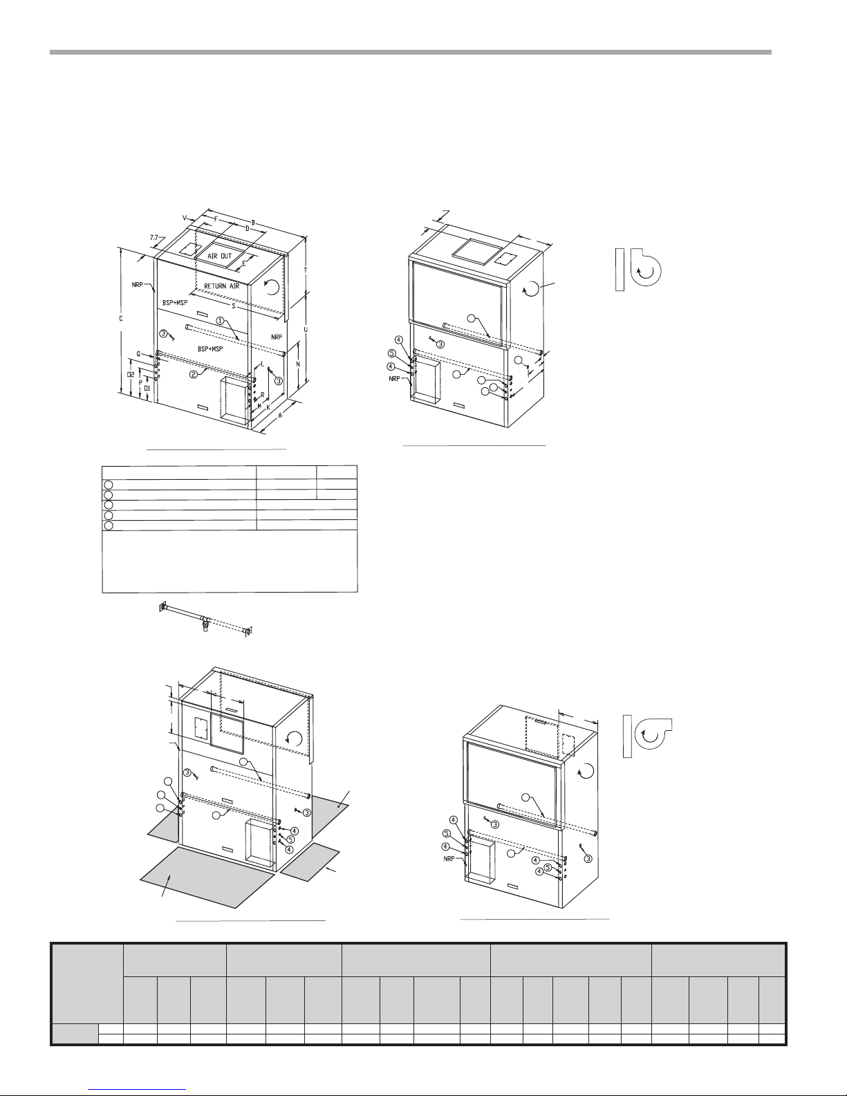
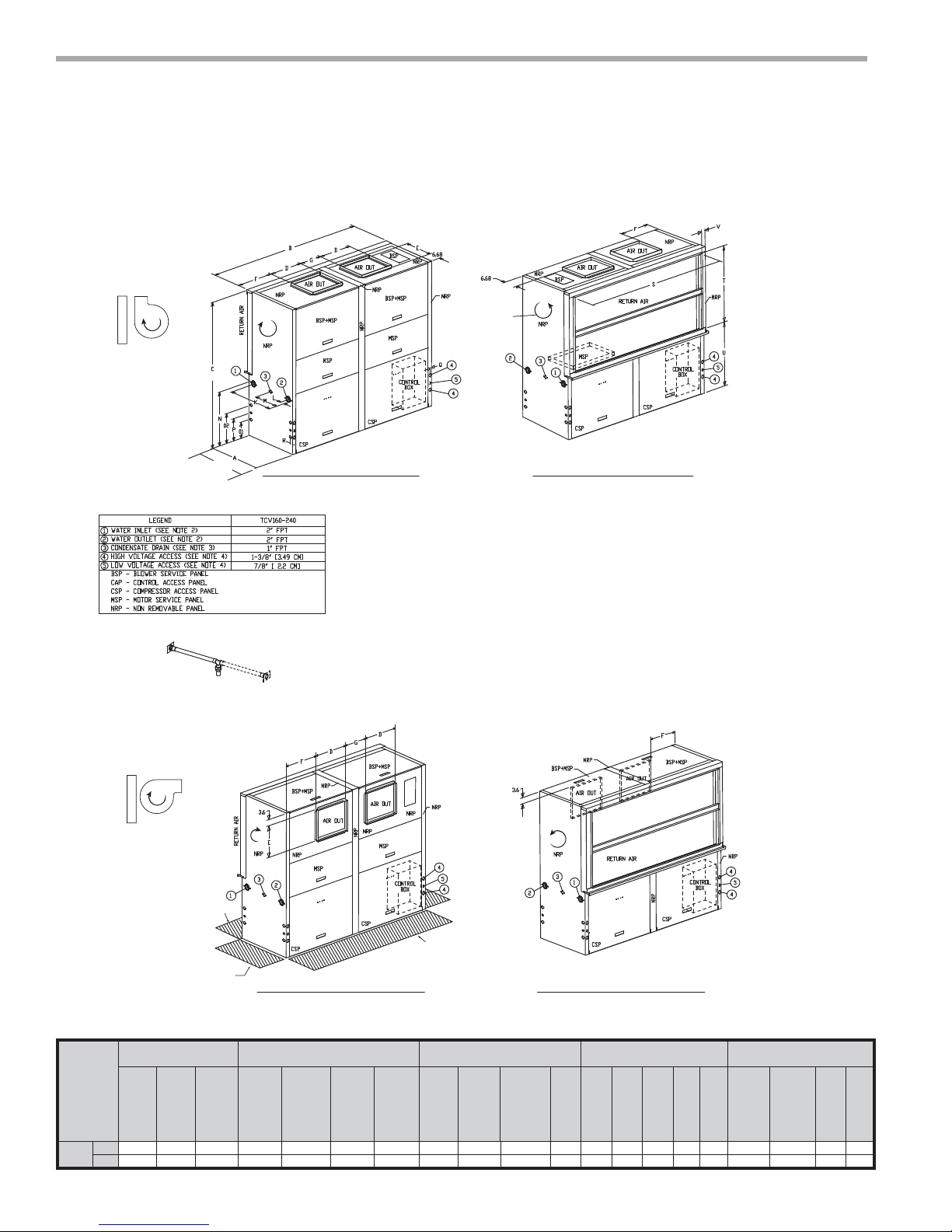
LEGEND
7&9
TCV120
Water Inlet (See Note 2)
Water Outlet (See Note 2)
Condensate Drain (See Note 3)
High Voltage Access (See Note 4)
Low Voltage Access (See Note 4)
1-1/4” FPT
1-1/4” FPT
1-1/2” FPT
1-1/2” FPT
1” FPT
µ>&0@
µ>&0@
BSP - Blower Service Panel
CAP - Control Access Panel
CSP - Compressor Access Panel
MSP - Motor Service Panel
NRP - Non Removable Panel
UPA - Upper Pulley Access
1
2
3
4
5
FRONT RETURN REAR DISCHARGE (FR/RD)
REAR RETURN FRONT DISCHARGE (RR/FD)
REAR RETURN TOP DISCHARGE (RR/TD)
FRONT RETURN TOP DISCHARGE (FR/TD)
NOTES:
All dimensions in table are inches (cm)
1. While access to all removable panels may not be required, installer should take care to
comply with all building codes and allow adequate clearance for future field service.
2. Water inlet and water outlet connections are factory shipped on the left side. Union
allows field conversion to right side.
3. Condensate drain is available on either side (left or right) of unit. Drain hose and drain
connection will be tied inside the unit. Installer will untie the drain hose, form trap, and
FRQQHFWWRWKHFRQGHQVDWHGUDLQKROHRILQVWDOOHU·VFKRLFH
4. Electrical access is available on either side (left or right) of unit and is also available in
the front on the left or right side of the unit.
5. Overall width - Add 3.12” (8cm) for 1“ (2.5cm) or 2” (5cm) Filter Frame; or 5.12” (13cm)
for 4” (10.2cm) and for front or rear supply add additional 1.06” (2.7cm) for supply
duct collar.
6. Overall cabinet height dimension does not include duct flange for top discharge
configuration.
8QLWVUHTXLUHIHHWFPFOHDUDQFH&$3&63063DQG%63VHUYLFHDFFHVV
6LGHVHUYLFHDFFHVVPXVWEHIHHWFPRQDQ\VLGHWKDWFRQQHFWLRQVDUHPDGH
)LOWHUUHPRYDOLVIURPULJKWRUOHIWVLGHRIILOWHUIUDPHDOORZIHHWFPDFFHVV
for servicing.
BSP
UPA
ALL CONFIGURATIONS REQUIRE SERVICE ACCESS AREA
DESCRIBED IN NOTES 7, 8, and 9
(See Notes 1 and 7)
(See Notes 1 and 7)
Note 2
ALL CONFIGURATIONS
BLOWER TO AIR COIL
RELATIONSHIP FOR
TOP DISCHARGE
072-120
BSP+MSP
CSP
(See Note 6)
Control
Box
Control
Box
Control
Box
Control
Box
Tranquility
®
Compact Belt Drive (TCH/V) Series
Rev.: July 25, 2017
TCV072-120 Dimensional Data
Model
072-120
10
Discharge Connection
Duct Flange
Supply
Width
Depth
Depth Width Height
in. 29.0 41.0 69.8 17.5 14.8 11.9 22.0 7.3 14.5 21.3 8.0 15.0 11.3 1.0 1.5 36.3 29.4 30.6 2.7
cm. 73.7 104.1 177.2 44.5 37.5 30.2 55.9 18.4 36.8 54.0 20.3 38.1 28.6 2.5 3.8 96.2 74.7 77.8 6.9
Overall Cabinet
A B C D E F K L M N O 1 O 2 P Q R S T U V
Supply
Conden-
sate
3
Water Connections Electric Knockouts
1
Water
Inlet
ClimateMaster Water-Source Heat Pumps
2
Water
Outlet
Return Air Connections Using
Return Air Opening
Return
Return
Depth
Height
THE SMART SOLUTION FOR ENERGY EFFICIENCY
TCV 072-120 with WaterSide Economizer
Discharge Connection
Supply
Width
B
BSP
Note 5
Duct Flange
Supply
Depth
Model
072-120
Overall Cabinet
A B C D E F K L M N O 1 O 2 P Q R S T U V
Depth Width Height
in. 39.5 41.0 69.8 17.5 14.8 11.9 22.0 7.3 14.5 21.3 8.0 15.0 11.3 1.0 1.5 36.3 29.4 30.6 2.7
cm. 100.3 104.1 177.2 44.5 37.5 30.2 55.9 18.4 36.8 54.0 20.3 38.1 28.6 2.5 3.8 96.2 74.7 77.8 6.9
Top View
Rear Return Front Discharge
Tranquility
Water Connections Electric Knockouts
1
Water
Inlet
2
Water
Outlet
Conden-
®
Compact Belt Drive (TCH/V) Series
3
sate
Legend
BSP = Blower Service Panel
CSP = Compressor Service Panel
CAP = Control Access Panel
MSP = Motor Service Panel
UPA = Upper Pulley Access
ACP = Aquastat Controller Panel
WSE = Waterside Economizer
Rev.: July 25, 2017
TCV072-120 Dimensional Data
Return Air Connections Using
Return Air Opening
Return
Return
Depth
Height
UPA
Note 5
BSP
Note 5
Top View
Rear Return Top Discharge
7.72
F
3.68
D
UPA
Note 5
C
WSE Coil Air
Bleed Access
Note 2
E
Alternate
MSP
CAP
O2
CSP, ACP
P
O1
Front View
Q
Note 2
N
R
Rear Return Front Discharge
Notes:
1. While clear access to all removable panels may not be
required, installer should take care to comply with all building
codes and allow adequate clearance for future field service.
2. Units require 3 feet (91 cm) clearance for water connections,
WSE coil air bleed, CAP, CSP, BSP, ACP, UPA, and MSP.
A
BSP
Note 5
WSE
MSP
Note 2
L
M
K
3. Factory supplied controller (aquastat) is inside unit completely
wired. To field adjust temperature setting remove ACP panel and push button.
4. Internally trapped, externally vented.
5. For top discharge units, UPA in on top and BSP is on front. For front discharge
units, UPA is on front and BSP in on top. (allow 3 feet above unit for service).
Right
Side
View
Return
Air
Flow
Rear Return Front Discharge
S
Back View
V
T
U
climatemaster.com
11
CLIMATEMASTER WATER-SOURCE HEAT PUMPS
Tranquility
®
Compact Belt Drive (TCH/V) Series
Rev.: July 25, 2017
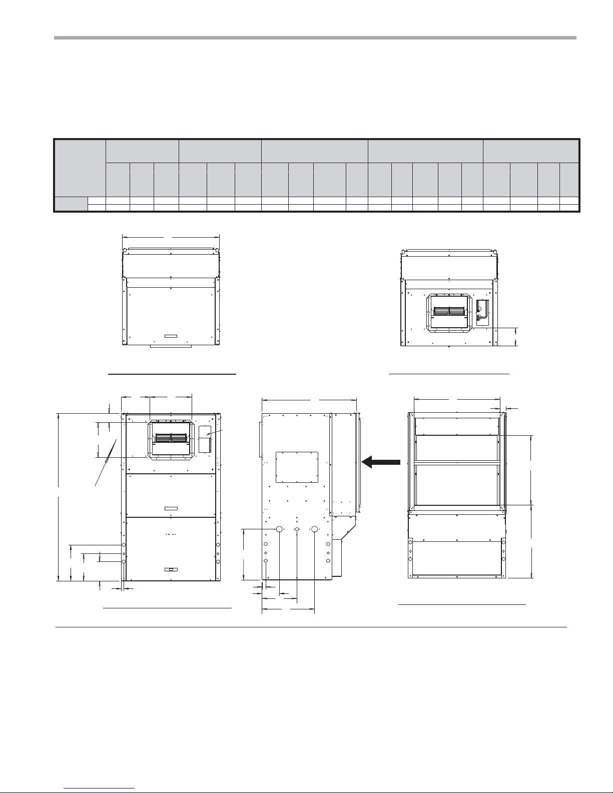
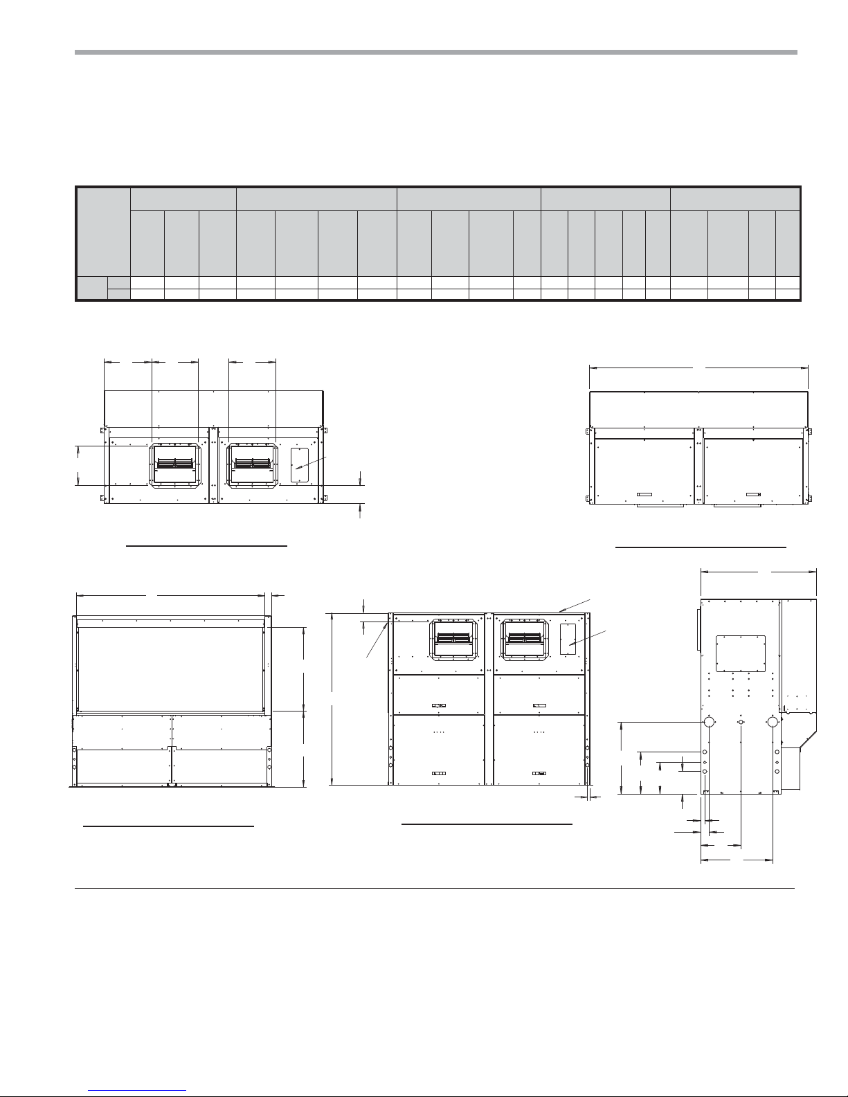
TCV160-240 Dimensional Data
ALL CONFIGURATIONS REQUIRE SERVICE ACCESS AREA
BLOWER TO AIR COIL
RELATIONSHIP FOR
TOP DISCHARGE
160-240
(See Note 6)
(See Note 5)
Note 2
REAR RETURN TOP DISCHARGE (RR/TD)
ALL CONFIGURATIONS
DESCRIBED IN NOTES 7, 8, and 9
BLOWER
ROTATION
FRONT RETURN TOP DISCHARGE (FR/TD)
NOTES:
All dimensions in table are inches (cm)
1. While access to all removable panels may not be required, installer should take care
to comply with all building codes and allow adequate clearance for future field service.
2. Water inlet and water outlet connections are factory shipped on the left side. Union
allows field conversion to right side.
3. Condensate drain is available on either side (left or right) of unit. Drain hose and drain
connection will be tied inside the unit. Installer will untie the drain hose, form trap, and
FRQQHFWWRWKHFRQGHQVDWHGUDLQKROHRILQVWDOOHU·VFKRLFH
4. Electrical access is available on either side (left or right) of unit and is also available in
the front on the left or right side of the unit.
5. Overall width - Add 3.12” (8cm) for 1“ (2.5cm) or 2” (5cm) Filter Frame; or 5.12” (13cm)
for 4” (10.2cm) and for front or rear supply add additional 1.06” (2.7cm) for supply
duct collar.
6. Overall cabinet height dimension does not include duct flange for top discharge
configuration.
8QLWVUHTXLUHIHHWFPFOHDUDQFH&$3&63063DQG%63VHUYLFHDFFHVV
6LGHVHUYLFHDFFHVVPXVWEHIHHWFPRQDQ\VLGHWKDWFRQQHFWLRQVDUHPDGH
)LOWHUUHPRYDOLVIURPULJKWRUOHIWVLGHRIILOWHUIUDPHDOORZIHHWFPDFFHVV
for servicing.
BLOWER TO AIR COIL
RELATIONSHIP FOR
REAR OR FRONT
DISCHARGE 160-240
See Notes
1 and 7
SIDE SERVICE
ACCESS
(See Note 8)
Overall Cabinet
A
REAR RETURN FRONT DISCHARGE (RR/FD)
Discharge Connection Duct
Flange
D
E
Model
DepthB WidthC Height
in. 29.0 82.0 69.8 17.5 14.8 17.9 11.5 26.1 3.1 14.5
160-
240
cm. 73.7 208.3 177.2 44.5 37.5 45.4 29.3 66.3 7.9 36.8
12
Supply
Width
Supply
Depth
SERVICE ACCESS
·&0
FRONT AND BACK
(See Notes 1 and 7)
FRONT RETURN REAR DISCHARGE (FR/RD)
Water Connections Electrical Knockouts
F
G
K
Supply
Width
Supply
Depth
Water
Inlet
L
Water
Outlet
Conden-
sate
N
M
25.8
65.5
ClimateMaster Water-Source Heat Pumps
Return Air Connections
Using Return Air Opening
O 1 O 2 P Q R
S
Return
Depth
Return
Height
U V
T
8.0 15.0 11.3 1.0 1.5 77.0 35.8 31.7 2.6
20.3 38.1 28.6 2.5 3.8 195.6 90.8 80.5 6.7
THE SMART SOLUTION FOR ENERGY EFFICIENCY
Tranquility
TCV160-240 with WaterSide Economizer
Overall Cabinet
A
Model
DepthB WidthC Height
in. 39.5 82.0 69.8 17.5 14.8 17.9 11.5 26.1 3.1 14.5
160-
240
cm. 100.3 208.3 177.2 44.5 37.5 45.4 29.3 66.3 7.9 36.8
FDGD
E
Top View
Rear Return Top Discharge
Discharge Connection Duct
D
Supply
Width
Flange
E
Supply
Depth
F
Supply
Width
UPA
Note 5
6.70
G
K
Supply
Water
Depth
Inlet
Legend
BSP = Blower Service Panel
CSP = Compressor Service Panel
CAP = Control Access Panel
MSP = Motor Service Panel
UPA = Upper Pulley Access
ACP = Aquastat Controller Panel
WSE = Waterside Economizer
®
Compact Belt Drive (TCH/V) Series
Water Connections Electrical Knockouts
L
Water
Outlet
M
Conden-
sate
O 1 O 2 P Q R
N
25.8
8.0 15.0 11.3 1.0 1.5 77.0 35.8 31.7 2.6
65.5
20.3 38.1 28.6 2.5 3.8 195.6 90.8 80.5 6.7
BSP
Note 5
Rear Return Front Discharge
Rev.: July 25, 2017
Return Air Connections
Using Return Air Opening
S
Return
Return
Depth
Height
B
T
BSP
Note 5
U V
Top View
VS
WSE air coil
T
bleed acces
C
U
Back View
Rear Return Front Discharge
Notes:
1. While clear access to all removable panels may not be
required, installer should take care to comply with all building
codes and allow adequate clearance for future field service.
2. Units require 3 feet (91 cm) clearance for water connections,
WSE coil air bleed, CAP, CSP, BSP, ACP, UPA, and MSP.
BSP
Note 5
3.64
MSP
MSP
UPA
Note 5
CAP
CSP
Note 2
Front View
Rear Return Front Discharge
3. Factory supplied controller (aquastat) is inside unit completely
wired. To field adjust temperature setting remove ACP panel and push button.
4. Internally trapped, externally vented.
5. For top discharge units, UPA in on top and BSP is on front. For front discharge
units, UPA is on front and BSP in on top. (allow 3 feet above unit for service).
CSP, ACP
Note 2
N
O2
P
O1
Q
R
L
M
MSP
Note 2
K
A
WSE
Right
Side
View
climatemaster.com
13
CLIMATEMASTER WATER-SOURCE HEAT PUMPS
Tranquility
®
Compact Belt Drive (TCH/V) Series
Rev.: July 25, 2017
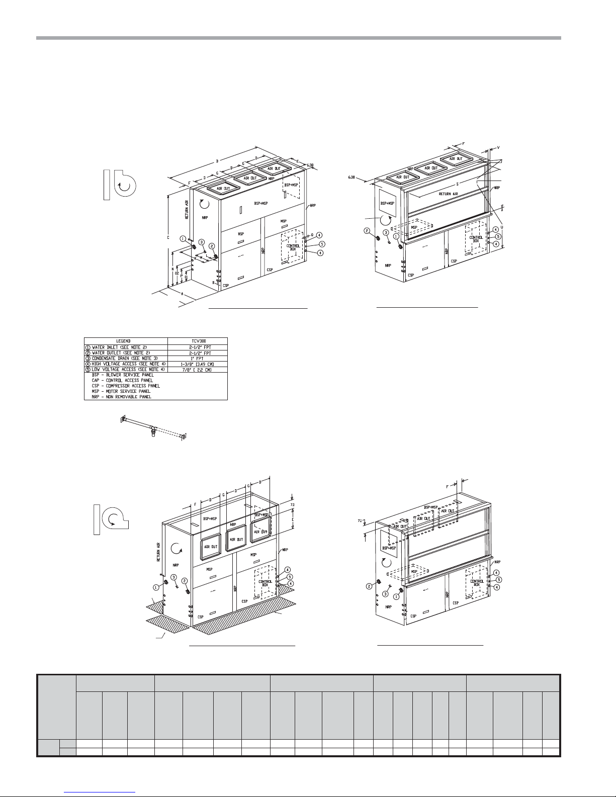
TCV300 Dimensional Data
ALL CONFIGURATIONS REQUIRE SERVICE ACCESS AREA
BLOWER TO AIR COIL
RELATIONSHIP FOR
TOP DISCHARGE
300
(See Note 6)
(See Note 5)
Note 2
ALL CONFIGURATIONS
DESCRIBED IN NOTES 7, 8, and 9
BLOWER
ROTATION
REAR RETURN TOP DISCHARGE (RR/TD)
NOTES:
All dimensions in table are inches (cm)
1. While access to all removable panels may not be required, installer should take care
to comply with all building codes and allow adequate clearance for future field service.
2. Water inlet and water outlet connections are factory shipped on the left side. Union
allows field conversion to right side.
3. Condensate drain is available on either side (left or right) of unit. Drain hose and drain
connection will be tied inside the unit. Installer will untie the drain hose, form trap, and
FRQQHFWWRWKHFRQGHQVDWHGUDLQKROHRILQVWDOOHU·VFKRLFH
4. Electrical access is available on either side (left or right) of unit and is also available in
the front on the left or right side of the unit.
5. Overall width - Add 3.12” (8cm) for 1“ (2.5cm) or 2” (5cm) Filter Frame; or 5.12” (13cm)
for 4” (10.2cm) and for front or rear supply add additional 1.06” (2.7cm) for supply
duct collar.
6. Overall cabinet height dimension does not include duct flange for top discharge
configuration.
8QLWVUHTXLUHIHHWFPFOHDUDQFH&$3&63063DQG%63VHUYLFHDFFHVV
6LGHVHUYLFHDFFHVVPXVWEHIHHWFPRQDQ\VLGHWKDWFRQQHFWLRQVDUHPDGH
)LOWHUUHPRYDOLVIURPULJKWRUOHIWVLGHRIILOWHUIUDPHDOORZIHHWFPDFFHVV
for servicing.
FRONT RETURN TOP DISCHARGE (FR/TD)
BLOWER TO AIR COIL
RELATIONSHIP FOR
REAR OR FRONT
DISCHARGE 300 ONLY
See Notes
1 and 7
SIDE SERVICE
Overall Cabinet
A
ACCESS
(See Notes 8)
REAR RETURN FRONT DISCHARGE (RR/FD)
Discharge Connection Duct
Flange
D
E
Model
DepthB WidthC Height
in. 29.0 82.0 69.8 17.5 14.8 6.3 8.6 25.7 3.1 14.5
300
cm. 73.7 208.3 177.2 44.5 37.5 16.0 21.8 65.3 7.9 36.8
14
Supply
Width
Supply
Depth
SERVICE ACCESS
·&0
FRONT AND BACK
(See Notes 1 and 7)
Water Connections Electrical Knockouts
F
Supply
Width
G
Supply
Depth
K
Water
Inlet
L
Water
Outlet
Conden-
M
sate
N
25.8
65.5
20.3 38.1 28.6 2.5 3.8 195.6 90.9 80.5 6.7
ClimateMaster Water-Source Heat Pumps
FRONT RETURN REAR DISCHARGE (FR/RD)
Return Air Connections
Using Return Air Opening
O 1 O 2 P Q R
S
Return
Depth
Return
Height
U V
T
8.0 15.0 11.3 1.0 1.5 77.0 35.8 31.7 2.6

THE SMART SOLUTION FOR ENERGY EFFICIENCY
Tranquility
TCV 300 with WaterSide Economizer
Overall Cabinet
A
Model
DepthB WidthC Height
in. 39.5 82.0 69.8 17.5 14.8 6.3 8.6 25.7 3.1 14.5
300
cm. 100.3 208.3 177.2 44.5 37.5 16.0 21.8 65.3 7.9 36.8
DFGDG
E
6.40
Top View
Rear Return Top Discharge
Discharge Connection Duct
D
Supply
Width
Flange
E
Supply
Depth
D
F
Supply
Width
G
K
Supply
Water
Depth
Inlet
Legend
BSP = Blower Service Panel
CSP = Compressor Service Panel
CAP = Control Access Panel
MSP = Motor Service Panel
ACP = Aquastat Controller Panel
WSE = Waterside Economizer
EAP = Expansion Valve Access Panel
®
Compact Belt Drive (TCH/V) Series
Water Connections Electrical Knockouts
L
Water
Outlet
M
Conden-
sate
O 1 O 2 P Q R
N
25.8
8.0 15.0 11.3 1.0 1.5 77.0 35.8 31.7 2.6
65.5
20.3 38.1 28.6 2.5 3.8 195.6 90.9 80.5 6.7
Rear Return Front Discharge
Rev.: July 25, 2017
Return Air Connections
Using Return Air Opening
S
Return
Return
Depth
Height
B
BSP
Note 2
U V
T
Top View
7.089
WSE air coil
bleed acces
C
MSP, EAP
Note 2
MSP
Note 2
CAP
CSP
Note 2
Front View
CSP, ACP
Note 2
Q
Rear Return Front Discharge
Notes:
1. While clear access to all removable panels may not be
required, installer should take care to comply with all building
codes and allow adequate clearance for future field service.
2. Units require 3 feet (91 cm) clearance for water connections,
WSE coil air bleed, CAP, CSP, BSP, ACP, and MSP.
SV
T
U
N
O2
P
O1
Back View
Rear Return Front Discharge
3. Factory supplied controller (aquastat) is inside unit completely
wired. To field adjust temperature setting remove ACP panel and push button.
4. Internally trapped, externally vented.
5. For top discharge units, BSP is on front. For front discharge units, BSP is on
top. (allow 3 feet above unit for service).
R
L
MSP
Note 2
M
A
WSE
Right
Side
View
K
climatemaster.com
15
CLIMATEMASTER WATER-SOURCE HEAT PUMPS
Tranquility
Rev.: July 25, 2017
®
Compact Belt Drive (TCH/V) Series
Horizontal Installation
Horizontal Unit Location - Units are not desig ne d for
outdoor in s t alla tio n. Locate the unit in an INDOOR
area that allows en oug h s pac e for s ervice personne l
to perf or m typical maintenance or re pairs without
removing unit f rom t he c eiling. H or izon t al uni t s a re
typic a lly in s t alle d a bove a f al se c eiling o r in a ceili ng
plenum. Never in s t all u nits in areas subjec t to f reezing or where humid ity levels could cause cabinet
condens at ion (s uc h a s un con di tio ne d s pac es s u bject
to 100% ou t sid e air). Con sid er a tion s ho uld b e gi ven
to access fo r ea sy re mov al of t he fi lter and access
panels. Provide s u ffi cient room to make wa ter, elec-
trical, and d uct connecti on(s). Allow 3 feet (91 c m)
clearance fo r se rvicing unit through all ac ce s s pa nel s.
If the unit is lo c a ted in a c onfi ned spa ce, su ch a s a
closet, prov isio ns m ust be made for return air to f reel y
enter the s pac e by mean s of a l ou vere d do or, etc. Any
access pa nel s c rew s t hat w ould b e di ffi cult to remove
after t he u ni t is i nstalled should be remove d pr ior to
sett ing t he un it . Refer to Fig ure 3 fo r an ill ustration of a
typic a l in s t allatio n. Refer to u nit s ub mi ttal data or engineering de sign g uid e fo r dim en sional d at a.
Conform to the following guidelines when selecting
unit location:
1. Provide a hinged access door in concealed-spline
or plaster ceilings. Provide removable ceiling
tiles in T-bar or lay-in ceilings. Refer to horizontal
unit dimensions f or specifi c series and model
in unit submittal data. Size the access opening
to accommodate the service technician during
the removal or replacement of the compressor,
control, or blower assembly.
to hanger brackets, water valves and fi ttings.
Provide screwdriver clearance to access panels,
discharge collars and all electrical connections.
2. DO NOT obstruct the space beneath the unit with
piping, electrical cables and other items that prohibit
future removal of components or the unit itself.
3. Use a manual portable jack/lift to lift and support the
weight of the unit during installation and servicing.
The installation of water source heat pump units and all
associated components, parts and accessories which
make up the installation shall be in accordance with
the regulations of ALL authorities having jurisdiction
and MUST conform to all applicable codes. It is the
responsibility of the installing contractor to determine
and comply with ALL applicable codes and regulations.
Provide access
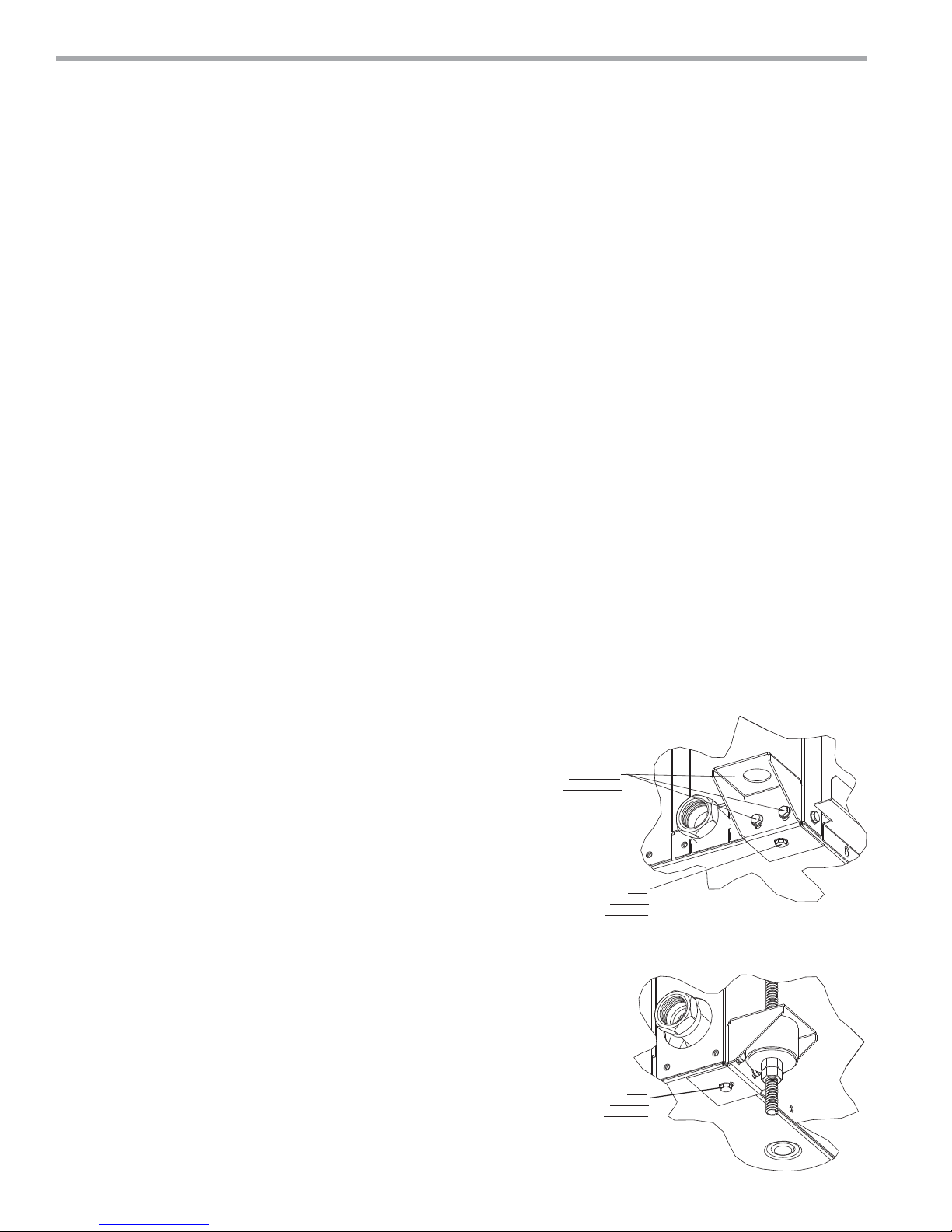
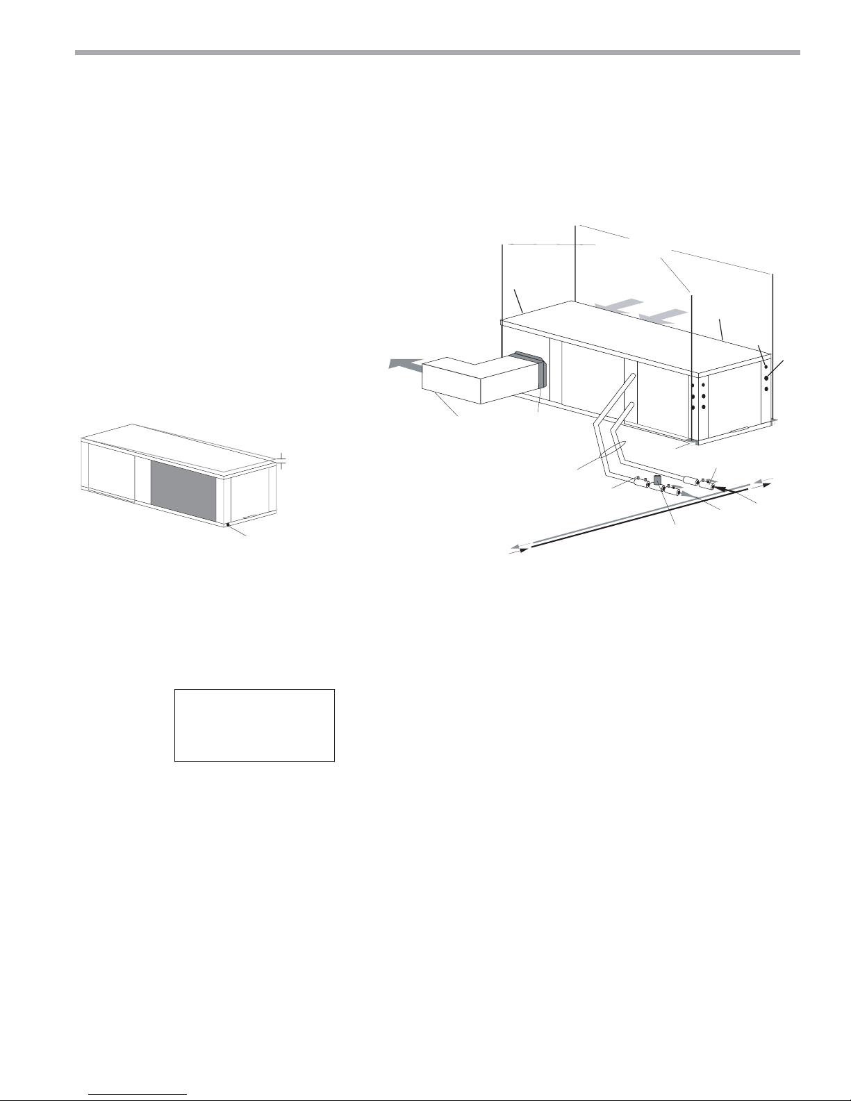
Mounting Horizontal Units
Horizontal units have 4 hanger brackets partially attached
at the factory, one at each corner. Enclosed within the
unit there is a hanger kit hardware bag containing
vibration isolation grommets, washers, screws and a
hanger installation instruction page. One additional
screw from the hardware bag must be added to each
hanger bracket before unit installation.Tighten each
screw to 75 in-lbs (8.5 Nm). See Figure 1. Refer to
the hanger installation instruction page contained in
the hardware bag for details of fi nal hanger bracket
attachment and unit suspension. See Figure 1a.
Use four (4) fi eld supplied threaded rods and factory
provided vibration isolators to suspend the unit. Safely
lift the unit into position supporting the bottom of the
unit. Ensure the top of the unit is not in contact with any
external objects. Connect the top end of the 4 all-thread
rods, slide rods through the brackets and grommet then
assemble washers and double nuts at each rod. Ensure
that the unit is approximately level and that the threaded
rod extends past the nuts.
Pitch the unit toward the drain as shown in Figure 2 to
improve the condensate drainage.
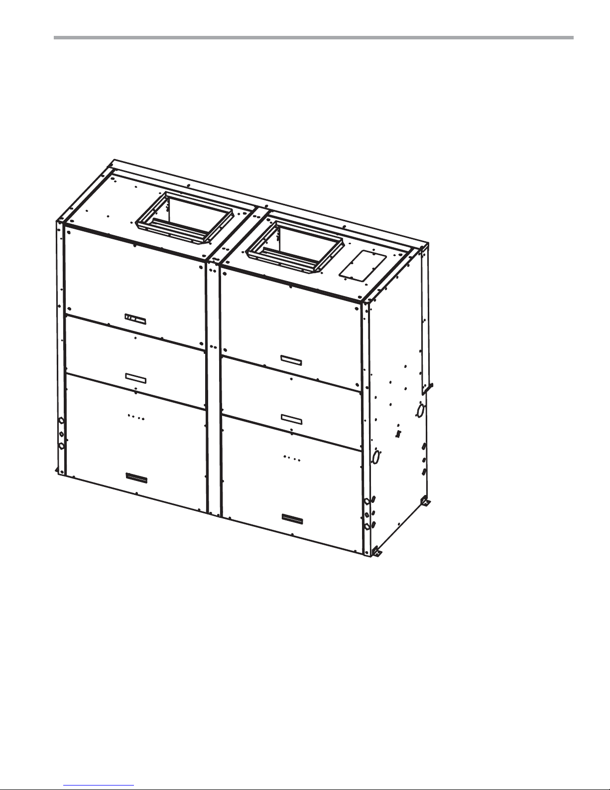
Figure 1: Hanger Bracket
INSTALLED
AT FACTORY
ADD
BEFORE
HANGING
VIEW CONDENSATE END
BEFORE GROMMET AND HARDWARE
(Unit pictured for hanger bracket reference).
(Drain hardware may vary per unit model)
Figure 1a:
ADD
BEFORE
HANGING
VIEW WATER CONNECTION END
FULLY ASSEMBLED
(Unit pictured for hanger bracket reference)
(Water hardware may vary per unit model)
16
ClimateMaster Water-Source Heat Pumps
THE SMART SOLUTION FOR ENERGY EFFICIENCY
(by others)
Thermostat
Wiring
Insulated supply duct with
at least one 90 deg elbow
to reduce air noise
Return Air
Supply Air
Unit Hanger
3/8" [10mm] threaded rods
Flexible Duct
Connector
LEGEND
CAP=Compressor Access Panel
CBP=Control Box Panel
BSP=Blower Service Panel
EAP=Expansion Valve Access panel
1=Water Outlet 1-1/4” FPT (072-096) 1-1/2” FPT (120)
2=Water Inlet 1-1/4” FPT (072-096) 1-1/2” FPT (120)
3=Condensate 3/4” FPT
4=High Voltage 1-1/8” [2.9cm] KO
5=Low Voltage 7/8” [2.2cm] KO
Figure 2: Horizontal Unit Pitch
Drain Connection
1/4” (6.4mm) pitch
toward drain for drainage
Tranquility
Figure 3: Typical Horizontal Unit Installation
®
Compact Belt Drive (TCH/V) Series
Rev.: July 25, 2017
BSP
CBP
EAP
CAP
Ball valve with optional
integral P/T plug
Water In
Water Out
Building
Loop
Stainless steel braid hose
with integral “J” swivel
Optional
Balancing Valve
CAP
Optional Low Pressure Drop Water
Control Valve
Unit
Power
Air Coil - To obtain maximum performance, the air coil
should be cleaned before start-up. A 10% solution of
dishwasher detergent and water is recommended for
both sides of the coil. A thorough water rinse should
follow. UV based anti-bacterial systems may damage
coated air coils.
NOTES:
-
All dimensions in table are inches (cm).
6HUYLFHDccess is required for all removable panels and installer should take care to comply with all building codes and
allowadequate clearance for future field service.
Water inlet and water outlet connections are available on either side (left or right) of the unit. Qty (2x) MPT Plugs are
shipped loose in a plastic bag tied to the water leg in front of the unit. Installer must plug water inlet/outlet side not being
connected to.
&RQGHQVDWHGUDLQLV)37DQGLVORFDWHGRQFDELQHWHQGRSSRVLWHWKHFRPSUHVVRU
Electrical access is available on either side (left or right) of the front.
Electric box is on right side. It can be field converted to left side. Conversion should only be attempted by qualified
service technician. If electric box relocated to opposite side, and water connected to opposite side, then this access is
not required.
Units require 3’ (9.1 cm) clearance for water connections, CAP, C%P, EAP and BSP service access.
Overall cabinet width dimensions does not include filter rail and duct flange.
8QLWVDUHVKLSSHGZLWKDLUILOWHUUDLOVWKDWDUHQRWVXLWDEOHIRUVXSSRUWLQJUHWXUQDLUGXFWZRUN$QDLUILOWHUIUDPHZLWKGXFW
PRXQWLQJFROODULVDYDLODEOHDVDQDFFHVVRU\
Notice! Installation Note - Ducted Return: Many
horizontal WSHPs are installed in a return air ceiling
plenum application (above ceiling). Vertical WSHPs are
commonly installed in a mechanical room with free return
(e.g. louvered door). Therefore, fi lter rails are the industry
standard and are included on ClimateMaster commercial
heat pumps for the purposes of holding the fi lter only.
For ducted return applications, the fi lter rail must be
removed and replaced with a duct fl ange or fi lter frame.
Canvas or fl exible connectors should also be used to
minimize vibration between the unit and ductwork.
climatemaster.com
17

CLIMATEMASTER WATER-SOURCE HEAT PUMPS
Step 2
Loosen 2 motor slide nuts,
raise slide assembly, remove
Step 1
R
a
Remove blower panel
and access panel
Return air
Front
Step 3
Remove motor
and blower
Adjusting bolt used to raise or
lower motor slide
Remove 4
motor bolts
Tranquility
Rev.: July 25, 2017
®
Compact Belt Drive (TCH/V) Series
TCH Field Conversion of Air Discharge
WARNING!
WARNING! To avoid possible injury or death due to
electrical shock, open the power supply disconnect switch
and secure it in an open position during installation or
conversion.
Overview -
between straight (side) and back (end) discharge using
the instructions below.
Note: It is not possible to fi eld convert return air
between left or right return models due to the
necessity of refrigeration copper piping changes.
Preparation - Field conversion must be completed on
the ground. If the unit is already hung it should be taken
down for the fi eld conversion. Place in a well-lighted
area. Conversion should only be attempted by a qualifi ed
service technician.
Horizontal units can be fi eld converted
Figure 4: Left Return Side Discharge to Back
Side to Back Discharge Conversion
1. Remove back panel and side access panel
2. Loosen 2 motor slide nuts, raise motor slide assembly
and remove belt and motor sheave.
3. Remove blower sheave. Remove motor bolts and
carefully remove motor.
4. Remove 2 motor clips and reattach to opposite side.
5. Unbolt (3 per side) complete housing assembly.
6. Rotate complete assembly into new position. Locate
over mounting holes in base, reattach using 3 bolts per
side.
7. Mount motor, motor sheave, blower sheave and belt.
Make sure wires are not pinched and not over sharp
edges. Adjust motor downward to tighten belt. Raise
or lower motor slide assembly with adjusting bolt
and retighten 2 slide nuts. Check for correct tension
(See Tensioning V-Belt Drives page). Rewire motor (at
contactor) for correct rotation. Spin blower wheel to
ensure wheel is not obstructed.
8. Replace 2 panels.
Back to Side Discharge Conversion - If the discharge is
changed from back to side, use above instruction noting
that illustrations will be reversed.
Left vs. Right Return - It is not possible to fi eld convert
return air between left or right return models due to the
necessity of refrigeration copper piping changes. However,
the conversion process of side to back or back to side
discharge for either right or left return confi guration is
the same. In some cases, it may be possible to rotate the
entire unit 180 degrees if the return air connection needs
to be on the opposite side. Note that rotating the unit will
move the piping to the other end of the unit.
18
ClimateMaster Water-Source Heat Pumps
Figure 4 Continued on Following Page
THE SMART SOLUTION FOR ENERGY EFFICIENCY
Remove (3x) per slide
1/4-20 UNC bolts
Step 5
Step 6
Rotate entire blower housing assembly to rest at back end of the
unit. Locate housing holes and bolt down using previous 1/4-20
UNC bolts (3x) ea. side.
Motor motor, motor sheave,
blower sheave and belt
Step 7
Step 8
Put blower panel
and access panel back on
Return air
Front
Return air
Step 4
Move motor clips to
other side on bracket
Tranquility
Figure 4 Continued: Left Return Side Discharge to Back
®
Compact Belt Drive (TCH/V) Series
Rev.: July 25, 2017
climatemaster.com
19
CLIMATEMASTER WATER-SOURCE HEAT PUMPS
ರ
ರ
ರ
* Some units include a painted drain connection.
Using a threaded pipe or similar device to clear
any excess paint accumulated inside this fitting
may ease final drain line installation.
ರ3HU
)RRW
Condensate Piping
July 25, 2017
n
Tranquility
Rev.: July 25, 2017
.:
®
Compact Belt Drive (TCH/V) Series
Duct System Installatio
Horizontal Installation
Figure 5: Right Return Side Discharge to Back
RIGHT RETURN SIDE DISCHARGE
CBP
RETURN AIR
Drain
FRONT
RIGHT RETURN END DISCHARGE
FRONT
CBP
RETURN AIR
Drain
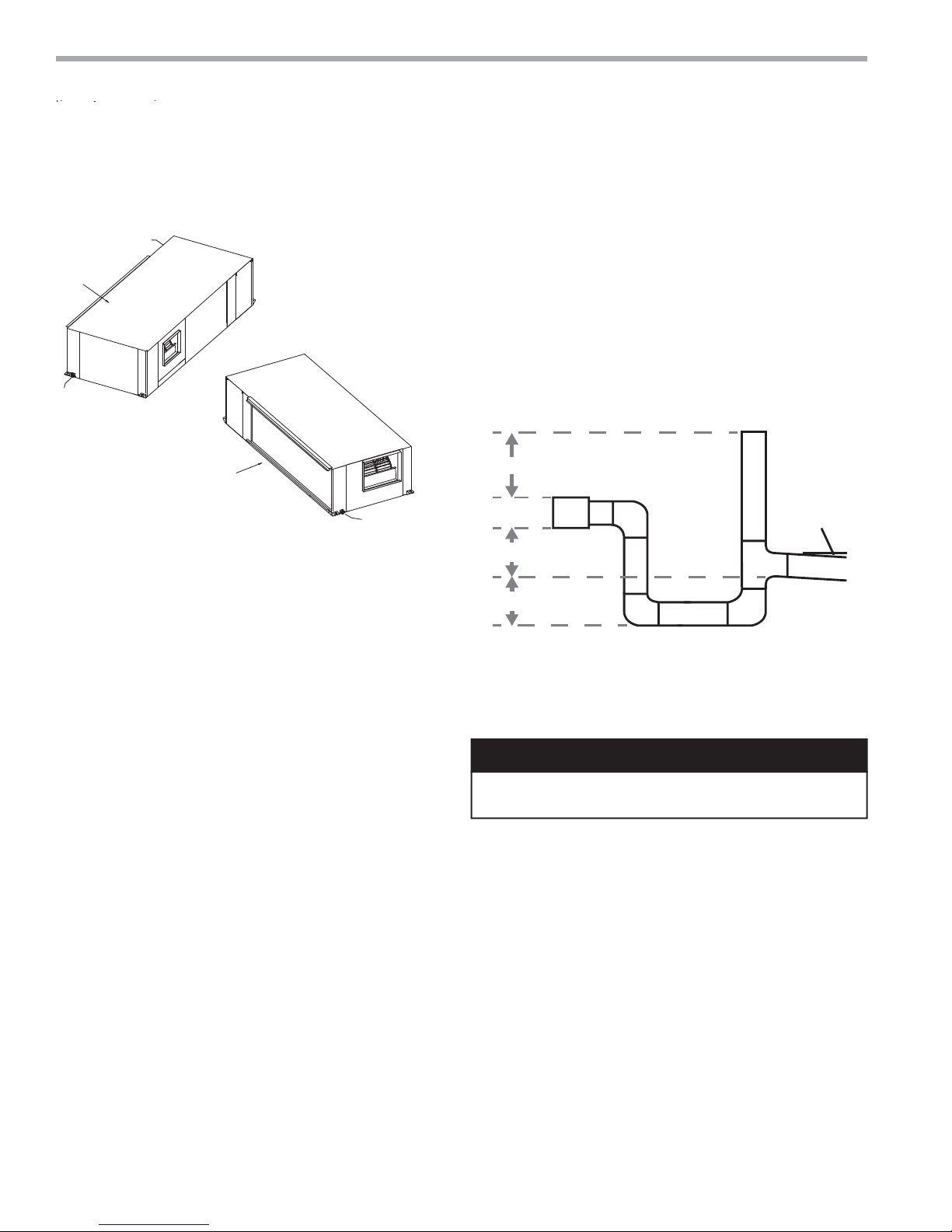
Always vent the condensate line when dirt or air
can collect in the line or a long horizontal drain line
is required. Also vent when large units are working
against higher external static pressure than other units
connected to the same condensate main since this may
cause poor drainage for all units on the line. WHEN A
VENT IS INSTALLED IN THE DRAIN LINE, IT MUST BE
LOCATED AFTER THE TRAP IN THE DIRECTION OF
THE CONDENSATE FLOW.
Figure 6: Horizontal Condensate Connection
Horizontal Units Condensate Piping - Pitch the unit
toward the drain as shown in Figure 2 to improve the
condensate drainage. Ensure that unit pitch does not
cause condensate leaks inside the cabinet.
Install condensate trap at each unit with the top of
the trap positioned below the unit condensate drain
connection as shown in Figure 6. Design the depth of the
trap (water-seal) based upon the amount of ESP capability
of the blower (where 2 inches [51mm] of ESP capability
requires 2 inches [51mm] of trap depth). As a general rule,
1-1/2 inch [38mm] trap depth is the minimum.
Each unit must be installed with its own individual trap
and connection to the condensate line (main) or riser.
Provide a means to fl ush or blow out the condensate line.
DO NOT install units with a common trap and/or vent.
Duct System Installation - Proper duct sizing and design
is critical to the performance of the unit. The duct system
should be designed to allow adequate and even airfl ow
through the unit during operation. Air fl ow through
the unit MUST be at or above the minimum stated
airfl ow for the unit to avoid equipment damage. Duct
systems should be designed for quiet operation. Refer
to Figure 3 for horizontal duct system details or Figure
8 for vertical duct system details. A fl exible connector
is recommended for both discharge and return air duct
connections on metal duct systems to eliminate the
transfer of vibration to the duct system. To maximize
20
CAUTION! Ensure condensate line is pitched toward drain
1/8 inch per ft [11mm per m] of run.
DUCT SYSTEM INSTALLATION
sound attenuation of the unit blower, the supply and
return plenums should include internal fi berglass duct
liner or be constructed from ductboard for the fi rst few
feet. Application of the unit to uninsulated ductwork in an
unconditioned space is not recommended, as the unit’s
performance may be adversely affected.
At least one 90° elbow should be included in the supply
duct to reduce air noise. If air noise or excessive air fl ow
is a problem, the blower speed can be changed. For
airfl ow charts, consult submittal data for the series and
model of the specifi c unit.
ClimateMaster Water-Source Heat Pumps
CAUTION!
THE SMART SOLUTION FOR ENERGY EFFICIENCY
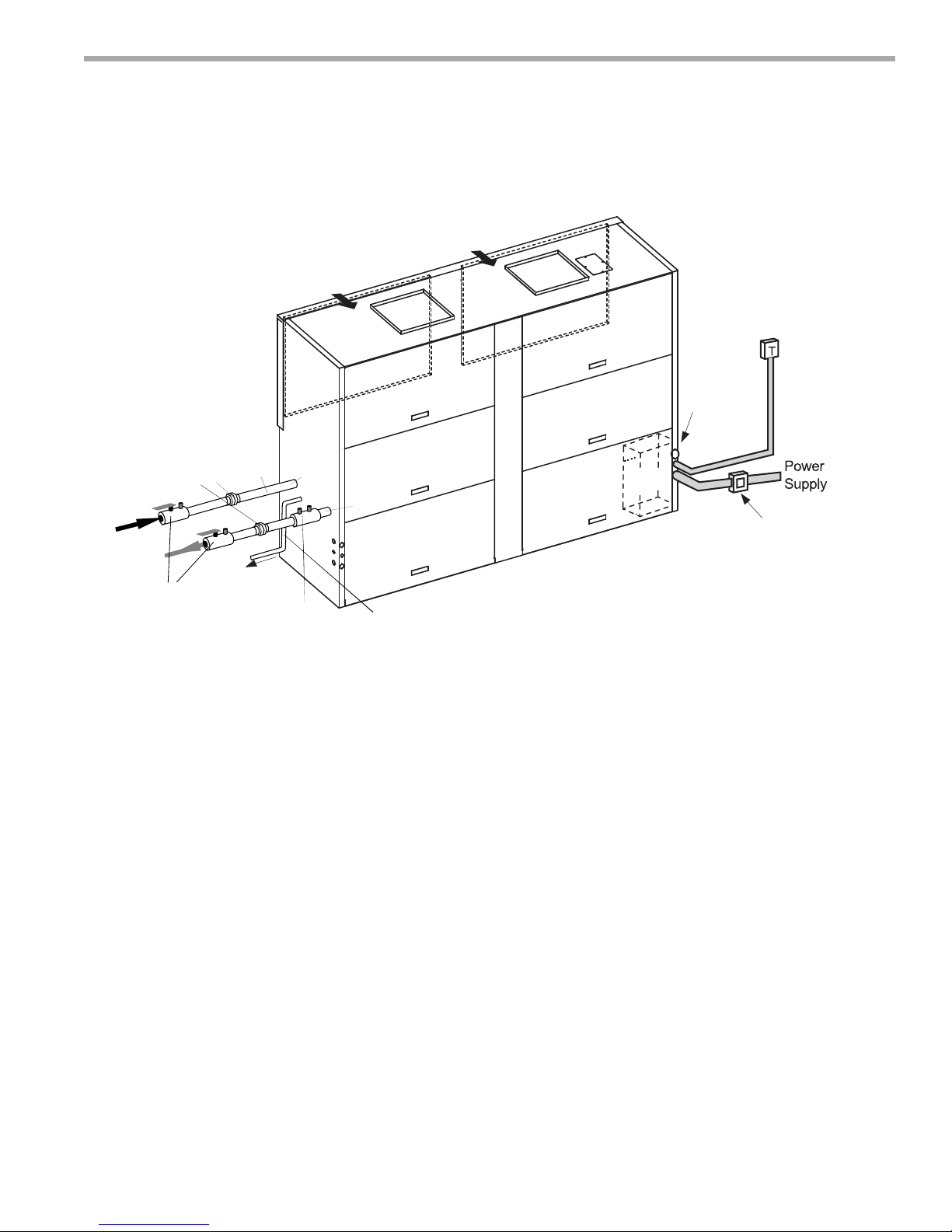
Figure 7: Typical Vertical Installation
Rear Return/Top Discharge shown
Refer to Dimensional Data pages for
other arrangements & dimensions
Ductwork not shown.
All components external
of unit are field supplied.
Unions
Supply
Water
Return
Water
Shutoff
(See Figure
10 for Vent)
Hoses
Optional
To
Drain
Return Air
Water
In
Optional
Balancing
Valve
Tranquility
Return Air
Supply
Air
Water
Out
Condensate Internally
Trapped. Do not trap externally.
Pitch horizontal runs ¼” per foot.
®
Supply
Air
Compact Belt Drive (TCH/V) Series
Rev.: July 25, 2017
Vertical Installation
24 V Remote
Thermostat
Plug water
in and out
connections
Control
Box
Disconnect Box
Per NEC and
Local Codes
Vertical Location and Access
TC units are not designed for outdoor installation. Locate
the unit in an indoor area that allows enough space for
installation and for service personnel to perform typical
maintenance or repairs. TC units are typically installed in
a fl oor level closet or in a small mechanical room. Refer to
Figure 7 for an illustration of a typical installation. Install
units with adequate clearance to allow maintenance and
servicing. Conform to the following guidelines when
selecting unit location:
• Provide adequate clearance for filter replacement and
drain pan cleaning. DO NOT block filter access with
piping, conduit or other materials. Refer to submittal
drawing for Vertical Unit Dimensions.
• Provide access for fan and fan motor maintenance
and for servicing of the compressor and coils without
removal of the unit.
• Provide an unobstructed path to the unit within the
closet or mechanical room to enable removal of the
unit if necessary.
• Provide access to water valves and fittings, and
screwdriver access to the unit side panels, discharge
collar and all electrical connections
Duct System Design & Installation Guidelines
The following application guidelines must be used
when installing TC units. Failure to follow these guidelines could result in unsatisfactory unit performance
and/or premature failure of some unit components.
ClimateMaster will not warrant, or accept responsibility
for products which fail, have defects, damage or insuffi -
cient performance as a result of improper application.
• The duct system must be sized to handle the
airflow quietly and must not exceed the maximum
allowable External Static Pressure. To maximize
sound attenuation metal supply and return ducts
should include internal insulation or be of duct board
construction for the first 10 feet or end of first full-sized
elbow.
• Install a flexible connector in all supply and return
air ducts close to the unit to inhibit sound transfer to
the ducts.
• Do not install uninsulated duct in an unconditioned
space. The unit performance will be adversely affected
and damage from condensate can occur.
climatemaster.com
21

CLIMATEMASTER WATER-SOURCE HEAT PUMPS
Tranquility
Rev.: July 25, 2017
®
Compact Belt Drive (TCH/V) Series
TCV Field Conversion of Air Discharge
WARNING!
WARNING! To avoid possible injury or death due to
electrical shock, open the power supply disconnect switch
and secure it in an open position during installation or
conversion.
Overview -
top and straight (side) and back (end) discharge using the
instructions below.
Preparation - Place in a well-lighted area. Conversion
should only be attempted by qualifi ed service technicians.
Vertical units can be fi eld converted between
22
ClimateMaster Water-Source Heat Pumps
THE SMART SOLUTION FOR ENERGY EFFICIENCY
Tranquility
®
Compact Belt Drive (TCH/V) Series
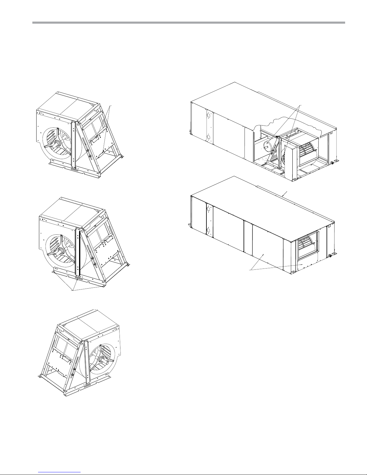
TCV072-240 Field Conversion of Air Discharge
Figure 8: TCV072 - 120 and TCV160-240 Pictorally Shown Top Discharge Steps to Convert
to Straight Discharge
Rev.: July 25, 2017
Step 1 - For TCV072-120 remove 3 panels.
For TCV160-240 remove 6 panels, middle
climatemaster.com
23

CLIMATEMASTER WATER-SOURCE HEAT PUMPS
y
Tranquility
Rev.: July 25, 2017
®
Compact Belt Drive (TCH/V) Series
TCV072-240 Field Conversion of Air Discharge
Upper Mount
Holes for Top
Discharge
(2X) Bolts
Step 2 - Remove motor and then unscrew and
remove motor mount assembly. Put motor
mount assembl
back in lower mount position.
Lower Mount
Holes for
Straight
Discharge
(2X) Bolts
24
ClimateMaster Water-Source Heat Pumps
 Loading...