

ClimateMaster TAH Series, TAH 026-A, TAH 038-B, TAH 026-B, TAH 049-B Installation, Operation & Maintenance Instructions Manual
...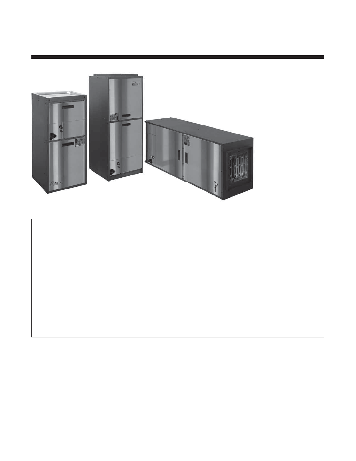
Tranquility Air Handler (TAH)
Tran
l
e
Air Handler for
Tranquility Split Series
Installation, Operation &
Insta
Maintenance Instructions
aint
97B0101N01
Rev: 5/2/12
Table of Contents
Model Nomenclature 3
General Information 4
Pre-Installation 4
Safety 5
Physical Data 6
Dimensional Data 7
Installation 8-13
Electrical - Thermostat Wiring 14
ECM Blower Control 15-16
Electrical - Power Wiring 17
Electrical Table 17
Wire Diagram 18
Blower Data 19
Electric Heat Installation 20
Electric Heat Wiring 21-22
Electric Heat Staging Options 23
Unit & System Checkout 24
Maintenance 24
Warranty 25
Revision History 26

Tranquility Air Handler (TAH)
Rev.: May 2, 2012
This page was intentionally left blank.
2
Geothermal Heat Pump Systems
Tranquility Air Handler (TAH)
Rev.: May 2, 2012
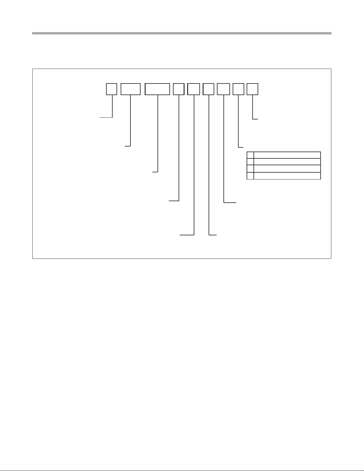
Model Nomenclature
MODEL TYPE
T = TRANQUILITY R410A
CONFIGURATION
AH = AIR HANDLER
NOMINAL CAP ACITY
026
038
049
064
2 31 4 5 6
A HT 0 2 6
REVISION
A = CURRENT REVISION
VOLTAGE
G = 208-230/60/1
( NOTE; FIELD CONVERTIBLE TO 1 15v )
7
A
8
G
9
S
10
11
M
A
CABINET OPTIONS
M = MULTI-POSITION
CONTROLS
S = STANDARD
12
S
FUTURE USE
S = STANDARD
CABINET SIZE
(WIDTH, INCHES)
SIZE 026 ONLY ; 18.5 WIDTH
A
SIZES 026, 038, 049 ONLY ; 22.5 WIDTH
B
SIZES 038, 049, 064 ; 25.5 WIDTH
C
3
Tranquility Air Handler (TAH)
Rev.: May 2, 2012
General Information
Air Handler Description
ClimateMaster Tranquility Air Handlers are designed for
use with ClimateMaster indoor/outdoor split units and are
available for vertical upfl ow or downfl ow, and horizontal left
or horizontal right airfl ow.
• Air coils are constructed of aluminum fi ns bonded to
internally grooved copper tubing.
• Air coils are tested at the factory with an extensive
refrigerant leak check.
• Air coils have sweat refrigerant connections.
• Ideally suited for new installations or add on air
conditioning.
• Feature two sets of 3/4” [14.1 mm] F.P.T. Condensate
drain connections for ease of connection.
• Air Handlers are A.H.R.I. certifi ed for system application
with ClimateMaster indoor and outdoor split units.
• Condensate drain pan is constructed of high grade, heat
resistant, corrosion free thermal-set material.
• Bi-Directional airfl ow eliminates the need to switch any
internal components from horizontal left to right.
• Unique drain pan design maximizes application fl exibility
and condensate removal.
Inspection
Upon receipt of the equipment, carefully check the shipment
against the bill of lading. Make sure all units have been
received. Inspect the packaging of each unit, and inspect each
unit for damage. Insure that the carrier makes proper notation
of any shortages or damage on all copies of the freight bill and
completes a common carrier inspection report. Concealed
damage not discovered during unloading must be reported
to the carrier within 15 days of receipt of shipment. If not fi led
within 15 days, the freight company can deny the claim without
recourse. Note: It is the responsibility of the purchaser to fi le
all necessary claims with the carrier. Notify your equipment
supplier of all damage within fi fteen (15) days of shipment.
Storage
Equipment should be stored in its original packaging in a
clean, dry area. Store units in an upright position at all times.
Stack units a maximum of 3 units high.
Unit Protection
Cover units on the job site with either the original packaging
or an equivalent protective covering. Cap the open ends of
pipes stored on the job site. In areas where painting, plastering,
and/or spraying has not been completed, all due precautions
must be taken to avoid physical damage to the units and
contamination by foreign material. Physical damage and
contamination may prevent proper start-up and may result in
costly equipment clean-up.
are provided with each unit. Horizontal equipment is
designed for installation above false ceiling or in a ceiling
plenum. Other unit confi gurations are typically installed
in a mechanical room. The installation site chosen should
include adequate service clearance around the unit. Before
unit start-up, read all manuals and become familiar with the
unit and its operation. Thoroughly check the system before
operation.
Prepare units for installation as follows:
1. Compare the electrical data on the unit nameplate with
ordering and shipping information to verify that the
correct unit has been shipped.
2. Keep the cabinet covered with the original packaging
until installation is complete and all plastering, painting,
etc. is fi nished.
3. Verify refrigerant tubing is free of kinks or dents and that
it does not touch other unit components.
4. Inspect all electrical connections. Connections must be
clean and tight at the terminals.
WARNING!
WARNING! These instructions are intended as an aid to
qualifi ed licensed service personnel for proper installation,
adjustment and operation of this unit. Read these
instructions thoroughly before attempting installation
or operation. Failure to follow these instructions may
result in improper installation, adjustment, service or
maintenance possibly resulting in property damage,
personal injury or death.
CAUTION!
CAUTION! DO NOT store or install units in corrosive
environments or in locations subject to temperature
or humidity extremes. Corrosive conditions and high
temperature or humidity can signifi cantly reduce
performance, reliability, and service life.
CAUTION!
CAUTION! CUT HAZARD - Failure to follow this caution
may result in personal injury. Sheet metal parts may have
sharp edges or burrs. Use care and wear appropriate
protective clothing, safety glasses and gloves when
handling parts and servicing.
Examine all pipes, fi ttings, and valves before installing any of
the system components. Remove any dirt or debris found in
or on these components.
Pre-Installation
Installation, Operation, and Maintenance instructions
4
Geothermal Heat Pump Systems
Tranquility Air Handler (TAH)
Rev.: May 2, 2012
Safety
The installation of water source heat pump units and all
associated components, parts and accessories which make
up the installation shall be in accordance with the regulations
of ALL authorities having jurisdiction and MUST conform to
all applicable codes. It is the responsibility of the installing
contractor to determine and comply with ALL applicable
codes and regulations.
Replacement Parts
Any replacement part must be the same as or an approved
alternate to the original part supplied. The manufacturer will
not be responsible for replacement parts not designed to
physically fi t or operate within the design parameters the
original parts were selected for. When ordering replacement
parts, it is necessary to order by part number and include
the complete model number and serial number from the coil
rating plate. (See parts list for unit component part numbers.
Parts are available through the local distributor.)
Safety
Warnings, cautions and notices appear throughout this
manual. Read these items carefully before attempting any
installation, service, or troubleshooting of the equipment.
DANGER: Indicates an immediate hazardous situation, which
if not avoided will result in death or serious injury. DANGER
labels on unit access panels must be observed.
CAUTION!
CAUTION! It is recommended that an auxiliary
secondary drain pan be installed under units containing
evaporator coils that are located in any area of a structure
where damage to the building or building contents may
occur as a result of an overfl ow of the coil drain pan or a
stoppage in the primary condensate drain piping.
WARNING!
WARNING! All refrigerant discharged from this unit must
be recovered WITHOUT EXCEPTION. Technicians must
follow industry accepted guidelines and all local, state, and
federal statutes for the recovery and disposal of refrigerants.
To avoid leakage of compressor oil, refrigerant lines of the
compressor must be sealed after it is removed.
CAUTION!
CAUTION! To avoid equipment damage, DO NOT use
these units as a source of heating or cooling during the
construction process. The mechanical components and
fi lters will quickly become clogged with construction dirt
and debris, which may cause system damage.
WARNING: Indicates a poten tiall y hazardous situa tion , which
if not avoided could result in death or serious injury.
CAUTION: Indicates a potentially hazardous situation or an
unsafe practice, which if not avoided could result in minor or
moderate injury or product or property damage.
NOTICE: Notifi cation of installation, operation or maintenance
information, which is important, but which is not hazardrelated.
WARNING!
WARNING! The EarthPure® Application and Service
Manual should be read and understood before
attempting to service refrigerant circuits with HFC-410A.
WARNING!
WARNING! To avoid the release of refrigerant into the
atmosphere, the refrigerant circuit of this unit must be
serviced only by technicians who meet local, state, and
federal profi ciency requirements.
5
Tranquility Air Handler (TAH)
Rev.: May 2, 2012
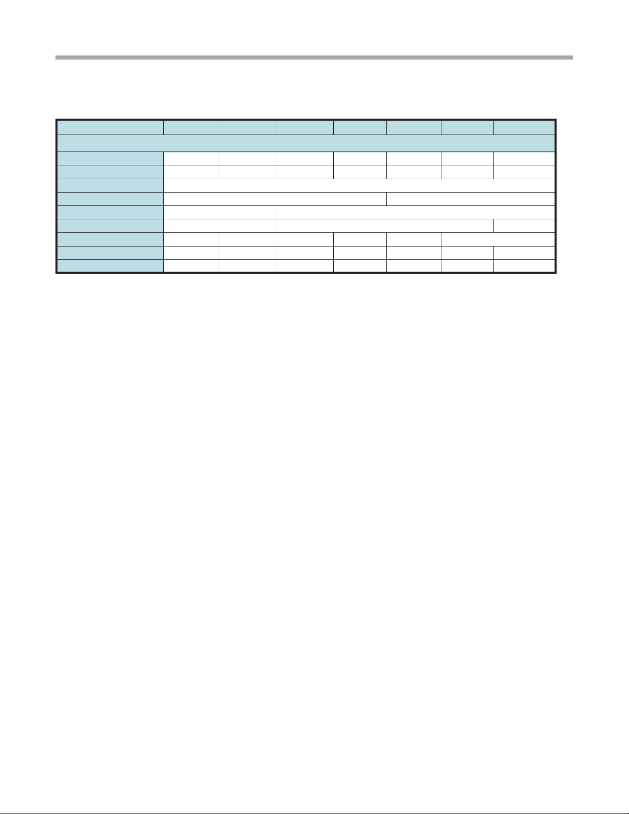
Unit Physical Data
Model 026-A 026-B 038-B 038-C 049-B 049-C 064-C
Emerson ECM Fan Motor & Blower
Liquid I.D. 3/8 3/8 3/8 3/8 3/8 3/8 3/8
Suction I.D. 3/4 3/4 7/8 7/8 7/8 7/8 7/8
Fan Motor Type/Speeds ECM Variable
Fan Motor (hp) 1/2 1
Blower Wheel Size (Dia x W) 9 x 7 12 x 10
Air Coil Dimensions (H x W) 3 - 2 Row 14 x 17 3 - 2 Row 24 x 17 3 - 3 Row 24x17
Filter Standard - 1” Throwaway 16 x 20 20 x 20 20 x 24 20 x 20 20 x 24
Weight - Operating (lbs.) 80 163 173 181 180 188 198
Weight - Packaged (lbs.) 96 179 198 206 218 226 236
6
Geothermal Heat Pump Systems
Tranquility Air Handler (TAH)
Rev.: May 2, 2012
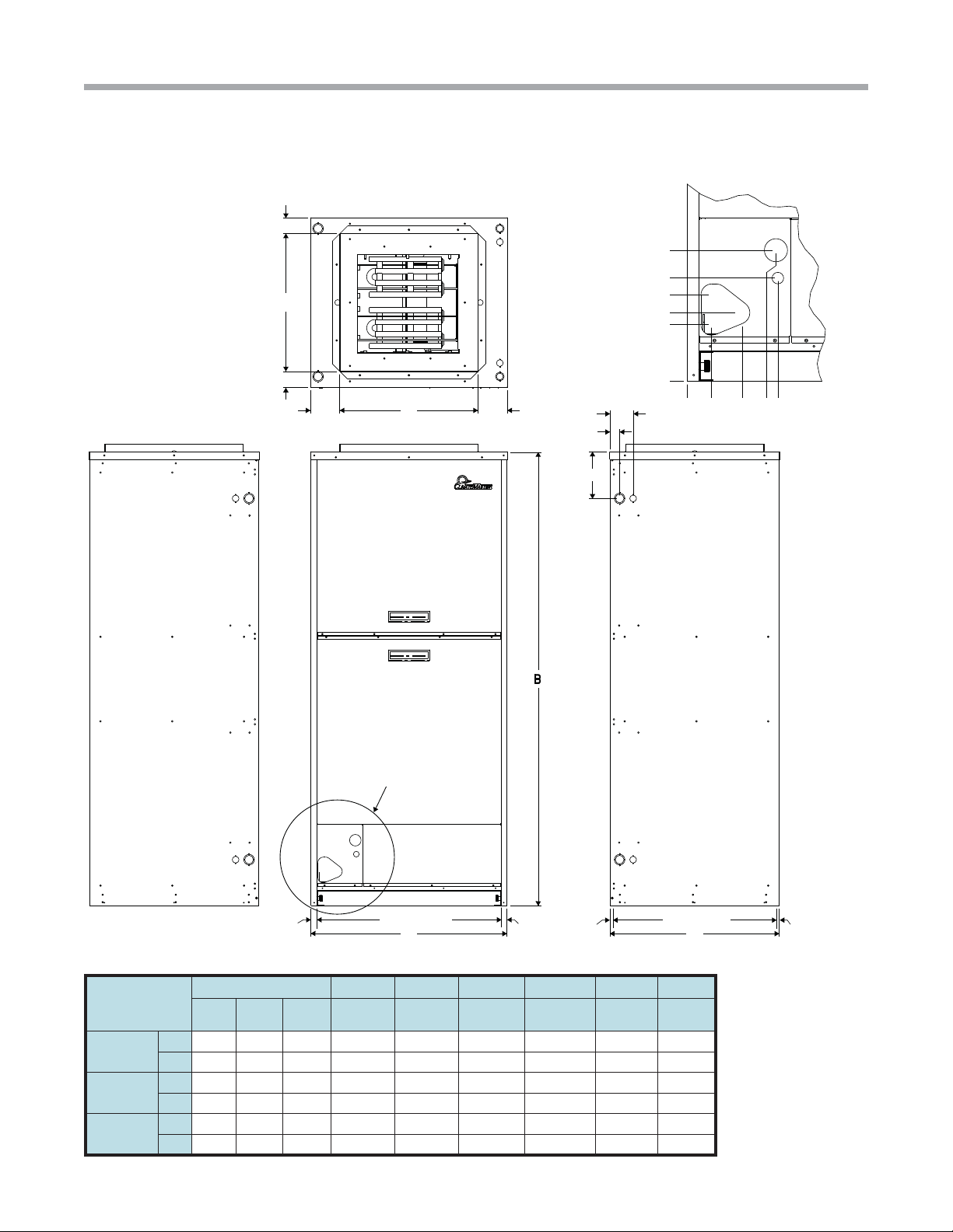
Unit Dimensional Data
J
8.5
6.7
E
5.6
4.5
3.7
H
G
See Detail A
FD
3.
1.3
6.1
0.0
0.0
1.6
3.6
5.8
Detail A
Scale 5/32
5.9
Cabinet
Size
A - Cabinet
B - Cabinet
C - Cabinet
R.A. Opening
A
0.6250.625
R.A. Opening
Overall Cabinet 1 2 3 4 5 6
A
WidthBHeightCDepth
in. 18.5 44.0 22.0 14.0 14.0 2.3 2.3 4.1 4.1
cm. 47.0 111.8 55.9 35.6 35.5 5.8 5.8 10.3 10.3
in. 22.0 55.0 22.0 18.0 18.0 2.1 2.1 2.1 2.1
cm. 55.9 139.7 55.9 45.7 45.7 5.2 5.2 5.2 5.2
in. 25.5 59.0 22.0 18.0 18.0 3.8 3.8 2.1 2.1
cm. 64.8 149.9 55.9 45.7 45.7 9.9 9.9 5.2 5.2
D E F G H J
C
0.8750.75
7
 Loading...