


MPC MULTIPROTOCOL DDC CONTROLS
Application, Operation & Maintenance
97B0031N01
Revised: November 19, 2018

THE SMART SOLUTION FOR ENERGY EFFICIENCY
MPC MultiProtoCol DDC Controls
November 19, 2018
Table of Contents
MPC Controller Overview .................................................................................................. 3-10
BACview6 Service Tool and Addressing ......................................................................... 11-13
Equipment Touch Tool Overview ..........................................................................................14
MPC LED Codes .....................................................................................................................17
MPC Sequence of Operation .......................................................................................... 18-23
Multi-Generation Water-to-Air Point Matrix ................................................................... 24-34
MPC Feature Conguration ............................................................................................. 35-37
Generation 4 Water-to-Water Points Matrix ................................................................... 38-41
MPC Wall Sensors ............................................................................................................ 42-47
Android App Installation ........................................................................................................48
Equipment Touch Manual- Screen Descriptions ............................................................ 50-68
Frequently Asked Questions (FAQs) .....................................................................................49
Revision History ......................................................................................................................72
2

THE SMART SOLUTION FOR ENERGY EFFICIENCY
MPC Controller Overview
MPC MultiProtoCol DDC Controls
November 19, 2018
The Multi-Protocol (MPC) Heat Pump controller is a dual
purpose controller. It contains the logic to perform as an
advanced customizable thermostat when combined with
a wall sensor and is designed to allow the integration of
water source heat pump equipment into DDC systems.
The MPC Controller has the ability to communicate
through a choice of four widely used protocols:
1. BACnet MS/TP
2. Johnson Controls N2
3. Modbus
4. LonWorks.
The protocol of choice for the particular system is
selected by simply conguring DIP switches on the MPC
Controller with the exception of LonWorks. The LonWorks
option requires an additional Lon option card (LOC).
This exibility allows one controller, the MPC, to be used
in a multitude of buildings which use any of these four
common protocols.
The MPC serves as a node of information processing
between the heat pump and the DDC network. The MPC
commands the heat pump to heat and cool based upon
sensor inputs. The MPC monitors the operation of the heat
pump and communicates the operating parameters to the
DDC network. The MPC will always work in conjunction
with a CXM, DXM or DXM2 controller, which also resides
in the heat pump control box. The MPC has factory preloaded application software which allows optimal control
of the heat pump equipment. The MPC can run in standalone operation as well as with the DDC network. The heat
pump arrives at the jobsite with the factory installed MPC
Controller. The heat pump is ready to run stand-alone and
then can be connected to the DDC network at any time.
Features
System Controls: In conjunction with the wall sensors, the
MPC offers features such as:
• Room temperature sensing.
• Local setpoint adjustment.
• Local override into Occupied Mode.
• LED for alarm status.
• LED for fault status type.
• Heat pump reset at the wall sensor.
• Digital room temperature display.
• Information from the wall sensors can then be reported
to the DDC network system.
• Various sensors such as occupancy sensors, supports
various sensors for occupancy determination. Also
avalable in combination with humidity and/or
sensors.
Co
2
• Supports water to air application or water to water
applications.
• The MPC can be programed with a 7-day schedule.
• One binary Aux output can be programmed to
control various functions.
Communications: The Multi-Protocol communications
provides DDC system flexibility.
• Supports native BACnet MS/TP communications (the
ASHRAE standard protocol for interoperability).
• Supports Johnson Controls N2 communications (for
integration into Johnson Controls Metasys
(DDC systems).
• Supports Modbus communications for integration into
Modbus DDC networks.
• Supports LonWorks communications. Requires LOC
daughter card (PN-17B0012N08).
• Four baud rate levels offer flexible communications
speeds of 9600, 19.2k, 38.4k, or 76.8k baud.
• High speed 16-bit Hitachi Processor with 1024 kBytes
RAM and 4096 kBytes Flash Memory which allows,
if needed, MPC programs to be upgraded and easily
downloaded in the field.
• Removable field wiring connectors for ease of
field service.
• Engineered for quality and reliability.
• Enables building operators to easily upgrade
firmware in the future.
• Program archival feature.
• Supports up to five AWS13,14,15 (Rnet) sensors.
• Supports equipment touch maintenence and
configuration tool.
Added Features on Gen 7
• Ability to operate in heating or cooling only mode.
• Ability to operate in full time electric or external
heat mode.
• Ability to archive the current control program.
• Input for pressure switch for dirty filter notice
applications.
• Can operate without ASW sensor if so equiped with
an Equipment Touch unit (temperature and
humidity only).
• Can alternate compressor (lead LAG) based on manual
control, timed control or compressor accumulated time
High time compessor becomes secondary or LAG at
beginning of next heat/cool cycle.
• Supports Android based tablet in place of Equipment
Touch (does not support temp/humidity control).
• Selectivly supports zone averaging using up to 5 ASW
wall sensors.
• 17B0012N10 uses new maintenance tool/user interface
(Equipment Touch).
3

THE SMART SOLUTION FOR ENERGY EFFICIENCY
Entering
Air
DDC Communications Network
Ent
MPC MultiProtoCol DDC Controls
November 19, 2018
MPC Controller Overview
Figure 1: Typical System
Water to Air Heat Pump
Heat Pump
Regerant/Water
Heat Exchanger
LWT
Sensor
CXM
MPC
Controller
LAT
Sensor
Leaving
Air
Figure 2: Typical System
Water to Water Heat Pump
DDC Communications Network
CXM
Source
MPC
LWTS
Sensor
Controller
Switch
Load
Digital Wall Sensor
EWTL
Sensor
LWTL
Sensor
Ent
4

THE SMART SOLUTION FOR ENERGY EFFICIENCY
MPC MultiProtoCol DDC Controls
November 19, 2018
MPC General Specications
Power: 24VAC ± 10%, 50 or 60Hz, 15VA max. power consumption.
Size: 5-1/16” [129mm] width x 5-11/16” [144mm] height x 1-1/2” [38mm] (minimum panel depth).
Housing: Rugged GE C2905HG Cycoloy plastic housing (complies with UL 94 V-O).
Environmental: 0-130°F (-17.8 to 54.4 °C), 10% to 95% non-condensing.
Protection: Surge & transient protection circuitry for the power and I/O. Optical isolation for
communications port.
Processor/Memory: High speed 16-bit Hitachi Processor with 1024kB RAM and 4096kB Flash Memory.
LED Indicators: Individual LEDs for digital outputs, power, run, error, transmit, and receive.
Compliance: UL916; FCC Part 15, Subpart B, Class A; ICES, Class A; EN55022, Class A;
IEC61000-6-1; RoHS complaint, WEEE Complaint; BTL listed
I/O Point Count: 5 digital outputs (on-board relays rated for 1A resistive at 24VAC).
6 universal inputs (IN-1 and IN-2 are jumper selectable for dry contact or 0-5VDC).
1 analog wall sensor port for non-communicating (Lstat) wall sensors.
1 digital wall sensor port for communicating (Rnet) wall sensors.
Communications: EIA-485 communications port using twisted pair. A two position DIP switch allows for manual
selection of desired protocol. Available protocols are BACnet MS/TP, Johnson Controls N2,
Modbus and LonWorks (requires Loc daughter card. Another 2 position DIP switch allows
for manual selection of desired baud rate. Available baud rates are 9600, 19.2k, 38.4k,
and 76.8k.
Addressing: 2 rotary switches are provided for setting the individual controller’s primary network address
(for more information on network addressing, see Addressing & Power Up).
Wall Sensor: The wall sensors provide room temperature sensing with digital display, local setpoint adjust,
local override, LED for alarm status and fault type indication, and heat pump reset. The wall
sensors require a 4 wire connection for communication or 5 wire connection for non-
communicating.
Mounting Hole Two mounting holes center line as below with 5-9/16” [141mm] height spacing.
Dimensions: Factory mounted.
5

THE SMART SOLUTION FOR ENERGY EFFICIENCY
MPC MultiProtoCol DDC Controls
November 19, 2018
Figure 3:
Communications
LonWorks Daughter
Card Connection
Module Hardware
Addressing
(Communicating
ASW13 - 15 (Rnet)
Inputs
Sensor)
1-4
Local
Access Port
Room Sensor
Type Selection
Gain
Jumper
24Vac
Connector
IN-1*
IN-2**
Protocol &
Baud Rate
Outputs
(Non-Communicating)
ASW 6 - 8 (LStat) Sensor
Connector
Physical Dimension: 5.88" (149.4mm) x 5.66" (143.8mm)
6
Output
LED’s
Communications Type Selection

BACnet
Over ARC156
Communications Selection
‘PRO’ Space Sensor
Connection
(w/display)
RS-485 Communications Options
PROTOCOLS
BACnet
MS/TP
N2
Modbus
Thermistor/dry contact
0-5Vdc
Thermistor/dry contact
0-5Vdc
Power
Run
Error
IN-1
IN-2
24 Vac
Gnd
Hot
Rx
Tx
Batt
TensOnes
G
G
R
G
G
RS-485
Options
DIP
Protocols
Baud Rate
IN-1
IN-2
Communications Select
Factory 2
Factory 1
Room Sensor
Basic or Plus/Loginet
Therm Input Gain
Jumper 1x/ No Jumper 3x
8
9
0
1
2
7
6
5
4
3
8
9
0
1
2
7
6
5
4
3
8
9
0
1
2
7
6
5
4
3
8
9
0
1
2
7
6
5
4
3
Dry
0-5Vdc
Dry
0-5Vdc
RS 485
BACnet
over ARC156
RS-485
Off
Off
On
SW3 SW4
Off
On
Off
Figure 3:
Factory Use Only - 1
Default = no jumper
THE SMART SOLUTION FOR ENERGY EFFICIENCY
MPC MultiProtoCol DDC Controls
November 19, 2018
Selects 1x (jumpered) or 3x (no jumper)
gain for “Therm” Input.
W3 Selects “LSTAT (ASW 6 - 8) Sensor
Connection” or “RNET” (ASW 13 - 15) port as
the active port for room sensor.
Default = RNET
Default = 3x (no jumper)
Selects “Thermistor/Dry
contact or “0 to 5Vdc” input
for ALI/AL2
Default = “Thermistor/Dry
Contact”
Address
Wheels
02 Default
Factory Use Only - 2
Default = jumpered
Selects “Thermistor/Dry
contact or “0 to 5Vdc” input
for EHZ/GND
Default = “Thermistor/Dry
Contact”
Selects “RS-485 MS/TP” or “ARC156”
Default = “RS-485 MS/TP”
7

THE SMART SOLUTION FOR ENERGY EFFICIENCY
MPC MultiProtoCol DDC Controls
November 19, 2018
MPC Controller Overview
Communications Selection
When the Communications Selection jumper is in the
“BACnet over ARC156” position, DIP switch selectors
SW1, SW2, SW3, and SW4 are all disabled. When the
communications selection jumper is in the “BACnet over
ARC156” position, BACnet protocol is selected and the
baud rate is also selected to be 156 kbps.
When the communications port is congured for RS-
485 communications, use standard dedicated 22AWG18AWG twisted pair wire.
When the communications port is congured for the
ARC156, use a ARC156 cable available from
Automated Logic.
For complete details on wiring, termination, for BACnet
MS/TP, refer to ANSI/ASHRAE 135-1995, clause 9.2.2.
Refer to the Application Note for the BACnet devices
that you will be interfacing with for specic wiring.
Communications Wiring Instructions
1. Be sure the module’s power is off before
wiring it to the ARC156 or RS-485
communications bus.
2. Check the network communication wiring
for shorts and grounds.
3. Connect the ARC156 or RS-485 wires and
shield to the module’s screw terminals as
shown in Figure 9. Be sure to follow the
same polarity as the rest of the ARC156 or
RS-485 communications network.
4. Power up the module.
5. Proper communications for all protocols
and baud rates can be veried by making
sure the transmit (Tx) and receive (Rx) LEDs
are active.
Protocol Congure
The communications port on the MPC has MultiProtoCol
capability which means the MPC can be congured
to communicate via BACnet, Johnson Controls N2, or
ModBus communication protocols. This conguration is
done via the “Communications Selection” jumper and
the 4-position DIP switch package (SW1, SW2, SW3,
SW4) located on the MPC. The communications port’s
baud rate is also set with this same 4-position DIP switch
package. See Figure 5 below.
Note: If using ARC156 wiring, then only BACnet
protocol can be used. When using RS-485 wiring, any
of the 3 protocols (BACnet, N2, ModBus) can be used.
Figure 5: Wiring the ARC156
Figure 6: Communications Selections
8

THE SMART SOLUTION FOR ENERGY EFFICIENCY
MPC Controller Overview
BACnet Setup – The MPC can be set up to communicate
via “BACnet over ARC156” or “BACnet MS/TP”. Refer to
Table 1 for setup.
N2 Setup – N2 must be congured for RS-485
communications with a baud rate of 9600, using 8 data
bits, no parity, and 1 stop bit. The MPC is always an N2
slave. Refer to Table 1 for setup.
ModBus Setup – ModBus must be congured for RS-485
communications. Baud rate can be selected from 38.4
kbps, 19.2 kbps, or 9.6 kbps. Refer to Table1 for setup.
Table 1: Communications Set Up
MPC MultiProtoCol DDC Controls
November 19, 2018
9

THE SMART SOLUTION FOR ENERGY EFFICIENCY
MPC MultiProtoCol DDC Controls
November 19, 2018
Additional Information
Room Sensors
The MPC is design to work with specic sensors. Two
types of sensors may be used:
1. Lstat
2. RNet
The RNet connection is at the upper left of the MPC and
the LSat is at the lower left. Both are four to ve wire
sensors. The MPC comes factory set for the Lstat sensor
at the room sensor jumper. To utilize the RNet sensors
the jumper must be changed to RNet.
The use of the RNet sensor allows for an extra input
into the MPC. The sensors are available with additional
internal sensors possibilities including Humidity, CO2 or
VOC. When using a unit equipped with Climadry Reheat,
a combination temperature and humidity sensor is
required. Refer to ASW section.
It is also possible to use the equipment touch as a wall
sensor if only temperature or temperature and humidity
are required. See the Equipment Touch IOM for specic
instructions on enabling the Equipment Touch internal
sensors. The ASW 6, 7, 8 ase LSTAT sensors. The ASW 13,
14, 15 are RNET sensors.
The LSTAT sensors are the ASW06, 07 and 08. The RNET
sensors are the ASW13, 14 or 15. Additional sensors
included can be humididity and CO2 . This is designated
by the H and/or C sufx.
Retrotting MPC to Existing Units
The MPC can be added to any ClimateMaster unit with
the CXM, DXM, DXM2 thermostat boards. A retrot
kit has been assembled with the board, the wiring and
additional sensors are required.
LAT
The leaving air temperature is reported to the BNS. LAT
control is not supported.
iGate Communication
On units equiped with a DMX2 board, the iGate functions
are not available when the MPC is installed. The Service
Tool can be connected directly to the DXM2 – to access
the board functions. The MPC does not access these
functions.
Additional Inputs
The AL1/AL2 and EHZ/GND inputs are available with
either type of sensor. Two additional inputs are available
when the Rnet sensor is used. These are Temp/GND and
SW/GND.
AL1/AL2 and EH2 input terminals can accept 0-5VDC,
Thermistor, or dry contact signals. Terminals LAT/LWTL
and LWT/LWTS accept thermistor or dry contact signals.
LAT/LWTL and LWT/LWTS come with leaving air and
leaving water temperature thermistors installed but can
be repurposed. The Lsat terminals can be used for a
additional thermistor input (Gnd/Temp) and SW can be
used as a dry input contact.
The MPC allows custom factory programing of the
various inputs to accomplish various sequence of
operations as the building may require.
Certain options can be added to the MPC programing
after installation of controls system upgrades/changes
are being considered. Consult factory for applicability.
The MPC can be programmed with a 7 day program: the
routine is built into the software.
10

THE SMART SOLUTION FOR ENERGY EFFICIENCY
MPC MultiProtoCol DDC Controls
BACview6 Service Tool and Addressing
For existing installations only! For new installations use
Equipment Touch Service Tool (BACview6 or Equipment Touch is required
to set up unit)
The BACview6 Service Tool provides local access to control and operational properties of
equipment. The BACview6 simply plugs into an Rnet connection (local access port) and
allows you to display and modify Climate Master-dened properties without any computer
software. The BACview6 features a numeric keypad, directional keys, and four function keys.
A large 4-line by 40-character backlit LCD display is provided for easy reading even in poor
lighting conditions. The device also includes an alarm indicator light and audible warning.
ClimateMaster recommends this service tool for sites over 25 units or units with the standalone application.
Part#1: ABACVIEW6
Part#2: ABACVIEW6A (cable)
November 19, 2018
Figure 6:
HOW TO WIRE ABACVIEW to ABACVIEW6A
When prompt for password.
ClimateMaster Password: 1111
Red
Blue
White
Black&Green
12v
RnetRnet+
GND
11

THE SMART SOLUTION FOR ENERGY EFFICIENCY
MPC MultiProtoCol DDC Controls
November 19, 2018
BACview6 Service Tool and Addressing
Addressing & Power Up
Before setting or changing the module's hardware
address, make sure the MPC Controller power is off. The
MPC only reads the address when the module is turned
on. The MPC has two rotary switches for assigning the
module’s hardware address. One switch corresponds to
the “tens” digit and the second switch corresponds to
the “ones” digit, allowing for hardware- based addressing of up to address 99. For example, if the module’s
address is three, set the tens switch to zero and the
ones switch to three. The station ID for each MS/TP
node must be unique on a MS/TP segment. The MPC’s
rotary address switches are used to set this unique ID.
Figure 8: Setting Module Address
After setting the address, turn power on to the MPC.
The Run, Error, and Power LEDs should turn on. The Run
LED should begin to blink and the Error LED should
turn off.
Note: Set address for heat pump #1 (HP-1) at 02 per
typical BMS naming conventions. All other heat pump
addresses should be assigned as HP# + 1.
Changing the device instance when using a network
of more than 99 MPC units
Note – This applies to Gen4 MPC’s only. When using
Gen3 MPC’s, to allow for more than 99 unique addresses,
a special request should be made through the Product
Management and Applications team.
The Gen 4, 5 and 6 MPC allows the device instance
to be changed using the BACview6 service tool. This
feature allows an installation with more than 99 MPCbased units to be set and managed on-site rather than
factory preset.
In order to change the device instance, the MPC must
be powered up. Connect the BACview6 service tool to
the MPC using the local access port. When the main
screen appears, scroll down to “Manual Control” using
the down arrow and press “Enter”;
At the “Manual Control” screen, press “Enter” with
“Unit Conguration” highlighted and again with “BAC-
net” highlighted. The following screen should appear:
Figure 9:
1
12

THE SMART SOLUTION FOR ENERGY EFFICIENCY
BACview6 Service Tool and Addressing
Addressing & Power Up
MPC MultiProtoCol DDC Controls
November 19, 2018
Figure 10:
2
The device instance is typically six digits long. The last
two digits correspond to the addressing roatary dials so
these should not be changed using the BACview6.
To change the device instance, use the down arrow to
highlight the numbers beside “Base BACnet Device ID”
and press “Enter”. Leave the leading zeros (ex: "0001",
"0002" You will be prompted for an Admin Password, the
password is 1111. A cursor underlining the nal digit of
the “Base BACnet Device ID” will appear.
Figure 11:
3
Figure 12:
4
13

THE SMART SOLUTION FOR ENERGY EFFICIENCY
MPC MultiProtoCol DDC Controls
November 19, 2018
Equipment Touch Service Tool Overview
Figure 12:
Touch to Display:
Home Screen
Previous Screen
Alarm Screen
Wire the Equipment Touch to the controller's RNet port. The RNet can have one
Equipment Touch device and up to ve RNet (ASW13) sensors.
Note: The Equipment Touch RNet does not support RS Sensors.
When prompted for password: ClimateMaster Password = 1111
14
Touch a Button to
Display that Screen

THE SMART SOLUTION FOR ENERGY EFFICIENCY
Power
Rnet + (white)
Panel
MPC MultiProtoCol DDC Controls
Equipment Touch Service Tool Overview
The Equipment Touch (Figure 12) is a touchscreen device with a 4.3 Inch color LCD Screen
that is connected to an MPC GEN 7 Controller Unit. It will allow access to most all internal
control/ status points, alarms that would normally require access to the system server
(WebCNTL) to access. It is a replacement for the BACVIEW 6 service tool previously used for
this purpose, but has increased functionality. Equipment Touch does not currently support
water to water applications. The Equipment Touch (or EQT) can also function as a wall sensor
providing Temperature and Humidity data to the Controller when congured correctly. The
EQT connects to the MPC Controller’s RNet port in the same manner as the RNET Wall
sensors and can reside with up to 5 RNet Sensors. Each MPC GEN 7 controller can support
up to 5 RNet Sensors and one EQT (Figure 13 and 14).
Figure 13: Basic Equipment Touch connection program
November 19, 2018
Display
Red
Green
White
Black
Supply
24
VAC
Panel
Controller
24 ac
GND
Rnet
Rnet Wiring
Rnet - (black)
Figure 14: Equipment Touch wiring diagrams
• Wire the Equpment Touch in a daisy-chain conguration with up to 5 RNet zone
sensors as shown below.
Equipment
Touch
Green
Red
Black
White
Rnet
Sensor
Green
Red
Black
White
Green
Red
Black
White
Rnet
Sensor
Green
Red
Black
White
Rnet
24V Sensor
GND
Controller
Rnet
210 mA
12 VDC
S1
S2
S1DCBA
S2
External
Thermistor
Power Wiring
24 V + (red)
GND + (green)
Note- You do not need to set an address for the Equipment Touch.
Green
Red
Power
Supply
24
VAC
15

THE SMART SOLUTION FOR ENERGY EFFICIENCY
MPC MultiProtoCol DDC Controls
November 19, 2018
Equipment Touch Mounting Details
Wiring and Mounting the Equipment Touch
1. Remove the backplate from the Equipment Touch:
a. Hold the Equipment Touch as shown in the
image below.
Figure 15:
b. While rmly pressing the two tabs on top of
the Equipment Touch, pull on the back plate with your index nger untill the back-
plate releases from the Equipment Touch.
2. Pull the communication cable, power cable and
external thermistor wiring (if applicable) through the
large hole in the center of the backplate.
3. Partially cut, then bend and pull off the outer
jacket of the RNet cable(s). Do not nick the individual
wire insulation.
4. If wiring 1 cable to the Equipment Touch, cut the
shield wire off at the outer jacket, then wrap the
cable with tape at the outer jacket to cover the end
of the shield wire. If wiring 2 cables in a daisy-chain
conguration, twist together the shield wires, then
wrap the cable with tape.
5. Strip about 0.25 inch (0.6) insulation from the end
of each wire.
6. Connect wiring to the Equipment Touch as
shown below:
7. Attatch the backplate to the wall or panel.
If mounting in or on a panel:
a. Drill two 3/16 inch (4.8mm) pilot holes in
the panel.
b. Attatch a backplate using pan head 6-32 x 3/8"
to 1/2" long machine screws. Do not over tighten
screws to prevent damage to plastic housing.
Recommendation: Use Loctite 220 on screw
threads if the Equipment Touch will be subject
to vibration.
8. Attatch the Equipment Touch to the backplate:
a. Place the bottom of the equipment touch onto
the backplate by aligning the 2 slots on the
Equipment Touch with the tabs on the backplate.
b. Push the Equipment Touch onto the backplate
until the tabs at the top of the Equipment Touch
snap onto the backplate.
9. Turn off the controller's Power.
10. Connect the other end of the RNet wiring to the
controller's RNet port or to a zone sensor.
Notes- Insert the shield wire with the ground wire
into the controller's GND terminal. Use the same
polarity throughout the RNet.
11. Connect power wiring to a 24 Vac power supply.
12. Tur n on the controller's power.
� CAUTION! �
Allow no more than 0.6 inch (1.5mm) bare
communication wire to protrude. If bare
communiaction wire contacts the cables foil
shield, shield wire or a metal surface other than the
terminal block, the device may not communicate
correctly.
Figure 16:
16

MPC LED Codes
THE SMART SOLUTION FOR ENERGY EFFICIENCY
MPC MultiProtoCol DDC Controls
November 19, 2018
The MPC Controller has the following LEDs:
Power - indicates when power is on.
Run - blinks when the processor is running.
Error - lights when an error is detected.
Receive (Rx) - lights when the Comm Port receives data.
Transmit (Tx) - lights when the Comm Port transmits data.
Digital Output - lights when the associated digital output
turns on.
LED Power-Up Sequence
During power-up, the module goes through an
initialization and self test sequence.
Proper module power-up can be veried by observing
the LEDs as follows:
1. The Run and Error LEDs turn on and begin blinking.
2. The Error LED then turns off.
3. The Run LED continues blinking.
Note: The Error LED ashes three times in sync with
the Run LED when the module is being formatted.
The Run LED should never stop ashing. If it stops
ashing for 1.5 seconds, the watchdog timer will reset
the module.
Overcurrent Protection
The MPC Controller is protected by internal solid state
polyswitches (polymeric PTC, resettable overcurrent
protection device, also called PPTC) on the incoming
power. The overcurrent protection circuitry is a positive
temperature coefcient (PTC) thermistor that increases
in resistance as it warms up and stays in that mode until
the power is removed. Once the power is removed, the
polyswitch resistance lowers to operational level as the
device cools down. After power has been re-applied, the
unit will operate properly if the fault condition has been
removed.
It is not necessary to remove power on the
communication line in order to reset the solid state
overcurrent circuit. Once the power level is low enough,
the overcurrent circuit cools down to operating
temperature. A blown polyswitch can indicate incorrect
wiring if the polyswitch is blown during installation.
Generally, a blown polyswitch indicates a power surge
was received by the board.
Digital Output LEDs
There are 5 digital outputs on the MPC. One output
(AUX) can be custom congured to control an external
device (1amp at 24VAC.). G, O, Y2, and Y1 are required to
operate the heat pump and are connected to the CXM,
DXM or DXM2 board.
Table 2: MPC Flash Codes
Run
LED
2 ashes
per second
2 ashes
per second
2 ashes
per second
2 ashes
per second
2 ashes
per second
2 ashes
per second
5 ashes
per second
5 ashes
per second
7 ashes
per second
14 ashes
per second
Error
LED
OFF Normal
2 ashes,
alternating
with Run
LED
3 ashes
then OFF
4 ashes
then
pause
6 ashes
then OFF
ON
ON
OFF
7 ashes
per
second,
alternating
with Run
LED
7 ashes
per
second,
alternating
with Run
LED
Condition Action
Expected behavior of a
congured controller
Controller will count
down the ve minutes,
Five minute autorestart delay after
system error
Module has just
been formatted
Two or more
devices on this
network have the
same ARC156
network address
Module’s response
to a LonTalk
‘wink’ command
received from a
LonWorks Network
Management Tool
Exec halted after
frequent system
errors or GFB’s
halted
Exec start-up
aborted, Boot is
running
Firmware transfer
in progress, Boot is
running
Ten second
recovery period
after brownout
Brownout
then attempt to restart
normally if the condition
that caused the fault
returns to normal.
Disconnect all wiring and
see if the controller will
restart normally.
This condition should not
occur with a congured
controller. Memory archive
ensures the controller
will always have a
conguration.
Disconnect the comm
connector then assign a
unique network address.
If this condition occures
you have two options:
• Manual restore of
memory from archive
• Download memory
Normal behavior during a
memory download
Precedes the brownout
condition
Check power supplied to
the controller
N/A
N/A
17

THE SMART SOLUTION FOR ENERGY EFFICIENCY
MPC MultiProtoCol DDC Controls
November 19, 2018
MPC Sequence of Operation
Fan Operation – Digital output point G (DO4) is the fan
output and is connected to the "G" terminal on the
CXM, DXM or DXM2 control. If fan Mode is set to "Auto"
ECM, then the fan is energized only during a call for
heating or cooling. "Auto" mode is the default mode of
operation At 30% PID, the fan(G) energizes in Auto
mode.
Heating/Cooling Changeover – The Digital output
"O" (DO3) is the RV output and is connected to the
"O" terminal on the CXM, DXM or DXM2 board. "O" is
energized during call for cooling. The RV (O) energizes
at 40% PID in cooling only.
Compressor Operation – The Digital outputs Y1 (DO1)
and Y2 (DO2) are the outputs for compressors stage
1 and 2. Y1 is connected to Y terminal on the CXM/
DXM/DXM2 and if the heat pump is dual stage, Y2 is
connected to a second CXM Y input or Y2 on the
DXM/DXM2.
Y1 and Y2 are off when the zone temperature is between
the heating and cooling set points. As the zone
temperature rises above cooling set point or below
heating setpoint, Y1 is energized at 50% PID and Y2 is
energized at 75%.
Troubleshooting Tips – If the BMS is having trouble
communicating with the MPC, check the following items
before contacting technical support.
• Make sure the MPC wiring is correct. Make sure
all color codes match and that no wire strands are
shorting over to other terminals.
• Make sure the MPC and other network controllers
have power and are turned on. Make sure all
equipment have power and LEDs lit with no solid
error light. Some devices, especially communication
devices, receive power from a source other than
a power cable or adapter. Some panels can be
reinitialized by resetting the panel.
• Verify operation of all LEDs: RX, TX, Power, Run,
DOs and error.
• Make sure that all jumpers are set to default and that
there is nothing jumped on the format pin.
There is also a load sharing mode which permits
swapping the primary status of Y1 with Y2 depending
on compressor run time. The low time compressor
becomes primary and the high time compressor assumes
secondary status.
Note: All 5 digital outputs have associated LEDs to
indicate operating status. If the digital output is on,
then the associated LED will be on.
Occupied/Unoccupied Changeover – When the
MPC is in the stand-alone mode of operation, the
MPC defaults to the occupied mode of operation.
Occupancy changeover may be provided through the
communications network.
18

THE SMART SOLUTION FOR ENERGY EFFICIENCY
MPC Sequence of Operation
MPC MultiProtoCol DDC Controls
November 19, 2018
Water -to-Water Start Up Check
1. Unit powered up and running.
2. LED check: Rx, Tx, Power, Run and no solid
red error led.
3. Program initializing schedule status for Occupied
Mode (default) or Unoccupied Mode to determine
set point range. Occupied set points will be
defaulted to 60 cooling and 105 heating. If a
schedule is implemented, the unoccupied set points
will default to 80 cooling and 85 heating.
4. The Program will determine if the unit is either a
Master or Slave.
5. The Program will control the water temperature
based on the Entering Water Temperature (EWT)
load sensor. This can be changed to control based
off of the LWT via BAS or BACview6 service tool.
6. The Program will check for which water temperature
set point to use based on Heating Mode or Cooling
Mode determined by the state of the RV.
7. In a water to water application, the mode has to be
manually changed via Bacnet or with BACVIEW6
service tool. If it is in heating, it will permanently stay
in heating mode until it is changed to specically
cooling mode.
8. Like water to air, Y1 will come on a 50% and Y2 at
75% and not off until the EWT/LWT conditions have
been satised.
9. 5-minute delay is built in between compressor cycles.
10. While the unit is on, the program will continue to
monitor the CXM/DXM/DXM2 board for faults. If
an event of a fault occurs and the unit is in lockout
mode, then the relay will close (IN1/AL1/AL2/GND)
and the fault code is transmitted via EH2 output to
the EHZ input on the MPC. This is available through
BAS network points. A history counter will also keep
track of past and present faults which can also be
seen via BAS or BACview6.
11. The MPC can also function in metric mode
(Celsius mode).
Water-to-Air Startup CheckEquipment Touch Method
1. Unit is Powered up?
YES: Go to step 2
NO: Apply power to MPC.
2. Check Led status.
a. Green (TxD) LED should be blinking rapidly.
b: Green power LED should be on solid .
c: Green RUN LED should be blinking at 1-2
blinks per second.
d: RED error LED should be off.
YES: Go to step 3.
Power down MPC and wire up the Equipment Touch
Service Tool and RNet Sensor(s). Once these are
installed, power MPC back up.The Equipment Touch
should power up and display the “Main” (Home)
Figure 16: Menus screen
3. Navigate to the “Sensor Setup and Status” screen
by pressing <MPC Setup/Status> then <Sensor
Setup/Status> buttons. Press the <ZS Sens Active>
button. This should display the correct address and
number of ZS Sensors that are attached to the MPC.
Press the <Back> and go to the “ZS Sensor Setup”
screen where you will need to enable the alarms for
each sensor installed and detected in the previous
step.
4. From the EQT menu press <Temp Setup and
Status> then press <Temp Units>. “Current Mode”
should be set to <Fahrenheit>. If this is ok, you are
nished here and can move on to Step 5. Otherwise
uncheck the “Metric Mode” (BV:39) point to set the
MPC to Fahrenheit mode. Make sure the “Current
Mode” changes to “FAHRENHEIT” before pressing
<BACK> and exiting this screen.
19

THE SMART SOLUTION FOR ENERGY EFFICIENCY
MPC MultiProtoCol DDC Controls
November 19, 2018
MPC Sequence of Operation
From the <Temp Setup and Status> screen press
<Temp Setpoints>.
• The default settings for the Fahrenheit and Celsius
operation modes are listed here in this screen. If
your setpoints differ from the default values listed
here, please enter them in the appropriate box.
Table 3:
Description Fahrenheit° Celsius°
Master Zone Temp 73.0 22.7
Unoccupied Dead Band 17 9.44
Occupied Dead Band 2 1.11
Unoccupied Heat Setpoint 82 27.7
Occupied Cool Setpoint 74 23.3
Slave Heat Setpoint 72 22.2
Slave Cool Setpoint 74 23.3
• Press the <Manual SP> button to go to the
“MANUAL SP” Screen in which you can edit
the Manual Setpoint Adjust Range. It is defaulted
to +/- 5° Fahrenheit or 2.8 ° Celsius. This will
allow you to have a 10 F° / 4.6 C° adjustment
range of the setpoint from the sensor. If you wish
a looser or tighter range, please enter it now.
Note: if it is set to zero, no adjustment can
be made from the Wall Sensor.
5. The MPC will default to RNet Sensors. If you have
LSTAT Sensor types you will need to set jumper W3
to LSTAT.
6. From the “MPC Setup/Status” screen press
<Compressor Setup>. Please check the compressor
setting to ensure all are set to the default factory
settings. Load Balance Select controls the stage
assignment of compressors. The default setting
assigns compressor 1 as primary and compressor 2
as secondary. Note: For single compressor systems
C1 should always be primary.
Table 4:
Description Point Default
Load Balance Select AV:59 2
Compressor Shut Down BV:53 Unchecked
C1 Manual BV:30 Unchecked
C2 Manual BV:31 Unchecked
C1 Runtime Reset BV:2 Unchecked
C2 Runtime Reset BV:5 Unchecked
C1 Cycle Reset BV:21 Unchecked
C2 Cycle Reset BV:22 Unchecked
7. From the “MPC Setup/Status” screen press <Heat/
Cool Control>. Ensure that the following points
are set to the default values. The default values
enable both the heating and cooling modes and
ensures the reversing value is not in manual mode.
If you need “Heat Only” or “Cool Only” modes,
uncheck the appropriate enable for the mode you
wish to disable. 99% of all applications will have both
enabled.
Table 5:
Description Point Default
Heat Mode Enabled BV:61 Checked
Cool Mode Enabled BV:54 Checked
Reversing Valve Manual BV:30 Unchecked
8. From the <MPC Setup/Status> screen press <Fan/
Filter Control>.Check the following point for the
correct default value. The Supply FAN is congured
to cycle anytime the compressor is “ON”.
Table 6:
Description Point Default
Emergency Shutdown BV:8 Unchecked
Supply Fan Manual BV:28 Unchecked
Supply Fan Congure AV:33 1
Dirty Filter Reset BV:7 Unchecked
Dirty Filter Interval AV:30 1500
Dirty Filter Mode BV:60 Time
Dirty Filter Sens BV:59 Unchecked
Fan Speed Enable BV:51 Unchecked
Fan Speed Trigger Type AV:56 75%
9. From the “MPC Setup/Status” screen press <Heat/
Cool Control>. Check Occupancy BV:12 and make
sure it is set to “Occupancy”.
From the “MPC Setup/Status” screen press
<AUX Outputs>. Check the “AUX CFG” setting
for the default value of 1. This is Emergency Electric
Heat. If other functions are needed please consult
the Control Points Matrix for other functional
settings associated with this point.
20

THE SMART SOLUTION FOR ENERGY EFFICIENCY
MPC Sequence of Operation
MPC MultiProtoCol DDC Controls
November 19, 2018
From the “MPC Setup/Status” screen press
<Maintenance>. From this screen, you can adjust
the temperature setpoint and watch the function of
the MPC. You can remove the Y1, Y2 output wires to
keep unit from going into Heat or Cool mode for this
operation.
1. You should see both the Occupied ICON
and the ”AUX Mode = Emergency ELEC
Heat”. If there is no RNET Sensor installed
with a humidity sensor present, the “RH”
Icon will be equal to 0.0.
2. Read the Zone Temperature and adjust the
Zone Heating Setpoint at least 2 ° above
the ambient zone temperature. (You
can use the RNet Sensor or the Equipment
Touch for this operation). You should be able
to observe the “Heat PID” Icon start
increasing as the MPC is set to go into a
heating cycle.
a. When the PID value increases above
30% the FAN ICON for the Supply
Fan will appear.
b. When the PID rises above 40% the RV
ICON will appear indicating the
Reversing Valve is on.
c. When the PID gets to 50% the
Compressor C1 will turn on after a 2
minute delay. You should see the C1
ICON after the delay.
d. If the Heating unit is wired to the unit
and thus not heating, the PID will
continue until it reaches 75% and then
you should see Compressor 2 or C2
ICON appear. If the PID is allowed to
rise it will trigger the Emergency
Electric Heat (AUX) output when it
goes above 90%. This assumes
heat demand has not been satised.
e. Decrease the Heating Setpoint 2°
below the Zone Temperature
and the Heating PID will begin to
move downward.
f. Once it falls below 90%, the ”AUX”
output will turn off and below 75%,
C2 will turn off.
g. When it falls below 50%, the
compressor output C1 will turn of
and once it falls below 40% the Supply
Fan will turn off.
3. Read the Zone Temperature and adjust the
Zone setpoint at least 2° below the
ambient Zone Temperature. You should be
able to observe the Cool PID start increasing
as the MPC is set to go into a Cooling cycle.
a. When the PID rises above 40% the
FAN ICON will appear indicating the
Fan has cycled on.
b. When the PID gets to 51% the
Compressor C1 will turn on after a 2
minute delay. You should see the C1
Icon after the delay.
c. When the Compressor C1 is “ON”
decrease the Zone Cooling Setpoint
2° above the Zone
Temperature and the Cooling PID will
begin to move downward.
d. Once it falls below 90%, C2 will
turn off.
e. When it falls below 50%, C1 will turn
of and once it falls below 40% the
Supply Fan will turn on.
21

THE SMART SOLUTION FOR ENERGY EFFICIENCY
MPC MultiProtoCol DDC Controls
November 19, 2018
MPC Sequence of Operation
Table 7:
Water-to-Air Startup CheckBACview6 Method
1. Unit is Powered up?
YES: Go to step 2
NO: Apply power to MPC.
2. Check Led status.
a. Green (TxD) LED should be blinking rapidly.
b: Green Power LED should be “ON” Solid
(not Blinking).
c: Green RUN LED should be blinking at 1-2
blinks per second.
d: RED error LED should be "OFF".
YES: Go to step 3.
3. Power down the MPC and wire up the BACview6
Service Tool and ZS Sensor(s). Once these are
installed, power MPC back up. The BACview6 should
power up and display the “Main” (Home)
Figure17: Main menu screen
4. Navigate to the “Sensor Setup and Status” screen
by highlighting [Manual Control] and clicking
<Enter>, then highlighting [Unit Control], and
clicking <Enter> cursor down the list and make sure
the following are set correctly.
Description Point Default
Test Mode OFF
Reversing Valve Output OFF
Supply Fan Output OFF
Compressor 1 Output OFF
Compressor 2 Output OFF
Auxillary Output OFF
Supply Fan Mode AUTO
Dirty Filter Interval 1500
Emergency Shutdown OFF
Heating Mode ON
Cooling Mode ON
Dirty Filter Mode Time
Load Balance Select 2
EXT OCC/ Dirty FILT Sens OCC
Archive Enable OFF
RNET Sens1 Enable ON
RNET Sens2 Enable OFF
RNET Sens 3 Enable OFF
RNET Sens4 Enable OFF
RNET Sens5 Enable OFF
5. Navigate to “AUX Output Conguration” by
highlighting [Manual Control] and clicking <Enter>,
then highlighting [Unit Conguration], and clicking
<Enter> cursor down the list and make sure “AUX
OUTPUT” Conguration is set to 1 and Supply Fan
Conguration is set to 1.
6. Navigate to Zone Temperature Control settings by
highlighting [Manual Control] and clicking <Enter>,
then highlighting [Zone Temperature Control], and
clicking <Enter> cursor down the list and make sure
“Occupied Mode” is set to Occupied and “Metric
Mode” is OFF.
22

THE SMART SOLUTION FOR ENERGY EFFICIENCY
MPC Sequence of Operation
MPC MultiProtoCol DDC Controls
November 19, 2018
7. Adjust the temperature setpoint from the
RNet Wall Sensor.
1. Read the Zone Temperature and adjust the
“Zone Heating Setpoint” at least 2°
above the ambient Zone Temperature. (You
can use the RNet Sensor). You should be able
to observe the Heat PID start increasing via
WEBCNTL (if it is being used). The MPC
should now be set to go into a Heating cycle.
a. When the PID value increases above
30% the SF (Supply Fan) LED for
the Supply Fan will illuminate on the
MPC unit.
b. When the PID rises above 40% the RV
(Reversing Valve) LED will illuminate
indicating the Reversing Valve has
cycled on.
c. If the Heating unit is wired to the unit
and thus not heating, the PID will
continue until goes above 90% and
then you should see Compressor 2
or C2 LED light up.
d. Decrease the Heating Setpoint 2°
below the Zone Temperature
and the Heating PID will begin to
move downward. (Check with
WEBCntl or BMS).
e. Once it falls below 90%, C2 will
turn off.
f. When it falls below 50%, C1 will turn
off and once it falls below 30% the
Supply Fan LED will turn off.
2. Read the Zone Temperature and adjust the
Zone Heating Setpoint at least 2°
above the ambient Zone Temperature. (You
can use the RNet Sensor or WEBCNTL for
this operation). You should be able to
observe the Cooling PID start increasing via
WEBCNTL as the MPC is set to go into
a Cooling cycle.
a. When the PID rises above 30% the SF
(Supply Fan) will illuminate indicating
the Fan has cycled on.
b. When the PID gets above 50%, the
Compressor C1 LED will illuminate
after a 2 Minute delay.
c. Decrease the Cooling Setpoint 2
degrees below the Zone Temperature
and the Cooling PID will begin to
move downward.
d. Once it falls below 50%, C1 will turn
off. Then nally when the PID goes
below 30% the SF will shut off.
23

THE SMART SOLUTION FOR ENERGY EFFICIENCY
MPC MultiProtoCol DDC Controls
November 19, 2018
Multi Generation Water-to-Air Points Matrix
Point Name Type Number
(Read Left to Right Across Spread)
Type Register Type ID NV Name Default Gen 3 Gen 4 Gen 5 Gen 6 Gen 7 Description
Read/Write
BACNet ModBus N2 LON
Archive Status MSV 10 R NA NA NA NA NA NA X Reports the status of the archival process.
Zone Temp AI 1 R Float 30001 Analog In 1 Special* NA X X X X Raw Space Temperature from the Wall Sensor, RENet and RS sensors.
Actual CL Setpoint AV 1 R Float 30007 Data Float 1 nvoActCLSP 74° F X X X X X Actual cooling setpoint based upon occupancy status, setpoint adjustment and metric conversion.
Actual HT Setpoint AV 2 R Float 30009 Data Float 2 nvoActHTSP 72° F X X X X X Actual heating setpoint based upon occupancy status, setpoint adjustment and metric conversion.
Occupied CL SP/ Fahrenheit AV 3 R/W Float 40001 Data Float 3 NA 74° F X X X X Network setpoint for the cooling setpoint (Fahrenheit) in occupied mode.
Master ZT/ Fahrenheit AV 4 R/W Float 40003 Data Float 4 nviMasterZT 73° F X X X X X
Occupied Deadband/
Fahrenheit
Pulse Signal Value AV 6 R Float 30011 Data Int 1 nviPSV 1 X X X X X
Unoccupied CL SP/
Fahrenheit
Override Time Remaining AV 8 R NA NA NA NA NA NA X X Obsolete point found only in Gen 3 and Gen 4
Slave HT SP/ Fahrenheit AV 9 R/W Float 40011 Data Float 8 nviSlaveHTSP 72° F X X X X X
Slave CL SP/ Fahrenheit AV 10 R/W Float 40009 Data Float 7 nviSlaveCLSP 74° F X X X X X
HP Fault Counter AV 11 R Float 30014 Data Int 2 Special* 0 X X X X X Indicates the number of High Pressure faults since startup or the last reset via Fault Reset (BV:24).
LP Fault Counter AV 12 R Float 30015 Data Int 3 Special* 0 X X X X X Indicates the number of Low Pressure faults since startup or the last reset via Fault Reset (BV:24).
AV 5 R/W Float 40005 Data Float 5 nviOccDB 2° F X X X X X
AV 7 R/W Float 40007 Data Float 6 NviUnOccDB 82° F X X X X X Network setpoint for the Fahrenheit Cooling Setpoint in Unoccupied mode.
LT1 Fault Counter AV 13 R Float 30016 Data Int 4 Special* 0 X X X X X
LT2 Fault Counter AV 14 R Float 30017 Data Int 5 Special* 0 X X X X X
CO Fault Counter AV 15 R Float 30018 Data Int 6 Special* 0 X X X X X
Over/Under Voltage
Fault Counter
UPS Fault Counter AV 17 R Float 30020 Data Int 8 Special* 0 X X X X X Indicates the number of UPS faults since startup or the last reset via Fault Reset (BV:24).
Swapped LT1/LT2
Fault Counter
C1 Cycle Counter AV 19 R Float 30022 Data Int 10 Special* 0 X X X X X
C2 Cycle Counter AV 20 R Float 30023 Data Int 11 Special* 0 X X X X X
Occupied HT Setpoint AV 21 R/W Float 40051 Data Float 34 nviOccHTSP 72° F X X X
Occupied HT Setpoint
Celsius
Unoccupied HT Setpoint AV 23 R/W Float 40055 Data Float 36 nviUnOccHTSP 65° F X X X
Unoccupied HT Setpoint
Celsius
HT PID AV 28 R Float 30024 Data Float 17 nvoHtPID 0 X X X X X Heating PID based on the setpoint and actual space temperature in Percent (%).
CL PID AV 29 R Float 30026 Data Float 18 nvoClPID 0 X X X X X Cooling PID based on the setpoint and actual space temperature in Percent (%).
AV 16 R Float 30019 Data Int 7 Special* 0 X X X X X
AV 18 R Float 30021 Data Int 9 Special* 0 X X X X X
AV 22 R/W Float 40053 Data Float 35 Special* 22.2° C
AV 24 R/W Float 40057 Data Float 37 Special* 18.3° C X X X
24

THE SMART SOLUTION FOR ENERGY EFFICIENCY
MPC MultiProtoCol DDC Controls
November 19, 2018
Fahrenheit network setpoint for multiple MPC's sharing the same space temperature sensor.
Only for slave units when (BV:16) is"ON".
Creates the Fahrenheit Heating Setpoint using Occupied Cooling Setpoint minus current value
when using Deadband Mode. Minimum value is 2° F. DB Mode: (BV:48) must be "ON".
Indicates the last fault code in memory on the CXM/DXM/DXM2 board. Refer to CXM/DXM/DXM2
manual for fault code descriptions.
X X X
Network Input for the actual Fahrenheit Heating Setpoint when used as a slave unit. This input is
only used for slave units when the M/S Switch (BV:16) is "ON".
Network Input for the actual Fahrenheit Cooling Setpoint when used as a slave unit. This input is
only used for slave units when the M/S Switch ( BV:16) is "ON".
Indicates the number of Liquid Temperature 1 faults since startup or the last reset via Fault
Reset (BV:24).
Indicates the number of Liquid Temperature 2 faults since startup or the last reset via Fault
Reset (BV:24).
Indicates the number of Condensate Overow faults since startup or the last reset via Fault
Reset (BV:24).
Indicates the number of Over/Under Voltage faults since startup or the last reset via Fault
Reset (BV:24).
Indicates the number of swapped LT1/LT2 faults since startup or the last reset via Fault
Reset (BV:24).
Indicates the number of times Compressor 1 has cycled ON/OFF more than 6 times in one hour
since startup or the last reset via Fault Reset (BV:24).
Indicates the number of times Compressor 2 has cycled ON/OFF more than 6 times in one hour
since startup or the last reset via Fault Reset (BV:24).
Network input for the Fahrenheit Occupied Heating Setpoint when not using Deadband Mode.
DB Mode ( BV:48) must be "OFF".
Network input for the Celsius Occupied Heating Setpointwhen not using Deadband Mode.
DB Mode (BV:48) must be "OFF".
Network input for the Fahrenheit Unoccupied Heating Setpoint when not using deadband mode.
DB Mode (BV:48) must be "OFF".
Network input for the Celsius Unoccupied Heating Setpoint when not using Deadband Mode.
DB Mode (BV:48) must be "OFF".
25

THE SMART SOLUTION FOR ENERGY EFFICIENCY
MPC MultiProtoCol DDC Controls
November 19, 2018
Multi Generation Water-to-Air Points Matrix - cont'd
Point Name Type Number
Type Register Type ID NV Name Default Gen 3 Gen 4 Gen 5 Gen 6 Gen 7 Description
(Read Left to Right Across Spread)
Read/Write
BACNet ModBus N2 LON
Dirty Filter Interval AV 30 R/W Float 40027 Data Float 19 nviDFI 1500 Hrs X X X X Time Interval for the time based Dirty Filter Replacement Alarm.
AUX CFG AV 31 R/W Float 29 Data Float 20 nviAuxCfg 1 X X X X
TSTAT Mode AV 32 R/W 1 X X Determines method of Temp Control in GEN 3 Hardware.
SF CFG AV 33 R/W Float 33 Data Float 22 nviSfCfg 1 X X X X X Sets Conguration parameters for the Supply Fan.
Zone Temp Status AV 34 R Float 30028 Data Float 23 nvoZTStatus NA X X X X Network Output for Space (Room Temp)Temerature. Celsius /Fahrenheit.
LVG Temp Status AV 35 R Float 30030 Data Float 24 nvoLAT NA X X X X Leaving Air Temperature for WSHP. Celsius/ Fahrenheit.
LVG Air Water Temp Status AV 36 R Float 30032 Data Float 25 nvoLWT NA X X X X Leaving Water Temperature for WSHP. Celsius/ Fahrenheit.
Manual SP Adjust AV 37 R/W Float 40035 Data Float 26 nviManSPAdj 5° F X X X X
Master ZT Celsius AV 38 R/W Float 40037 Data Float 27 Special* 22.7° C X X X X
Unoccupied CL SP Celsius AV 39 R/W Float 40039 Data Float 28 Special* 27.7° C X X X X Network Input for the Celsius cooling setpoint in the unoccupied mode.
Occupied DeadBand Celcius AV 40 R/W Float 40041 Data Float 29 Special* 1.1° C X X X X
Slave CL Setpoint Celsius AV 41 R/W Float 40043 Data Float 30 Special* 23.3° C X X X X
Slave HT Setpoint Celsius AV 42 R/W Float 40045 Data Float 31 Special* 22.2° C X X X X
Occupied CL SP Celsius AV 43 R/W Float 40047 Data Float 32 Special* 23.3° C X X X X Network Input for the Celsius cooling setpoint in the occupied mode.
Manual Setpoint Adj Celsius AV 44 R/W Float 40049 Data Float 33 Special* 2.7° C X X X X
Unoccupied Dead Band AV 45 R/W Float 40015 Data Float 10 Special* 17.0° f X X X X
RV Status BV 13 R DI 10006 BI 6 nvoRVStatus NA X X X X X Indicates the Reversing Valve Status (ON/ OFF).
Work Schedule BV 14 R/W NA NA NA NA NA NA X X X X X
UPS Signal BV 15 R DI 10007 BI 7 Special* NA X X X X X Indicates if the UPS Mode is ON/OFF. Refer to CXM DXM DXM2 AOM for UPS Denition.
M/S Switch BV 16 R/W DO 8 BI 8 nviMS OFF X X X X X
C1 Rumtime Alarm BV 17 R DI 10008 BI 8 Special* NA X X X X X Indicates the number of operational hours for C1 has exceeded 5000. Reset via C1 Reset(BV:2).
C2 Runtime Alarm BV 18 R DI 10009 BI 9 Special* NA X X X X X Indicates the number of operational hours for C2 has exceeded 5000. Reset via C2 Reset(BV:5).
Dirty Filter Alarm BV 19 R DI 10010 BI 10 nvoDFAlarm NA X X X X X
Valid SensorAlarm BV 20 R DI 10011 BI 11 nvoVSAlarm NA X X X X X Indicates there is no valid Room Sensor connected to the MPC Unit.
C1 Cycle Reset BV 21 R/W DO 9 BO 9 Special* OFF X X X X X Network Input to reset the C1 Cycle Counter (AV:20) back to Zero.
C2 Cycle Reset BV 22 R/W DO 10 BO 10 Special* OFF X X X X X Network Input to reset the C2 Cycle Counter (AV:20) back to Zero.
Lockout Alarm BV 23 R DI 10012 BI 12 nvoLOAlarm NA X X X X X Indicates the CXM/DXM/DXM2 is in Lockout Mode.
Fault Coutner Reset BV 24 R/W DO 11 BO 11 Special* OFF X X X X X Network Input used to reset the historical counters for each error code back to Zero.
26

THE SMART SOLUTION FOR ENERGY EFFICIENCY
MPC MultiProtoCol DDC Controls
November 19, 2018
Sets Conguration parameters for the AUX output Relay (W). See AUX CFG SETTINGS
section below.
Network Input for User Dened Fahrenheit Setpoint Adjustment. Should not be used with LSTAT
Sensors If = 0 cannot adjust SP at ASW.
Celsius Network input for Multiple WSHP sharing the same Space Sensor This is only for Slave
units where the M/S Switvh is (BV:16) ON.
Creates the Celsius Heating Setpoint using Occupied Cooling Setpoint minus current value when
using the Dead Band mode. Minimum Value is 1.11° C with a default of 1.11°C. DB Mode
(BV:48) must be "ON".
Network input for the actual Celsius cooling Setpoint when used as a slave unit. This input is only
used for slave units where the M/S Switch (BV:16) is "ON".
Network input for the actual Celsius Heating Setpoint when used as a slave unit. This input is only
used for slave units where the M/S Switch (BV:16) is "ON".
Network Input for user dened Celsius Setpoint Adjustment. Should not be used with
RS Pro Sensors.
Creates the Fahrenheit heating setpoint using Unoccupied Cooling Setpoit minus current value
when using deadband mode. Minimum value is 2° F with a default of 17° F. DB Mode (BV:48)
value must be "ON").
Reads Schedule from BMS and informs controls whether they are in Occupied or
Unoccupied Mode.
Master/Slave network input to enable the use of Master ZT. Master unit is dened as one WSHP
per sensor and the defaul value is "OFF". Slave is dened as a unit that does not have it's own wall
sensor and that shares a wall sensor with Master unit and the value is "ON".
Indicates the number of Supply Fan operational Hours has exceeded the Dirty Filter Interval setting.
Reset via Dirty Filter Reset (BV:7)
27

THE SMART SOLUTION FOR ENERGY EFFICIENCY
MPC MultiProtoCol DDC Controls
November 19, 2018
Multi Generation Water-to-Air Points Matrix - cont'd
Point Name Type Number
Type Register Type ID NV Name Default Gen 3 Gen 4 Gen 5 Gen 6 Gen 7 Description
(Read Left to Right Across Spread)
Read/Write
BACNet ModBus N2 LON
C1 Cycle Alarm BV 25 R DI 10013 BI 13 Special* NA X X X X X Indicated the Compressor C1 has cycled ON/OFF more than 5 time during 1 hour.
C2 Cycle Alarm BV 26 R DI 10014 BI 14 Special* NA X X X X X Indicated the Compressor C2 has cycled ON/OFF more than 5 time during 1 hour.
AUX Status BV 27 R DI 10015 BI 15 nvpAuxStatus NA X X X X X Indicates the AUX output (W) is OFF/ON.
SF Manual BV 28 R/W DO 12 BO 12 nviSFMan OFF X X X X X Manual Switch to turn Supply FAN (OFF/ ON). Only Works while in Test Mode.
RV Manual BV 29 R/W DO 13 BO 13 nviRVMan OFF X X X X X Manual Switch to turn Reversing Valve (OFF/ ON). Only Works while in Test Mode.
C1 Manual BV 30 R/W DO 14 BO 14 nviC1Man OFF X X X X X Manual Switch to turn Compressor C1 off or ON. Only Works while in Test Mode.
C2 Manual BV 31 R/W DO 15 BO 15 nviC2Man OFF X X X X X Manual Switch to turn Compressor C2 off or ON. Only Works while in Test Mode.
TSTAT Reset BV 33 R/W ADF 28 Coil 29 nviTstatMode OFF X Obsolete Point found only in Gen 5.
AUX Manual BV 32 R/W DO 16 BO 16 nviAuxMan OFF X X X X X Manual switch to turn AUX Ouput (W) "OFF" or "ON". Only works while in Test Mode.
Test Mode BV 34 R/W DO 18 BO 18 nviTestMode OFF X X X X
Test Mode BV 37 R/W X Manual switch to turn AUX Ouput (W) either "OFF" or "ON".
Test Mode Alarm BV 38 R DI 10025 BI 21 Special* NA X X X X Indicates the unit is still in Test Mode after the test mode timer has expired.
Metric BV 33 R/W DO 21 BO 28 Special* OFF X X X X Network input used to dene inputs and outputs. Celsius- ON / Fahrenheit -Off.
AUX Toggle BV 40 R/W DO 17 BO 17 nviAuxToggle OFF X X X X
Unoccupied Deadband
Celsius
Relative Humidity Setpoint AV 47 R/W Float 59 Data Float 38 nviRHSP 60% X X X
Relative Humidity Deadband AV 48 R/W Float 61 Data Float 39 nviRHDB 5% X X X
Relative Humidity Status AV 49 R Float 34 Data Float 40 nvoRHStatus NA X X X Network Output for Space Relative Humidity when using appropriate sensor.
Aux 5 Temp AV 50 R Float 36 Data Float 41 nvoAux5Temp NA X X X
Aux 6 Temp AV 51 R Float 38 Data Float 42 nvoAux6Temp NA X X X
CO2 Status AV 52 R Float 40 Data Float 43 nvoCO2Status NA X X X Network Output for Space CO2 level when using the appropriate sensor.
VOC Status AV 53 R Float 42 Data Float 44 Special* NA X X X Network Output for Space VOC level when using the appropriate sensor.
CO2 Trip point AV 54 R/W Float 63 Data Float 45 nviCO2Trip 800 PPM X X X
VCO Trippoint AV 55 R/W Float 65 Data Float 46 Special* 800 PPM X X X
FAN Speed Trigger AV 56 R/W Integer 67 Data Int 12 nviFanSpdTrig 75% X X
Airow Fault Counter AV 57 R Integer 44 Data Int 13 Special* 0 X X
Pump Fault Counter AV 58 R Integer 45 Data Int 14 Special* 0 X X
AV 46 R/W Float 40017 Data Float 11 Special* 9.44° C X X X X
Application Type AV 99 R Float 13 Data Float 9 NA NA X X X Factory Use Only.
28

THE SMART SOLUTION FOR ENERGY EFFICIENCY
MPC MultiProtoCol DDC Controls
November 19, 2018
Network input used to bypass normal operations in order to operate the unit manually,
maximum ON time for Test Mode is 60 Minutes.
Network input used to toggle the auxillary output (W) "ON" and "OFF" Used when AUX
CFG (AV:31) is set to a value of 11.
Creates the Celsius Heating Setpoint using Unoccupied Cooling Setpoint minus current value
when using the Deadband Mode. Minimum value is 1.1° C with default of 9.44° C . DB Mode
(BV:48) must be "ON".
Network input for the Dehumidication Setpoint above which the Auxillary output(W) is activated
when AUX CFG (AV:31) is set to 12 for Humidity Control.
Creates Dehumidifcation turn off point using Relative Humidity SP minus the RH current value
when AUX CFG ( AV:31) is set to 12 for Humidity Control.
Network Output for Auxillary Temperature 5 when RNET Mode (BV:44) is "ON" and AUX 5 CFG
(BV:47) is set to "ON" for temperature sensor.
Network Output for Auxillary Temperature 6 when RNET Mode (BV:44) is "ON" and AUX 6 CFG
(BV:46) is set to "ON" for temperature sensor.
Network Input for CO2 trip point above which the Auxillary Output is activated when AUX CFG
(AV:31) is set to13 for CO2 Control.
Network Input for VOC trip point above which the Auxillary Output is activated when AUX CFG
(AV:31) is set to 14 for VOC Control.
Network input for Heating or Cooling PID above which the AUX Output (W) turns "ON" when AUX
CFG is set to 5 for Fan Speed Control. Requires eld wired relay for PSC Motors Only.
Indicates the number of airow faults that have occured since unit startup or resetting the fault
counter via Fault Count Reset (BV:24).
Indicates the number of pump faults that have occured since unit startup or resetting the fault
counter via Fault Count Reset (BV:24).
29

THE SMART SOLUTION FOR ENERGY EFFICIENCY
MPC MultiProtoCol DDC Controls
November 19, 2018
Multi Generation Water-to-Air Points Matrix - cont'd
Point Name Type Number
Type Register Type ID NV Name Default Gen 3 Gen 4 Gen 5 Gen 6 Gen 7 Description
(Read Left to Right Across Spread)
Read/Write
BACNet ModBus N2 LON
Alarm State BV 1 R DI 10001 BI 1 nvoAlarmState NA X X X X X "ON" indicates a lockout condition exists, "OFF" indicates normal operation.
C1 Reset BV 2 R/W DO 1 BO 1 Special* OFF X X X X X Network Input used to reset the C1 Runtime Alarm (BV:17) once the event is triggered
C1 Status BV 3 R DI 10002 BI 2 nvoC1Status NA X X X X X Indicates if Compressor 1 is "ON" or "OFF".
System Reset BV 4 R/W DO 2 BO 2 nviSystemReset OFF X X X X X
C2 Reset BV 5 R/W DO 3 BO 3 Special* OFF X X X X X Network Input used to reset the C2 Runtime Alarm (BV:17) once the event is triggered
C2 Status BV 6 R DI 10003 BI 3 nvoC2Status NA X X X X X Indicates if Compressor 2 is "ON" or "OFF".
Dirty Filter Reset BV 7 R/W DO 4 BO 4 nviDFReset OFF X X X X X Network Input used to reset the Dirty Filter Alarm (BV:19).
Emergency Shutdown BV 8 R/W DO 5 BO 5 nviESD OFF X X X X X Network Input for Emergency ShutDown. When Engaged, Y1,Y2,G & W output relays turn "OFF".
Supply Fan Operational
Mode
SF Status BV 10 R DI 10004 BI 4 nvoSFStatus NA X X X X X Indicates if the Supply Fan is "ON" or "OFF".
Occupied Status BV 11 R
Occupied Mode BV 12 R/W DO 7 BO 7 N/A ON X X X X X
Air Duct Mode BV 41 R/W DO 26 BO 30 nviDuctMode OFF X X X
AUX 5 BV 42 R DI 10026 BI 22 nvoAux5 NA X X X
BV 9 NA NA NA NA NA NA X X Sets Supply Fan Mode Auto-OFF, ON ON GEN2 , GEN3 and GEN 4 only
DI
10005
BI 5
nvoOccStatus NA X X X X X Indicates whether the WSHP is in Occupied "ON" or Unoccupied "OFF" Mode.
AUX 6 BV 43 R DI 10027 BI 23 nvoAux6 NA X X X
RNet Mode BV 44 R/W DO 27 BO 31 nviRnetMode ON X X X
Humidity Occupancy BV 45 R/W DO 28 BO 32 nviRHOcc OFF X X X Network Input used to enable/ disable humidity control when AUX CFG (AV:31) set to 12 .
Aux 5 Cong BV 46 R/W DO 29 BO 33 nviAux5Cfg ON X X X
Aux 6 Cong BV 47 R/W DO 30 BO 34 nviAux6Cfg ON X X X
DB Mode BV 48 R/W DO 31 BO 35 nviDBMode OFF X X X
CO2 Alarm BV 49 R DI 10028 BI 24 nvoCO2Alarm NA X X X
VOC Alarm BV 50 R DI 10029 BI 25 Special* NA X X X
Fan Speed Enable BV 51 R/W DO 32 BO 36 Special* X X
Compressor Shutdown BV 52 R/W DO 33 BO 37 Special* OFF X X
Fault MSV 1 R NA NA NA NA NA X X X Multistate BACnet value for text description of current alarm state.
AUX Cong Status MSV 2 R NA NA NA NA NA X X X Multistate BACnet value for text description of current Auxillary Output Conguration..
Zone Mode Status MSV 3 R NA NA NA NA NA X X X Multistate BACnet value for text description of current operating mode.
Heating Mode BV 61 R/W DI 78 BI 74 Special* ON X
30

THE SMART SOLUTION FOR ENERGY EFFICIENCY
MPC MultiProtoCol DDC Controls
November 19, 2018
Network Input used to reset the unit from lockout mode. User must turn it "ON" then turn it "OFF",
not a momnetary switch.
Network Input to put WSHP in unoccupied Mode "OFF" or Occupied Mode "ON". Can be used
instead of Work Schedule.
Network Input used to activate Air Duct Mode. The Air Duct Mode uses Aux 5 Temp for the
controlling zone temperature.
Indicates the status of Aux Input 5 when RNet (BV:44) is "ON". And AUX5 CFG ( BV:46) is set to
"OFF" for Binary Input.
Indicates the status of Aux Input 6 when RNET (BV:44) is "ON". And AUX6 CFG ( BV:47) is set to
"OFF" for Binary Input.
Network Input used to select between LSTAT (ASW06-08) wall sensors and communicating was
sensors(ASW13-15). RNet should be "OFF" when using LSTAT Sensors and "ON" for all other
congurations. The MPC board jumper W3 must be set to LSTAT for LSTAT sensors or RNet for
RNet sensors.
Network input used to select the conguration of Auxillary Input 5. Setting RNet (BV:44 ) "ON"
sets input for Thermistor mode,"OFF" sets input for Dry Contact mode.
Network input used to select the conguration of Auxillary Input 6 .Setting RNet (BV:44 ) "ON"
sets input for Thermistor mode,"OFF" sets input for Dry Contact mode.
Network input to select between using separate cooling and heating setpoints. Set to "OFF for
Cooling or Heating Setpoint or "ON" for the cooling setpoint and deadband to determne the heating
setpoint. Used when replacing GEN 4 or Lower with GEN 6 or higher.
Indicates the CO2 status (AV:52) is above the CO2 trippoint (AV:54) when using an appropriate
wall sensor.
Indicates the CO2 status (AV:53) is above the VOC trippoint (AV:55) when using an appropriate
wall sensor.
Network input to activate the auxillary output for High Speed Fan when AUX CFG (AV:31) is set
to 5 for Fan Speed Control: Required Field wired Relay for PSC Motors only.
Network input used to shutdown all compressor functions, C1 and C2. Compressors Enabled =
"ON", Compressors disableld = "OFF"
This is used to disable heating demand when it is desired to run Cooling Mode only. "ON"= Heating
Enabled, "OFF"= Heating Disabled. Special feature in GEN6, Standard Feature in GEN7.
31

THE SMART SOLUTION FOR ENERGY EFFICIENCY
MPC MultiProtoCol DDC Controls
November 19, 2018
Multi Generation Water-to-Air Points Matrix - cont'd
Point Name Type Number
Type Register Type ID NV Name Default Gen 3 Gen 4 Gen 5 Gen 6 Gen 7 Description
(Read Left to Right Across Spread)
Read/Write
BACNet ModBus N2 LON
Cooling Mode BV 54 R/W DI 77 BI 73 Special* ON X
Electric Heat Mode BV 57 R DI 16 BI 1 Special* OFF X
Electric Heat Demand BV 58 R DI 17 BI 2 Special* OFF X
Ext Occ/ Dirty Filt Sens BV 59 DI 76 BI 80 Special* OCC X
Dirty Filter Mode BV 60 R/W DI 76 BI 3 Special* TIME X
Archive Enable BV 62 R/W DI 75 BI 4 Special* OFF X
RNET Sensor 1 Enable BV 63 R/W DI 74 BI 70 Special* ON X
RNET Sensor 2 Enable BV 64 R/W DI 70 BI 78 Special* OFF X
RNET Sensor 3 Enable BV 65 R/W DI 71 BI 77 Special* OFF X
RNET Sensor 4 Enable BV 66 R/W DI 72 BI 76 Special* OFF X
RNET Sensor 5Enable BV 67 R/W DI 73 BI 75 Special* OFF X
EQ Touch Temp Enable BV 68 R/W DI 68 BI 72 Special* OFF X Network input that allows the use of the Equipment Touch Internal Sensors for Space Temperature .
Load Balance Select Mode AV 59 R/W Float 19 ADI 70 Special* 2 X Network Input used to select how the compressors are sequenced to balance Compressor Runtime.
32

THE SMART SOLUTION FOR ENERGY EFFICIENCY
MPC MultiProtoCol DDC Controls
November 19, 2018
This is used to disable cooling demand when it is desired to run Heating Mode only. ON=Cooling
Enabled, OFF=Cooling Disabled. Special feature in GEN6, Standard Feature in GEN7.
This enables Fulltime Electric Heating. Control (W) is used to enable heating element. "ON"= Full
Time Electric Heating, "OFF"= Heat Pump. (Heat Pump fucntion is shut down in the mode and
AUX provides output to drive external heating element. Requires external relay and heating
element). Special feature in GEN6, Standard Feature in GEN7.
Status signal is "ON" when a Heating Demand is present and in Fulltime Electric Heating Mode
( AUX_CTL = 15). Special feature in GEN6, Standard Feature in GEN7.
Selects between External Motion Sensor or Dirty Filter Air Pressue into BI:8. OCC= Occupancy,
DFS= Dirty Filter Sense. Special feature in GEN6, Standard Feature in GEN7.
Selects between Time Mode or DFS( Air Pressure )Mode as the method for determining the Dirty
Filter Interval. For DFS (Dirty Filter) Mode set (BV:59) to DFS. Special feature in GEN6, Standard
Feature in GEN7.
Network input used to Archive the current control program. Standard Feature in GEN7, not
present in previous generations.
Network input for enabling RNET Sensor 1 Present Alarm . Should be turned on if RNet1
Sensor is used
Network input for enabling RNET Sensor 2 Present Alarm . Should be turned on if RNet2
Sensor is used
Network input for enabling RNET Sensor 3 Present Alarm . Should be turned on if RNet3
Sensor is used
Network input for enabling RNET Sensor 4 Present Alarm . Should be turned on if RNet4
Sensor is used
Network input for enabling RNET Sensor 5 Present Alarm . Should be turned on if RNet5
Sensor is used
33

THE SMART SOLUTION FOR ENERGY EFFICIENCY
MPC MultiProtoCol DDC Controls
November 19, 2018
Multi Generation Water-to-Air Points Matrix
AUX CFG Settings
AUX CFG Mode (AV:31) Value Gen 3 Gen 4 Gen 6 Gen 7
Electric Heat when Demand > 90% 1 X X X X
Cycle with Y1 2 X X X X
Cycle w/ G 3 X X X X
Slow Opening Water Valve 4 X X X X
High Speed Fan 5 X X X X
Alarm Relay 6 X X X X
Reheat ICM/DXM Std 7 X X X
Reheat ICM/DXM Rev 8 X X X
Reheat DXM Std 9 X X X
Reheat DXM Rev 10 X X X
Manual Control 11 X X X X
Humidity Control 12 X X
CO2 Control 13 X X
VOC Control 14 X X
Full time Electric Heat 15 X
Supply FAN Settings
SF CFG ( AV:33 ) Value Gen 3 Gen 4 Gen 6 Gen 7
Cycle with Compressor 1 X X X X
On during occupancy, cycle with
Compressor during unoccupancy
On all the Time 3 X X X X
2 X X X X
Compressor Load Balance Select Settings
Load Balance Select Mode (AV:59) Value Gen 3 Gen 4 Gen 6 Gen 7
Runtime Compare Mode 1 X
Manua Mode, C1 -Stage 1/ C2-Stage 2 2 X
Manua Mode, C2 -Stage 1/ C1-Stage 2 3 X
Time Toggle Mode- Toggles every 12 Hrs 4 X
Supply Fan Conguration Settings
SF CFG (AV:33) Value Gen 3 Gen 4 Gen 6 Gen 7
Supply Fan is ON anytime the
compressor is ON
Supply F an ON only when in occupied
hours and the compressor is ON
Supply Fan is ON all the time regardless
of occupancy or compressor state
1 X X X X
2 X X X X
3 X X X X
34

THE SMART SOLUTION FOR ENERGY EFFICIENCY
MPC Feature Conguration
MPC MultiProtoCol DDC Controls
November 19, 2018
Occupancy Settings: These control points are used
to set occupancy.
a. Occupancy (All Generations) – This point (BV:12)
controls whether the unit is in occupancy or
is unoccupied. It is normally defaulted to
occupancy. It can be set and overridden via
the Equipment Touch or from the BMS
control program (WebCNTL).
b. Occupancy Override (Generation 7)- is a
digital input BI:8 used to input a signal
from an external motion sensor to
override the occupancy. For this to
function OCC/Dirty Filter Sens BV:59
must be set to OFF.
c. Network OCC Override (Generation 7)- BNI
is used via the Network to override the
occupancy status of the MPC unit.
RNet Sensor Setup (Generation 7 only): The Gen7
MPC is capable of averaging up to 5 ZS Sensors
together over the RNet link. Use one ASW15 and up
to 4 ASW13 sensors. If you wish to use the sensor
alarm feature you must enable the appropriate alarm
enables so that the MPC logic knows how many RNet
Sensors are present.
a. RNet Sensor 1 Alarm Enable- Checking this will
tell the sensor alarm logic to expect a
valid sensor to be present at Address
Sensor Address 1.
b. RNet Sensor 2 Alarm Enable- Checking this will
tell the sensor alarm logic to expect a valid
sensor to be present at Address 2.
c. RNet Sensor 3 Alarm Enable- Checking this
will tell the sensor alarm logic to expect a
valid sensor to be present at Address 3.
d. RNet Sensor 4Alarm Enable- Checking this will
tell the sensor alarm logic to expect a valid
sensor to be present at Address 4.
e. RNet Sensor 5 Alarm Enable- Checking this
will tell the sensor alarm logic to expect a
valid sensor to be present at Address 5.
1. AUX_CFG (All Generations): Controls the output
function of the AUX output dependent on the value
of AV: 31. See Table below.
Table 8:
AUX_CFG
Function of
AUX Output
Behavior
1
2
Emergency
Electric Heat
Cycle with
Compressor
Cycle with FAN
3
4
Slow Opening
Water Valve
High Speed Fan
5
10
11
12
13
14
15
Alarm Relay
6
Output
Reheat ICM &
7
DXM STD
Reheat ICM &
8
DXM REV
Reheat
9
DXM STD
Reheat
DXM REV
AUX Toggle AUX will assume value of BV:40
Relative
Humidity Mode
CO2 Trip Point
Exceeded
VOC Trip Point
Exceeded
Full Time
Electric Heat
AUX output turns “ON” if PID > 90%
Demand in Heating Mode.
AUX output turns “ON” if PID > 90%
Dem turns “ON” when Compressor
(C1) is “ON”.
AUX output turns “ON” when FAN
(SF) is “ON”.
AUX output turns “ON” when C1 or
C2 has a demand call.
AUX output turns “ON” if HMODE or
CMODE < FAN Speed Trigger.
AUX output turns “ON” anytime
ALARM is True.
Reheat with MPC SF, C and RV on.
Reheat with MPC SF, C and RV on.
Reheat with MPC SF, C and RV off.
Reheat with MPC SF, C and RV off.
AUX output turns “ON” anytime RH
Exceed Trip Point.
AUX output turns “ON” anytime CO2
Exceed Trip Point.
AUX output turns “ON” anytime VOC
Exceed Trip Point.
AUX output turns “ON” anytime
Heating Call made.
AUX_CFG= 15 (only found in Generation 7)
35

THE SMART SOLUTION FOR ENERGY EFFICIENCY
MPC MultiProtoCol DDC Controls
November 19, 2018
MPC Feature Conguration
2. Air Duct Mode (All Generations): Air Duct Mode
(ADM) allows for the control of Zone Temperature
based on the return air temperature as sensed in the
air duct. To activate ADM turn (BV:41) to “ON” and
BV:44 to “ON”. This requires a 10KΩ type II Duct
Sensor brought into the MPC unit across the TEMP
Input and GND Input on the LSTAT Connector.
3. Cooling Only or Heating Only Setup (Generation
7 only): For applications in which is desired to run
in a heating or cooling only mode use the following
control points to accomplish this.
a: Heating Mode Enabled- (BV:53) will enable the
Heating Mode when checked. It defaults to
checked so Heating Mode is enabled on
startup. Useful when you wish to run in a
Cooling only mode as it allows the turning
off, of the Heating Mode.
b: Cooling Mode Enable – (BV:54) will enable
the Cooing Mode when checked. It defaults
to checked so Cooling Mode is enabled
on startup. Useful when you wish to run in
a Cooling only mode as it allows the
turning off, of the Cooling Mode.
4. Load Balancing Mode (Generation 7 only): Denes
the mode of operation for the runtime balancing of
a 2 Compressor application. The modes are set by
entering the following in (AV:59):
a: AV:59 = 01- Runtime comparison mode - The
compressor with the least runtime becomes
the stage 1 compressor while the high time
compressor becomes the stage 2 compressor.
b: AV:59 = 02- Manual C1 is Stage 1, C2 is Stage.
c: AV:59 = 03- Manual C2 is Stage 1 and C1
is Stage 2.
d: AV:59 = 04- Time Toggle- C1 and c2 swap
stages every 12 hours dependent
on demand.
5. Compressor Shutdown (Generation 7 only):
There are times when it is desired to disable the
compressor via the BMS. This is accomplished by
Turning (BV: 52) to “OFF”.
6. Manual Setpoint Adjust (All Generations): Sets
the maximum amount (degrees) by which the user
can adjust the zone's setpoints from a zone sensor.
The adjustment range is dened as +/- the value of
Manual SP Adjust. Example: If Manual SP Adjust is =
2 the adjustment range would be +/- degrees from
the Master Zone Temperature (72°) or from 70° to
74°. You enter the Manual setpoint value via (AV:37)
or AV:44 depending on your temperature setting
(F° or C°).
7. Dirty Filter Detection Setup Options (All
Generations): All Generations of the MPC can
use Time to determine the when to replace the
air lter. Generation 7 can also use an external air
pressure sensor in addition to xed Time method
to determine when to replace the air lter. All
Generations default to Time Mode which is
nominally set to 1500 Hours. This of course can
be changed via (AV: 30).
Setup for Air Pressure sensor is covered below:
a: Dirty Filter Sensor- Setting (BV:59) to “ON”
allows Dry Contact Input 6 (SW, GND) to
function as pressure input. This requires
a pressure switch on the output side of
the return air lter. (User supplied)
b: Dirty Filter Mode: Set (BV:60) to Pressure.
8. Conguring the Supply Fan (All Generations):
(AV:33) is used to control the action and behavior of
the supply fan.
1 => FAN is “ON” by demand, Occupied
or Unoccupied.
2 => FAN is “ON” while Occupied and
ON by demand in unoccupied hours.
3 => FAN is ”ON” all the time.
9. Test Mode (All Generations): Test Mode is used
to test the output functions of the MPC unit This
conguration will only remain active for 30 Minutes.
To put the Unit into Test Mode, turn on (BV:34). Once
in Test Mode the following can be tested in the
indicated order.
1: (BV:28) Supply Fan Manual “ON”
2: (BV: 30) C1 Manual “ON”
3: (BV: 31) C2 Manual “ON”
4: (BV: 32) AUX Manual “ON”
5: (BV: RV) Manual “ON”
10. Input 5 and 6: (Generation 5-7): These Generations
allow the user to use Input 5 (TEMP, GND) and Input
6 (SW, GND) for added features such as Temperature
monitoring, or current switch sensing applications.
With RNET Mode (BV:44) “ON”, inputs 5 and 6 will
monitor eld supplied 10KΩ type II thermistors via
Aux5 Temp (AV:50) and Aux6 Temp AV51. If a dry
contact input is desired, activate Aux% CFG, BV:46
and /or Aux6 CFG, (BV:47). This will allow the user to
monitor switch closure status at Aux%, ((BV:42) and /
or Aux6, (BV:43).
36

THE SMART SOLUTION FOR ENERGY EFFICIENCY
MPC Feature Conguration
This function is only available with the following
sensors (ASW 13, 14,15). Not compatible with LSTAT
Sensors (ASW 09, 10, 11).
11. Master / Slave Setup (All Generations): Before
attempting this setup, ensure no wall sensors are
connected to the slave units and that the Building
Management system (WEBCntl) is capable of
mapping points between units.
This method applies for 1 master and 1 slave but is
scalable for 1 maser and multiple slave units.
1: Turn on the following point in the potential
Slave(s) unit BV:16 ➛ “ON”, this makes the
unit a slave. Identify the following points in
the Master Unit.
a: Zone Temp Status (AV:34)
b: Actual HTSP (AV:2)
c: Actual CLSP (AV:1)
d: Occupied Status (BV:11)
2: Identify the following Slave(s) Points.
a: Master ZT (AV4)
b: Slave HTSP (AV9)
c: Slave CLSP (AV10)
d: Occupied Mode(BV12)
3: Map the Master Points to the Slave points.
a: Zone Temp Status (AV:34) ➛Master
ZT (AV4)
b: Actual HTSP (AV:2) ➛ Slave
HTSP (AV9)
c: Actual CLSP (AV:1) ➛ Slave
CLSP (AV10)
d: Occupied Status (BV:11) ➛ Occupied
Mode(BV12)
4: Once the mappings are complete, verify that
the slave Actual CLSP, AV1 and the Actual
HTSP, AV2 match those of the master unit.
This forces the slave(s) to mirror the operation
of the master unit.
12. Using Equipment Touch as a Wall Sensor: In order
to use the Equipment Touch as the Wall Sensor,
it must rst have the internal Temperature and
Humidity sensors enabled so they can transmit this
data. To do this, navigate to the Sensor setup menu
in Equipment Touch.
SETUP ➛TOUCHSCREEN SETUP ➛SENSOR SETUP
Set Temperature Sensor to Internal and Enable
Transmit to “ON”.
1. Set Humidity Sensor Enable transmit to “ON”
2. Then press SAVE
MPC MultiProtoCol DDC Controls
November 19, 2018
Archival Procedure (Generation 7): There are two
archives stored within the Controller,
1.
at the factory or when Downloaded by
WEBCNTL or APP LOADER.
2. Field Archive or Application specic archive
generated by the archiving function to
be discussed here.
Because of this there are separate procedures for
reverting to these archives.
Factory Archive Retrieval Procedure
1. Power Down the MPC
2. Change the Address on the Rotary Switches to 0,0.
3. Place a jumper across the format pins W8.
4. Power up the device.
5. Run and Error LED’s will blink or cycle 3 times
together. This is the indication that the Archive
retrieval has taken place and should take much
less than 10 seconds to occur.
6. Power Down the MPC and remove the Jumper
on the format pins W8. Reset the Rotary switches
to 0,2..
7. Power the MPC back up and it should be ready
to run with the restored Factory programming.
Field Archive Procedure
1. Power Down the MPC
2. Change the Address on the Rotary Switches to
anything but 0,0. You can leave it set to 0,2..
3. Place a jumper across the format pins W8.
4. Power up the device.
5. Run and Error LED’s will blink or cycle 3 times
together. This is the indication that the Archive
retrieval has taken place and should take much
less than 10 seconds to occur.
6. Power Down the MPC and remove the Jumper
on the format pins W8. Reset the Rotary switches
to 0,2..
7. Power the MPC back up and it should be ready
to run with the restored Field Archive.
Factory Archive generated when downloaded
37

THE SMART SOLUTION FOR ENERGY EFFICIENCY
MPC MultiProtoCol DDC Controls
November 19, 2018
Generation 4 Water-to-Water Points Matrix
(Read Left to Right Across Spread)
Point Name Type Number Read/Write Type Register Type ID NV Name Default Description
BACNet ModBus N2 LON
HTD AV 23 R/W NA NA NA NA NA 5° F Heating Differential Deadband --> Heating SP - HTD = Turnoff
CLD AV 22 R/W NA NA NA NA NA 5° F Cooling Differential Deadband --> Cooling SP - HTD = Turnoff
Actual CL Setpoint AV 1 R NA NA NA NA NA NA Actual cooling setpoint based upon occupancy status, setpoint adjustment and metric conversion.
Actual HT Setpoint AV 2 R NA NA NA NA NA NA Actual heating setpoint based upon occupancy status, setpoint adjustment and metric conversion.
Occupied CL SP/ Fahrenheit AV 3 R/W NA NA NA NA NA 53° F Network setpoint for the cooling setpoint (Fahrenheit) in occupied mode.
Master WT/ Fahrenheit AV 4 R/W NA NA NA NA NA 105° F Fahrenheit network setpoint for multiple MPC's sharing the same space temperature sensor. Ony for slave units when M/S Switch (BV:16) is"ON".
SLAVE CLD AV 24 R/W NA NA NA NA NA 5° F Slave Cooling Differential Deadband. Active only when M/S Switch (BV:16) is"ON".
Pulse Signal Value AV 6 R NA NA NA NA NA 1 Indicates the last fault code in memory on the CXM/DXM/DXM2 board. Refer to CXM DXM DXM2 manual for fault code descriptions.
Unoccupied CL SP/
Fahrenheit
SLAVE HTD AV 25 R NA NA NA NA NA 5° F Slave Heating Differential Deadband. Active only when M/S Switch (BV:16) is"ON".
Slave HT SP/ Fahrenheit AV 9 R/W NA NA NA NA NA 105° F
Slave CL SP/ Fahrenheit AV 10 R/W NA NA NA NA NA 53° C
HP Fault Counter AV 11 R NA NA NA NA NA 0 Indicates the number of High Pressure faults since startup or the last reset via Fault Count Reset (BV:22).
LP Fault Counter AV 12 R NA NA NA NA NA 0 Indicates the number of Low Pressure faults since startup or the last reset via Fault Count Reset (BV:22).
LT1 Fault Counter AV 13 R NA NA NA NA NA 0 Indicates the number of Liquid Temperature 1 faults since startup or the last reset via Fault Count Reset (BV:22).
LT2 Fault Counter AV 14 R NA NA NA NA NA 0 Indicates the number of Liquid Temperature 2 faults since startup or the last reset viaFault Count Reset (BV:22).
CO Fault Counter AV 15 R NA NA NA NA NA 0 Indicates the number of Condensate Overow faults since startup or the last reset via Fault Count Reset (BV:22).
Over/Under Voltage Fault
Counter
UPS Fault Counter AV 17 R NA NA NA NA NA 0 Indicates the number of UPS faults since startup or the last reset via Fault Reset (BV:24).
Swapped LT1/LT2
Fault Counter
AV 7 R/W NA NA NA NA NA 73° F Network setpoint for the Fahrenheit cooling setpoint in unoccupied mode.
AV 16 R NA NA NA NA NA 0 Indicates the number of Over/Under Voltage faults since startup or the last reset via Fault Count Reset (BV:22).
AV 18 R NA NA NA NA NA 0 Indicates the number of swapped LT1/LT2 daults since startup or the last reset via Fault Count Reset (BV:22).
C1 Cycle Counter AV 19 R NA NA NA NA NA 0
C2 Cycle Counter AV 20 R NA NA NA NA NA 0
Occupied HT Setpoint AV 5 R/W NA NA NA NA NA 105° F Network input for the Fahrenheit occupied heating setpoint .
Occupied HT Setpoint
Celsius
Unoccupied HT Setpoint AV 21 R/W NA NA NA NA NA 85° F Network input for the Fahrenheit UnOccupied heating setpoint .
Unoccupied HT Setpoint
Celsius
HT PID AV 38 R NA NA NA NA NA 0 Heating PID based on the setpoint and actual space temperature in Percent (%).
CL PID AV 39 R NA NA NA NA NA 0 Cooling PID based on the setpoint and actual space temperature in Percent (%).
AUX CFG AV 26 R/W NA NA NA NA NA 1 Sets conguration parameters for the AUX output Relay (W). See AUX CFG SETTINGS section below.
Zone Temp Status AV 37 R NA NA NA NA NA NA Network Output for Space (Room Temp)Temerature. Celsius /Fahrenheit.
MasterWT /Celsius AV 27 R/W NA NA NA NA NA 40.5° C Celsius Network input for Multiple WSHP sharing the same Space Sensor This is only for Slave units where the M/S Switvh is ( BV:22) ON.
Unoccupied CL SP Celsius AV 30 R/W NA NA NA NA NA 22.7° C Network Input for the Celsius cooling setpoint in the unoccupied mode.
Slave CL Setpoint Celsius AV 33 R/W NA NA NA NA NA 11.6° C
AV 29 R/W NA NA NA NA NA 40.5° C Network input for the Celsius Occupied heating setpoint.
AV 28 R/W NA NA NA NA NA 29.4° C Network input for the Celsius unoccupied heating setpoint .
38

THE SMART SOLUTION FOR ENERGY EFFICIENCY
MPC MultiProtoCol DDC Controls
Network Input for the actual Fahrenheit heating setpoint when used as a slave unit. This input is only used for slave units
when the M/S Switch (BV:16) is "ON".
Network Input for the actual Fahrenheit cooling setpointwhen used as a slave unit. This input is only used for slave units
when the M/S Switch ( BV:16) is "ON".
November 19, 2018
Indicates the number of times compressor 1 has cycled on/off more than 6 times in one hour since startup or the
last reset via Fault Count Reset (BV:22).
Indicates the number of times compressor 2 has cycled on/off more than 6 times in one hour since startup or
the last reset via Fault Count Reset (BV:22).
Network input fo rthe actual Celsius cooling Setpoint when used as a slave unit. This input is only used for slave units
where the M/S Switch (BV:16) is "ON".
39

THE SMART SOLUTION FOR ENERGY EFFICIENCY
MPC MultiProtoCol DDC Controls
November 19, 2018
Generation 4 Water-to-Water Points Matrix
(Read Left to Right Across Spread)
Point Name Type Number Read/Write Type Register Type ID NV Name Default Description
BACNet ModBus N2 LON
Slave HT Setpoint Celsius AV 32 R/W NA NA NA NA NA 40.5° C
Occupied CL SP Celsius AV 31 R/W NA NA NA NA NA 11.6° C Network Input for the Celsius cooling setpoint in the occupied mode.
RV Status BV 13 R NA NA NA NA NA NA Indicates the Reversing Valve Status (ON/ OFF).
Work Schedule BV 14 R/W NA NA NA NA NA NA Reads Schedule from WebCntl and informs controls whether they are in Occupied or Unoccupied Mode.
UPS Signal BV 21 R NA NA NA NA NA NA Indicates if the UPS Mode is ON/OFF. Refer toCXM DXM DXM2 AOM for UPS Denition.
M/S Switch BV 16 R/W NA NA NA NA NA OFF
C1 Rumtime Alarm BV 17 R NA NA NA NA NA NA Indicates the number of operational hours for C1 has exceeded 5000. Reset via C1 Reset (BV:2).
C2 Runtime Alarm BV 18 R NA NA NA NA NA NA Indicates the number of operational hours for C2 has exceeded 5000. Reset via C2 Reset (BV:5).
C1 Cycle Reset BV 19 R/W NA NA NA NA NA OFF Network Input to reset the C1 Cycle Counter (AV:19) back to Zero
C2 Cycle Reset BV 20 R/W NA NA NA NA NA OFF Network Input to reset the C2 Cycle Counter (AV:20) back to Zero
Lockout Alarm BV 21 R NA NA NA NA NA NA Indicates the CXM/DXM/DXM2 is in Lockout Mode.
C1 Cycle Alarm BV 23 R NA NA NA NA NA NA Indicated the Compressor C1 has cycled ON/OFF more than 5 time during a 1 hour period of time.
C2 Cycle Alarm BV 24 R NA NA NA NA NA NA Indicated the Compressor C2 has cycled ON/OFF more than 5 time during 1 houra 1 hour period of time.
AUX Status BV 31 R NA NA NA NA NA NA Indicates the AUX output (W) is OFF/ON.
RV Manual BV 25 R/W NA NA NA NA NA OFF Manual Switch to turn Reversing Valve (OFF/ ON). Only Works while in Test Mode.
C1 Manual BV 26 R/W NA NA NA NA NA OFF Manual Switch to turn Compressor C1 (OFF/ ON). Only Works while in Test Mode.
C2 Manual BV 27 R/W NA NA NA NA NA OFF Manual Switch to turn Compressor C2 (OFF/ ON). Only Works while in Test Mode.
AUX Manual BV 32 R/W NA NA NA NA NA OFF Manual Switch to turn AUX Ouput (W) (OFF/ ON). Only Works while in Test Mode.
Test Mode BV 29 R/W NA NA NA NA NA OFF Network input used to bypass normal operations in order to operate the unit manually Maximum ON time for Test Mode is 60 Minutes.
Test Mode Alarm BV 30 R NA NA NA NA NA NA Indicates the unit is still in Test Mode after the test mode timer has expired.
Metric BV 33 R/W NA NA NA NA NA OFF Network input used to dene inputs and outputs. Celsius- ON / Fahrenheit -Off.
LWT Load Status AV 34 NA NA NA NA NA NA Leaving Water Temperature of the Load Coil
EWT Load Status AV 35 NA NA NA NA NA NA Entering Water Temperature of the Load Coil
MC Switch BV 7 NA NA NA NA NA OFF Mode Control: ON for Cooling, OFF for Heating
LWT Source Status AV 36 NA NA NA NA NA NA Leaving Water Temperature of the Source Coil
Application Type AV 99 R NA NA NA NA NA NA Factory Use Only.
Alarm State BV 1 R NA NA NA NA NA NA On indicates a lockout condition exists, Off indicates normal operation.
C1 Reset BV 2 R/W NA NA NA NA NA OFF Network Input used to reset the C1 Runtime Alarm (BV:17) once the event is triggered
C1 Status BV 3 R NA NA NA NA NA NA Indicates if Compressor 1 is "ON" or "OFF".
System Reset BV 4 R/W NA NA NA NA NA OFF Network Input used to reset the unit from lockout mode. Must turn it on then turn it "OFF", not momentary.
C2 Reset BV 5 R/W NA NA NA NA NA OFF Network Input used to reset the C2 Runtime Alarm (BV:18) once the event is triggered
C2 Status BV 6 R NA NA NA NA NA NA Indicates if Compressor 2 is "ON" or "OFF".
Emergency Shutdown BV 8 R/W NA NA NA NA NA OFF Network Input for Emergency Shutdown. When Engaged, Y1,Y2,G & W output relays turn "OFF".
HC Mode BV 9 NA NA NA NA NA OFF Heating Control: OFF (EWT), ON (LWT)
CC Mode BV 10 NA NA NA NA NA OFF Cooling Control: OFF (LWT), ON (LWT)
Occupied Status BV 11 R NA NA NA NA NA NA Indicates whether the WSHP is in Occupied "ON" or Unoccupied "OFF" Mode.
Occupied Mode BV 12 R/W NA NA NA NA NA ON Network Input to put WSHP in unoccupied Mode "OFF" or Occupied Mode "ON". Can be used instead of Work Schedule.
40

THE SMART SOLUTION FOR ENERGY EFFICIENCY
MPC MultiProtoCol DDC Controls
November 19, 2018
Network input for the actual Celsius Heating Setpointwhen used as a slave unit. This input is only used for slave units where
the M/S Switch (BV:22) is "ON".
Master/Slave network input to enable the use of Master ZT. Master unit is dened as one WSHP per sensor and the value is off. Slave is
dened as a unit that shares a sensor with Master unit and the value is "ON".
41

THE SMART SOLUTION FOR ENERGY EFFICIENCY
MPC MultiProtoCol DDC Controls
November 19, 2018
MPC Wall Sensors
ASW sensors are wall-mounted temperature sensors
for use with the MPC controller with Water-to-Air units.
The ASW is available in 3 different models to allow for
application exibility. Features such as room temperature
sensing, digital LCD readout, set point adjustment,
override pushbutton, heat pump reset, lockout
recognition, fault type, LED indicator, cosmetics and
occupancy status can be supplied by the different types
of ASW wall sensors. The ASW wall mounted sensors
are low prole, which provides a distinguished look for
building architects and engineers.
The three different types of ASW wall sensors feature
easy to use analog to digital connections on the MPC.
With only 4 to 5 wire connections, the eld technician
can easily troubleshoot the ASW to determine if it is
operating properly.
The ASW15 displays zone temperature, heating setpoint,
cooling set point. And if so equiped will display sensed
values of humidity, CO2 and VOC's.
Room temperature is measured using a 10k thermistor
and can be indicated on an easy to read LCD display
(with display only wall sensor). The set point adjust is a
slide potentiometer which provides an analog output and
is available with a Warm/Cool legend imprinted on the
unit's base. The override is a momentary, normally open,
push contact.
ASW wall sensors are suitable for direct-wall mount or
electrical box mounting. Terminations are easily made
at the screw terminal block located on the wall sensor
back plate.
42

THE SMART SOLUTION FOR ENERGY EFFICIENCY
MPC MultiProtoCol DDC Controls
ASW 13,14,15 Wall Sensors (RNet Sensors) - For use with MPC
ASW13 ASW14 ASW15
November 19, 2018
Features
Temp, CO2, Humidity, and VOC Options
Neutral color
Addressable / Supports daisy-chaining
Hidden communication port
Mounts on a standard 2″x 4″ electrical box
Occupancy status indicator
Push-button occupancy overrride
Setpoint adjust
Large, easy-to-read LCD
Alarm indicator
Fan speed control
Cooling / Heating / Fan Only – Mode Control
°F to °C conversion button
ASW13
✔ ✔ ✔
✔ ✔ ✔
✔ ✔ ✔
✔ ✔ ✔
✔ ✔ ✔
ASW14 ASW15
✔ ✔
✔ ✔
✔ ✔
✔
✔
Options Part Number Part Number Part Number
Temperature Only ASW13 ASW14 ASW15
Temp with CO
Temp with Humidity ASW13H ASW14H
Temp with VOC ASW13V ASW14V
Temp, Humidity, CO
Temp Humidity, VOC ASW13HV ASW14HV
2
2
ASW13C ASW14C
ASW13CH ASW14CH
ASW15C
ASW15H
ASW15V
ASW15CH
ASW15HV
43

THE SMART SOLUTION FOR ENERGY EFFICIENCY
MPC MultiProtoCol DDC Controls
November 19, 2018
ASW 13,14,15 Wall Sensors (RNet Sensors)
44

THE SMART SOLUTION FOR ENERGY EFFICIENCY
ASW 06, 07, 08 Wall Sensors (LSTAT Sensors)
ASW06 ASW07 ASW08
MPC MultiProtoCol DDC Controls
November 19, 2018
LSTAT Wall Sensors
The three different types of LSTAT ASW wall sensors feature easy to use analog to digital connections on the MPC.
With only 4 to 5 wire connections, the eld technician can easily troubleshoot to the ASW to determine if it is
operating properly.
Room temperature is measured using a 10k thermister and can be indicated on an easy to read LCD disply (with
display only wall sensor).
The set point adjust is a slide potentiometer which provides an analog output and is available with a warm/cool
legend inprinted on the unit's base. The overide is a momentary, normally open, push contact.
ASW wall sensors are suitable for direct-wall mount or electrical box mounting. Terminations are easily made at the
screw terminal block located on the wall sensor back plate.
Table 9:
Model Description Display
ASW06
ASW07
ASW08
Sensory only None
Sensor with setpoint adjustment
and override
Sensor with setpoint adjustment
and override
LED for occupancy status and
fault indication
LED for occupancy status and
fault indication, digital LCD display
45

THE SMART SOLUTION FOR ENERGY EFFICIENCY
DIP
S
ON
MPC MultiProtoCol DDC Controls
November 19, 2018
ASW 13,14,15 Wall Sensors (RNET Sensors)
To wire and mount a ASW13-15 Sensor
PREREQUISITE: The RNet cable is wired to the controller.
The shield wire and the ground wire should
be inserted into the controller's GND terminal.
1. Turn off the controller's power.
2. Pull the backplate off the RNet Sensor. You may need
to turn the setscrew in the bottom of the sensor
clockwise until you can remove the backplate.
3. Pull the RNet communication cable through the large
rectangle in the backplate.
Figure 18:
8. Insert the other 4 wires into the RNet Sensor's screw
terminal connector. If wiring 2 cables, insert like colored wires into each terminal.
Figure 20:
Climatemaster recommends that you use the
following RNet wiring scheme:
Connect this wire...
Red
Black
White
Green
To this terminal...
+12V
RnetRnet+
Gnd
4. Use 2 screws to mount the backplate to the wall or
mounted backplate, inserting the top rst.
outlet box.
11. Tur n the setscrew one full turn counterclockwise so
10. Attach the sensor's cover and circuit board to the
5. Partially cut, then bend and pull off the outer jacket
that the cover cannot be removed.
of the RNet cable(s). Do not nick the inner insulation.
12. Tur n on the controller's power.
Figure 19:
To address a ASW13-15 Sensor
Each ASW13-15 Sensor on an RNet must have a unique
address, but addresses do not have to be sequential.
Use the DIP switches on the back of the RNet Sensor to
set an address from 0 to 14 (0 is factory default) Each DIP
6. Strip about .25 inch (.6 cm) of the inner insulation
from each wire.
7. If wiring 1 cable to the RNet Sensor, cut the shield
wire off at the outer jacket, then wrap the cable with
tape at the outer jacket to cover the end of the shield
wire. If wiring 2 cables in a daisy-chain conguration,
twist together the shield wires, then wrap the shield
wires with tape.
CAUTION: Allow no more than .06 inch (1.5 mm)
bare communication wire to protrude. If bare
communication wire contacts the cable's foil shield,
shield wire, or a metal surface other than the terminal
block, the sensor may not communicate correctly.
switch has the value shown in the gure below. Turn on as
many DIP switches as you need so that their total value
equals the address.
Figure 21:
EXAMPLE: DIP switches 1 and 4 above are on. Their values
(1 + 8) total 9, so the sensor's address is 9.
wi t ch
value
1
2
4
8
1 2 3 4
ASW LED indicator on the wall sensor turns ‘on’ during
Occupied Mode and turns ‘off’ during "Unoccupied" Mode.
46

THE SMART SOLUTION FOR ENERGY EFFICIENCY
ASW 13,14,15 Wall Sensors (RNET Sensors)
MPC MultiProtoCol DDC Controls
November 19, 2018
Push Button Override (if equipped)
During the Unoccupied Mode of operation, if the
“Override” button on the ASW14 or ASW15 sensor
is pressed for 1 second, then the MPC switches to
the Occupied Mode of operation and the ASW LED
will turn ‘on’. Control is now based upon occupied
attribute values. The occupant will acquire 60 minutes
of override for each time the "Override" button is
pushed; with a maximum of 180 minutes of override
time. If the “Override” button is pressed and held for at
least 3 seconds during the override operation, then the
override period is cancelled and the MPC is returned to
Unoccupied Mode of operation.
To override the Unoccupied Mode: Press override button
for 1 second. The LED indicator on the ASW wall sensor
will turn ‘on’ to indicate occupied status. The controller
goes into Occupied Mode for 60, 120, or 180 minutes,
determined by the number of times the override button
is pressed by the occupant.
To increase the override time: If override time has not
expired, press the override button for additional minutes
of override time. The maximum override time will always
be 180 minutes.
To cancel override: Press and hold the override button
for 3 seconds or more. The override time is cancelled and
the ASW LED indicator will turn off. The MPC will return
to Unoccupied Mode.
Reading Lockout Code at ASW Wall Sensor
If a heat pump experiences a lockout condition (for
example, “high pressure” refrigeration failure), a
corresponding code will be displayed at the wall sensor
(providing a sensor with LED/display is used). See CXM
or DXM Application Manual for detailed description of
operation and fault types.
The Lockout code will be displayed as long as the alarm
relay on the CXM or DXM is closed, meaning that the CXM
or DXM remains locked out. When the CXM or DXM is
reset from Lockout Mode, the ASW LED/display will return
to indicating “Occupied” or “Unoccupied” mode.
Note: If the MPC Controller is connected to a dual
compressor heat pump with 2 CXM controls, the wall
sensor will only display the lockout information with
regards to the CXM which is connected to compressor
stage 1. Lockout information from the CXM controlling
the second stage compressor will never be displayed.
If the MPC is connected to a dual compressor heat
pump with 2 DXM controls, the wall sensor will always
display the lockout code for the compressor stage 1,
even if the stage 2 compressor locks out. If the second
stage DXM Control locks out, a warning code, of some
type will always be displayed at the wall sensor.
Table 10: LED and Fault Indications
LED or LCD Indicator Operation Indication
LED “ON” or “Occupied”
LCD display
LED “OFF” or “Unoccupied”
LCD display
2 ashes (E2 display) High pressure lockout
3 ashes (E3 display) Low pressure lockout
4 ashes (E4 display) Water coil low temperature lockout
5 ashes (E5 display) Air coil low temperature lockout
6 ashes (E6 display) Condensate overow lockout
7 ashes (E7 display) Over / Under voltage shutdown
8 ashes (E8 display) UPS (Unit Performance Sentinel) warning
9 ashes (E9 display) Thermistor swapped position
Occupied Mode with no heat pump faults
Unoccupied Mode with no heat pump faults
Resetting Lockout at ASW wall sensor
The “Override” or “Manual On” button can be used to
reset a heat pump lockout at the wall sensor.
a) The LED or indicator will indicate a lockout code.
b) Push the “Override” or “Manual On” button for
1 second.
c) The MPC will interpret the button a manual reset and
the MPC will reset the heat pump.
d) The MPC will return the heat pump to normal
operating mode.
Note: If the MPC was in Unoccupied Mode before the
heat pump lockout, then once the heat pump is reset
via the “Override”/”Manual On” button, the MPC will
reset (as stated above) AND will now have 60 minutes
of override time.
Setpoint Adjust
The setpoint adjust is a slidepot which provides an
analog output and is available with a Warm/Cool legend
imprinted on the unit’s base. The user can adjust the
setpoint by up to the negative user set value (default
-5) by sliding the adjust to the “cool” position. The user
can adjust the setpoint by up to the positive user set
value (default +5) by sliding the adjust to the “heat”
position. The setpoint adjust operation can be modied
by changing the function block programming within the
MPC (See Water-to-Air Sequence of Operation).
Fail Safe Mode
If the connections between the MPC and ASW wall
sensor are interrupted or disconnected, the MPC will
force the digital outputs to the “Off” state. When the
connections to the wall sensor thermistor are restored,
the MPC resumes normal control.
47

THE SMART SOLUTION FOR ENERGY EFFICIENCY
MPC MultiProtoCol DDC Controls
November 19, 2018
Android App Instalation
This section covers the installation and setup of the
Android Application from OEMCntl that allows an
Android capable tablet/Phone to replace the physical
Equipment Touch module. The tablet/ phone must have
an available USB connection. Most all phones will require
a micro or sub micro USB to standard USB adapter.
(See Figure 22.)
Required Components:
Tablet Model Used: RCA Galileo PRO
Operating System: Android 6.0 (Marshmallow).
USB Cable: AAPPLDRKIT KIT, SW, MPC, APPLDR/
VBAVIEW/ EQ TOUCH
App: Equipment Touch(OEM), Available at Google Play
store. WWW.play.GOOGLE.com
Vendor: OEMCntl, Cost: $29.00
6. At this point you can use the Tablet or Phone to
set up and monitor the MPC just as if it had an
Equipment Touch Screen attached.
7. One nal note: Equipment Touch has built in
Temperature and Humidity Sensors allowing it to
function as a Wall Sensor. Obviously, the Tablet/
Phone does not so it cannot function in this mode.
Figure 22: USB Dongle and Cable
Installation
1. The rst step is to go to play.GOOGLE.com
(Google Store) and download the Android
Equipment Touch application on to the Tablet or
Phone to be used in this application. Note: Each
individual device to be used must have a separate
license. At this point in time, the license cost is
$ 29.00 per device.
2. Once the Equipment Touch Application is
installed, Connect the USB dongle included in the
AAPPLDRKIT ( See Figure 1.)to the Tablet or Phone
(As stated before, the phone may require an Micro
USB to USB adapter. See Figure2.)
3. Connect a cable from the MPC USB port to
the Dongle.
4. Launch the Equipment Touch Application.
5. When the app starts it will bring up a device list in
which you will click on the USB Device. The App
will begin to load and will then bring up the Main
Equipment Touch menu.
Figure 23: Micro USB to USB Adapter
48

THE SMART SOLUTION FOR ENERGY EFFICIENCY
Q. Why does the set point go to 45°F in heating
mode 5 minutes after unit startup?
A. This is the default condition if there is not a valid
resistance between the GND and SW terminals on
the MPC. IF this occurs, check the MPC for loose
strands of copper or a missed wire.
MPC MultiProtoCol DDC Controls
November 19, 2018
MPC Technical FAQs
Q. My unit is not communicating on the network?
Why?
A. Verify that all baud rates, protocol and
communication selections are correct. Then verify
that the Tx and/or Rx leds are ickering. Make sure
that the addressing is correct, unique and not sharing
a same address as another controller.
Q. Why is my compressor, fan or RV not energizing?
A. First wait 5 minutes after startup, if the unit has not
yet started, check the out LEDs on the MPC. If they
are OFF, make sure that the unit is not in unoccupied
mode, if any of them are ON and you still have to
activity, verify that you have 'R' wired to the 'R' on
the unit controller. If not, jump 24Vac to 'Y', 'O', or
'G' and see if they are energized. If not, contact tech
support.
Q. I replaced a CXM/DXM control board and when
I applied power the MPC board was destroyed,
Why?
A. By default the AL1 and AL2 terminals are powered by
R (24Vac) on the CXM/DXM. If the JW1(CXM/DXM2)
or JW4 (DXM) jumper is not cut BEFORE APPLYING
POWER then the 24Vac is going from AL2 (CXM) to
Gnd (MPC) and that will destroy the board. Cutting
the alarm jumper makes the contact dry thus no
voltage will be present when powered. The jumper is
pre-cut and this only applies on replaced CXM/DXM/
DXM2.
Q. Why does the alarm relay indicate the unit is in an
alarm state on the BMS but not at the CXM?
Q. Why is my temperature reading incorrectly than
the actual temperature?
A. Make sure that the gain jumper is set in the OFF
position. The jumper puts the temperature on a
sharper curve meant for water to water applications.
Also, make sure that the sensor is in a reasonable
location and not right in front of the airway of
the unit.
Q. Why is my RNET sensor all buggy?
A. Make sure that you move the jumper from LSTAT
to RNet.
Q. Can a thermostat be used with MPC?
A. No, ASW… sensors must be used.
Q. What type/size of wire do the ASW… sensors
require?
A. Typical thermostat cable is suitable 22 to 18 gauge.
ASW08 sensor requires 5-conductor all others require
4-conductor.
Q. Is temperature averaging available?
A. The jumper IN1 on the MPC is set to 0-5Vdc instead
of dry. Jump back to dry contact to resolve this issue.
Q. Can I use another sensor besides the ASW?
A. A 10k type 2 tempeature thermister can be
connected to the RNet terminals. Connect to temp
and ground. Plus connect a 2.4k 1% resistor between
SW and ground. Thermostats will not work with
the MPC.
A. Yes using the RNet sensors. Up to ve sensors may
be daisy chained. One ASW15 and up to 4 ASW13
can be connected. Wire to ASW15 rst and then to
the ASW13’s. Address each ASW13 with a unique
address.
49

THE SMART SOLUTION FOR ENERGY EFFICIENCY
MPC MultiProtoCol DDC Controls
November 19, 2018
Equipment Touch Manual
Screen Descriptions
All application specic user screens are covered in this
document. There are built in factory screens that are
not covered in this document. For information on those
screens, please refer to the Equipment Touch Installation
and Setup Guide available from the OEMCntl web
portal.
Home Screen
The home screen allows access to all setup and status
screens both application specic and factory screens.
The Home screen contains the following buttons
allowing access to the following Screens:
1. Alarm- For Monitoring and clearing all active alarms.
2. Archive- Used to archive the current downloaded
MPC le.
3. MPC Setup/Status- Navigates to the screen allowing
access to all user setup/status screens.
4. Maintenance- Navigates to the Monitor Screen used
for observing MPC Operation.
5. System- Used to access MPC setup screens.
6. About- Version Information.
7. Reserved- Future use.
Figure 24: Home Screen
There are three Icons that are present on every screen,
Home, Back and Information. Clicking the Home Screen
will return the user to this screen which is the top of the
Screen Hierarchy. The Back Arrow is used to go up one
screen in the hierarchy, while the Info Screen displays any
active alarms or other pertinent system information
Home
Figure 25:
Back
Information
50

THE SMART SOLUTION FOR ENERGY EFFICIENCY
Equipment Touch Manual - Screen Descriptions
Maintenance Screen
The Maintenance Screen is used to monitor normal
operation of the MPC unit and contain various status
points. Using the Home Icon or Home button will return
the user to the Home Screen. For information on the
Maintenance screen the Help Button will provide help on
the meaning and use of the Icons used in the Screen.
MPC MultiProtoCol DDC Controls
November 19, 2018
Figure 26:
6
9
7
8
12
11
10
1
2
5
3
4
14
13
1. Compressor Stage 1 “ON” when C1 icon is visible.
2. Compressor Stage 2 “ON” when C2 icon is visible.
3. Reversing Valve 2 “ON” when RV icon is visible.
4. Auxiliary Output 2 “ON” when AUX icon is visible.
5. Occupancy Status <Unoccupied or Occupied>
6. Fan Output “ON” when Fan icon is visible.
7. Heating PID %
8. Cooling PID %
9. Zone Temperature
10. AUX Mode setting
11. Heating/cooling setpoints
12. Heat/cool Icons displayed when greater than
50% demand.
13. Relative Humidity Display
14. Test Mode/Dirty Air Filter Mode
51

THE SMART SOLUTION FOR ENERGY EFFICIENCY
MPC MultiProtoCol DDC Controls
November 19, 2018
Equipment Touch Screen Descriptions
MPC Setup/Status Screen
From this screen, you can access all control and status
checking functions within the MPC GEN 7 Controller.
Figure 27:
1. Temp Setup and Status- Provides user access to
Temp Units and Temp Setpoints screens for setting
temperature units and temperature setpoints respectively. There are no control or status points on this
screen.
Figure 28:
and status points related to the CO2/VOC and
Humidity sensing functions.
7. Occupancy - Provides access to the control points
related to setting and the overriding of Occupancy.
(Control/ Status).
8. Heat/Cool Contro l - Provides access to the control
points and status screen related to controlling
Heating and Cooling function. (Control/ Status).
9. MPC Alarms - Provides access to the MPC Alarm
Status Screen (Status Only).
10. MPC Faults - Provides Access to the MPC Fault
Status Screen (Status Only).
11. LAT/ LWT Status - Provides Access to I/O related to
LWT/ LAT points (Status Only).
12. Zone Status - Provides access to Zone Temperature
Status and PID Outputs.
13. Sensor Setup/ Status - Provides access to RNet
Sensor Setup sub-screen and the RNet Sensor
Active Screen.
14. MISC Settings - Provides access to miscellaneous
control settings such as Test Mode, RNet Mode and
Dead Band Mode etc.
15. Maintenance Screen - Provides access to the Screen
used to monitor normal operation of the MPC unit.
2. Compressor Setup - Provides user access to all control points and status points related to compressor
operation. All control points are on the main screen
while status points are contained in a sub menu
called Status.
3. Auxiliary Inputs – Provides user access to the control/ status points associated with the auxiliary Inputs
and the status of the auxiliary Inputs.
4. Auxiliary Outputs - Provides user access to the
control/ status points associated with the auxiliary
outputs and the status of the auxiliary outputs.
(Control/ Status).
5. Fan/ Filter Control - Provides access to all control/
status points associated with controlling the FAN or
the Dirty Filter alarming function. (Control/ Status).
6. CO2/ VOC/Humidity - Provides access the control
52

THE SMART SOLUTION FOR ENERGY EFFICIENCY
Equipment Touch Screen Descriptions
MPC MultiProtoCol DDC Controls
November 19, 2018
Temperature Units Screen
Password Protected
User can set the Temperature units (Fahrenheit or Celsius)
via the (BV:39) checkbox and determine the current temperature mode selected. Checking (BV:39) selects Metric
(Celsius) mode. The Help button takes the user to a Help
screen that explains the settings available in this screen.
Figure 29:
1. Current Mode - displays the current Temperature
mode in Celsius or Fahrenheit, whichever is selected.
2. Metric Mode - Selection point (BV:39), Check to put
unit in Metric or Celsius mode.
Temperature Setpoints Screen
Password Protected
Gives the user access to all Temperature Related
Setpoints available in this screen. It also provides access
to the Manual Setpoints screen via the Manual SP button.
Figure 30:
1. Master ZT – Sets the Master Zone Temperature
setpoints (F°/ C°).
2. UnOcc DB - Sets the Unoccupied Dead Band
setpoints (F°/ C°).
3. Occ DB – Sets the Occupied Dead Band Setpoints
4. UnOcc HTSP - Sets the Unoccupied Heating
Setpoints (F°/ C°).
5. Occ HTSP – Sets the Occupied Heating Setpoints
(F°/ C°).
6. UnOcc CLSP - Sets the Unoccupied Cooling
Setpoints (F°/ C°).
7. Occ CLSP – Sets the Occupied Cooling Setpoints
(F°/ C°).
8. Slave HTSP – Sets the Slave Heating Setpoints
(F°/ C°).
9. Slave CLSP – Sets the Slave Cooling Setpoints
(F°/ C°).
53

THE SMART SOLUTION FOR ENERGY EFFICIENCY
MPC MultiProtoCol DDC Controls
November 19, 2018
Equipment Touch Screen Descriptions
Manual Setpoint Adjustment
Password Protected
Sets the maximum amount (degrees) by which the user
can adjust the zone's setpoints from a zone sensor. The
adjustment range is dened as +/- the value of Manual
SP Adjust. Example: If Manual SP Adjust is = 2 the
adjustment range would be +/- degrees from the Master
Zone Temperature ( 72°) or from 70° to 74°.
Figure 31:
1. Manual Setpoint Adjust (AV:37) - Sets the Adjust-
ment span when not in metric mode.
2. Manual Setpoint Adjust (AV:44) - Sets the Adjustment span when in metric mode.
Compressor Setup
Password Protected
The Compressor Setup screen contains all control points
listed below and a button for accessing the Status sub
screen and the Help Screen.
Figure 32:
1. Load Balancing Mode - Denes the mode
of operation for the runtime balancing of a 2
Compressor application. The modes are set by
entering the following in AV:59
a. AV:59 = 01- Runtime comparison mode - The
compressor with the least runtime becomes
the stage 1 compressor while the high time
compressor becomes the stage 2 compressor.
b. AV:59 = 02 - Manual C1 is Stage 1, C2 is
Stage 2.
c. AV:59 = 03 - Manual C2 is Stage 1 and C1 is
Stage 2.
d. AV:59 = 04 - Time Toggle- C1 and c2 swap
stages every 12 hours dependent on demand.
2. Compressor Enable/Disable - This setting either
enables or disables both C1/ C2 Compressor
outputs.
3. Compressor Runtime Resets - This resets the C1/
C2 runtime counters back to zero. The compressor
alarms are set to trigger at 5000 hours.
4. Compressor Cycle Alarm Resets - Resets the
Alarm that gets triggered when there are more than
6 compressor demand cycles within any one Hour
period of time.
5. Compressor Manual ON controls - These points are
used to manually turn on the C1 or C2 outputs. Unit
must be in test mode for these to function.
54

THE SMART SOLUTION FOR ENERGY EFFICIENCY
Equipment Touch Screen Descriptions
MPC MultiProtoCol DDC Controls
November 19, 2018
Compressor Status Screen
Password Protected
This screen allows the user to monitor all compressor
related status points real time. The points contained are
listed below with a short description of their individual
function.
Figure 33:
1. C1 Status - Reports the state of the C1 compressor
output as either ON or OFF.
2. C2 Status - Reports the state of the C1 compressor
output as either ON or OFF.
3. C1 Cycle Counter - Records the number of C1 Cycle
Alarms that have occurred.
4. C2 Cycle Counter - Records the number of C2 Cycle
Alarms that have occurred.
5. C1 Cycle Alarm - Reports the presence of a C1
Cycle Alarm. No alarm appears as <None>.
6. C2 Cycle Alarm - Reports the presence of a C1
Cycle Alarm. No alarm appears as <None>.
7. C1 Runtime Alarm - Reports the presence of a
C1 Compressor runtime alarm. No alarm appears
as <None>.
8. C2 Runtime Alarm - Reports the presence of a C2
Compressor runtime alarm. No alarm appears as
<None>.
Aux Input Screen
Password Protected
This Screen allows user to set Aux Input conguration
and monitor the Status of Aux Inputs and Outputs. It
contains no sub screens other than the Help screen.
Figure 34:
1. AUX5 CFG - Determines if AUX5 is set for
Temperature or Dry Contact Inputs.
Setting: Checking the box sets it for Temp,
unchecked is for Dry Contact.
2. AUX6 CFG - Determines if AUX6 is set for
Temperature or Dry Contact Inputs.
Setting: Checking the box sets it for Temp,
unchecked is for Dry Contact.
3. AUX1 - Dry Contact Input. This status point returns
the current value of AUX1.
4. AUX2 - Dry Contact Input. This status point returns
the current value of AUX2
5. AUX3 - Dry Contact Input. This status point returns
the current value of AUX3.
6. AUX4 - Dry Contact Input. This status point returns
the current value of AUX4.
7. AUX3 Temp - Binary (Temp) Input- This status point
returns the current value of AUX3.
8. AUX4 Temp - Binary (Temp) Input- This status point
returns the current value of AUX3.
9. AUX5 – Aux 5 Binary Output, Congures by
AUX5 CFG.
10. AUX6 - Aux 6 Binary Output, Congures by
AUX6 CFG.
11. AUX5 Temp - Aux 5 ANALOG Output. Congured
by AUX5 CFG.
12. AUX6 Temp - Aux 6 ANALOG Output, Congures
by AUX6 CFG.
55

THE SMART SOLUTION FOR ENERGY EFFICIENCY
MPC MultiProtoCol DDC Controls
November 19, 2018
Equipment Touch Screen Descriptions
Aux Outputs Screen
Password Protected
This Screen allows user to set AUX Cong, AUX Manual
and Aux Toggle in addition to monitoring the same via
the Status sub screen.
Figure 35:
1. AUX_CFG - Controls the output function of the AUX
output dependent on the value of AV: 31. See Table
to the right.
2. AUX_Manual - AUX Manual will turn on/ turn off
the AUX output. Must be in TEST Mode for this to
function.
3. AUX_TOGGLE - Sets the Value of the AUX output
while in AUX TOGGLE Mode.
Table 12:
AUX_CNTL
1
2
3
4
5
6
7
8
9
10
11
12
13
14
15
Function of
AUX Output
Emergency Electric Heat
Cycle with Compressor
Cycle with FAN
Slow Opening Water Valve
High Speed Fan
Alarm Relay Output
Reheat ICM & DXM STD
Reheat ICM & DXM REV
Reheat DXM STD
Reheat DXM REV
AUX Toggle
Relative Humidity Mode
CO2 Trip Point Exceeded
VOC Trip Point Exceeded
Full Time Electric Heat
Behavior
AUX ON if PID > 90%
Demand
AUX ON when
Compressor (C1) ON
AUX ON when FAN( SF)
ON
AUX ON with C1 or C2
Demand Call
AUX ON if HMODE or
CMODE < FAN Speed
Trigger
AUX On anytime
ALARM is True
Reheat with MPC SF,
C and RV on
Reheat with MPC SF,
C and RV on
Reheat with MPC SF,
C and RV off
Reheat with MPC SF,
C and RV off
AUX will assume value
of BV:40
AUX ON anytime RH
Exceed Trip Point
AUX ON anytime CO2
Exceed Trip Point
AUX ON anytime VOC
Exceed Trip Point
AUX ON anytime
Heating Call made.
56

THE SMART SOLUTION FOR ENERGY EFFICIENCY
Equipment Touch Screen Descriptions
MPC MultiProtoCol DDC Controls
November 19, 2018
Aux Outputs Status Screen
This Screen allows user to set AUX Cong, AUX Manual
and Aux Toggle in addition to monitoring the same.
Figure 36:
1. AUX CFG Stat - Reports current AUX CFG Setting.
2. AUX Output Stat - Repots the current state of the
AUX output.
3. 100% Electric Heat - BV:57 Reports if this mode is
selected or not selected.
4. 100% Electric Heat - BV:58 Reports if there is
ELECTRIC HEAT demand or no demand.
Fan/ Filter Control Screen
Password Protected
Provides access to all control points associated with
controlling the FAN or the Dirty Filter alarming function.
Also provides access to FAN / Filter Control Status
Screen.
Figure 37:
Control Points associated with this screen are
described below:
1. Emergency Shutdown - This point shuts down the
fan, compressors and all associated control logic.
2. Supply Fan Congure - This point is used to control
the action and behavior of the supply fan.
1 => ON by demand, Occupied or Unoccupied.
2 => On while Occupied and ON by demand in
unoccupied hours.
3 => ON all the time.
3. Dirty Filter Reset - Resets the Dirty Filter Timer
back to Zero.
4. Dirty Filter Interval - Allows setting of time interval
for Dirty Filter. Must be in Time Mode.
5. Dirty Filter Sensor - Checking this option allows
(BI:8) to function as pressure input for Dirty Filter
Detection.
6. Fan Speed Enable - Forces AUX out to ON state
when in HIGH SPEED FAN Mode.
7. Fan Speed Triger Type - Sets the Trigger point for
the high speed fan AUX output (W) when in HIGH
SPEED FAN Mode. Should be between 41 and 99%.
57

THE SMART SOLUTION FOR ENERGY EFFICIENCY
MPC MultiProtoCol DDC Controls
November 19, 2018
Equipment Touch Screen Descriptions
Fan/ Filter Control Status Screen
Provides access to the FAN/ Dirty Filter Alarm
Status points.
Figure 38:
Status points associated with this screen are
described below:
1. Supply Fan Status- Reports whether the Supply Fan
is Off or On.
2. Dirty Filter Alarm- Reports whether the Dirty Filter
Alarm is Off or On.
3. Supply Fan Cong- Reports the Current
conguration of the Supply Fan. The valid states
are as follows:
a. ON with Demand
b. ON While Occupied
c. ON all the Time
CO2/ VOC/ Humidity Control Screen
Password Protected
This Screen contains all points associated with setting
the trip points and access to the status sub screen for the
CO2/ VOC/ Humidity sensors.
Figure 39:
Control Points associated with this screen are
shown below:
1. CO2 Trip point- Sets the trip level of the CO2 sensor
in Parts Per Million (PPM).
2. VOC Trip point- Sets the trip level of the VOC
sensor in Parts Per Million (PPM).
3. Humidity Trip point- Sets the trip level of the RH
sensor in percent Humidity (%RH). There is no alarm
associated with this as exceeding the trip point is
used to turn on the AUX output only when in Relative
Humidity mode.
4. Humidity Dead band- Subtracts the Dead Band
value from the Setpoint value keeping the AUX from
responding until it has exceeded the setpoint by the
Dead Band value:
Example: If the setpoint is 30 % and the Dead Band
is 2%, the AUX will not respond until it reaches
32% R.H. So AUX will not trip until it reaches the
SETPOINT + Dead Band.
5. Humidity Occupancy- This point controls the
actuation of the AUX output in Relative Humidity
mode. When Off the Aux output goes on when the
Trip Point is exceeded and the MPC is in Occupancy
Mode. When It is ON the AUX output will respond
anytime the setpoint is exceeded regardless of
Occupancy status.
58

THE SMART SOLUTION FOR ENERGY EFFICIENCY
Equipment Touch Screen Descriptions
MPC MultiProtoCol DDC Controls
November 19, 2018
CO2/ VOC/ Humidity Status Screen
This sub-screen of the CO2/ VOC/ humidity Control
Screen is used to access the status of the various Alarms
and readings of the afore mentioned sensors,
Figure 40:
Control Points associated with this screen are
shown below:
1. CO2 Alarm- Set the CO2 Alarm when the CO2 level
exceeds the Setpoint. The Alarm will extinguish
when the CO2 levels drop below the setpoint.
2. VOC Alarm- - Set the VOC Alarm when the CO2
level exceeds the Setpoint. The Alarm will extinguish
when the VOC levels drop below the setpoint.
3. CO2 Status- Displays the actual CO2 level from the
sensor in PPM.
4. VOC Status- Displays the VOC level from the sensor
in PPM.
5. R.H Status- Displays the Relative Humidity from the
sensor in %.
Occupancy Screen
Password Protected
Provides access to the control points related to setting
and the overriding of Occupancy. (Control/ Status)
Figure 41:
1. Occupancy - This point controls whether the unit
is in occupancy or is unoccupied. It is normally
defaulted to occupancy. It can be set and overridden
via the Equipment Touch or from the BMS control
program (WEBCNTL).
2. Occupancy Override - is a digital input BI:8 used
to input a signal from an external Motion sensor to
Override the occupancy. For this to function OCC/
Dirty Filter Sensor (BV:59) must be set to OFF.
3. Network OCC Override - BNI is used via the
Network to override the occupancy status of the
MPC unit.
59

THE SMART SOLUTION FOR ENERGY EFFICIENCY
MPC MultiProtoCol DDC Controls
November 19, 2018
Equipment Touch Screen Descriptions
Heat/Cool Control
Password Protected
Provides access to the control points and status screen
related to controlling Heating and Cooling function. Also
links to a status screen.
Figure 43:
1. Heating Mode Enabled- This point will enable the
Heating Mode when checked. It defaults to checked
so Heating Mode is enabled on startup. Useful when
you wish to run in a Cooling only mode as it allows
the turning off, of the Heating Mode.
2. Cooling Mode Enable - This point will enable the
Cooing Mode when checked. It defaults to checked
so Cooling Mode is enabled on startup. Useful when
you wish to run in a Cooling only mode as it allows
the turning off, of the Cooling Mode.
3. Reversing Valve Manual- Used in conjunction
with TEST mode to manual engage/disengage the
reversing valve.
Heat/Cool Control Status Screen
This is a sub screen of the Heat/ COOL Control screen
use to show the status of the RV, and derivatives of the
PID Control block.
Figure 44:
1. Reversing Valve- Show the current status of the
Reversing Valve.
2. HMODE- Conveys the Status of the Heating PID
output. Will read Zero when in Test Mode.
3. CMODE- Conveys the Status of the Cooling PID
output. Will read Zero when in Test Mode.
60

THE SMART SOLUTION FOR ENERGY EFFICIENCY
Equipment Touch Screen Descriptions
MPC MultiProtoCol DDC Controls
November 19, 2018
MPC Alarms
Provides access to the various MPC Alarms (Status Only)
Figure 45:
1. Alarm Relay- Monitors the Alarm Relay Input BI:1
from DXM2, EXM etc.
2. Pulsed Alarm- Monitors the Pulsed Alarm Input BI:2
from DXM2, EXM etc.
3. C1 Runtime Alarm- Alarm set to trigger when
Compressor 1 exceeds 5000 hours runtime
4. C2 Runtime Alarm- Alarm set to trigger when
Compressor 2 exceeds 5000 hours runtime.
5. Dirty Filter Alarm- This alarm is based on
accumulated time or air pressure sensor and
indicates the return air lter is dirty.
6. Valid sensor Alarm- This alarm indicates that
the ZS Sensor is not present. Uses Alarm Enables
to determine if an alarm should be present thus
checked for. If these enables are not set properly,
it is possible to have a missing sensor not trigger
an alarm.
7. Lockout Alarm- This alarm is present anytime a fault
causes a lockout. This alarm will self-clear when the
lockout condition is removed.
8. C1 Cycle Alarm- Alarm set to trigger when
Compressor 1 exceeds 6.5 Demand cycles within a 1
Hour period.
9. C2 Cycle Alarm- - Alarm set to trigger when
Compressor 2 exceeds 6.5 Demand cycles within a 1
Hour period.
10. TEST Mode Alarm- This alarm is present when the
MPC is put into test mode and stays in test mode
longer than 1 hour
11. CO2 Alarm- Alarm triggers when CO2 levels exceed
the setpoint.
12. VOC Alarm- Alarm triggers when VOC levels
exceeds the setpoint.
61

THE SMART SOLUTION FOR ENERGY EFFICIENCY
MPC MultiProtoCol DDC Controls
November 19, 2018
Equipment Touch Screen Descriptions
MPC Faults
This screen reports the fault count for various fault types
and includes the reset function to clear those same
faults. For more information on these faults, please refer
to the DXM2 Software specication.
Figure 46:
1. HP Fault Counter- High Pressure fault counter.
2. LP Fault Counter- Low Pressure fault counter.
3. FP1 Fault Counter- Freeze Protect 1 Fault
(open or shorted).
4. FP2 Fault Counter- Freeze Protect 2 Fault
(open or shorted).
5. CO Fault Counter- Condensate Overow
fault alarm.
6. Over/Under Fault Counter- Over/Under Voltage
Fault detection alarm.
7. UPS Fault Counter- Unit Performance Sentinel Fault.
8. Swapped FP1/FP2 Fault- Indicated FP1 and FP2 are
swapped or reversed.
9. Airow Fault Counter- Airow Fault
10. Pump Fault Counter- Pump Fault
11. Fault- Aggregate Fault number
12. Pulse Signal Value- Previous Pulse Alarms counts
from external Controller.
13. UPS Signal Enable- Reports the status of the Unit
Performance Sentinel.
14. Valid Sensor- Valid Sensor Detected
15. Fault Count Reset- Resets all Fault Counters
when ON
LAT/ LWT Status
This screen reports the Leaving Air Temperature and
the Leaving Water Temperature status. These points do
not affect control of the MPC unit but instead are for
reporting purposes for the BMS and are available via
analog outputs 1 and 2.
Figure 47:
1. Leaving Air Temp- Reports the Leaving Air temp
when an appropriate sensor is connected to AI:2.
2. Leaving Water Temp- Reports the Leaving Water
temp when an appropriate sensor is connected
to AI:3
3. Leaving Air Temp- Network output representing
Leaving Air Temp. It will be in F° or C° depending on
the status of the “Metric” Control point (BV:39).
4. Leaving Water Temp- Network output representing
Leaving Water Temp. It will be in F° or C° depending
on the status of the “Metric” Control point (BV:39).
5. RS: LAT- Leaving Air Temperature analog output
6. LRS: LWT- Leaving Water Temperature analog
output.
62

THE SMART SOLUTION FOR ENERGY EFFICIENCY
Equipment Touch Screen Descriptions
MPC MultiProtoCol DDC Controls
November 19, 2018
Zone Status Screen
This screen allows the user to monitor Zone Temperature
status and PID Outputs. The PID outputs also appear in
the Maintenance Screen.
Figure 48:
1. Zone Temp- Reports the Zone or Room Air
Temperature. It will be in F° or C° depending on the
status of the “Metric” Control point (BV:39).
2. Actual CL Setpoint- Reports the Actual Cooling
Setpoint that use the adjustment values and the
setpoints. It will be in F° or C° depending on the
status of the “Metric” Control point (BV:39).
3. Actual HT Setpoint- Reports the Actual Heating
Setpoint that use the adjustment values and the
setpoints. It will be in F° or C° depending on the
status of the “Metric” Control point (BV:39).
4. Cool PID- Displays the output of the cooling PID
calculation. Will between 0 – 100 %. This value also
appears in the Maintenance screen.
5. Heat PID- Displays the output of the heating PID
calculation. Will between 0 – 100 %. This value also
appears in the Maintenance screen.
Sensor Setup/ Status Screen Screen
The Sensor Setup/Status screen allows access to the
RNet Sensor Setup sub-screen and the RNet Sensor
Active Screen. It also contains the RS Sensor Status
and the Sensor Alarm Status. It also has a checkbox
for enabling the internal Equipment Touch Temp and
Humidity sensors.
Figure 49:
1. RS TEMP Sensor- Status of the RS Temperature
Sensor, Present or Not Present.
2. Sensor Alarm - ON if one of the RNet Sensors
enabled is missing or not functional.
3. EQ Touch Sensor Enable- Checked to enable
internal Equipment Touch Sensors.
63

THE SMART SOLUTION FOR ENERGY EFFICIENCY
MPC MultiProtoCol DDC Controls
November 19, 2018
Equipment Touch Screen Descriptions
RNet (ZS) Sensor Setup Screen
Password Protected
This screen allows access to the Enables for the RNET
sensor Alarms. If a Sensor is installed the associated
Alarm Enable must be checked for it to generate an
alarm when not present or non-functional.
Figure 50:
1. RNet Sensor 1 Alarm Enable- Checking this will tell
the sensor alarm logic to expect a valid sensor to be
present at Address 1. If it is not present, an Sensor
not present alarm will be generated. This is required
because the unit can have up to 5 zone sensors and
it set to look for all 5 even when only one or two are
present. (It is normally defaulted to checked.)
2. RNet Sensor 2 Alarm Enable- Checking this will tell
the sensor alarm logic to expect a valid sensor to be
present at Address 2.
3. RNet Sensor 3 Alarm Enable- Checking this will tell
the sensor alarm logic to expect a valid sensor to be
present at Address 3.
4. RNet Sensor 4Alarm Enable- Checking this will tell
the sensor alarm logic to expect a valid sensor to be
present at Address 4.
5. RNet Sensor 5 Alarm Enable- Checking this will tell
the sensor alarm logic to expect a valid sensor to be
present at Address 5.
RNet (ZS) Temp Sensor Active Screen
This screen shows which RNet Sensors are detected and
present within the system.
Figure 51:
1. RNet Sensor 1- Address 1, Present or Not Present
2. RNet Sensor 2- Address 2, Present or Not Present
3. RNet Sensor 3- Address 3, Present or Not Present
4. RNet Sensor 4- Address 4, Present or Not Present
5. RNet Sensor 5- Address 5, Present or Not Present
64

THE SMART SOLUTION FOR ENERGY EFFICIENCY
Equipment Touch Screen Descriptions
MPC MultiProtoCol DDC Controls
November 19, 2018
Mode Settings
Password Protected
This screen contains mode settings used to congure
and test the MPC unit.
Figure 52:
1. RNet Mode- allows the MPC to function with LS
Sensors when RNet is OFF. Also allows monitoring of
inputs 5 and 6 (temp or dry contact) when an RNet
sensor is used.
2. Dead Band Mode- DB Mode allows the use of
either Heat / Cool setpoints for Gen 5 or Cooling /
Dead Band like Gen4 and prior versions.
3. TEST Mode- Shuts everything down so that the
Compressors, Supply Fan and Reversing Valve can
be tested manually via their associated manual
control points.
4. Master/Slave Mode- Checking this box puts the unit
in slave mode.
5. System Reset- Reset the MPC.
Initial Sensor Setup
Revision 7 programming and later can handle up to 5
-RNet Sensors connected in parallel or one RS sensor
(Obsolete). The Equipment Touch itself can also function
as a temperature/Humidity in place of the RNet/RS
sensors. All setup and screens related to sensor function
is covered below.
RNet Sensor Setup
The RNet sensor address must be between 1 and 5. Set
the address on the back of the sensor as required. It is
best to start at one and increase the address for each
additional unit connected. Make sure all of the required
sensors are wired up and connected properly to the
RNet Connector.
Equipment Touch has an alarm feature that will set off
an alarm if the Alarm Enable is selected and no sensor is
present. The ALARM will reset automatically anytime a
sensor is plugged in after the ALARM has triggered.
To congure the Equipment Touch for RNet sensors.
Navigate to the following menu
(RNet (ZS) Sensor Setup)
Figure 53:
65

THE SMART SOLUTION FOR ENERGY EFFICIENCY
MPC MultiProtoCol DDC Controls
November 19, 2018
Equipment Touch Screen Descriptions
Click or select the appropriate RNet Sensor ALM Enable
button for the number of sensors installed and their
associated addressing. In the gure below, only one
RNet sensor is installed so only Address 1 is selected.
Figure 54:
To conrm you are seeing the RNet Sensors, navigate to
the ZS Sens Active Screen.
Figure 55:
Equipment Touch Setup
In order to use the Equipment Touch as the Wall Sensor,
it must rst have the internal Temperature and Humidity
sensors enabled so they can transmit this data. To do this
navigate to the
Figure 56:
Sensor Setup
1. Set Temperature Sensor to Internal and
Enable Transmit to ON.
2. Set Humidity Sensor Enable transmit to ON.
3. Then press SAVE
The next step is to navigate to the Sensor Setup/ Status
screen and make sure the Equipment Touch Sensor
Enable is checked.
This should take to the RNet Active screen which allows
you to see if a individual sensor is present.
This is all that is required to setup for running RNet
sensors with the 7 Version of the MPC.
Figure 57:
66

THE SMART SOLUTION FOR ENERGY EFFICIENCY
Equipment Touch Screen Descriptions
MPC MultiProtoCol DDC Controls
November 19, 2018
This should allow the Equipment Touch to send Temp
and Humidity Data the MPC. You can verify it is in fact
functioning by disconnecting and other sensors RNet/
RS and observe the Maintenance Screen and ensure
temp and humidity data is present and controlling the
operation of the MPC.
RS Sensor Setup
There are no special settings for the RS sensor.
Program Archival
Archiving is required for reverting and MPC unit to the
previously saved download. This is especially useful when
tying out new code and then reverting to the previous
code if problems ensue. It is done through the Archive
Screen accessible from the HOME Screen.
Figure 57:
There are 2 archives stored within the Controller:
1. Factory Archive generated when downloaded at the
factory or when Downloaded by WEBCNTL or APP
LOADER.
2. Field Archive or Application specic archive
generates by the archiving function to be
discussed here.
Because of this there are separate procedures for
reverting to these archives.
Factory Archive Retrieval Procedure
1. Power Down the MPC
2. Change the Address on the Rotary Switches to 0,0.
3. Place a jumper across the format pins W8.
4. Power up the device.
5. Run and Error LED’s will blink or cycle 3 times
together. This is the indication that the Archive
retrieval has taken place and should take much less
than 10 seconds to occur.
6. Power Down the MPC and remove the Jumper on
the format pins W8. Reset the Rotary switches to 0,2.
7. Power the MPC back up and it should be ready to
run with the restored Factory programming.
Field Archive Procedure
1. Power Down the MPC
2. Change the Address on the Rotary Switches to
anything but 0,0. You can leave it set to 0,2.
3. Place a jumper across the format pins W8.
4. Power up the device.
5. Run and Error LED’s will blink or cycle 3 times
together. This is the indication that the Archive
retrieval has taken place and should take much less
than 10 seconds to occur.
6. Power Down the MPC and remove the Jumper on
the format pins W8. Reset the Rotary switches to 0,2
if set to anything other than 0,2.
7. Power the MPC back up and it should be ready to
run with the restored Field Archive.
67
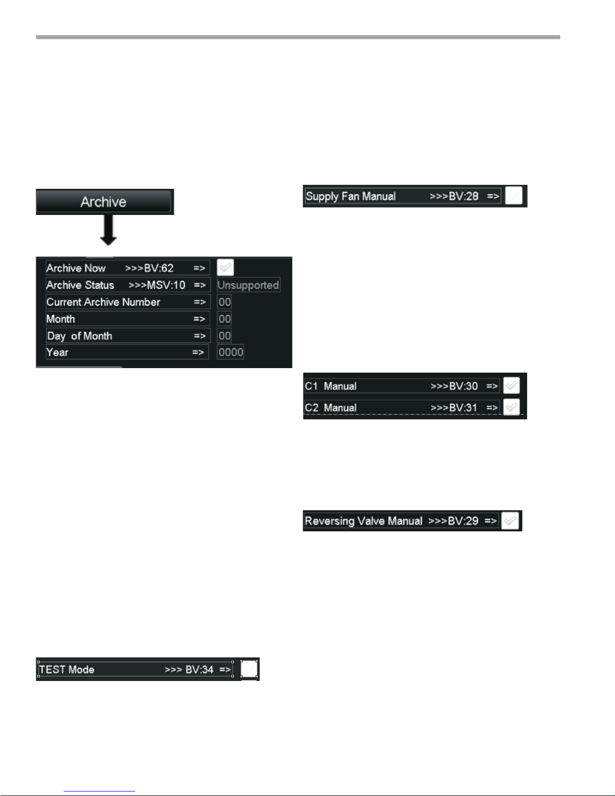
THE SMART SOLUTION FOR ENERGY EFFICIENCY
MPC MultiProtoCol DDC Controls
November 19, 2018
Generating a Field Archive
To archive the current MPC Download, navigate to the
ARCHIVE Screen and click the ARCHIVE NOW checkbox.
Figure 58:
When the Archive Now Box is checked the MPC will
archive the current modied program including all control
settings and display the current archive number, Month,
Day and Year of the Archive will be displayed. See above
information on retrieval procedures.
Test Mode
Test Mode allows the Field personnel to manually
manipulate the following feature for troubleshooting
purposes:
1. Compressor 1
2. Compressor 2
3. Supply Fan
4. Reversing Valve
The Correct Test Sequence is Shown below: Note the
Compressors will not turn on unless the Supply FAN is
ON, so it must be turned on rst.
Figure 59:
1. To Test the Supply FAN, go to the FAN/Filter Control
Screen and check Supply FAN Manual. Check the
Maintenance Screen and ensure the FAN ICON is
present.
2. To test the Compressors, navigate to the
Compressor Setup Screen. Once here you can turn
on and turn off the compressors via the Manual
Compressor Check Boxes. As this is done the ICON’s
on the Maintenance screen will appear and disappear
according to the individual compressors being turned
on and off.
Figure 60:
3. To test the Reversing Valve function, navigate to the
HEAT/COOL Control Screen and check the Reversing
Valve Manual checkbox. You can verify that the RV
Icon appears on the Maintenance screen when the RV
is turned on.
Figure 61:
To enter TEST mode, the user should navigate to the
MODE Settings Screen. Once in this screen. Check the
box for TEST Mode. By navigating to the Maintenance
Screen you should see the Icon for Test Mode and should
see no ICONs for C1, C2, RV, or the FAN Icon.
68

Notes:
THE SMART SOLUTION FOR ENERGY EFFICIENCY
MPC MultiProtoCol DDC Controls
November 19, 2018
69

THE SMART SOLUTION FOR ENERGY EFFICIENCY
MPC MultiProtoCol DDC Controls
November 19, 2018
Notes:
70

Notes:
THE SMART SOLUTION FOR ENERGY EFFICIENCY
MPC MultiProtoCol DDC Controls
November 19, 2018
71

Revision History
Date: Item: Action:
11/19/18 All Added Equipment Touch/, Generation 7
3/7/17 All Misc. Edits
07/14/16 Logo Updated
05/31/16 First Published
*97B0031N01*
97B0031N01
We work continually to improve our products. As a result, the design and specications of each product at the time of order may be changed without
notice and may not be as described herein. Please contact our Customer Service Department at 1-405-745-6000 for specic information on the
current design and specications. Statements and other information contained herein are not express warranties and do not form the basis of any
bargain between the parties, but are merely our opinion or commendation of its products.
7300 S.W. 44th Street
Oklahoma City, OK 73179
Phone: 405-745-6000
Fax: 405-745-605
 Loading...