

ClimateMaster MB Series, MC Series, MD Series, ME Series, MF Series Installation Instructions Manual
...
INSTALLATION INSTRUCTIONS
97B0042N04
Rev.: 04 April, 2014
ENERGY RECOVERY VENTILATOR SERIES MB, MC, MD, ME, MF & MG
Installation Instructions For Energy Recovery Ventilator (Fixed)
For Stand Alone Rooftop Application
Energy recovery COMPONENT certifi ed to the ARI Air-to-
Air Energy Recovery Ventilation Equipment Certifi cation
Program in accordance with ARI Standard 1060-2000.
Actual performance in packaged equipment may vary.
ETL Certifi ed per UL 1995 and CSA 22.2
Inspection
Upon receipt of shipment at the job site, carefully check the
shipment against the bill of lading. Make sure all units have
been received. Inspect the carton or crating housing of each
Rooftop Unit and inspect each unit for damage. Assure that
the carrier makes proper notation of any shortages or damage
on all copies of the freight bill and that he completes a Carrier
Inspection Report. Concealed damage not discovered during
unloading must be reported to the carrier within 15 days of
receipt of shipment. NOTE: It is the responsibility of the
purchaser to fi le all necessary claims with the carrier.
Storage
Upon the arrival of equipment at the job site, immediately store
units in a clean, dry area. Do not stack units. Do not remove
equipment from pallets until equipment is required for
installation.
Unit Protection
Cover rooftop units on the job site. Cap the open ends of pipes.
In areas where painting, plastering, roofi ng, or the spraying of
fi reproof material has not been completed, all due precautions
must be taken to avoid physical damage to the units and
contamination by foreign material. Physical damage and
contamination may prevent proper start-up and may result
in costly equipment cleanup.
Application
Field supplied balancing dampers in duct are recommended.
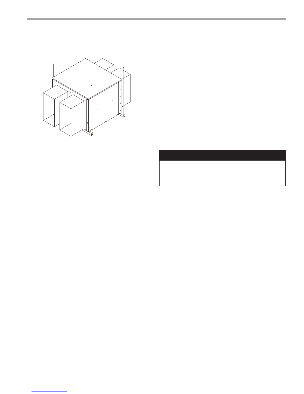
Rigging Unit For Lifting
1. Maximum weight 300-1200 lbs. See Physical Data Table.
2. Remove crating.
3. All panels must be in place for rigging.
4. Remove barometric exhaust hood from door marked fi lter
access. Install barometric exhaust hood over exhaust blower
outlet.
5. Forklift channels must be removed from the base of
ERV.
6. Position unit and provide service access to ERV control
access door and wheel.
7. Duct work should be installed into roof curb before installing
ERV on curb.
8. Roof curb gasket must be applied to all top surfaces of the
curb.
9. Position unit on roof curb and provide service access to ERV
control access door and wheel.
CAUTION!
CAUTION! Danger of sharp metallic edges. Can cause
injury. Take care when servicing unit to avoid accidental
contact with sharp edges.
WARNING!
WARNING! Electric shock hazard. Can cause injury or death.
Before attempting to perform any service or maintenance,
turn the electrical power to unit OFF at disconnect switch(es).
Unit may have multiple power supplies.
Recovery Wheel Mode
The Recovery Wheel mode is accomplished by two blowers
providing continuous exhaust of stale indoor air and
replacement by equal amount of outdoor air. Energy recovery
is achieved by slowly rotating the energy recovery wheel within
the cassette frame work. In winter, the ERV adsorbs heat
and moisture from the exhaust air stream during one half of a
complete rotation and gives them back to the cold, drier intake
air supply during the other half rotation. In summer, the process
is automatically reversed. Heat and moisture are absorbed
from incoming fresh air supply and transferred to the exhaust
air stream. This process allows outdoor air ventilation rates
to be increased by factors of three or more without additional
energy penalty or increase in size of heating or air conditioning
systems.
WARNING!
WARNING! To avoid equipment damage, do not use these
units as a source of heat during the construction process.
The mechanical components and fi lters used in these units
will quickly become clogged with construction dirt and debris
which may cause system damage.
WARNING!
WARNING! The installation of water-source heat pumps and
all associated components, parts, and accessories which
make up the installation shall be in accordance with the
regulations of ALL authorities having jurisdiction and MUST
conform to all applicable codes. It is the responsibility of
the installing contractor to determine and comply with ALL
applicable codes, regulations and ANSI/NFPA No. 70

CLIMATEMASTER WATER-SOURCE HEAT PUMPS
M (ERV) Series
Rev.: 04 April, 2014
This Page Intentionally Left Blank
2
ClimateMaster Water-Source Heat Pumps
THE SMART SOLUTION FOR ENERGY EFFICIENCY
M (ERV) Series
Rev.: 04 April, 2014
9. Connect line voltage power supply to ERV fuse block
in control box of unit from disconnect switch. See
wiring diagram.
10. Ground unit with a suitable ground connection either
through unit supply wiring or an earth ground.
Note: Unit voltage entries must be sealed
weather tight after wiring is complete.
11. Remove motor access panels. Locate belts fastened
to blower assembly. Install belt onto motor and blower
pulley. Adjust motor sheave to correct blower RPM for
CFM and external static pressure requirements. See
charts in this instruction. Multiple pulley arrangements
are available to meet the entire range.
Installation
1. Attach duct work to duct fl anges on roof curb.
2. Set ERV on curb. Verify ERV is positioned on curb
properly.
3. Remove barometric exhaust hood from door marked
fi lter access. Install barometric exhaust hood over
exhaust blower outlet.
4. Remove ERV control access panel to connect fi eld
wiring.
5. Route class II low voltage wire (3 conductor) from
thermostat or energy management through small
bushing in end panel of ERV. See wiring diagram.
a. Thermostat (dependent) - connect in parallel at
rooftop unit with “G”, “C” and “W”. Then connect
matching color at terminal 1, 2, and 3 respectively
on ERV circuit board.
b. Energy Management - provide +24 VAC to “1” and
common, 24 VAC to “2” terminals on ERV circuit
board.
c. Thermostat (dedicated) - splice into +24 vac
(blue wire) at (control circuit board) transformer
connection run wire to “R” terminal. Then run
another wire from “G” terminal to ERV (control
circuit board) terminal block #1.
6. All electrical connections must conform to any local
codes and current National Electric Codes (NEC) and
Canadian Electric Codes (CEC). Refer closely to unit
wiring diagram in unit and/or in these instructions for
proper wiring connections.
7. Refer to the unit nameplate for minimum circuit
ampacity (MCA) and maximum overcurrent protection
size (fuse).
8. Electrical data is listed on unit rating plate and motor
name plates.
CAUTION!
CAUTION! Blower speed must be adjusted for the given
external static pressure and airfl ow (CFM) requirements. If
blower speed is not adjusted for conditions, possible motor
over loading can occur.
12. Replace access panel onto the ERV unit and secure.
13. Restore power to unit.
14. Cleanup once unit is operating properly, caulk
any open joints, holes or seams to make the units
completely air and water tight.
15. Leave this instruction manual with owner or in an
envelope to be kept near unit.
Operation
(How It Works)
The unit contains an Energy Recovery Wheel (ERW)
that is a new concept in rotary air-to-air heat exchangers.
Designed as a packaged unit for ease of installation and
maintenance, only the connection of electrical power is
required to make the system operational.
When slowly rotating through counter fl owing exhaust
and fresh air streams the ERW adsorbs sensible heat
and latent heat from the warmer air stream and transfer
this total energy to the cooler air stream during the
second half of its rotating cycle. Rotating at 50-60
revolutions per minute, the wheel provides constant fl ow
of energy from warmer to cooler air stream. The large
energy transfer surface and laminar fl ow through the
wheel causes this constant fl ow of recovered energy
to represent up to 85% of the difference in total energy
contained within the two air streams.
Sensible and latent heat are the two components of total
climatemaster.com
3
CLIMATEMASTER WATER-SOURCE HEAT PUMPS
M (ERV) Series
Rev.: 04 April, 2014
heat. Sensible heat is energy contained in dry air and
latent heat is the energy contained within the moisture
of the air. The latent heat load from the outdoor fresh air
on an air conditioning system can often be two to three
times that of the sensible heat load and in the winter it is
a signifi cant part of a humidifi cation heat load.
During both the summer and winter, the ERW transfers
moisture entirely in the vapor phase. This eliminates wet
surfaces that retain dust and promote fungal growth as
well as the need for a condensate pan and drain to carry
water.
Because it is constantly rotating when in the air stream,
the ERV is always being cleaned by air, fi rst in one
direction then the other. Because it is always dry, dust or
other particles impinging on the surface during one half
cycle, are readily removed during the next half cycle.
During the heating season, when outdoor air
temperatures are below 10ºF, it is recommended to use
the (optional) low ambient kit (fi eld installed).
Low Ambient Kit is appropriate for climates with limited
HVAC system operation when outdoor temperatures are
below 10ºF.
The frost threshold is the outdoor temperature at which
frost will begin to form on the ERV wheel. For Energy
Recovery Ventilators, the frost threshold is typically below
10ºF. Frost threshold is dependent on indoor temperature
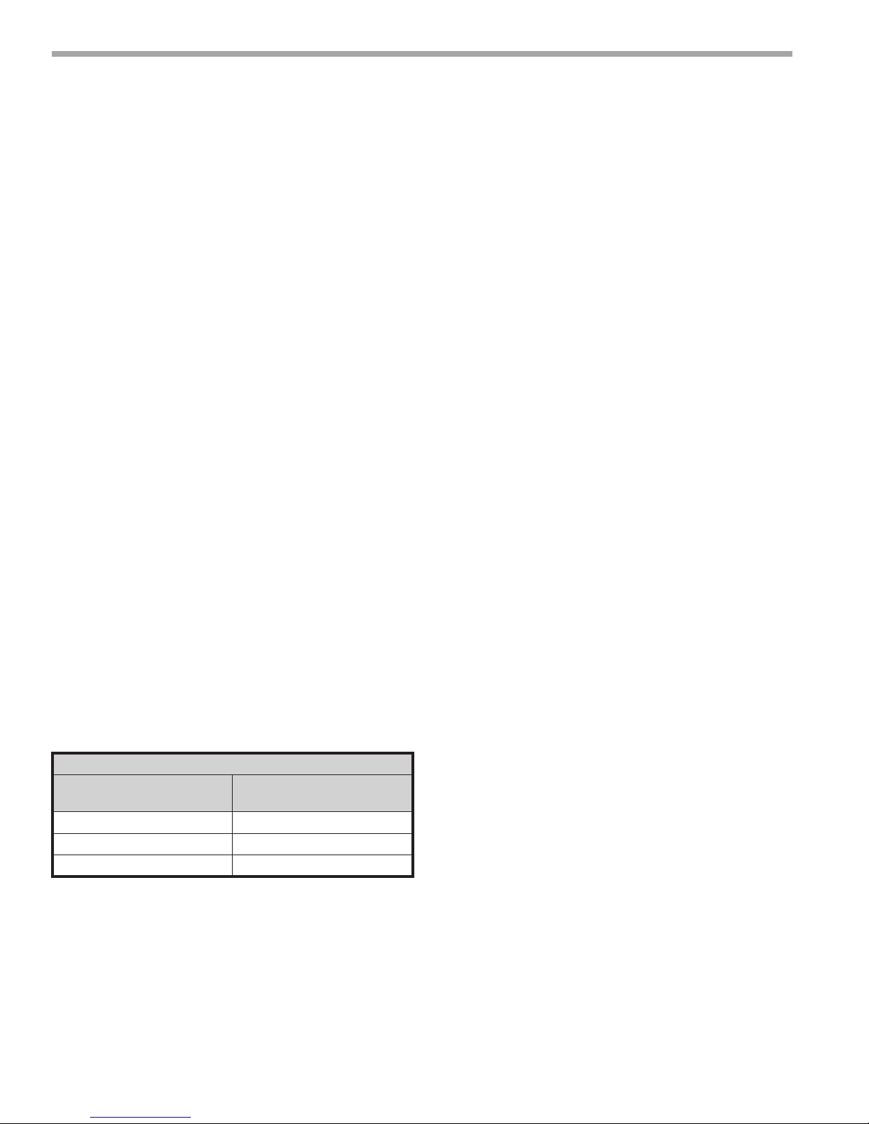
and humidify. The table shows how the frost threshold
temperatures vary depending on indoor conditions.
FROST THRESHOLD TEMPERATURE
INDOOR RH AT 70ºF
FROST THRESHOLD
TEMPERATURE
20% 0ºF
30% 5ºF
40% 10ºF
fan operation is automatically restored when the exhaust
air temperature rises above the thermostat set point.
Provisions for introducing make-up air into the building
when the supply blower is off to avoid depressurization
should be considered.
Recovery Wheel Mode
On a thermostat call for blower operation in heating,
cooling or continuous blower, the ERW will rotate
between fresh air and exhaust air streams. Both the
fresh air and exhaust air blowers will also be operating to
overcome the air resistance of the ERV.
System Check
1. Disconnect main power.
2. Turn to “Cont” for blower operation on thermostat
controlled models.
3. Restore power to unit. Observe ERV wheel rotation
and both fresh air and exhaust air blowers are
operating.
NOTE: If Low ambient kit is used the jumper
between TB37-5 & TB37-6 should be removed.
Also if system check out is being conducted at
low ambient temperatures, technician should
be aware that this kit can cause system not to
operate.
4. Verify that the ERV (3) three phase blower motors
are phased sequentially ensuring correct rotation and
operation.
a. Disconnect power.
b. Reverse any two fi eld power leads to the ERV.
c. Reapply power.
5. Verify that both blower motors are operating under
their full load AMP rating (FLA). The FLA can be
found on each motor and the unit nameplate.
A. Return Damper Settings
Manually adjust position of fi eld installed dampers to
balance air fl ow.
Because Energy Recovery Ventilators have a low frost
threshold, frost control options are not necessary in many
climates. Where outdoor temperatures may drop below
the frost threshold during the ERV operational hours,
exhaust only frost control option is available.
Low Ambient Kit (Optional)
Low Ambient Kit turns off the supply blower when outdoor
temperatures fall below the frost threshold. The exhaust
only thermostat set points are fi eld adjustable. Supply
4
B. Air Flow / Blower Speed Adjustment
Blower speed selection is accomplished by changing
the sheave setting on both fresh air and exhaust air
blowers. To set ERV for the required air fl ow (CFM),
the external static pressure applied to the ERV (duct
static) must be known. See the CFM vs External
Static Pressure chart for the appropriate unit to
determine the correct blower RPM for the specifi ed
CFM and External Static Pressure.
ClimateMaster Water-Source Heat Pumps
THE SMART SOLUTION FOR ENERGY EFFICIENCY
M (ERV) Series
Rev.: 04 April, 2014
After blower speed adjustments have been made. Ensure
that when the belt is replaced it is tensioned correctly.
The motor mounting plate can be adjusted to tension the
belt. If using a belt tension checker, adjust the span to the
appropriate setting and check the belt defection force.
The belt defl ection force should be between 5-8 lbs or the
lowest tension at which the belt will not slip under peak
load conditions.
1. Disconnect main power to unit before making
adjustment to economizer and/or ERV unit.
2. Replace ERV control access cover.
3. Set thermostat to normal operating position.
4. Restore power to unit.
Maintenance
1. All motors use pre-lubricated sealed bearings; no
further lubrication is necessary.
2. Make visual inspection of motors, belts and wheel
rotating bearings during routine maintenance.
3. Eight pie-shaped segments, are seated on stops
between the segment retainer which pivots on the
wheel rim and secured to the hub and rim of wheel.
Annual inspection of the self cleaning wheel is
recommended. With power disconnected, remove
ERV access panels (rear) and unplug [J150 & P150]
(Refer to wiring diagram in this instruction
manual). Remove segment and wash with water and/
or mild detergent.
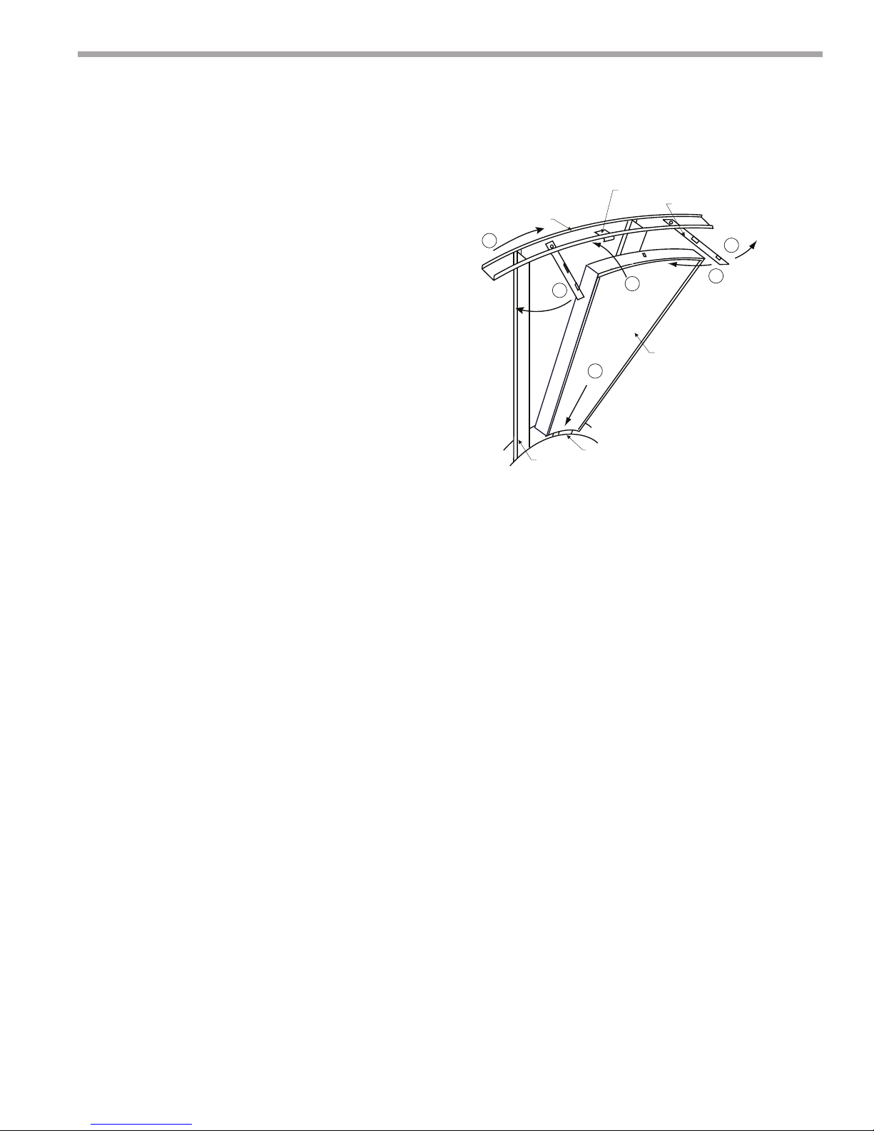
4. To install wheel segments follow steps A through
E . See Figure 1. Reverse procedure for segment
removal.
A. Unlock two segment retainers (one on each side of
the selected segment opening.
B. With the embedded stiffener facing the motor side,
insert the nose of the segment between the hub
plates.
C. Holding segment by the two outer corners, press
the segment towards the center of the wheel
and inwards against the spoke fl anges. If hand
pressure does not fully seat the segment, insert
the fl at tip of a screw driver between the wheel
rim and outer corners of the segment and apply
downward force while guiding the segment into
place.
D. Close and latch each segment retainer under
segment retaining catch.
E. Slowly rotate the wheel 180º. Install the second
segment opposite the fi rst for counterbalance.
Rotate the two installed segments 90º to balance
the wheel while the third segment is installed.
Figure 1
WHEEL RIM
E
D
SPOKE
SEGMENT RETAINER CATCH
SEGMENT RETAINER
C
SEGMENT
B
HUB
A
D
Rotate the wheel 180º again to install the fourth
segment opposite the third. Repeat this sequence
with the remaining four segments.
Pulley Kit Installation
The units are shipped from the factory at the low static
setting. Pulley kits are available for the medium and high
static settings. To install a pulley kit.
1. Check content of pulley kit, if pulley kit contains:
a. An adjustable sheave and a fi xed pitch pulley then
remove belt and both motor and blower pulley
b. An adjustable sheave then remove the motor
pulley.
c. A fi xed pitch pulley then remove the blower pulley.
2. Replace pulley(s) with the pulley(s) from pulley kit.
Make sure each pulley is installed with a key. Tighten
the set screw on the pulley(s) to 100 in.lb.
3. Install the belt that came with the pulley kit. Tension
belt as explained in the blower speed adjustment
section.
4. Check the speed of the blower. Adjust the motor
sheave to increase or decrease the speed of the
blower. See blower adjustment section.
climatemaster.com
5
 Loading...