

Page 1

C
LIMATE
M
ASTER
¤
Flow Controller
GEOTHERMAL PUMPING MODULE
INSTALLED BY:
Flow Controller
Installation, Operation, &
Maintenance Instructions
12/98
TABLE OF CONTENTS
Flow Controller Description 2
Flow Controller Mounting 2
Piping Installation 3
Electrical Wiring 4
Flushing the Earth Loop 5
Antifreeze Selection 6
Antifreeze Charging 7
Heat Pump Freezestat Setting 8
Pressure Drop Tables 9
Earth Loop Pressurization 9
Flow Controller Start-Up 10
Pump Cartridge Replacement 10
Closed Loop Design 11
Polyethylene Pressure Drop 14
Rubber Hose Pressure Drop 15
Closed Loop Installation 16
Building Entry 18
1
Page 2
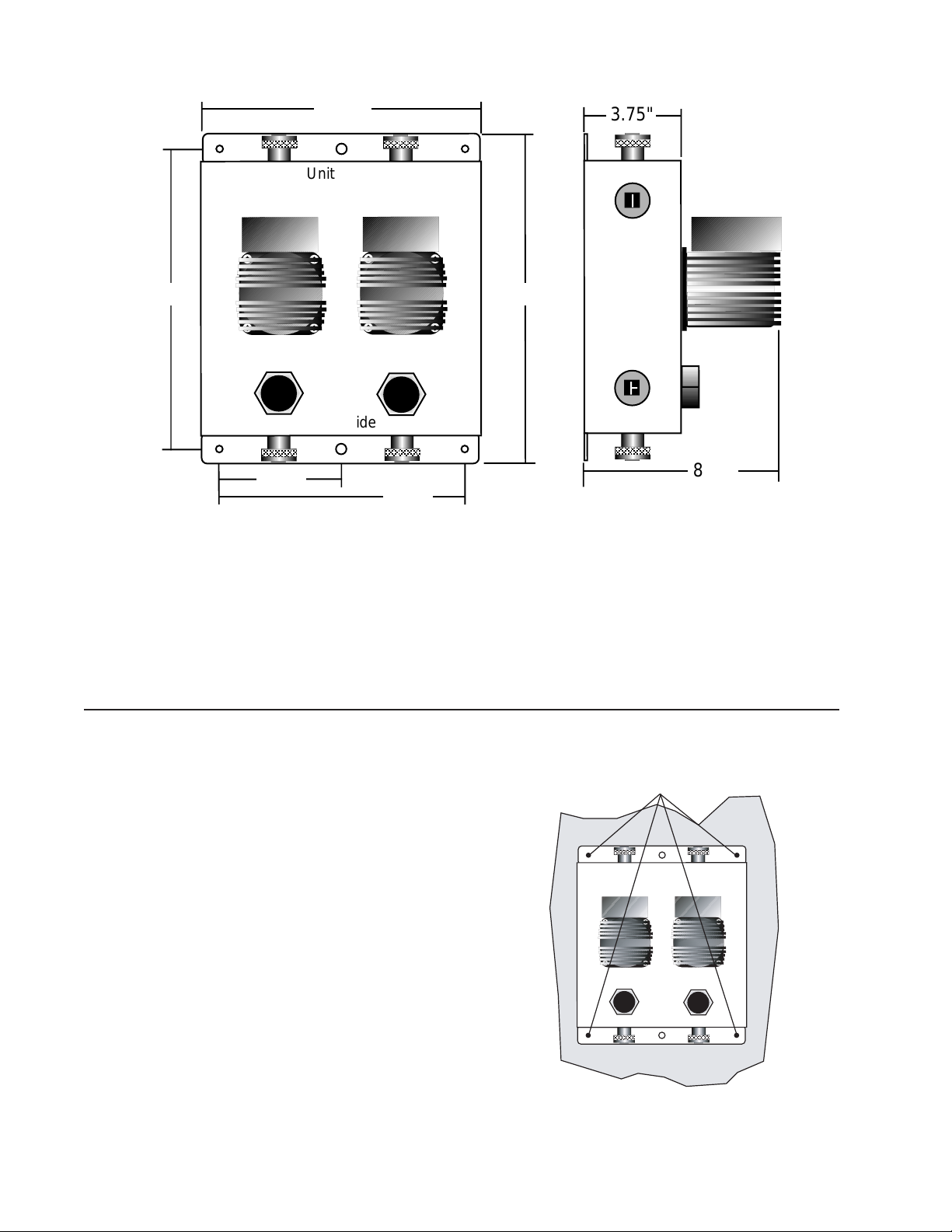
FLOW CONTROLLER DESCRIPTION
10.75"
Unit Side
13.75"
TTaacco
o
TTaacco
o
Loop Side
4.38"
8.75"
Figure 1 - Flow Controller Dimensions
The AFCS1A and 2A are insulated flow controllers
containing all flush, fill, and isolation connections for a
residential and light commercial geothermal closed loop
system that require a flow rate of no more than 20 gpm.
The AFCS1A and 2A are equipped with a large bore 1 1/
4" FPT swivel fittings for both earth loop and heat pump
unit connections. Either 1 (AFCS1A) or 2 (AFCS2A)
Taco 0013 chilled water rated cartridge type circulators
3.75"
15.00"
8.50"
are included with the flow controller. Included in this kit
are:
• 2 Lag bolts for mounting AFC onto stud walls
• 4 Self-drilling sheet metal screws for mounting AFC
onto heat pump
• 2 1" MPT PVC plug for sealing flush ports after
installation
FLOW CONTROLLER MOUNTING
General
The installation of the ClimateMaster Flow Controller
shall be made in accordance with all applicable codes.
Mounting the Flow Controller
The flow controller should be located as close to the unit
as possible to limit the length of the rubber hose kit and
thus its associated pressure drop. In general the flow
controller can be mounted in any orientation with the
exception of when the pump shafts are in a vertical
position as when it is laid flat on the floor or any similar
position. The controller is typically mounted in one of
three locations. Be certain there is adequate access to all
required flush ports and valves before mounting.
Stud Wall - Mounting on stud wall with or without
drywall can be accomplished by using the two supplied
lag bolts through the top and bottom center holes directly
into the studs as shown in Figure 2.
Self-drilling screws into sheet metal 4 places.
DO NOT PUNCTURE INTERNAL
COMPONENTS!
Unit Side
o
TTaacco
Loop Side
Heat Pump Cabinet
TTaacco
o
Figure 2 - Mounting Flow Controller on Stud Wall
2
Page 3

Side of Unit - Mounting on the side of the unit can be
accomplished by using the four self-drilling screws
directly into the sheet metal access panels or cabinet as
shown in Figure 3. Be careful not to puncture any
internal piping or other components with the screws. It
should be remembered that heat pump access will be
limited in this mounting position.
Tubing Insulation
brought up to cover
complete connection
1-1/4”
MPT
Remove
Cover
TTaacco
Unit Side
o
Loop Side
Figure 4 - AFCS1 Piping Detail
Figure 3 - Mounting Flow Controller on Side of Unit
Concrete wall - Mounting onto a concrete wall can be
accomplished by using 4 1/4" ‘Tapcon’ screws (supplied
by others) directly into the concrete wall.
Piping Installation
The Flow controller features 1 1/4" FPT swivel fittings
for flexible and easy installation. Table 1 illustrates the
connection options available for the AFCS1A and 2A.
Avoid using 3/4" piping on flows greater than 6 gpm.
Pressure drop in piping systems should be calculated to
insure adequate flow through the unit. All piping should
be insulated with closed cell insulation of 1/2" wall
thickness. Table 2 shows the insulation requirements for
typical piping materials. Piping insulation should be
glued and sealed to prevent condensation using closed
cell insulation glue. The swivel connectors on the flow
controller are designed to be hand tightened only.
Table 2 - Typical Piping Insulation Materials
Piping Material Insul Description
1" Hose Kit 1-3/8" ID - 1/2" wall
1" IPS PE 1-1/4" ID - 1/2" wall
1-1/4" IPS PE 1-5/8" ID - 1/2" wall
2" IPS PE 2-3/8" ID - 1/2" wall
Loop side piping is typically polyethylene piping
directly into the flow controller. Connection to the flow
controller can be accomplished by a fusion-to-brass MPT
adapter (GFMA66). In multiple flow controller systems
such as multifamily housing, PVC can also be used on
the loop side, remembering however that the transition
from PVC to PE should be accomplished by a flange
connection and PVC is approved for use only as an
indoor piping material in earth loops.
Unit side piping is typically connected using the
ClimateMaster hose kit (AHK5E) which contains all
fittings necessary for connection between the flow
controller and the unit as shown in Figure 5. In the
AFCS1A remove cover and make connections as shown
in Figure 4, remembering all areas of the piping should
be insulated to prevent condensation.
In multiple unit systems, PVC adapters (1 1/4" MPT x
PVC socket) to the flow controller and standard PVC
piping materials can be used to ‘tee’ more than one unit
into the flow controller. It is recommended that a hose kit
still be used at the end of the PVC piping run to facilitate
ease of installation and service of the units as shown in
Figure 6. Insulate all exposed piping. Plastic-to-metal
threads should not be used due to their leakage potential.
To Heat Pump 1"
Swivel Fitting
P/T Port
Rubber Hose Max of
15" Each Side
To Flow Controller 1 1/4"
Swivel Fitting
All Stainless
Hose Clamp
Figure 5 - AHK5E Hose Kit Typical Detail
Table 1 - AFCS1A and 2A Connection Materials
To Fittings
PVC 1-1/4" MPT x 1" PVC Glue Socket
PE Fusion 1-1/4" MPT x 1-1/4" PE Fusion
PE Barb 1-1/4" MPT x 1-1/4" insert barb*
Copper Sweat 1-1/4" MPT x 1" sweat**
Copper Thread 1-1/4" MPT x 1" MPT Nipple
* Use double all-stainless hose clamps
** Sweat before connecting to flow controller
From Flow Controller
1 1/4" MPT x Glue Socket
15" each side
1 or 1 1/2"
SCH 40 PVC
Insert Barb x Glue Socket
Rubber Hose Max of
15" each side
To Heat Pump #1 To Heat Pump #2
Rubber Hose Max of
Figure 6 - Two Units Utilizing One Flow Controller
(one side shown)
3
Page 4
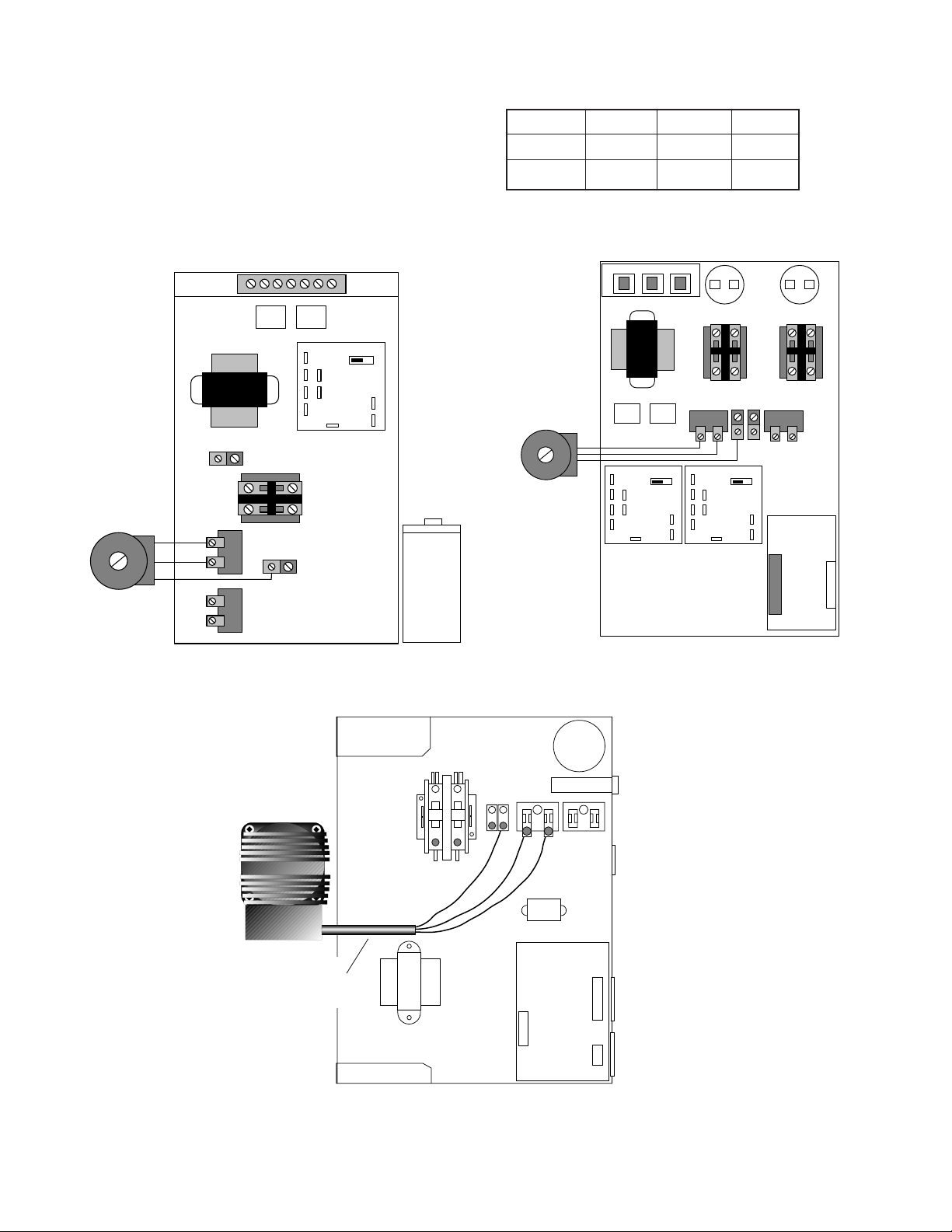
FLOW CONTROLLER ELECTRICAL WIRING
Power wiring to the flow controller should conform to all
applicable codes. Figure 7 illustrates the wiring required
for the Classic and Figure 8a and 8b for Genesis. Note
the flow controller is available in only in 230V single
phase voltage. Pumps are fused through a pair of circuit
breakers in the unit control boxes. See electrical table for
flow controller characteristics.
External Loop Pump(s)
208/230 Volt-4 Amp Max.
Transformer
L2 L1
CRR
Unit Ground
Loop Pump
Term Blk
HWG Pump
Term Blk
PR
CCM PCB
T1
HPS
LPS
Y
X
Compressor
Contactor
Pump Ground
Min Sec.
T
C
Electrical Table
Model Volts Amps HP
AFCS1A 230 .88 1/8
AFCS2A 230 1.76 1/4
Circuit Breakers
Transformer
External Loop Pump(s)
208/230 Volt-4 Amp Max.
CRR
T1
Y
CCM PCB
HPS
LPS
X
PR
Min Sec.
T
C
Compressor
Contactor
L2 L1
Loop Pump
Term Blk
T1
HPS
LPS
Y
X
Ground
CCM PCB
Min Sec.
T
C
Thermostat
Connection
Compressor
Contactor
HWG Pump
Term Blk
ICM2 Controller
Figure 7 - Power Wiring to Classic Series
o
TTaacco
External Pump
Power Supply
See electrical table for
wire and breaker size
Figure 8B - Power Wiring to Genesis Series
Contactor -CC
Transformer
Figure 8A - Power Wiring to Ultra Classic Series
Capacitor
Circ Brkr
HWG PB2
Loop PB1
T2
Grnd
L1
L2
BR
CXM Control
CB
Low Voltage
Connector
T1
T1
T2
4
Page 5
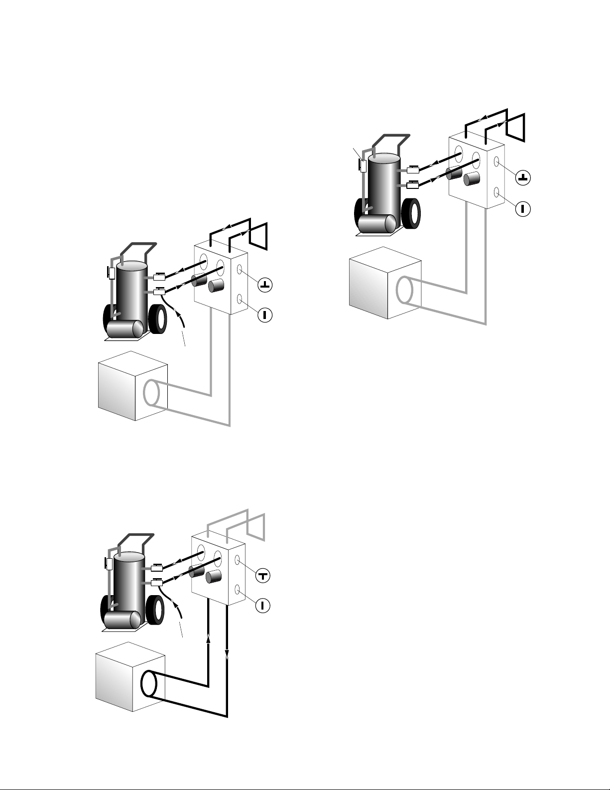
FLUSHING THE EARTH LOOP
Once piping is completed between the unit, flow controller, and the ground loop, final purging and charging of
the loop is needed.
A flush cart (at least a 1.5 hp pump) is needed to achieve
adequate flow velocity in the loop, to purge air and dirt
particles from the loop itself. Antifreeze solution is used
in most areas to prevent freezing. All air and debris must
be removed from the earth loop piping system before
operation. Flush the loop with a high volume of water at
a high velocity (2 fps in all piping) both directions, using
a filter in the loop return line of the flush cart to eliminate debris from the loop system. The steps below must
be followed for proper flushing.
Loop
Flush Cart
Flow
Controller
Valve
Positions
Garden Hose
Unit
Figure 9A - Valve Position A - Loop Fill
Fill loop with water from a garden hose through flush
cart before using flush cart pump to ensure an even fill
and increase flushing speed. When water consistently
returns back to the flush reservoir switch to valve
position B.
Flush Cart
Loop
Flow
Controller
Valve
Positions
This position should be switched while filling, to fill the
unit heat exchanger and hose kit. This should be maintained until water consistently is returned into the flush
reservoir.
Loop
Dead Head
Pump Test
for Air
Unit
Flush Cart
Flow
Controller
Valve
Positions
Figure 9C - Valve Position C- Loop Flush
Switch to valve position C. The supply water may be
shut off and the flush cart turned on to begin flushing.
Once the flush reservoir is full, do not allow the water
level in the flush cart tank to drop below the pump inlet
line or air can be pumped back out to the earth loop. Try
to maintain a fluid level in the tank above the return tee
so that air cannot be continuously mixed back into the
fluid. 50 psi surges can be used to help purge air pockets
by simply shutting off the return valve going into the
flush cart reservoir. This ‘dead heads’ the pump to 50 psi.
To dead head the pump until maximum pumping pressure is reached, open the valve back up and a pressure
surge will be sent through the loop to help purge air
pockets from the piping system. Notice the drop in fluid
level in the flush cart tank. If all air is purged from the
system, the level will drop only 1-2" in a 10" diameter
PVC flush tank (about a half gallon) since liquids are
incompressible. If the level drops more than this,
flushing should continue since air is still being compressed in the loop fluid. Do this a number of times.
When the fluid level is dropping less than 1-2" in a 10"
diameter tank the flow can be reversed.
Garden Hose
Unit
Figure 9B - Valve Position B - Unit Fill
5
Page 6
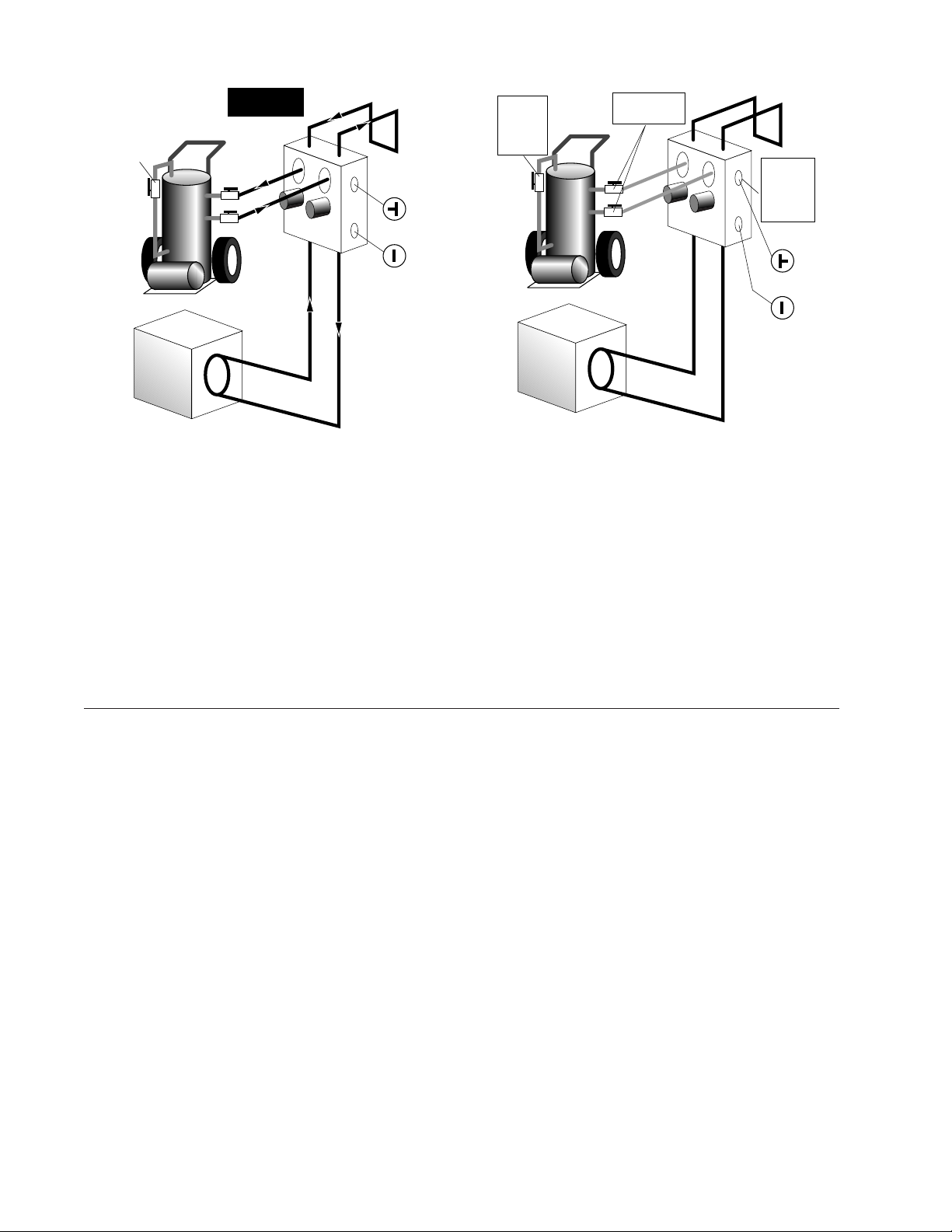
Dead Head
Pump Test
for Air
Flush Cart
Add Antifreeze
Now if Needed
Loop
Flow
Controller
Valve
Positions
1
Dead Head
Pump to
Pressurize
to 50 PSI
Flush Cart
2
Close to Isolate
Flow Controller
Loop
3
Close Flow
Controller
Valves for
Operation
Mode
Valve
Positions
Unit
Figure 9D - Valve Position D - Full Flush
Now by switching both valves to this position water will
flow both through the loop and the unit heat exchanger.
Finally the "dead head" test should be checked again for
an indication of air in the loop. This fluid level drop is
your only indication of air in the loop. Antifreeze may
be added during this part of the flushing procedure
(see antifreeze section for details).
Close the flush cart return valve, and after pressurizing,
close the flush cart supply valve to pressurize the loop to
a static pressure of at least 50 psi. If water pressure is
ANTIFREEZE SELECTION
General
In areas where minimum entering loop temperatures drop
below 40°F or where piping will be routed through areas
subject to freezing, antifreeze is needed. Alcohols and
glycols are commonly used as antifreezes, however your
local representative should be consulted for the antifreeze
best suited to your area. Freeze protection should be
maintained to 15°F below the lowest expected entering
loop temperature. For example, if 30°F is the minimum
expected entering loop temperature, the leaving loop
temperature would be 25-22°F and freeze protection
should be at 15°F (30°F-15°F=15°F). All alcohols should
be premixed and pumped from a reservoir outside of the
building when possible or introduced under water level to
prevent fuming. Initially calculate the total volume of
fluid in the piping system using Table 3. Then use the
percentage by volume shown in Table 4 for the amount
of antifreeze. Antifreeze concentration should be checked
from a well mixed sample using a hydrometer to measure
specific gravity.
Unit
Figure 9E - Valve Position E - Pressurize and Operation
low, use an air compressor to bump the pressure up
through the P/T port. The loop may be isolated by
moving to valve position E keeping watch on the
pressure gauge of the flush cart for pressure greater than
50 psi. Loop static pressure will fluctuate with the
seasons and pressures will be higher in the winter months
than during the cooling season. This fluctuation is normal
and should be considered when charging the system
initially. Unhook flush cart from the flow controller.
Install counter sink plugs using sealant compatible with
PVC.
Antifreeze Characteristics
Selection of the antifreeze solution for ClimateMaster
closed loop earth coupled systems requires the consideration of many important factors which have long-term
implications on the performance and life of the equipment. Each area of concern leads to a different “best
choice” of antifreeze. The fact is that there is no “ideal”
antifreeze and any choice will require compromises in
one area or another. Some of the factors to consider are
safety, thermal performance, corrosiveness, local codes,
stability, convenience, and cost.
Methanol - Methanol or wood alcohol is considered
toxic in any form, good heat transfer, low to mid price,
flammable in concentrations greater than 25%, noncorrosive, and low viscosity. Methanol has delivered
outstanding performance in earth loops for over 10 years.
Its only drawbacks are toxicity and flammability.
Although methanol enjoys widespread consumer use as a
windshield washer fluid in even higher concentrations,
6
Page 7

some local codes may limit its use in earth loops. To
increase safety, a premixed form should be used on the
job site to increase the safety factor. Pure methanol can
be purchased from any chemical supplier.
Ethanol - Ethanol or grain alcohol exhibits good heat
transfer (slightly less than methanol), higher price, and is
flammable in concentrations greater than 10%. Ethanol is
generally non-corrosive and has medium viscosity.
Ethanol in its pure form is considered non toxic and
shows promise as a geothermal heat transfer fluid,
however, the U.S. Bureau of Alcohol, Tobacco, and
Firearms (ATF) limit its distribution. All non-beverage
ethanol is required to be denatured and rendered unfit to
drink. Generally this is done by adding a small percentage of toxic substances such as methanol, benzene, or
gasoline as a denaturant. Many of these denaturants are
difficult to identify by the casual user and many are not
compatible with polyethylene pipe. Only denatured
ethanol can be purchased for commercial use. CM does
not recommend the use of ethanol because of the unknown denaturants included and their possible toxicity
and damage resulting to polyethylene piping systems.
Ethylene glycol - Generally non-corrosive, expensive,
medium heat transfer, however is considered toxic. Its
toxicity has prevented its widespread use in the ground
source industry in spite of its widespread use in traditional watersource heat pump applications. CM does not
currently recommend ethylene glycol as a ground source
antifreeze.
Propylene glycol - Non toxic, non-corrosive, expensive,
hard to handle when cold, poorest heat transfer, has
formed “slime-type” coatings inside pipe. Poor heat
transfer has required its removal in some systems.
Propylene glycol (PG) is acceptable in systems anticipating loops temperatures no colder than 40°F. These
systems typically are antifreeze because of ambient
conditions (outside plumbing or cooling tower, etc.).
When loop temperatures are below 40°F., the fluid
becomes very difficult to pump, and heat transfer
characteristics suffer greatly. CM recommends only food
grade propylene glycol be used to prevent the corrosion
inhibitors (often present in other mixtures) from reacting
with local water and "coming" out of solution to form
slime type coatings inside heat exchangers and thus
hinder heat transfer.
GS4 (Potassium acetate) - Non toxic, good heat
transfer, high price, non-corrosive with added inhibitors,
low viscosity. Due to its low surface tension, GS4 has
been known to leak through mechanical fittings and
certain thread sealants. A variant of the salt family, it can
be extremely corrosive when exposed to air. CM does not
recommend the use of GS4 with its products due to the
leaking and ultimate corrosion problems associated with
it.
Contact the ClimateMaster Technical Services Department if you have any questions as to antifreeze selection.
ANTIFREEZE CHARGING
It his highly recommended to utilize premixed
antifreeze fluid where possible to alleviate many
installation problems and extra labor.
The following procedure is based upon pure methanol
and can be implemented during the Full Flush
procedure with three-way valves in the Figure 9D Valve Position D. If a premixed methanol of 15°F
freeze protection is used, the system can be filled and
flushed with the premix directly to prevent handling
pure methanol during the installation.
1) Flush loop until all air has been purged from system
and pressurize to check for leaks before adding any
antifreeze.
2) Run discharge line to a drain and hook up antifreeze
drum to suction side of pump (if not adding below
water level through approved container). Drain flush
reservoir down to pump suction inlet so reservoir can
accept the volume of antifreeze to be added.
3) Calculate the amount of antifreeze required by first
calculating the total fluid volume of the loop from
Table 3. Then use Table 4 for the appropriate freeze
protection level. Many southern applications require
freeze protection because of exposed piping and
flow controller ambient conditions. An extra 10°F
of freeze protection is needed in Paradigm outdoor
applications.
Table 3 - Fluid Volume of Common Piping Materials
Fluid Volume (gal/100' pipe)
Pipe Size Volume
1" 4.1
Copper 1.25" 6.4
1.5" 9.2
Rubber Hose 1" 3.9
Polyethylene 3/4" IPS SDR11 2.8
1" IPS SDR11 4.5
1 1/4" IPS SDR11 8.0
1 1/2" IPS SDR11 10.9
2" IPS SDR11 18.0
1 1/4" IPS SCH40 8.3
1 1/2" IPS SCH40 10.9
2" IPS SCH40 17.0
Unit Heat Exchanger Typical 1.0
Flush cart tank 10" diam x 3 ft 10.0
7
Page 8
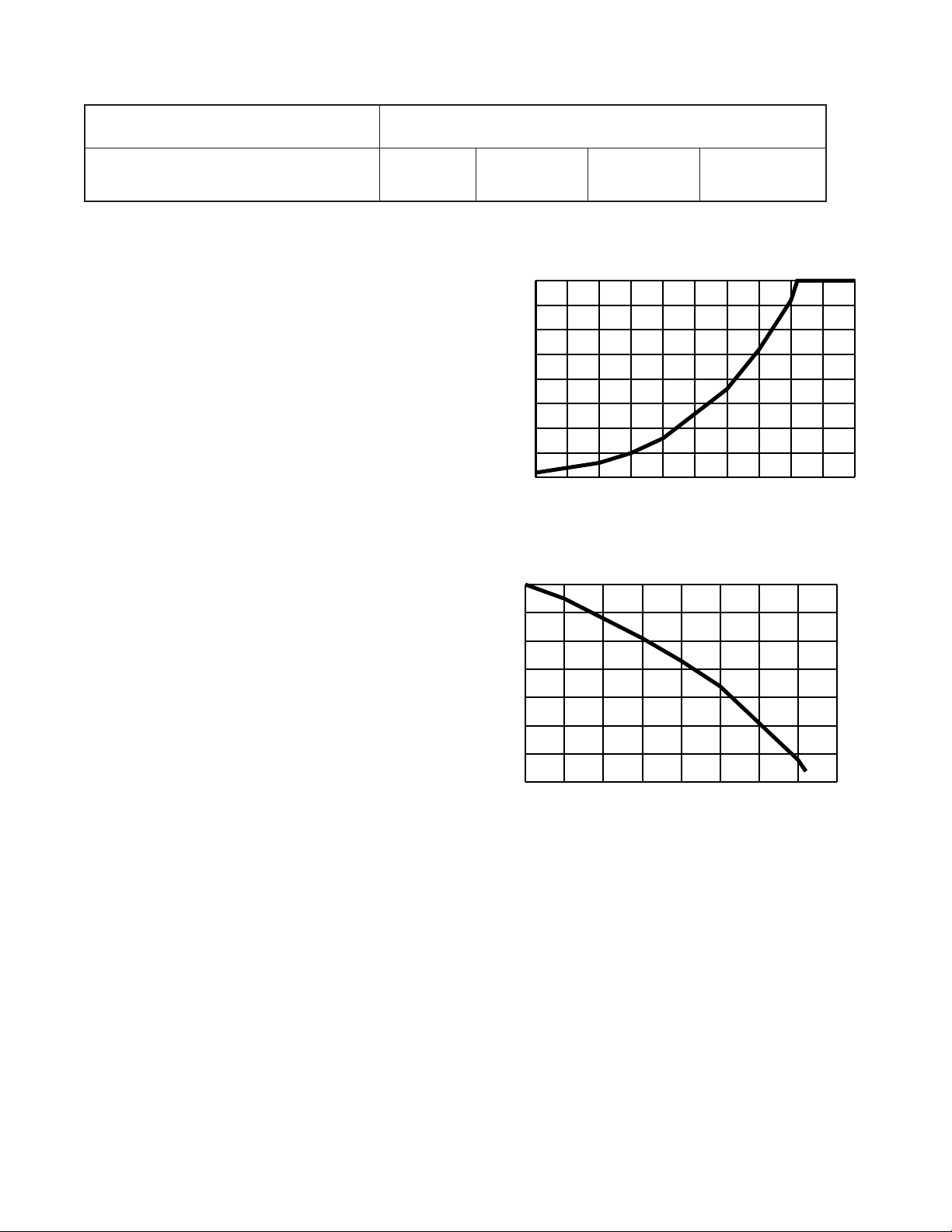
Table 4 - Antifreeze Percentages by Volume
-50 -40 -30 -20 -10 0 10 20 30 40 50
0.960
0.965
0.970
0.975
0.980
0.985
0.990
0.995
1.000
Freeze Protection - Degrees F˚
Specific Gravity
Type Minimum Temperature for Freeze Protection
10°F15°F20°F25°F
Methanol 25% 21% 16% 10%
100% USP food grade Propylene Glycol 38% 30% 22% 15%
4) Isolate unit and prepare to flush only through loop.
Start flush cart, and gradually introduce the required
amount of liquid to the flush cart tank (always
introduce alcohols under water or use suction of
pump to draw in directly to prevent fuming) until
attaining the proper antifreeze protection. Noting the
rise in flush reservoir level indicates amount of
antifreeze added. Some carts are marked with
measurements in gallons. A ten inch diameter, three
foot cylinder holds approximately eight gallons of
fluid. If more than one tankful is required, the tank
should be drained immediately by opening the waste
valve of the flush cart, noting the color of the
discharge fluid. Adding food coloring to the antifreeze can help indicate where the antifreeze is in the
circuit, which prevents the dumping of antifreeze out
the waste port. Repeat if necessary.
5) Be careful when handling methanol. The fumes are
flammable, and care should be taken with all
flammable liquids, such as alcohols. Open flush
valves to flush through both the unit and the loop;
flush until fluid is homogenous and mixed. It is
recommended to run the unit in the heating and
cooling mode for 15-20 minutes each to ‘temper’
the fluid temperature and prepare it for pressurization. Devoting this time to clean up can be
useful. This procedure helps prevent the periodic
“flat” loop condition.
6) Close the flush cart return valve; and immediately
thereafter, close the flush cart supply valve, leaving a
positive pressure in the loop of approximately 50psi.
This is a good time to pressure check the system as
well. Check the freeze protection of the fluid with
the proper hydrometer to ensure that the correct
amount of antifreeze has been added to the system.
The hydrometer can be dropped into the flush
reservoir and the reading compared to Figure 1A for
Methanol and 1B for Propylene Glycol to indicate
the level of freeze protection. Do not antifreeze more
8
than a +5°F freeze point. Specific gravity hydrometers are available from ClimateMaster. Repeat after
reopening and flushing for a minute to ensure good
second sample of fluid. Inadequate antifreeze
protection can cause nuisance freezestat lockouts
during cold weather.
Note: Always dilute alcohols with water (at least 50%
solution) before using (when possible).
Chart 1A - Methanol Specific Gravity
Chart 1B - Propylene Glycol Specific Gravity
1.07
1.06
1.05
1.04
1.03
1.02
Specific Gravity
1.01
1.00
-40 -30 -20 -10 0 10 20 30 40
Freeze Protection - Degrees F˚
7) Close the flush cart return valve; immediately
thereafter, close the flush cart supply valve, shut off
the flush cart leaving a positive pressure in the loop
of approximately 40-50 psi for summer and 50-75
psi for winter. Refer to Figure 9E for more details.
Heat Pump Freezestat Setting
When an antifreeze is used, the freezestat wires should be
switched to activate the low temperature freezestat
switch to avoid nuisance faults or lockouts. See the unit
installation manual for further details on switching
freezestat settings.
Page 9

Pressure/Temperature Ports
The pressure/temperature ports (P/T ports) supplied with
the earth loop connector kit are provided as a means of
measuring flow and temperature. The water flow (GPM)
through the unit can be checked by measuring the
incoming water pressure at the supply water P/T port
and subtracting the leaving water pressure at the return
water P/T port. Comparing the pressure differential to
the pressure drop/flow (Table 5) will determine the flow
rate through the unit. For reference, every 1 psi equals
2.31 feet of head, if conversion is needed.
ClimateMaster units require 2.25-3 gpm per nominal
cooling ton when installed in conjunction with an earth
loop. Note: Minimum flow for units is 2.25 gpm
per ton.
Example: A VP036 with a 3.8 PSI pressure drop would
be equivalent to 9 GPM on the chart. More flow will not
hurt the performance. However, insufficient flow can
significantly reduce capacity and possibly even cause
damage to the heat pump in extreme conditions. Digital
thermometers and pressure gauges needed for the P/T
ports are available from ClimateMaster.
Note: Pressure/temperature gauges should be pushed
gently into P/T ports to prevent internal damage to the
port.
Table 5 - Classic, Ultra Classic, and Paradigm Pressure Drop
Earth Loop Pressure
The earth loop must have a slight positive pressure to
operate the pumps (>3 psi). The system pressure will
drop as the plastic earth loop pipe relaxes and will
fluctuate as the fluid temperature changes. Typical earth
loop pressures range from approximately 15-50 psi. At
the start-up of a system, you should leave the earth loops
with a (static) holding pressure of approximately 40-50
psi summer or 50-75 psi winter. Maximum operating
pressure should never exceed 100 psi under any
circumstance. It is recommended to run the unit in
the heating and cooling mode for 15-20 minutes each
to ‘temper’ the fluid temperature and prepare it for
pressurization. This procedure helps prevent the
periodic “flat” loop condition.
9
Page 10

FLOW CONTROLLER INITIAL START-UP
After pressurization, be sure to insure the loop flow
controller provides adequate flow through the unit by
checking pressure drop across the heat exchanger and
comparing it to the figures shown in Table 5. Flow
70
65
60
55
50
45
40
35
30
25
20
15
10
Total Head (ft. of hd.)
5
0
AFCS2A
AFCS1A
controller pump performance is shown in Chart 2.
Chart 2 - Flow Controller Performance
Start-Up of Flow Controller
1) Check to make sure that the loop and unit isolation
valves are completely open and the flush ports are
closed and sealed.
2) Check and record the earth loop pressure via the P/T
ports. Loop Pressure = In Out
3) Check and record the flow rate.
Flow Rate = gpm
4) Check performance of unit. Refer to unit installation
manual. Replace all caps to prevent pressure loss.
35302520151050
Flow Rate (gpm)
PUMP CARTRIDGE REPLACEMENT PROCEDURE
First isolate the pump in question as in Figure 10. Always
disable power to the pumps and remove pump power
wiring if needed. Close valves as in Step 1 of Figure 10.
Flow
Controller
Return Valve
Supply Valve
Bucket/Drain
Garden Hose Supply
Unit
Figure 10 - Cartridge Replacement Procedure
Loop
1
Close to isolate
pump tor
Cartridge change
2
Open to flush unit
with garden hose
and then pressurize
Valve
Positions
• Remove two allen head mounting bolts and lift off
pump stator housing. Lay out rags to soak up loop
fluid.
• Remove remaining two allen head mounting bolts and
remove cartridge, noting the large ‘o’-ring seal. Loop
fluid could spill from system.
• Replace with new cartridge, insuring the ‘o’-ring is in
place and install the two allen head mounting bolts.
• Reinstall the stator housing using the remaining allen
head mounting bolts.
• Place garden hose supply and return on flush ports as
shown in Figure 10 and open valves to flush through
the unit portion of loop. When water flows clear, close
return side to pressurize; finally, close the supply side
valve. Close 3-way valves to operation position Figure
9E. The loop can also be reflushed, using the complete procedure outlined for installation.
Remember, this procedure will dilute the antifreeze
mixture by a few gallons. If performed more than twice
on any earth loop, the antifreeze concentration should
be checked with a hydrometer and antifreeze added as
needed.
10
Page 11

GEOTHERMAL CLOSED LOOP DESIGN
Closed Loop Basics
Closed Loop Earth Coupled Heat Pump systems are
commonly installed in one of three configurations:
horizontal, vertical, and pond loop. Each configuration
provides the benefit of using the moderate temperatures
of the earth as a heat source/heat sink. Piping configurations can be either series or parallel.
Series piping configurations typically use 1-1/4 inch, 1-1/
2 inch, or 2 inch pipe. Parallel piping configurations
typically use 3/4 inch or 1 inch pipe for loops and 1-1/4
inch, 1-1/2 inch, or 2 inch pipe for headers and service
lines. Parallel configurations require headers to be either
“closed-coupled” short headers or reverse return design.
Select the installation configuration which provides the
most cost effective method of installation after considering all application constraints.
Loop design takes into account two basic factors. The
first is accurately engineered system to function properly
with low pumping requirement and adequate heat transfer
to handle the load of the structure. The second is to
design a loop with the lowest installed cost while still
maintaining a high level of quality. These factors have
been taken into account in all of the loop designs
presented in this manual.
In general terms, all loop lengths have been sized by the
ClimateMaster loop sizing software so that every loop
has approximately the same operating costs. In other
words, at the end of the year the home owner would have
paid approximately the same amount of money for
heating, cooling, and hot water, no matter which loop
type was installed. This leaves the installed cost of the
loop as the main factor for determining the system
payback. Therefore, this analysis says "install the most
economical system possible given the installation
requirements".
Pipe Fusion Methods
Two basic types of pipe joining methods are available for
earth coupled applications. Polyethylene pipe can be
socket fused or butt fused. In both processes the pipe is
actually melted together to form a joint that is even
stronger than the original pipe. Although when either
procedure is performed properly the joint will be stronger
than the pipe wall. ClimateMaster prefers socket fusion
in the fusion of 2" pipe or less because of the following:
• Allowable tolerance of mating the pipe is much
greater in socket fusion. According to general fusion
guidelines, a 3/4" SDR11 butt fusion joint alignment
can be off no more than 10% of the wall thickness
(0.01 in.). A hundredth of an inch accuracy while
fusing in a difficult position can be almost impossible to attain in the field.
• The actual socket fusion joint is 3 to 4 times the
cross sectional area of its butt fusion counterpart in
sizes under 2" and therefore tends to be more
forgiving of operator skill.
• Joints are frequently required in difficult trench
connections and the smaller socket fusion iron is
more mobile and operators will have less of a
tendency to cut corners during the fusion procedure
such as can happen during the facing and alignment
procedure of butt fusion.
In general, socket fusion loses these advantages in fusion
joints larger than 2", and of course socket fittings
become very expensive and time consuming in these
larger sizes as well. Therefore, butt fusion is generally
used in sizes larger than 2". In either joining method,
proper technique is essential for long lasting joints. All
ClimateMaster supplied pipe and fittings are IGSHPA
approved. All fusion joints should be performed by
certified fusion technicians. Table 6 illustrates the proper
fusion times for ClimateMaster Geothermal PE Pipe.
Table 6 - Fusion Times for ClimateMaster Polyethylene Pipe
Pipe Size Socket Fusion Butt Fusion
Time (sec.)- Time (sec.) Bead (in.)
3/4" IPS 8-10 8 1/16
1" IPS 10-14 12 1/16
1-1/4" IPS 12-15 15 1/16-1/8
1-1/2" IPS 15-18 15 1/16-1/8
2" IPS 18-22 18 1/8
Holding time of 60 sec.Cure time of 20 min.
Always use a timing device
Parallel vs Series Configurations
Initially, loops were all designed using series style flow
due to the lack of fusion fittings needed in parallel
systems. This resulted in large diameter pipe (>1 1/4")
being used to reduce pumping requirements, due to the
increased pressure drop of the pipe. Since the fusion
fittings have become available, parallel flow using (3/4"
IPS) for loops 2 ton and above, has become the standard
for a number of reasons.
• Cost of Pipe - The larger diameter (>1 1/4") pipe is
twice the cost of the smaller (3/4" IPS) pipe.
However, due to the reduced surface area of the
smaller pipe, the heat transfer capability is only
decreased by approximately 10-20%. In loop
designs using the smaller pipe the pipe length is
simply lengthened to compensate for the small heat
transfer reduction; however, it still results in around
50% savings in pipe costs over the larger pipe in
series. In some areas 1 1/4" vertical bores can be
more cost effective, where drilling costs are high.
• Pumping power - Parallel systems generally can
have much lower pressure drop and thus smaller
pumps, due to the multiple flow paths of smaller
pipes in parallel.
11
Page 12

• Installation ease - The smaller pipe is easier to
handle during installation than the larger diameters.
The "memory" of the pipe can be especially cumbersome when installing in cold conditions. Smaller
pipe takes less time to fuse and is easier to cut.
When Should Series Loops Be Used?
In smaller loops of two tons or less, the reasons for
parallel (listed above) may be less obvious. In these
cases, series loops can have some additional advantages:
• No header - Fittings tend to be more expensive and
require extra labor and skill to install.
• Simple design - No confusing piping arrangement
for easier installation by less experienced installers.
Loop Configuration - Determining the style of loop
primarily depends on lot size and "dirt" costs. For
instance, horizontal 1 pipe will have significantly (400%)
more trench than a horizontal 6 pipe. However the 6 pipe
will have about 75% more feet of pipe, therefore if
trenching costs are higher than the extra pipe costs, the 6
pipe is the best choice. Remember that labor is also a
factor in loop costs. The 6 pipe could also be chosen
because a small lot as well. Generally a contractor will
know after a few installations which configuration is the
most cost effective for him. Then this information can be
applied to later installations for a more overall cost
effective installation for his particular area. Depth of the
loop in horizontal systems generally does not exceed 5
feet because of trench safety issues and the sheer amount
of dirt required to move. In vertical systems, economic
depth due to escalating drilling costs in rock can sometimes require what is referred to as a parallel-series loop.
That is, a circuit will loop down and up through two
consecutive bores (series) to total the required circuit
length required.
Loop Circuiting - Loops should be designed with a
compromise between pressure drop and good turbulence
in the heat exchange pipe for heat transfer. Therefore the
following rules should be observed when designing a
loop:
• 3 gpm per ton flow rate (2.25 gpm per ton minimum). In larger systems 2.5 to 2.7 gpm per ton is
adequate in most cases. Overseeing the pumps to
attain exactly 3 gpm per ton is generally not cost
effective from an operating cost standpoint.
• One circuit per nominal equipment ton with 3/4" IPS
and 1/2 circuit per ton with 1 1/4" IPS pipe. This rule
can be deviated by one circuit or so for different loop
configurations.
Header Design - Headers for parallel loops should be
designed with two factors in mind, the first is pressure
drop and the second is flushability. The header shown in
Figure 11A is a standard header design through 15 tons
for polyethylene pipe with 2” supply and return runouts.
The header shown in Figure 11B is a standard header
2" IPS PE
Pipe
2" x 2" x 3/4" IPS
Supply/Return Line
3/4" IPS PE
Pipe
PE Tee
Circuit 9 - 15 Circuit 5 - 8
2" x 1 1/4" x 3/4"
IPS PE Tee
Figure 11A - Typical Header through 15 tons
1 1/4" IPS PE Pipe
1 1/4” x 1 1/4" x
3/4" IPS PE Tee
Supply/Return Line
3/4" IPS PE
Pipe
Circ uit 5
1 1/4" IPS PE
3/4" IPS PE
Pipe
11/4" x 3/4" x 3/4"
IPS PE Tee
Circ uit 4
Pipe
3/4" IPS PE
11/4" x 3/4" x 3/4"
IPS PE Tee
Circ uit 4
Pipe
Circ uit 3
3/4" IPS PE
Pipe
3/4" x 3/4" x 3/4"
IPS PE Tee
3/4" IPS PE
Pipe
3/4" x 3/4" x 3/4"
Circ uit 3
Circ uit
IPS PE Tee
3/4" IPS PE
Pipe
3/4" IPS PE
Pipe
Circ uit
2
Circ uit 1
3/4" IPS PE
Pipe
Circ uit 1
12
Figure 11B - Typical Header through 5 tons
Page 13

design through 5 tons for polyethylene pipe using 1-1/4”
supply and return runouts. Notice the reduction of pipe
from 2" IPS supply/return through circuits 12 to 8, and
then the line is reduced to 1 1/4" IPS pipe for circuits 7 to
4, and then finally the header line is reduced to 3/4" IPS
to supply circuits 3, 2, and 1. This allows minimum
pressure drop while still maintaining 2 fps velocity
throughout the header under normal flow conditions (3
gpm/ton), thus the header as shown is self-flushing under
normal flow conditions. This leaves the circuits themselves (3/4" IPS) as the only section of the loop not
attaining 2 fps flush velocity under normal flow conditions (3 gpm/ton & normally 3 gpm/circuit). 3/4" IPS
requires 3.8 gpm to attain 2 fps velocity; therefore to
calculate flushing requirements for any PE loop using the
header styles shown, simply multiply the number of
circuits by the flushing flow rate of each circuit (3.8 gpm
for 2 fps velocity). For instance on a 5 circuit loop the
flush flow rate is 5 circuits x 3.8 gpm/circuit = 19 gpm.
Headers that utilize large diameter pipe feeding the last
circuits should not be used. In PE1 1/4" IPS pipe requires
9.5 gpm to attain 2 fps and since increasing the flow
through the last circuit would also require increasing the
flow through the other circuits at an equal rate as well,
we can estimate the flush flow requirements by multiplying the number of circuits by 9.5 gpm (in 1 1/4" IPS) or
for instance a 5 circuit loop in PE would require 5
circuits x 9.5 gpm/circuits = 47.5 gpm to attain flush
flow rate. This is clearly an impossible flow to achieve
with a pump of any size.
Header Layout - Generally header layouts are more cost
effective with short headers. This requires centrally
locating the header to all circuits and then bringing the
circuits to the header. One of the easiest implementations
is to angle all trenches into a common pit similar to a
starburst. This layout can utilize the laydown or "L"
header and achieves reverse return flow by simply laying
the headers down in a mirror image and thus no extra
piping or labor. Figure 12 details a "laydown header".
Inside Piping - Polyethylene pipe provides an excellent
no-leak piping material inside the building. Inside, piping
fittings and elbows should be limited to prevent excessive pressure drop. Hose kits employing 1" rubber hose
should be limited in length to 10-15 feet per run to
reduce pressure drop problems. In general, 2 feet of head
pressure drop is allowed for all earth loop fittings which
would include 10-12 elbows for inside piping to the flow
controller. This allows a generous amount of maneuvering to the flow controller with the inside piping. 3/8 to 1/
2" closed cell insulation should be used on all inside
piping where loop temperatures below 50°F are anticipated. All barbed connections should be double clamped.
Flow Controller Selection - The pressure drop of the
entire ground loop should be estimated for the selection
of the flow controller. In general, if basic loop design
rules are followed, units of 3 tons or less will require
only one circulating pump (AFCS1A). Units from 3.5 to
6 tons will require a two pump system (AFCS2A). As a
caution, loop pressure drop calculation should be
performed for accurate flow estimation in any system
including unit, hose kit, inside piping, supply/return
headers, circuit piping, and fittings. Use Table 7A, B, and
C for pressure drop calculations, using methanol and
various piping materials. Tables showing other antifreezes are available from ClimateMaster Technical
Support.
Supply Line
Circuit 4 Circuit 3 Circuit 2
Figure 12 - Typical "Laydown" Header
2 foot wide trench
Return Line
Circuit 4 Circuit 3 Circuit 2
13
Page 14
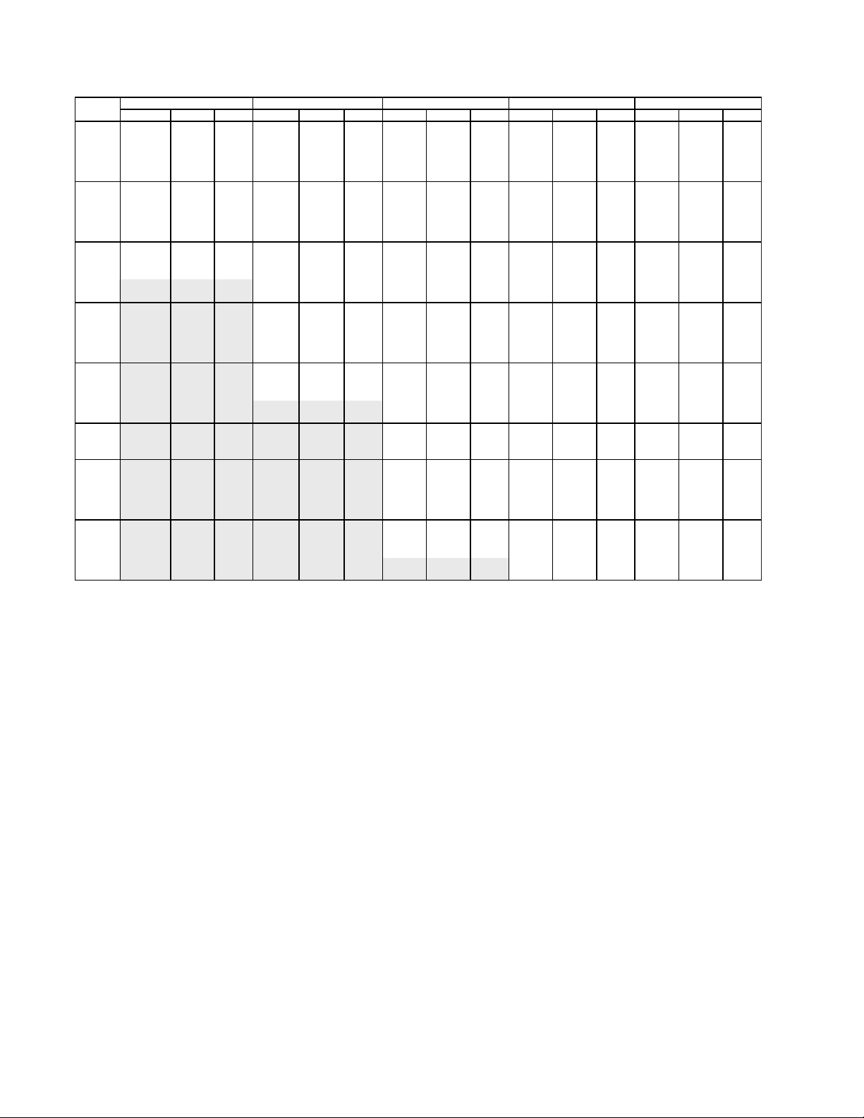
Table 7A - Polyethylene Pressure Drop Table (using 20% methanol @ 30˚F per 100 ft. of pipe)
FLOW 3/4" IPS SDR 11 1" IPS SDR 11 1 1/4" IPS SCH 40 1 1/2" IPS SCH 40 2" IPS SCH 40
RATE PD (ft) Vel ft/s Re PD (ft) Vel ft/s Re PD (ft) Vel ft/s Re PD (ft) Vel ft/s Re PD (ft) Vel ft/s Re
1 0.36 0.55 1162 0.12 0.35 930 0.04 0.21 724 0.02 0.16 621 0.01 0.10 484
2 1.21 1.11 2325 0.42 0.71 1860 0.13 0.43 1449 0.06 0.32 1242 0.02 0.19 967
3 2.47 1.66 3487 0.85 1.06 2789 0.26 0.64 2173 0.13 0.47 1863 0.04 0.29 1451
4 4.08 2.21 4650 1.41 1.41 3719 0.43 0.86 2898 0.21 0.63 2484 0.06 0.38 1935
5 6.04 2.76 5812 2.09 1.77 4649 0.64 1.07 3622 0.31 0.79 3105 0.09 0.48 2418
6 8.30 3.32 6975 2.87 2.12 5579 0.88 1.29 4347 0.42 0.95 3726 0.13 0.57 2902
7 10.87 3.87 8137 3.76 2.48 6509 1.15 1.50 5071 0.55 1.10 4347 0.17 0.67 3386
8 13.74 4.42 9300 4.76 2.83 7439 1.45 1.72 5796 0.70 1.26 4968 0.21 0.77 3869
9 16.88 4.98 10462 5.84 3.18 8368 1.79 1.93 6520 0.86 1.42 5589 0.26 0.86 4353
10 20.30 5.53 11625 7.03 3.54 9298 2.15 2.15 7245 1.03 1.58 6209 0.32 0.96 4837
11 23.99 6.08 12787 8.30 3.89 10228 2.54 2.36 7969 1.22 1.73 6830 0.37 1.05 5320
12 27.93 6.63 13950 9.67 4.24 11158 2.95 2.58 8693 1.42 1.89 7451 0.43 1.15 5804
13 32.13 7.19 15112 11.12 4.60 12088 3.40 2.79 9418 1.63 2.05 8072 0.50 1.24 6288
14 12.66 4.95 13018 3.87 3.01 10142 1.86 2.21 8693 0.57 1.34 6771
15 14.29 5.30 13947 4.37 3.22 10867 2.10 2.37 9314 0.64 1.44 7255
16 16.00 5.66 14877 4.89 3.43 11591 2.35 2.52 9935 0.72 1.53 7739
17 17.79 6.01 15807 5.44 3.65 12316 2.61 2.68 10556 0.80 1.63 8222
18 19.66 6.37 16737 6.01 3.86 13040 2.89 2.84 11177 0.88 1.72 8706
19 21.61 6.72 17667 6.60 4.08 13765 3.17 3.00 11798 0.97 1.82 9190
20 23.64 7.07 18597 7.22 4.29 14489 3.47 3.15 12419 1.06 1.91 9673
21 25.75 7.43 19526 7.87 4.51 15214 3.78 3.31 13040 1.15 2.01 10157
22 27.93 7.78 20456 8.53 4.72 15938 4.10 3.47 13661 1.25 2.11 10641
23 30.19 8.13 21386 9.23 4.94 16663 4.44 3.63 14282 1.35 2.20 11124
24 9.94 5.15 17387 4.78 3.79 14903 1.46 2.30 11608
25 10.67 5.37 18111 5.13 3.94 15524 1.57 2.39 12092
26 11.43 5.58 18836 5.50 4.10 16145 1.68 2.49 12576
28 13.02 6.01 20285 6.26 4.42 17387 1.91 2.68 13543
30 14.69 6.44 21734 7.06 4.73 18628 2.16 2.87 14510
32 16.44 6.87 23183 7.91 5.05 19870 2.41 3.06 15478
34 18.28 7.30 24632 8.79 5.36 21112 2.68 3.25 16445
36 20.21 7.73 26080 9.71 5.68 22354 2.97 3.44 17412
38 22.21 8.16 27529 10.68 5.99 23596 3.26 3.64 18380
40 24.30 8.59 28978 11.68 6.31 24838 3.57 3.83 19347
42 26.46 9.02 30427 12.72 6.62 26080 3.88 4.02 20314
44 28.71 9.45 31876 13.80 6.94 27322 4.21 4.21 21282
46 31.03 9.88 33325 14.92 7.26 28564 4.55 4.40 22249
48 16.07 7.57 29806 4.91 4.59 23216
50 17.26 7.89 31047 5.27 4.78 24184
14
Page 15

Table 7B - Canadian Polyethylene (CSA) Pressure Drop Table (using 20% methanol @ 30˚F per 100 ft. of pipe)
FLOW 3/4" IPS CSA 160 1" IPS CSA 160 1 1/4" IPS CSA 100 1 1/2" IPS CSA 100 2" IPS CSA 100
RATE PD (ft) Vel ft/s Re PD (ft) Vel ft/s Re PD (ft) Vel ft/s Re PD (ft) Vel ft/s Re PD (ft) Vel ft/s Re
1 0.49 0.63 1242 0.17 0.41 996 0.04 0.21 713 0.02 0.16 623 0.01 0.10 498
2 1.66 1.26 2484 0.58 0.81 1992 0.12 0.42 1425 0.06 0.32 1245 0.02 0.20 995
3 3.38 1.89 3726 1.18 1.22 2987 0.24 0.62 2138 0.13 0.48 1868 0.04 0.30 1493
4 5.59 2.52 4968 1.96 1.62 3983 0.40 0.83 2850 0.21 0.63 2490 0.07 0.41 1991
5 8.26 3.15 6210 2.89 2.03 4979 0.59 1.04 3563 0.31 0.79 3113 0.11 0.51 2488
6 11.37 3.79 7452 3.98 2.43 5975 0.81 1.25 4275 0.43 0.95 3735 0.15 0.61 2986
7 14.89 4.42 8694 5.21 2.84 6970 1.06 1.45 4988 0.56 1.11 4358 0.19 0.71 3483
8 18.80 5.05 9935 6.58 3.24 7966 1.34 1.66 5701 0.71 1.27 4980 0.24 0.81 3981
9 23.11 5.68 11177 8.09 3.65 8962 1.65 1.87 6413 0.87 1.43 5603 0.30 0.91 4479
10 27.79 6.31 12419 9.73 4.06 9958 1.99 2.08 7126 1.04 1.59 6225 0.36 1.01 4976
11 32.83 6.94 13661 11.50 4.46 10953 2.35 2.28 7838 1.23 1.74 6848 0.43 1.11 5474
12 38.23 7.57 14903 13.39 4.87 11949 2.73 2.49 8551 1.44 1.90 7470 0.50 1.22 5972
13 43.98 8.20 16145 15.40 5.27 12945 3.14 2.70 9264 1.65 2.06 8093 0.57 1.32 6469
14 17.53 5.68 13941 3.58 2.91 9976 1.88 2.22 8715 0.65 1.42 6967
15 19.78 6.08 14936 4.04 3.12 10689 2.12 2.38 9338 0.73 1.52 7465
16 22.15 6.49 15932 4.52 3.32 11401 2.38 2.54 9960 0.82 1.62 7962
17 24.63 6.90 16928 5.03 3.53 12114 2.64 2.69 10583 0.91 1.72 8460
18 27.22 7.30 17924 5.55 3.74 12826 2.92 2.85 11205 1.01 1.82 8957
19 29.92 7.71 18920 6.10 3.95 13539 3.21 3.01 11828 1.11 1.92 9455
20 32.73 8.11 19915 6.68 4.15 14252 3.51 3.17 12450 1.21 2.03 9953
21 35.65 8.52 20911 7.27 4.36 14964 3.83 3.33 13073 1.32 2.13 10450
22 38.67 8.92 21907 7.89 4.57 15677 4.15 3.49 13695 1.43 2.23 10948
23 41.80 9.33 22903 8.53 4.78 16389 4.49 3.65 14318 1.55 2.33 11446
24 45.03 9.73 23898 9.19 4.98 17102 4.84 3.80 14940 1.67 2.43 11943
25 9.87 5.19 17814 5.19 3.96 15563 1.79 2.53 12441
26 10.57 5.40 18527 5.56 4.12 16185 1.92 2.63 12939
28 12.03 5.82 19952 6.33 4.44 17430 2.19 2.84 13934
30 13.58 6.23 21377 7.15 4.76 18675 2.47 3.04 14929
32 15.20 6.65 22803 8.00 5.07 19920 2.76 3.24 15924
34 16.90 7.06 24228 8.90 5.39 21165 3.07 3.44 16920
36 18.68 7.48 25653 9.83 5.71 22410 3.39 3.65 17915
38 20.53 7.89 27078 10.81 6.02 23655 3.73 3.85 18910
40 22.46 8.31 28503 11.82 6.34 24900 4.08 4.05 19905
42 24.46 8.72 29928 12.88 6.66 26146 4.45 4.25 20901
44 26.54 9.14 31354 13.97 6.97 27391 4.82 4.46 21896
46 28.69 9.55 32779 15.10 7.29 28636 5.21 4.66 22891
48 16.27 7.61 29881 5.62 4.86 23887
50 17.47 7.93 31126 6.03 5.06 24882
Table 7C - Rubber Hose Pressure Drop Table
(using 20% methanol @ 30˚F per 100 ft. of pipe)
FLOW 1" IPS RUBBER HOSE 1 1/2" IPS RUBBER HOSE 2" IPS RUBBER HOSE
RATE PD (ft) Vel ft/s Re PD (ft) Vel ft/s Re PD (ft) Vel ft/s Re
1 0.18 0.41 1000 0.03 0.21 667 0.01 0.10 484
2 0.59 0.82 2000 0.09 0.43 1333 0.02 0.19 967
3 1.21 1.23 2999 0.18 0.64 2000 0.04 0.29 1451
4 2.00 1.64 3999 0.29 0.86 2666 0.06 0.38 1935
5 2.95 2.04 4999 0.43 1.07 3333 0.09 0.48 2418
6 4.06 2.45 5999 0.59 1.29 3999 0.13 0.57 2902
7 5.31 2.86 6998 0.77 1.50 4666 0.17 0.67 3386
8 6.71 3.27 7998 0.98 1.72 5332 0.21 0.77 3869
9 8.25 3.68 8998 1.20 1.93 5999 0.26 0.86 4353
10 9.92 4.09 9998 1.45 2.15 6665 0.32 0.96 4837
11 11.72 4.50 10997 1.71 2.36 7332 0.37 1.05 5320
12 13.64 4.91 11997 1.99 2.58 7998 0.43 1.15 5804
13 15.70 5.31 12997 2.29 2.79 8665 0.50 1.24 6288
14 17.87 5.72 13997 2.60 3.01 9331 0.57 1.34 6771
15 20.16 6.13 14996 2.94 3.22 9998 0.64 1.44 7255
16 22.57 6.54 15996 3.29 3.43 10664 0.72 1.53 7739
17 25.10 6.95 16996 3.66 3.65 11331 0.80 1.63 8222
18 27.74 7.36 17996 4.04 3.86 11997 0.88 1.72 8706
19 30.49 7.77 18995 4.44 4.08 12664 0.97 1.82 9190
20 33.36 8.18 19995 4.86 4.29 13330 1.06 1.91 9673
21 5.29 4.51 13997 1.15 2.01 10157
22 5.74 4.72 14663 1.25 2.11 10641
23 6.21 4.94 15330 1.35 2.20 11124
24 6.69 5.15 15996 1.46 2.30 11608
25 7.18 5.37 16663 1.57 2.39 12092
26 7.69 5.58 17329 1.68 2.49 12576
28 8.76 6.01 18662 1.91 2.68 13543
30 9.88 6.44 19995 2.16 2.87 14510
32 11.07 6.87 21328 2.41 3.06 15478
34 12.30 7.30 22661 2.68 3.25 16445
36 13.60 7.73 23994 2.97 3.44 17412
38 14.95 8.16 25327 3.26 3.64 18380
40 16.35 8.59 26660 3.57 3.83 19347
42 17.81 9.02 27993 3.88 4.02 20314
44 19.32 9.45 29326 4.21 4.21 21282
46 20.88 9.88 30659 4.55 4.40 22249
48 22.50 10.30 31992 4.91 4.59 23216
50 24.16 10.73 33325 5.27 4.78 24184
15
Page 16

CLOSED LOOP INSTALLATION
Prior to installation, locate and mark all existing underground utilities, piping, etc. Install loops for new
construction before sidewalks, patios, driveways, and
other construction has begun. During construction,
accurately mark all ground loop piping on the plot plan
as an aid in avoiding potential future damage to the
installation.
Loop Piping Installation
The typical closed loop ground source system is shown
in Figure 13. All earth loop piping materials should be
limited to only polyethylene fusion in inground sections
of the loop and galvanized or steel fittings should not be
used at any time due to their tendency to corrode by
galvanic action. All plastic-to-metal threaded fittings
should be avoided as well, due to their potential to leak in
earth coupled applications, and a flanged fitting substituted. P/T plugs should be used so that flow can be
measured using the pressure drop of the unit heat
exchanger in lieu of other flow measurement means.
Earth loop temperatures can range between 25-110°F and
2.25 to 3 gpm of flow per ton of cooling capacity is
recommended in any earth loop applications.
Horizontal Applications
To install Horizontal earth couplings, dig trenches using
either a chain-type trenching machine or a backhoe. Dig
trenches approximately 8-10 feet apart. Trenches must be
at least 5 feet from existing utility lines, foundations, and
property lines, and at least 10 feet from privies and wells.
Trenches may be curved to avoid obstructions and may
be turned around corners.
When multiple pipes are laid in a trench, space pipes
properly and backfill carefully to avoid disturbing the
spacing of the pipes in the trench. Figure 14 details
common loop cross-sections used in horizontal loops.
Flow
Controller
AFSC1 or 2
Unit Power
Disconnect
Concrete
block or
brick
Air Pad or Extruded
polystyrene insulation
board
AH5KE
Insulated
Hose Kit
Thermostat
Wiring
P/T Plugs
16
Figure 13 - Typical Closed Loop Application
Page 17

AA
AA
A
A
A
A
A
A
A
A
A
A
AAA
A
A
A
Vertical Bores
One Pair Series/Parallel One Pair
A
A
A
A
A
A
A
A
A
Avg Depth
Two Pair
A
A
A
A
A
A
A
A
A
Avg Depth
Avg Depth
A
A
A
A
A
A
A
A
A
A
When Loops are
shallower than
one ton per loop
A
2 ft
A
2 ft
Two-Pipe Four-Pipe Six-Pipe
Back-Hoe Loops
A
A
2 ft
A
Two-Pipe Four-Pipe
Trenched Loops
Figure 14 - Typical Horizontal Loop Configurations
Vertical Applications
To install Vertical earth couplings, drill boreholes using
any size drilling equipment. Regulations which govern
water well installations also apply to vertical ground loop
installations. Vertical applications typically require
multiple boreholes. Space boreholes a minimum of 10
feet apart. In southern or cooling dominated climates 15
feet is required.
The minimum diameter for 3/4 inch or 1 inch U-bend
well bores is 4 inches. Larger diameter boreholes may be
drilled if convenient, unless local code requires an
expensive method of backfilling. Assemble each U-bend
assembly, fill with water and pressure test prior to
insertion into the borehole.
To add weight and prevent the pipe from curving and
digging into the borehole wall during insertion, tape a
length of conduit, pipe, or reinforcing bar to the U-bend
end of the assembly. This technique is particularly useful
when inserting the assembly into a borehole filled with
water or drilling mud solutions, since a water filled pipe
is buoyant under these circumstances. Tape the pipes
together approximately every 10 feet to prevent the
assembly from separating under downward pressure and
bowing out against the borehole wall.
Carefully backfill the boreholes to within 10 feet of the
surface. Follow IGSPHA specifications for backfilling
unless local codes mandate otherwise.
When all U-bends are installed, dig the header trench 4
to 6 feet deep and as close to the boreholes as possible.
Use a spade to break through from ground level to the
bottom of the trench. At the top of the hole, dig a relief
to allow the pipe to bend for proper access to the header.
The “laydown” header mentioned earlier is a cost
effective method for connecting the bores. Figure 15
illustrates common vertical bore heat exchangers.
AA
AA
AA
2 ft
1 ft
AA
AA
2 ft
AA
2 ft
Extended Slinky
A
A
A
A
A
A
A
A
A
Figure 15 - Typical Vertical Loop Configurations
A
A
A
A
A
A
A
A
A
A
A
A
A
A
A
A
A
A
A
Pond/Lake Applications
Pond loops are one of the most cost effective applications
of geothermal systems. Typically, 1 coil of 300 ft of PE
pipe per ton is sunk in a pond and headered back to the
structure. Minimum pond sizing is 1/2 acre and 8 feet
deep for an average residential home. Actual area can be
1500-3000 ft 2 per ton of cooling. In the north, an ice
cover is required during the heating season to allow the
pond to reach an average 39°F. Winter aeration or
excessive wave action can lower the pond temperature
preventing proper operation of the geothermal system.
Direct use of pond or lake water is discouraged because
of the potential problems of heat exchanger fouling and
pump suction lift. Heat exchanger may be constructed of
either multiple 300’ coils of pipe or slinky style (Figure
16). In northern applications, the slinky or matt style is
recommended due to its superior performance in heating.
Due to pipe and antifreeze buoyancy, pond heat exchanger will most likely need weighted down to prevent
floating. 300 foot coils require two 4” x 8” x 16” blocks
(19 lbs. each) or 8-10 bricks (4.5 lbs each) and every 20
ft of 1-1/4” pipe requires one three-hole brick. Coils are
supported off of the bottom by the concrete blocks or
bricks. The supply/return trenching should begin at the
structure and work toward the pond. Near the pond the
trench should be halted and backfilled most of the way.
A new trench should be started from the pond back
toward the partially backfilled first trench to prevent
pond from flooding back to the structure.
17
Page 18

A
Concrete
Blocks for
weight
Nylon Cable
Ties to secure
blocks
4 ft between
300 ft coil per
ton separated
by scrap pipe
coils
Reverse
Return
Header
3 foot
separation
Heavy Duty
Plastic Safety
matting
Nylon Cable
Ties to secure
Netting and
bricks
8-10 Bricks for
weight
300 ft slinky
coil per ton
Traditional Coiled
Pond Loop - Southern
Climates
Figure 16 - Typical Pond Heat Exchanger Configurations
BUILDING ENTRY
Seal and protect the entry point of all earth coupling
entry points into the building using hydraulic cement.
Slab on Grade Construction
New Construction: When possible, position the pipe in
the proper location prior to pouring the slab. To prevent
wear as the pipe expands and contracts, protect the pipe
with a layer of insulation as shown in Figure 17. When
the slab is poured prior to installation, create a chase
through the slab for the service lines with 4 inch PVC
street elbows and sleeves.
Insulation
Finished Grade
High Efficiency Slinky/Matt
Pond Loop - Northern
Climates
Retrofit Construction
Trench as close as possible to the footing. Bring the loop
pipe up along the outside wall of the footing until it is
higher than the slab. Enter the building as close to the
slab as the construction allows. Shield and insulate the
pipe to protect it from damage and the elements as shown
in Figure 18.
Enter Building As
Soon As Possible
Insulation Inside
Protective Shield
Finished Grade
18
4-6'
Loop Pipe
Figure 17 - Slab on Grade Entry Detail
4-6'
Loop Pipe
Figure 18 - Retrofit Construction Detail
Page 19

Pier and Beam (crawl space)
New and Retrofit Construction: Bury the pipe beneath the
footing and between piers to the point that it is directly
below the point of entry into the building. Bring the pipe
up into the building. Shield and insulate piping as shown
in Figure 19 to protect it from damage.
Horizontal Systems: Test individual loops as installed.
Test entire system when all loops are assembled.
Vertical U-Bends and Pond Loop Systems: Test Vertical
U-bends and pond loop assemblies prior to installation
with a test pressure of at least 100 psi. Either water or air
may be used as the testing medium.
Finished Grade
Insulation Inside
4-6'
Protective Shield
Loop Pipe
Figure 19 - Pier and Beam Entry Detail
Below Grade Entry
New and Retrofit Construction: Bring the pipe through
the wall as shown in Figure 20. For applications in which
loop temperature may fall below freezing, insulate pipes
at least 4 feet into the trench to prevent ice forming near
the wall.
Upon completion of the ground loop piping, pressure test
the loop to assure a leak-free system.
1-1/2” SDR21
1-1/2” PVC
repair coupling
2” hole &
Silcone Caulk
Hydraulic Cement
each side
Footer
Concrete Wall
Final Grade
Dirt Fill
Gravel backfill
PVC Sleeve
Undisturbed Earth
Figure 20 - Below Grade Entry Detail
1-1/4” x 1-1/2” Fernco
gasket coupling
1-1/4” SCH40
PE Pipe
19
Page 20

7300 S.W. 44th Street
Oklahoma City, OK 73179
Phone: 405-745-6000
*69197310*
69197310
ClimateMaster works continually to improve its products. As a result, the design and specifications of each product at the time of order may be changed
without notice and may not be as described herein. Please contact ClimateMaster’s Customer Service Department at 1-405-745-6000 for specific
information on the current design and specifications. Statements and other information contained herein are not express warranties and do not form the
basis of any bargain between the parties, but are merely ClimateMaster’s opinion or commendation of its products.
Rev.: 12/98 © ClimateMaster 1997
FAX: 405-745-2051
www.climatemaster.com
 Loading...