

Page 1
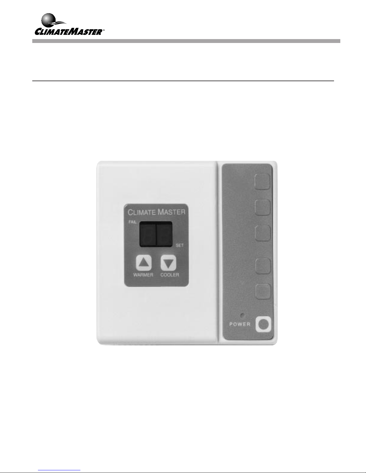
Electronic Thermostat
Installation, Operating &
Maintenance Instructions
ET Series
Page 1
Page 2
GENERAL INFORMATION
Introduction
This Installation, Operation and Maintenance Manual is
for Climate Master ET Series Electronic Thermostats.
ClimateMaster ET Series Thermostats are typically
factory programmed per application requirements and
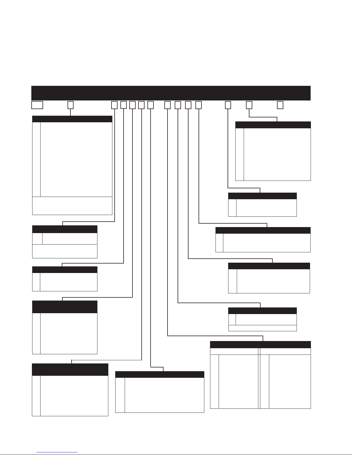
Model Number Digits
12 3 45678 9101112 13 14 15
ET A N 1 B C A M F N A R S C
DIGIT 3 - CONFIGURATION
A ACO, no fan on/auto switches
B ACO w/ fan on/auto switches
C ACO w/ 3 fan speeds
D ACO w/ 3 fan speeds & fan on/
auto switches
E MCO, no fan on/auto switches
F MCO w/ fan on/auto switches
G MCO w/ 3 fan speeds
H MCO w/ 2 fan speeds & fan on/
auto switches
J ACO w/ 3 fan speeds & override
K MCO w/ 2 fan speeds & override
L No buttons
Options "C", "D", "G", "H", "J",
"K" to be used with multi-speed
CMC boards.
shipped under separate cover. No special subbase is
required. An optional ClimateMaster remote sensor is
shipped separately.
Each thermostat has a 15 digit model number printed on
the backplate which identifies thermostat features. Refer
to the decoder below to determine the features provided
DIGIT 14 - SENSOR TYPE
N Room sensor
S Room sensor & 5 minute
anti short-cycle
F Remote sensor - 78"
T Remote sensor & 5 minute
anti short-cycle - 78"
G Remote Sensor - 50'
U Remote Sensor & 5 min.
anti-short cycle - 50'
DIGIT 13 - DRIVE OUTPUT
B Relays & communication
R Relays only
C Communication only
DIGIT 4 - OVERRIDE B
N None
O Override button
Not available when digit 3
is "D", "G", "H"
DIGIT 5 - # OFSTAGES
1 One stage
2 Two stage (CMC style
units only)
DIGIT 6 - EMERGENCY
OVERRIDE SETPOINT
N None
50°F (10°C)
H
80°F (27°C)
C
B50°F (10°C) Heating &
80°F (27°C)
E50°F (10°C) Heating &
88°F (31°C)
DIGIT 7 - TEMPERATURE
A None
68°F (20°C)
B
78°F (26°C)
°
C68
78°F (26°C)
J65
°F (18.3°C) Min on cooling &
80°F (26.7°C) Max on heating
Heating only
Cooling only
Cooling
Cooling
SETPOINT LIMITS
Max on heating &
Min on cooling
F (20°C) Min on cooling &
Max on heating
A Ambient temperature display/
DIGIT 8 - DISPLAY
Press setpoint for setpoint display
B Setpoint display/ Press setpoint for
ambient display
C Setpoint only
D Ambient only
DIGIT 12 - OUTPUT DIRECTION
A Y= Cool, W= Heat
O Y= Comp, W= Rev. Valve on Cooling
B Y= Comp, W= Rev. Valve on Heating
DIGIT 11 - FAN MODE
N Normal (Auto Fan, cycling)
C Continuous fan with power on
H Auto fan on heating, continuous
fan on cooling
DIGIT 10 - TEMP MODE
F Fahrenheit
C Celsius
Field selectable
DIGIT 9 - SETBACK FROM SETPOINT
Setback Only Setup and Setback
N None
C2 F° (1.11 C°)
E4 F° (2.22 C°)
G6 F° (3.33 C°)
J 8 F° (4.44 C°)
M 10 F° (5.56 C°)
R 12 F° (6.67 C°)
T 14 F° (7.78 C°)
V 16 F° (8.89 C°)
N None
B2° F (1.11 C°)
D4° F (2.22 C°)
F6° F (3.33 C°)
H8° F (4.44 C°)
K10° F (5.56 C°)
P12° F (6.67 C°)
S14° F (7.78 C°)
U16° F (8.89 C°)
Page 2
Page 3

with the ET Series thermostats to be installed in your
application.
NOTE: Some options are available only when the
HVAC unit controlled utilizes a ClimateMaster
CMC-2000 Series controller board.
Overview
The ClimateMaster ET Electronic thermostat is intended
for 24 Volt control of heat pumps and conventional
heating and cooling equipment. The thermostat can be
used with standard electromechanical units or with
ClimateMaster units equipped with CMC-2000 Series
Controllers.
Throughout this document, the term UNIT is used to mean
the HVAC unit controlled by the thermostat.
Specifications
The following are general operating parameters and
specifications for the ET Series Electronic Thermostat:
Operating Environment: 0° F (-17.7° C) to 140° F
(60° C) with 5% to 95% relative humidity,
non-condensing.
Storage Environment: 0° F (-17.7° C) to 140° F (60° C)
with 5% to 95% relative humidity, non-condensing.
Power Requirements: 24Volts AC, .14 amps, 50/60 HZ.
Physical Dimensions: The thermostat is 4.6" (11.7 cm)
wide by 4.6 (11.7 cm) high by 1.2" (3 cm) deep. It can be
mounted: on a vertical or horizontal 2"x4"junction box,
or directly on the wall surface.
Relay Ratings: The thermostat relay contacts are rated at
2 amps at 24 Volts. (Terminals are R, Y, W, G, low and
medium.) (Supplied only with "B" or "R" in position
13.)
Serial Port: The thermostat is equipped with a RS-485
standard serial port. Terminals are +N, - N, SHI.
Connections: A terminal strip is provided for Class II
low voltage.
OPERATION
Mode of Operation: The thermostat can be ordered
factory programmed with many operating options for
either Manual Changeover Operation (MCO) or
Automatic Changeover Operation (ACO).
It can also have features which only work when applied
to a unit equipped with a ClimateMaster CMC-2000
Series Controller Board. Each of the eight standard
factory programmed variations is shipped with a custom
faceplate for ease of use.
The following describes some of the more common
operations available on the ET Series Thermostat.
Starting Operation: The HVAC unit is turned on by
pressing the "POWER" button on the thermostat. When
pressed, an LED on the front panel is illuminated.
Thermostat Display: The thermostat can be field
selected to display temperature in either Fahrenheit (°F)
or Celsius (°C). It can also be factory programmed to
display as standard either ambient temperature or
setpoint temperature.
Standard setpoint temperature display may be temporarily masked for five (5) seconds by ambient temperature by pressing both the temperature "UP" and
"DOWN" buttons simultaneously. Standard ambient
temperature display may be temporarily masked for five
(5) seconds by setpoint temperature by pressing either
the temperature "UP" or the temperature "DOWN"
buttons. Display is switched back to standard display
automatically within two (2) seconds after the buttons are
released.
Setpoint temperature display is indicated by a setpoint
indicator dot on the temperature display.
Fan Operation: Fan "AUTO/ON" buttons select whether
the fan runs continuously or if it cycles with the
compressor. A red LED illuminates to indicate the option
selected. When no fan switches are provided on the
thermostat, the fan operation is as specified in the model
number decoder.
Multi-speed Fan Control: When the thermostat offers
multi-speed fan speed control for units with
electromechanical controls and three speed capability,
then high speed connects to G1, medium speed to
"MED" and low speed to "LOW".
See the CMC-2000 Series Installation, Operation and
Maintenance Manual for more information on fan speed
control.
MCO Operation: When the thermostat is factory
programmed with an MCO option it must be manually
set to either heating or cooling. MCO thermostats have a
"HEAT" and a "COOL" button. The MCO thermostat can
be equipped with or without fan switches or with either
automatic or two speed fan operation.
Page 3
Page 4
ACO Operation: When the thermostat is factory
programmed with an ACO option, it automatically changes
from heating to cooling. ACO thermostats have a
"POWER" button. The ACO thermostat can be equipped
with or without fan switches or with either automatic fan or
three speed fan operation.
Emergency Override: The ET Series Thermostat can be
ordered with a factory programmed emergency override
option. This option monitors room temperature as long as
power is available to the thermostat even when the power
button is turned "OFF".
This option may be ordered to maintain a room temperature
minimum of 50° F (10° C), a maximum room temperature
of 80° F (26.7° C) or both minimum and maximum limits.
Refer to the decoder on page 2 to determine if this option is
included with the installed thermostat.
CMC-2000 Series Operation: A thermostat intended to
operate with a unit equipped with a CMC-2000 Series
controller operates with the following unique sequences:
Multi-speed fan control is handled through the RS-485
interface between the thermostat and the controller.
When an override button is provided, the unit overrides
night setback for two (2) hours after being activated by
pushing the "OVERRIDE" button. In night setback mode,
the thermostat displays the factory programmed night
setback temperature, provided the thermostat normally
displays set-point temperature. When the override button is
pressed, setpoint returns to the normal day setting for two
(2) hours. (See Night Setback on page 8 for more
information.)
Two stage Operation is provided for use with units
equipped with CMC-2000 Series Controllers. Units must be
addressed as shown in the ClimateMaster CMC-2000 Series
Installation, Operation and Maintenance Manual. The first
stage CMC-2000 Series controller must have dip switches
set to address one and the second stage controller must have
dip switches set to address two. Units must be powered
down before dip switch settings are changed. Note: The
CMC-2000 Series controller must have these dip switch
settings for two stage operation even when the thermostat is
not working with DDC communications.
When the CMC-2000 Series Controller board is equipped
with an optional fan control, the thermostat can be set at
"HI", MED" or "LOW" fan speeds. A red LED indicates
which speed is selected.
Fault Indicator: When the thermostat is used with units
equipped with a fault output, the LED light indicates that a
fault has occurred. This feature is standard on
ClimateMaster units with CMC-2000 Series Controllers
without an additional wire. It is an option on other
electromechanical equipment.
When this feature is an option, the fault wire is connected to
terminal "X" on the back of the thermostat. The fault light
operates on 24 VAC or 24 VDC.
INSTALLATION
!
▲
WARNING
To prevent electrical shock or equipment damage,
disconnect power supply before installing.
The installation of the ET Series Electronic Thermostat
must be in accordance with the regulations of ALL
Authorities having jurisdiction and MUST conform to all
applicable Codes. It is the responsibility of the Installing
Contractor to determine and comply with ALL applicable
Codes and Regulations. Installer MUST be an
experienced service technician trained in the installation
of this type of equipment.
Pre-Installation
Installation, operating and maintenance instructions are
provided with each thermostat. Before start-up, read all
manuals and become familiar with the thermostat and its
operation.
Verify that the unit to be controlled by the thermostat is
installed and ready for operation.
Check the applications and correctly match the
thermostat with the unit to be controlled.
Field supply and install an optional electrical junction
box following location instructions listed below.
Determine which of the field wiring diagrams shown on
pages 6 and 7 are to be used.
Location
Install the thermostat approximately 4 feet (1.22 meters)
above the floor in an area exposed to circulating room
air of average room temperature.
The ET Series Electronic Thermostat must be installed
in accordance with the following guidelines:
• Install on an interior wall only. Do not install on an
exterior wall.
• Install out of direct sunlight.
• Install at some distance from air discharge grilles. Do
not directly expose to hot or cold discharge air.
• Install out of drafty areas and dead air spaces.
Page 4
Page 5
Mounting
4.47"
1.86"
1.17"
1.17"
2.81"
5.62"
.07"
Electrical Wiring
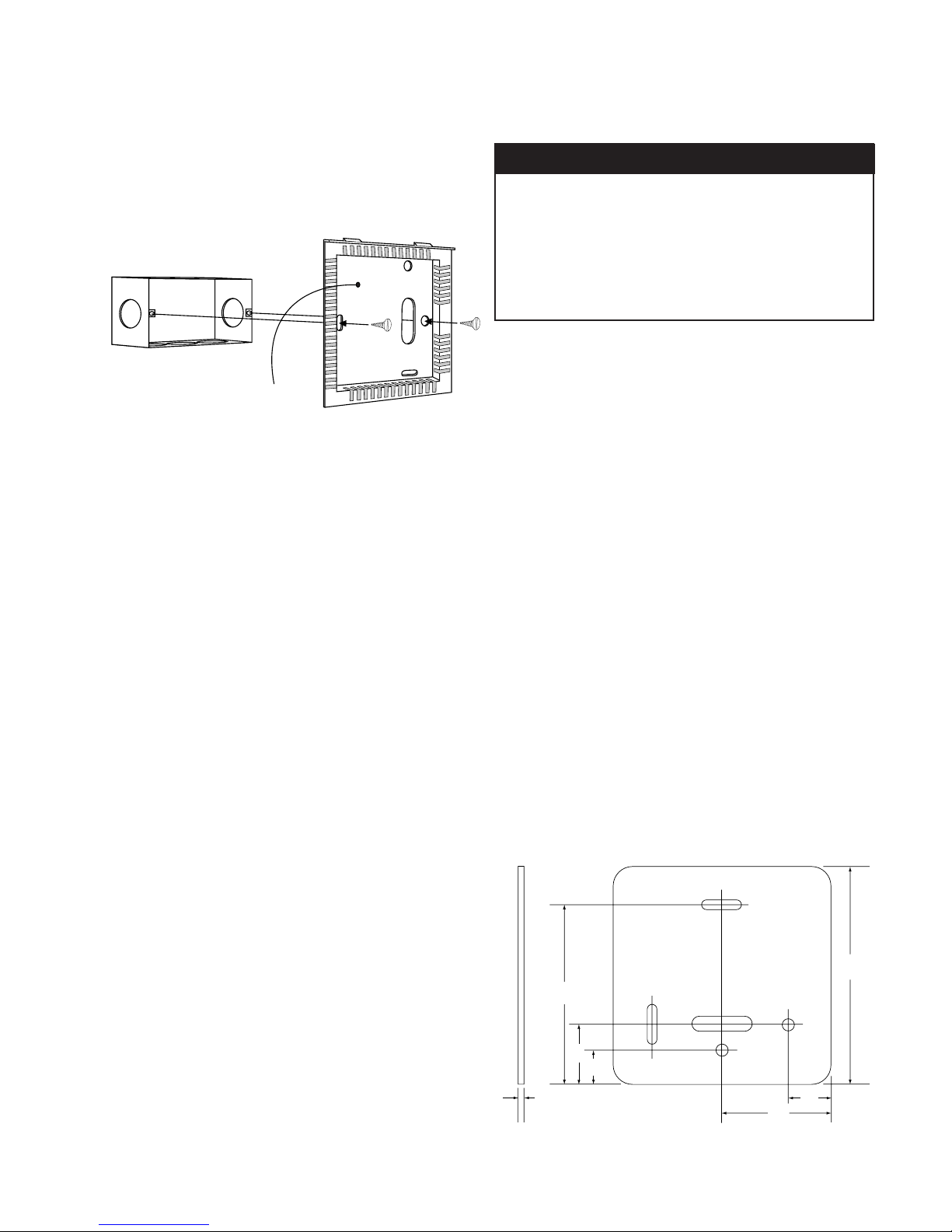
Mount the ET Series Electronic Thermostat as shown
in Figure 1.
Figure 1
ET Series Installation
Green ground wire to be wired
to SHI on thermostat.
1) Remove the thermostat from the shipping carton.
2) Check part number on the back to ensure that it is
correctly matched to the unit to be controlled.
3) Remove the thermostat back from the thermostat with
the Allen key provided.
4) Pull the control wire through the back plate.
5) Attach the thermostat to the field supplied and installed
electrical junction box using the two screws provided. If
the thermostat is to be mounted directly on the wall, use
the backplate as a template and mount using appropriate
field supplied hardware.
6) Connect the control wires to the screws on the thermostat per the appropriate wiring diagram illustrated in
Figure 3 (page 6). Attach only one wire per terminal.
7) Replace the backplate using the Allen key provided.
Deco Panel: When the thermostat is provided with a deco
panel (ClimateMaster part no. 69602912), mount the deco
panel between the mounting plate and the wall using the
screws provided with the thermostat. (See Figure 2 below
for dimensions.)
!
▲ CAUTION
To avoid equipment damage, turn power OFF before
making all wiring connections.
NOTE: For use with CMC 2000 Controls, power must
be OFF to the CMC 2000 Controller before
connecting the thermostat. If power is left ON, the
CMC 2000 Controller will not communicate with the
ET Series thermostat.
Wire thermostats for use with units using CMC-2000
Series Controllers as shown in Figure 3 (page 6). Note
that the wire should be a four (4) conductor, shielded
cable. Refer to the CMC-2000 Series IOM for recommended types wire.
Wire thermostats for use with ClimateMaster units with
electromechanical controls as shown in Figure 4 (page 6).
Wire other equipment with electromechanical controls as
shown in Figure 5 (page 6). Note: This drawing shows
"W1" configured as an "O" terminal. The thermostat is
also available with "W1" configured as a "B" terminal.
Remote Sensor: An optional ClimateMaster remote
sensor can only be installed with an ET Series Thermostat
equipped with a two pin connector mounted inside the
thermostat for that purpose. The sensor is available with
either a 78 inch (198.12 cm), pre-formed cable
(part no. 69626517) or a 50 foot (152.4 m), pre-formed
cable (part no. 69626518). The thermostat shall be factory
calibrated for the length ordered.
Figure 2
Deco Panel for ET SERIES Thermostat (p/n 69602912)
Page 5
Page 6
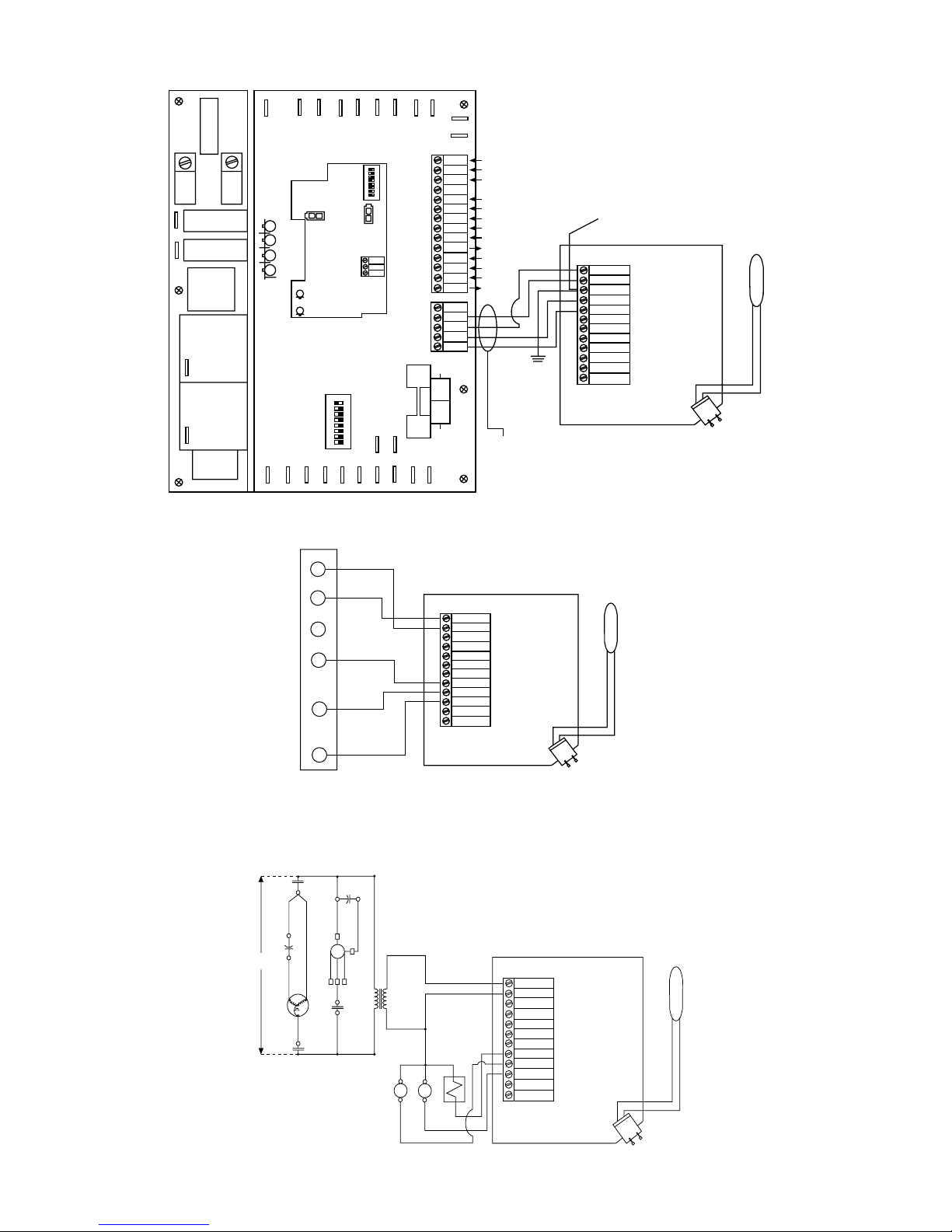
Figure 3
S/N
J1
L1
L2
LOW
FAN
MED
FAN
FAN-HI COMP
COND
HPS
LPS
LTS
LEAVING
WATER
TEMP
COMMUNICATION
ADAPTER
RECEIVE
TRANSMIT
1 2 3 4 5 6 7 8
ON
1 2 3 4 5 6 7 8
ON
SHI
-
N
N+
C3
C4
DIP
SWITCHES
DISCHARGE
AIR TEMP
J4
J2
P3
P4
P2
C2
TEST
UNIT SHUTDOWN
USD
CSD
COMP. SHUTDOWN
ESD
EMERGENCY SHUTDOWN
GND
LOW
FAN
MED
FAN
HI
FAN
C
COM. FLOATING
L
OVERRIDE
FAIL
X
G
FAN HI
COOL
Y1
HEAT
W1
R
24VAC
SHI
GND
24V
NN+
SHIELDED
CABLE
GREEN WIRE
ON BACKPLATE
24 VAC
COM
SHI
N-
N+
X
W
Y
G
CHASSIS
GROUND
MED
LOW
THERMOSTAT FIELD WIRING
TO CLIMATEMASTER
(OPTIONAL)
REMOTE
AMBIENT
SENSOR
ONE STAGE HEAT PUMP
WITH CMC CONTROLLER
Figure 4
5
R
24 VAC
Y1
0
Y2
COM
SHIELD
N-
N+
X
W
Y
G
MED
LOW
(OPTIONAL)
REMOTE
AMBIENT
SENSOR
Page 6
Figure 5
265V / 1 PH / 60HZ
POWER SUPPLY
G
T.B.
(IN UNIT)
THERMOSTAT FIELD WIRING TO CLIMATEMASTER
SINGLE STAGE HEAT PUMP WITH ELECTROMECHANICAL CONTROLS
L2
CC
CC
L2L2NEUTRAL
BMC
T2
1
CRC
BM
2
(HI)
(MED)
(LOW)
345
1
R
S
3
C
T1
L1
L1 L1
TRANS
265V
24 VAC
BR
R.V.
BRCC
24 VAC
COM
SHIELD
N-
N+
X
W
Y
G
MED
LOW
THERMOSTAT FIELD WIRING TO OTHER THAN
CLIMATEMASTER UNIT ELECTROMECHANICAL CONTROLS
(OPTIONAL)
REMOTE
AMBIENT
SENSOR
Page 7
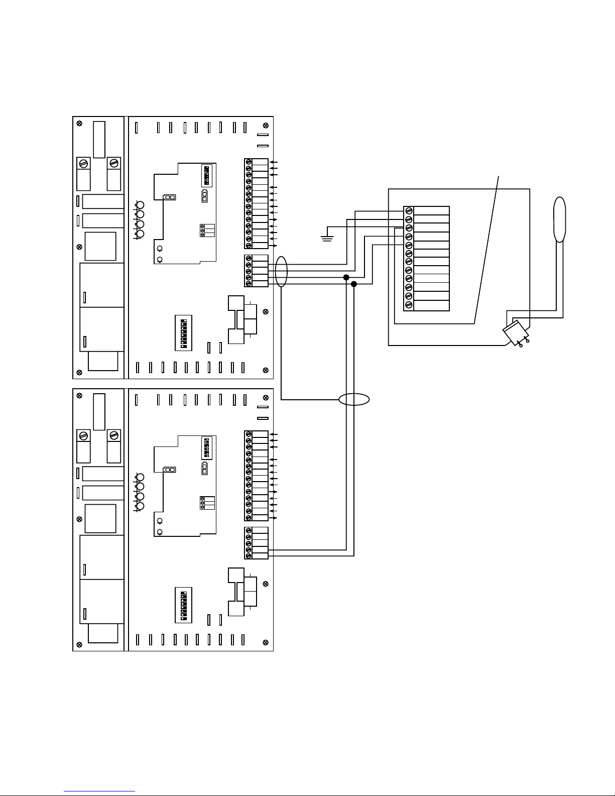
Figure 6
Thermostat field wiring to a two stage unit with CMC 2000 Series Controller
S/N
J1
1 2 3 4 5 6 7 8
ON
SHI
-
N
N+
DIP
SWITCHES
DISCHARGE
AIR TEMP
J4
J2
FAN
FAN
LOW
MED
FAN-HI COMP
L1
COND
HPS
LPS
LTS
LEAVING
WATER
TEMP
COMMUNICATION
ADAPTER
RECEIVE
TRANSMIT
L2
TEST
UNIT SHUTDOWN
USD
COMP. SHUTDOWN
CSD
EMERGENCY SHUTDOWN
ESD
GND
LOW
FAN
FAN
MED
FAN
HI
COM. FLOATING
C
OVERRIDE
L
FAIL
X
FAN HI
G
COOL
Y1
HEAT
W1
24VAC
R
SHI
GND
24V
NN+
CHASSIS
GROUND
24 VAC
COM
SHI
N-
N+
X
W
Y
G
GREEN WIRE
ON BACKPLATE
(OPTIONAL)
REMOTE
AMBIENT
SENSOR
MED
LOW
ON
1 2 3 4 5 6 7 8
C3
P3
C4
P4
C2
P2
THERMOSTAT FIELD WIRING
TO CLIMATEMASTER
TWO STAGE HEAT PUMP
WITH CMC CONTROLLERS
Sheilded Cable
S/N
TEST
UNIT SHUTDOWN
USD
CSD
J1
1 2 3 4 5 6 7 8
ON
SHI
-
N
N+
DIP
SWITCHES
DISCHARGE
AIR TEMP
J4
J2
FAN
FAN
LOW
MED
FAN-HI COMP
L1
COND
HPS
LPS
LTS
LEAVING
WATER
TEMP
COMMUNICATION
ADAPTER
RECEIVE
TRANSMIT
1 2 3 4 5 6 7 8
ON
L2
COMP. SHUTDOWN
ESD
EMERGENCY SHUTDOWN
GND
LOW
FAN
MED
FAN
HI
FAN
C
COM. FLOATING
L
OVERRIDE
FAIL
X
G
FAN HI
COOL
Y1
HEAT
W1
R
24VAC
SHI
GND
24V
NN+
NOTE: Set the first stage CMC Board dip switch to
C3
P3
address no. 1 and the second stage CMC Board to
address no. 2. See CMC 2000 Electronic Controller
C4
P4
C2
P2
Version 8.9 I.O.M., part no. 69626515, for details.
Page 7
Page 8
UNIT START-UP
▲ CAUTION!
To avoid equipment damage, DO NOT attempt to
checkout thermostat operation without verifying that
the unit to be operated is installed and ready to be
operated.
NOTE: For use with CMC 2000 Controls, power must
be OFF to the CMC 2000 Controller before connecting
the thermostat. If power is left ON, the CMC 2000
Controller will not communicate with the ET Series
thermostat.
1) Starting the Unit: Press the "POWER" button. The
LED should illuminate. If the LED is not illuminated,
verify that unit power is turned on and check for 24 Volts
at the thermostat terminal.
2) MCO thermostat: Push "HEAT" button and raise
setpoint above ambient temperature. Within a few
seconds the unit should begin to operate. Push "COOL"
button and lower setpoint below ambient temperature.
This should stop compressor and fan operation. If the
thermostat is equipped with an anti short-cycle timer or is
used with a CMC-2000 Series Control board supporting
an anti short-cycle timer, the unit should begin to operate
in cooling mode after a 5 minute time delay. Raise the
setpoint until the unit stops operating.
3) ACO thermostat: Raise setpoint above ambient
temperature. Within a few seconds the unit should begin
operating. Lower setpoint below ambient temperature.
This should stop compressor and fan operation. If the
thermostat is equipped with an anti short-cycle timer or is
used with a CMC-2000 Series Control board supporting
an anti short-cycle timer, the unit should begin to operate
in cooling mode after a 5 minute time delay. Raise the
setpoint until the unit stops operating.
4) Operating Faults: If at anytime the fault light illumi-
nates check the unit for operational problems. Refer to the
IOM supplied with the unit for trouble-shooting information.
5) Fahrenheit/Celsius Setting: To switch the reading on
the thermostat from Fahrenheit (°F) to Celsius (°C) (or
from Celsius to Fahrenheit), hold the power button down
for 30 seconds and then release.
6) Night Setback: When the thermostat is connected to a
unit with a CMC 2000 Series Controller and night setback
is initiated (see CMC 2000 Series Installation, Operation
and Maintenance Manual, page 6), the setpoint adjustment buttons are locked. The thermostat will display the
night setback setpoint provided the thermostat normally
displays setpoint. Two (2) hour day operation can be
activated by pressing the override button. When the
override button is pressed, the setpoint adjustment buttons
are unlocked, and the setpoint returns to the day setpoint.
Part #:69197318
ClimateMaster works continually to improve its products. As a result, the design and specifications of each product at the time of order may be changed
without notice and may not be as described herein. Please contact ClimateMaster’s Customer Service Department at 1-405-745-6000 for specific
information on the current design and specifications. Statements and other information contained herein are not express warranties and do not form the
basis of any bargain between the parties, but are merely ClimateMaster’s opinion or commendation of its products.
1-08-IM103 © ClimateMaster 1994 Rev. 4/98
7300 S.W. 44th Street
Oklahoma City, OK 73179
Phone: 405-745-6000
Fax: 405-745-6058
www.climatemaster.com
 Loading...