


DOAS CM3500
Controller
Table of Contents
Dehumidifi cation Equipment Standard Limited Warranty 3
Installation 4
IAQ Controller Details 7
Service Menu 17
Factory Confi guration 23
Alarm Menu 29
Remote Room Sensor Confi guration 32
Hardware Details 33
Specifi cations 35
Points List 39
Revision History 48
Application, Operation
& Maintenance
97B0065N01
Rev: 31 July, 2013

CLIMATEMASTER WATER-SOURCE HEAT PUMPS
DOAS CM3500 Controller
Rev.:31 July, 2013
This Page Intentionally Left Blank
2
ClimateMaster Water-Source Heat Pumps

THE SMART SOLUTION FOR ENERGY EFFICIENCY
DOAS CM3500 Controller
Rev.:31 July, 2013
Dehumidifi cation Equipment Standard Limited Warranty
CAUTION!
CAUTION! ONLY TRAINED, QUALIFIED PERSONNEL
SHOULD INSTALL AND/OR SERVICE CLIMATEMASTER.
SERIOUS INJURY, DEATH AND PROPERTY DAMAGE
CAN RESULT FROM IMPROPER INSTALLATION/SERVICE
OF THIS EQUIPMENT HIGH VOLTAGE ELECTRICAL
COMPONENTS AND REFRIGERANT UNDER PRESSURE
ARE PRESENT.
DEHUMIDIFICA TION EQUIPMENT
ST ANDARD LIMITED WARRANTY
ClimateMaster warrants the dehumidifying unit to be free
from defects in materials and workmanship subject to the
terms, conditions and limitations stated herein.
Terms
ClimateMaster warrants all components (except as noted)
for a period of two (2) years from the date of shipment.
This warranty shall be limited to the supply of new or
rebuilt parts for the part which has failed because of
defects in workmanship or material, and does not include
the cost for labor, transportation or other costs not herein
provided for. Replaced parts are warranted only for the
remaining portion of the original warranty period.
Conditions - The warranty is subject to the following
conditions:
7. This warranty shall be null and void if defects or
damages result from unauthorized opening of the
refrigerant circuit, tampering with factory set controls,
or operating outside the original design conditions.
8. ClimateMaster shall not be liable for labor costs
incurred in diagnosing the problem, or the removal or
replacement of the part or parts being repaired.
9. ClimateMaster must preauthorize all warranty
coverage described herein.
Extended Warranty
Your ClimateMaster unit may have extended warranties
beyond this Standard Limited Warranty document.
Extended warranties are only available at the time of the
purchase of the original equipment. These extended
warranties are covered under a separate document
and their terms and conditions are separate from
this document. It is mentioned in this document for
informational purposes only. Any and all incidental or
consequential damages are expressly excluded from
this warranty. Some states do not allow the exclusion of
incidental or consequential damages for personal injury,
so the above limitations may not apply to you for certain
damages. This warranty gives you specifi c legal rights,
and you may also have other rights, which vary from state
to state. No person or representative is authorized to
make any warranty or assume any liability not strictly in
accordance with the aforementioned.
1. The unit must be properly installed and maintained in
accordance with the ClimateMaster “Installation and
Operation Manual” provided with each unit and/or
other documentation provided.
2. The Start-Up Report must be completed and returned
to ClimateMaster within 30 days of the start-up.
3. This warranty shall not apply to any part that has
been tampered with, or has been subject to misuse,
negligence or accident. A warranty can be obtained for
altered equipment but only with written consent from
ClimateMaster.
4. The following parts and components are excluded
from the warranty: belts, fi lters, driers, fuses and
refrigerant.
5. Refrigerant coils or other components that corrode
due to improperly balanced pool chemistry or
corrosive air quality will not be warranted.
6. All replacements or repairs will be FOB Oklahoma
City, OK.
climatemaster.com
3

CLIMATEMASTER WATER-SOURCE HEAT PUMPS
DOAS CM3500 Controller
Rev.:31 July, 2013
Installation
Your ClimateMaster controller is designed for precise
monitoring and control of air temperature and relative
humidity (RH) within a conditioned environment. This
CM3500 control system is easy to install and operate. It
features either an internal display terminal (IDT), as part of
the controller, or a wall-mountable remote display terminal
(RDT), in cases where the controller mounted display or IDT
would prove hard to view or use. Both allow you to view and
adjust setpoints and modes of operation. They also indicate
the operating status of major components inside of the
dehumidifi er. Most sensors and inputs have been factory-
installed and wired inside of the dehumidifi er. In most cases,
you need only mount and wire the supply air temperature
sensor and, if provided, the RDT. The RDT, which is simply
an interface tool, contains no sensors. You do not need to
install it in the room you wish to dehumidify. If purchased
with your system, CO2 and remote room sensors may
require mounting as well.
Your controller is provided with a duct-mountable
temperature sensor for the supply air. If the unit was
purchased with the zone reset option, it also has one or
multiple remote room sensors. Additionally, if the unit
was purchased with the CO2 option, it has an indoor and
outdoor CO2 sensor.
• A duct-mount sensor is normally used in applications
where continuous blower operation is desired. A
duct-mount sensor helps ensure consistent conditions
throughout the space. Install the duct-mount sensor in
the supply air duct.
• ClimateMaster DOAS ordered with the zone reset
option are supplied with a remote room sensor. Up to
CAUTION!
CAUTION! A potential drawback of this sensor is that it
relies on a continuous stream of air moving past it. Using a
duct-mount sensor with a non-continuous blower may lead to
short-cycling of the refrigeration compressor..
four of these sensors may be wired to the system.
This wall-mountable display is an IP30 rated device
Operating conditions must be between 32.0°F and
120.0°F and less than 85% RH. The controller’s RS485
Figure 1: CM3500 Room Sensor
serial interface communicates via three-way plug-in
terminals. Install a twisted pair plus shielded cable,
20-22 AWG. Total length of the network must not
exceed 1,500 feet. The capacitance between the wires
must not exceed 90 pF/M. (See your wiring schematic
for connection details.) These remote devices require
a separate 24Vac 50/60HZ 1.5VA power connection.
Provide a dedicated 250 mAT fuse for each sensor.
Use a class 2 safety transformer with a minimum
rating of 4VA. If the sensor is wired to F1 and F2 of
the dehumidifi er control panel terminal, G0 must be
connected to F2.
• ClimateMaster DOAS ordered with the CO2
control package require sensors for the indoor
CAUTION!
CAUTION! Undersized wiring will cause inaccurate sensor
readings. Do not run sensor wiring adjacent to, OR in the
same conduit as, wires carrying more than 24 V AC.
Figure 2: CO2 Sensors
CAUTION!
CAUTION! Do not mount the sensor in a section of duct where
false readings may occur due to dead air regions, solar heat
gain or thermal losses in winter. Do not mount the sensor where
water is likely to drip on it. Install two (2), 18 gauge (0-500 feet)
OR two (2), 24 gauge (0-100 feet) wires from the sensor to the
labeled terminal strip in the control panel of the dehumidifi er.
(See your wiring schematic for connection details.)
CAUTION!
CAUTION! Undersized wiring will cause inaccurate sensor
readings. Do not run sensor wiring adjacent to, OR in the
same conduit as, wires carrying more than 24 VAC.
4
ClimateMaster Water-Source Heat Pumps

THE SMART SOLUTION FOR ENERGY EFFICIENCY
DOAS CM3500 Controller
Rev.:31 July, 2013
and outdoor CO2 levels. These measurements are
used to determine the CO2 differential level in the
conditioned space. This differential is the variable
compared to the CO2 setpoint and used in the
control loop to provide more or less outdoor air into
the conditioned space. The outdoor CO2 sensor is
installed in a protective enclosure and is designed to
operate in outdoor conditions ranging from -40°F to
158°F. 24VAC power is required for this device and
the output is 4-20mA. (See your wiring schematic for
connection details.) The indoor CO2 sensor is installed
in a high impact ABS enclosure and has an operating
temperature range of 32°F to 122°F. 24VAC power is
required for this device and the output is 4-20mA.
(See your wiring schematic for connection details.)
Note: You must use the ClimateMaster CM3500 control
system to control or interlock with the room heating system.
CAUTION!
CAUTION! Do not run sensor wiring adjacent to, OR in the
same conduit as, wires carrying more than 24 VAC.
This prevents wide fl uctuations in room air temperature. It
also prevents the heater from trying to heat the room while
the dehumidifi er is running in the cooling mode.
• The standard ClimateMaster CM3500 Controller
provides a dry contact closure to operate the auxiliary
space heater. The contact closes to energize a heater
(may be supplied by others) which has its own power
source. Install two wires from the thermostat terminal
blocks on the heater to the terminal strip on the control
panel of the dehumidifier. (See your wiring schematic
for connection details.)
• As an option, ClimateMaster will provide a
proportional 0-10 VDC direct-acting signal to
modulate a heating coil control valve or other auxiliary
modulating heater. Most proportional valves have
either three (3) or four (4) terminals for fi eld-installed
wiring.
a. Four-terminal valves have two terminals for 24 VAC
power and two terminals for the signal input.
b. Three-terminal valves have one terminal for the
“hot” 24 VAC input, a second terminal for the
“positive” signal input and a third, common
terminal for the “neutral” 24 VAC input and the
“negative” signal input. You must follow the
instructions included with the valve cut sheet.
Observe the proper polarity or you may damage
both the valve and the controller. (See your wiring
schematic for connection details.)
The optional RDT must be mounted in a dry, noncorrosive environment. Operating conditions must be
between 0.0°F and 140.0°F and less than 90% RH.
The optional RDT is an IP40 device and is powered
through the cable provided. If a longer length is required,
there are two options. For locations of the RDT up to 150
feet, use a standard 24 AWG, 6 conductor phone cable.
CAUTION!
CAUTION! Moisture can damage the circuitry of the
display. The display can either be mounted directly to the
dehumidifi er or located up to 20 feet away using the cable
that came with the display.
For locations of the sensor up to 1,500 feet, use 22 AWG,
3 twisted pair cable. (See your wiring schematic for connection details.) Pull the connector through the hole in
the back of the mounting bracket. Attach the bracket to
the wall. After plugging the cord into the back of the RDT,
feed any extra wiring back into the hole of the mounting
bracket and gently snap the RDT into the bracket.
CAUTION!
CAUTION! Do not run the RDT wiring in the same conduit
as, OR adjacent to wires carrying over 30 VAC.
Figure 3: Optional RDT
climatemaster.com
5

CLIMATEMASTER WATER-SOURCE HEAT PUMPS
DOAS CM3500 Controller
Rev.:31 July, 2013
The CM3500 microprocessor controller is a powerful,
fl exible controller with many useful features including:
• Display of room air temperature, relative humidity and
refrigerant pressures.
• Display of equipment operating status such as
dehumidification and cooling.
• Display of alarms for abnormal conditions such as
sensor failures or tripped safety controls.
• An optional seven-day occupancy timer which can
control outdoor air dampers (if used) to bring in fresh
air when the dehumidifier is an occupied state.
• A convenient, easy-to-understand display interface
which allows the operator to view and change
setpoints and time schedules.
The remote terminal allows the operator to monitor the
operation of the dehumidifi er and view the alarm screens
and history to insure proper dehumidifi er operation. It is
important that the remote terminal remains functional for
safe and effi cient unit operation. If you think the remote
terminal is not functioning correctly, refer to the table in
Section 1.7.1 that follows.
• The RDT allows the operator to monitor the operation
of the dehumidifier and view the alarm screens and
history to ensure proper dehumidifier operation. It
is important that the RDT remains functional for safe
and efficient unit operation. If you think the RDT is not
functioning correctly, refer to table 1 that follows.
Table 1: RDT Troubleshooting
Problem Solution
No LEDs lit on the remote
terminal.
Remote terminal shows:
“NO LINK”.
Red alarm LED is lit.
If the remote terminal is not functioning after review of the above, consult
ClimateMaster’s Service Department at (405) 745-6000.
No power is getting to the remote
terminal. Check fi eld wiring between
remote terminal and controller.
The display address has been altered.
Press the UP, ENTER and DOWN keys
together for 4 seconds and set the display
address to 32.
The system has experienced an alarm
and is waiting for it to be acknowledged.
Press ENTER from the Alarm Screen.
If the red LED stays lit, clear the alarm
condition and then press ENTER from the
Alarm Screen.
6
ClimateMaster Water-Source Heat Pumps

THE SMART SOLUTION FOR ENERGY EFFICIENCY
DOAS CM3500 Controller
Rev.:31 July, 2013
IAQ Controller Details
Figure 4: Remote Display Terminal
Figure 5: Internal Display Terminal
Menu Overview and General Instructions
The CM3500 Controller is pre-programmed and
confi gured at the factory for use in the application you
have specifi ed. The remote display terminal (RDT -
Figure 4) or the internal display terminal (IDT - Figure 5)
allows the operator to monitor and adjust the setpoints
of your ClimateMaster DOAS. The RDT has an LCD
screen and 6 keys. The keys on the left hand side of the
remote terminal, top to bottom, are the ALARM key
shown as an alarm bell, PROGRAM key abbreviated
“Prg” and the ESCAPE key abbreviated “Esc.” The
keys on the right hand side of the remote terminal, top
to bottom, are the UP key shown as an up arrow, the
ENTER key shown as a left arrow and the DOWN key
shown as a down arrow. The IDT also has an LCD screen
and 6 keys. The keys on the top row to the right of the
LCD screen are the ALARM key shown as an alarm bell,
PROGRAM key abbreviated “Prg” and the ESCAPE key
abbreviated “Esc.” The keys on the bottom row to the
right of the LCD screen are the UP key shown as an up
arrow, the DOWN key shown as a down arrow and the
ENTER key shown as a left arrow.
The Home Screen, displaying the ClimateMaster
logo, shows 2 items below it; the current supply air
temperature and the current unit status. The IAQ
displayed in the upper right of the screen indicates
that the product series of the program installed in the
controller is for Indoor Air Quality. Below this line, “Esc
Menu” indicates that if the Esc key is pressed, the Main
Menu will be displayed. Pressing Esc on any other screen
will take you back one screen. Menu screens allow the
user to select from a series of actions. The action that
is capitalized on the screen is selected by pressing the
ENTER key. To cycle through the selections on a menu
screen, use the UP and DOWN keys. If setpoints or
selections can be altered on a screen, the ENTER key
will cycle through those items. Once the cursor is over
an item, the UP and DOWN arrow keys will modify the
setting. Numeric values require that the ENTER key be
pressed to accept the value. An “on” or “off” selection is
altered as soon as the UP or DOWN keys are pressed. To
view the alarms from any menu, simply press the ALARM
key. The UP and DOWN keys will display any active
alarm. When an alarm is triggered, the red LED behind
the ALARM key will light and remains on until the alarm
is acknowledged. Alarm acknowledgement and history
instructions are shown on the main Alarm Screen. To
escape from the alarm screens, press the Esc key and the
Home Screen will be displayed. Screens which display a
small up arrow in the upper right and a small down arrow
in the lower right are part of a series of screens which can
be accessed by pressing either the UP or DOWN arrow
keys. If the operator has not pressed a key for an hour,
the remote terminal will return to the Home Screen.
Main Menu
Pressing the Esc key from the Home Screen displays the
MAIN MENU (Figure 6). This menu allows the operator
to select the STATUS MENU, Setpoint Menu, set a
Temporary Occupancy, change the Occupancy Schedule
and view the Unit Revision.
Figure 6: Main Menu
climatemaster.com
7

CLIMATEMASTER WATER-SOURCE HEAT PUMPS
DOAS CM3500 Controller
Rev.:31 July, 2013
To return to the Home Screen, press the Esc key.
• Status Menu - Selecting the STATUS MENU from the
MAIN MENU allows access to the Modes & Time, I/O
Status and Starts & Run Times.
Figure 7: Status Menu
To return to the MAIN MENU, press the Esc key.
• Modes & Time - Selecting Modes & Time from
the SERVICE MENU displays a text explanation
of the unit. The Occupied state (either Occupied
or Unoccupied) is shown as well as the unit status.
The Unit Status will show one of the following
states:
To return to the STATUS MENU, press the Esc key.
• I/O Status - Selecting the I/O Status from the
STATUS MENU displays Digital Inputs, Analog
Inputs, Digital Outputs and Analog Outputs.
Room Sensor Data and Expansion I/O will also be
shown on this screen if these options were purchased with the IAQ system.
To return to the STATUS MENU, press the Esc key.
Figure 9: I/O Status
• Zone Satisfied/Off
• Heating Required
• Cooling Required
• Dehumidifying
• Dehumid/Heat
• Dehumid/Cool
• Low Suction Pressure
The Compressor Command On/Off, Auxiliary Heat
On/Off and current date and time will also be
shown. If any compressor is waiting for its nonshort cycling timer to time out, this will be shown
here as well.
Figure 8: Modes & Time
• Digital Inputs (Binary) - The Digital Inputs
Screen shows the state of the contacts wired
into port J5 of the controller. This screen is
provided for troubleshooting the control
system. Input Point ID1: Digital Occupied
Contact status - “On” if this contact is made,
and “Off” if this contact is open.
- Input Point ID2: Air Flow Switch status “On” if air flow is present, and “Off” if there
is no air flow.
- Input Point ID3: Motor Overload Contacts
status “On” if no overloads are present, and
“Off” if an overload exists.
- Input Point ID4: Damper End Switch status
“On” when the Damper is open, and “Off”
when the damper is closed.
- Input Point ID5: Low Voltage Monitor status
“On” if voltage is acceptable, and “Off” if a
low voltage exists.
- Input Point ID6: Condensate Level Switch
status “On” if the level is acceptable, and
“Off” if the level is high.
- Input Point ID7: Water Flow Switch status
“On” if the water flow is acceptable, and
“Off” when the water flow is low.
8
ClimateMaster Water-Source Heat Pumps

THE SMART SOLUTION FOR ENERGY EFFICIENCY
DOAS CM3500 Controller
Rev.:31 July, 2013
- Input Point ID8: Smoke Alarm Contact status
“On”when no alarm exists, and “Off” if an
alarm occurs.
- Input Point ID9: Water Coil Thermostat
status -“On” if the water temperature is too
low, and “Off” when the water temperature
is acceptable.
- Input Point ID10: Filter Differential Switch
status “On” when filter pressure is too high,
and “Off” when the pressure is acceptable.
To return to the I/O STATUS screen, press
the Esc key.
Figure 10: Digital Inputs
• Analog Inputs - These two screens are
provided for troubleshooting the control
system. The Analog Inputs Screen (Figure
11) shows the current readings of the Suction
Pressure, Discharge Pressure, Intake Air
Humidity, Intake Air Temperature and the
Supply Air Temperature.
Figure 11: Analog Inputs
Pressing the UP or DOWN keys will display
the second Analog Inputs Screen (Figure
12). If your unit comes standard with dual
refrigerant circuits, the Suction Pressure and
Discharge Pressure of circuit B are displayed
here. If your unit has a Heat Wheel with
Freeze Protection, the Exhaust Air Humidity
will be shown here. If your unit is set for CO2
control, the Heat Wheel Supply Differential
Pressure will be shown here. To return to the
I/O STATUS screen, press the Esc key.
Figure 12: Analog Inputs (Continued)
• Digital Outputs (Binary) - This screen is
provided for troubleshooting the control
system. The Digital Output Screen will show
the state of the devices wired into ports J12
through J18 and ports J21 and J22 of the
controller.
Figure 13: Digital Outputs
climatemaster.com
To return to the I/O STATUS screen, press
the Esc key.
9

CLIMATEMASTER WATER-SOURCE HEAT PUMPS
DOAS CM3500 Controller
Rev.:31 July, 2013
• Analog Outputs - This screen is provided
for troubleshooting the control system. The
Analog Outputs Screen shows the following:
- Y1 – Hot Gas Command
- Y2 – Auxiliary Heating Command
- Y3 – VFD Command (shown if your IAQ
system comes standard with a heat wheel
VFD for freeze protection)
- Y4 – Exhaust Fan VFD Command (shown if
your IAQ system is set for CO2 control)
- Y5 – Recirculation Damper Actuator Command
- Y6 – Outside Air Damper Actuator Command
The Analog Outputs Screen will also
show the Supply Air Temperature or the
Zone Temperature and the Unit Status as
this data will relate to the Hot Gas and
Auxiliary Heat Commands. The Intake Air
Dewpoint is also shown on this screen as
this is a calculated output function.
To return to the I/O STATUS screen, press
the Esc key.
Figure 14: Analog Outputs
Figure 15: Room Sensor Data
• Expansion I/O - This screen is provided for
troubleshooting the control system but is
only shown if the expansion I/O board has
been connected to the main controller and
is functioning. This screen shows the four
(4) Digital Inputs and the four (4) Digital
Outputs on the board. It also shows the
following:
- AI1 – CO2 concentration of Outdoor
Sensor
- AI2 – CO2 concentration of Indoor Sensor
- AI3 – Heat Wheel Exhaust Pressure
- AI4 – Reheat Condenser Differential Air
Pressure.
- AO1 – Supply Fan VFD Command.
• Room Sensor Data - This screen is provided
for troubleshooting the control system but
is only shown if the Zone Reset is selected
in the Factory Configuration of the unit. The
Remote Room Sensor Temperature and
Humidity Readings wired into the system are
shown on this screen by the device address.
The average of these sensors is shown as
well.
To return to the I/O STATUS screen press the
Esc key.
10
To return to the I/O STATUS screen press the
Esc key.
Figure 16: Expansion I/O Data
ClimateMaster Water-Source Heat Pumps

THE SMART SOLUTION FOR ENERGY EFFICIENCY
DOAS CM3500 Controller
Rev.:31 July, 2013
• Starts and Run Times - Selecting the Starts & Run
Times displays the number of starts for the Blower
and the Compressors on the unit. This is strictly a
display screen and is provided for troubleshooting
the unit only.
To return to the STATUS MENU, press the Esc key.
Figure 17: Starts and Run Times
• Setpoint Menu - Selecting the Setpoint Menu from
the STATUS MENU allows for selection of the Blower/
Unit Setup or the temperature setpoints specific to
the unit. Select the appropriate item with the UP and
DOWN keys and press the ENTER key to select.
required, or to indicate the alarm condition of the
unit. The WATER PUMP selection will start and run
the pump for a minute before the compressors will
be allowed to start. The pump will also run for two
(2) minutes after the compressors 24 shutdown.
The REMOTE ALARM OUTPUT, when selected,
will turn the output off to indicate an alarm mode.
This output will be on when the unit is in a normal
running mode. Select the appropriate item with
the UP and DOWN keys and press the ENTER key
to select.
To return to the MAIN MENU, press the Esc key.
Figure 19: Blower/Unit Setup
To return to the MAIN MENU, press the Esc key.
Figure 18: Setpoint Menu
• Blower/Unit Setup - Selecting the Blower/Unit
Setup enables adjustments to the operation of
the damper and the operation of Output 8. The
blower operation can be set for FIELD DAMPER,
RECIRCULATION or CONTINUOUS. Set the
blower operation for FIELD DAMPER when the
intake air is supplied directly from outdoors. Set
the blower operation to RECIRCULATION when
a mixing box is used to supply the intake air. In
this mode the blower will cycle automatically. Set
the blower to CONTINUOUS when a mixing box
is used and the blower needs to run continuously.
Output 8 can be set to cycle a water pump, if
• Supply Air Temperature Setpoint - This screen
will only be shown if the zone or outside air reset
options are not selected. This screen allows the
Supply Air Temperature Setpoint to be modified.
The value of the setpoint ranges from 45.0°F to
99.9°F with a 72.0°F default. To modify the setpoint,
press the ENTER key and use the UP and DOWN
arrow keys until the desired setting is shown. Press
the ENTER key to accept the setpoint value.
To return to the TEMPERATURE SETTINGS
MENU, press the Esc key.
Figure 20: Supply Air Temperature Setpoint
climatemaster.com
11

CLIMATEMASTER WATER-SOURCE HEAT PUMPS
DOAS CM3500 Controller
Rev.:31 July, 2013
• Zone Reset Setpoints - In the Zone Reset mode
of operation, the Supply Air Temperature Setpoint
is calculated based upon the actual zone air temperature and the zone air temperature setpoint
and will fall between the High and Low Limit
Setpoints. This mode requires the remote room
sensor be installed in the conditioned space. For
operation of the remote room sensor, see section
- Operation of the Remote Room Sensor. As the
zone air temperature increases above the zone
air setpoint, the setpoint is continuously modified
to achieve a faster return to setpoint. The same
logic applies to a decrease in zone air temperature below the setpoint. The High Limit and Low
Limit Setpoints create the band within which the
calculated zone air temperature setpoint will fall.
This screen will only be shown if the Zone Reset
option is selected. The Zone Reset Setpoint as
well as the High and Low Limit Setpoints can be
modified within this screen. The value of the Zone
Reset Setpoint ranges from 55.0°F to 95.0°F, with
a default of 72.0°F. To modify the setpoint, press
the ENTER key and use the arrow keys until the
desired setting is shown. Press the ENTER key to
accept the setpoint value. The value of the High
Limit ranges from 40.0°F to 140.0°F, with a 90.0°F
default and the value of the Low Limit ranges
from 35.0°F to 70.0°F, with a 60.0°F default. The
pAD Setpoint setting allows the setpoint at the
zone sensor to be Locked and Unlocked. In the
Unlocked mode, the zone sensor addressed as 2
allows modification of the zone air setpoint. In the
Locked mode, none of the zone sensors allow this
setpoint to be modified. Also, in the Zone Reset
mode, the Home Screen and the Analog Output
Screen will display the actual zone air temperature
instead of the supply air temperature.
To return to the TEMPERATURE SETTINGS MENU,
press the Esc key.
Figure 21: Zone Reset
• Operation of the Remote Room Sensor - The
remote room sensor supplied with the Zone Reset
option will also allow modification of the Zone Air
Setpoint. This can only be changed on the remote
room sensor assigned as address 2. Pressing the
UP or DOWN buttons will display and flash the
current setpoint. Pressing the UP or DOWN buttons again will change the setpoint in 0.1° increments. Pressing and holding down either of these
buttons enables faster scrolling of the setpoint.
The last displayed value will become the setpoint
after a few moments. The setpoint will assume
the value of the last device to modify it, either the
remote room sensor or the remote terminal.
Figure 22: Remote Room Sensor
The remote room sensor displays the occupancy
status of the unit. A house icon is shown to the
left of the temperature. If the house icon is empty,
the unit is in the unoccupied mode. If a figure of a
person is displayed within the house icon, the unit
is in the occupied mode.
The remote room sensor can also be used to override the occupancy of the unit for several hours.
Press the SLEEP button, symbolized as a crescent
moon on the left side of the sensor, fourth button
from the top.
12
This will display “1” and the crescent moon. The
unit will now be in the occupied mode for one
hour. Pressing the button multiple times allows up
to nine hours of occupancy. To cancel the occupancy set from the remote room sensor, simply
press the SLEEP button again, or set the hours to
zero. When the crescent moon icon disappears,
the occupancy override is cancelled. The bottom
left button on the remote room sensor flips the
large temperature and small humidity display to
the large humidity and small temperature display
ClimateMaster Water-Source Heat Pumps
THE SMART SOLUTION FOR ENERGY EFFICIENCY
DOAS CM3500 Controller
Rev.:31 July, 2013
for a few seconds. This allows the humidity to be
displayed in a larger font. The remaining buttons
on the left side of the remote room sensor are disabled for this application. Pressing them will display an icon of a lock. The remote room sensor will
flash “ALr” to indicate that an alarm has occurred.
The display of the current alarm must be viewed
from the IDT or the RDT. The remote room sensor
will flash “oLn” to indicate that the sensor is offline
from the controller. To change the internal settable parameters of the remote room sensor, see
Section - Remote Room Sensor Configuration.
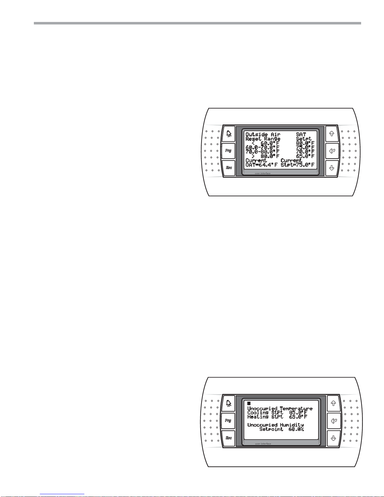
• Outside Air Reset - In the Outside Air Reset
mode of operation, the supply air temperature
setpoint will be modified based upon the outside
air temperature and where it falls within four temperature ranges. When the outside air temperature is below the lower temperature range setting,
the highest SAT Setpoint will be used. When the
outside air temperature falls between the low
setting and the medium setting, the second highest SAT Setpoint will be used. When the outside
air temperature falls between the medium setting and the high setting, the second lowest SAT
Setpoint will be used. When the outside air temperature rises above the high setting, the lowest
SAT Setpoint will be used. This screen will only be
shown if the Outside Air Reset option is selected.
This screen allows the Outside Air Low, Medium
and High Setpoints as well as the four SAT
Setpoints to be modified. The range of all setpoints on this screen is 55° to 95.0°F. However, the
Outside Air Low Setting cannot be greater than
the Outside Air Medium Setting. The Outside Air
Medium Setting cannot be less than the Outside
Air Low Setting and it cannot be greater than the
Outside Air High Setting. Lastly, the Outside Air
High Setting cannot be less than the Outside Air
Medium Setting. Also, the highest SAT Setpoint
cannot be set lower than the second highest SAT
Setpoint. The second highest SAT Setpoint cannot be set higher than the highest SAT Setpoint
and lower than the second lowest SAT Setpoint.
The second lowest SAT Setpoint cannot be set
higher than the second highest SAT Setpoint and
lower than the lowest SAT Setpoint. The lowest
SAT Setpoint cannot be set higher than the second lowest SAT Setpoint. To modify the setpoints,
press the ENTER key and use the arrow keys until
the desired setting is shown. Press the ENTER key
to accept the setpoint value.
To return to the TEMPERATURE SETTINGS MENU,
press the Esc key.
Figure 23: Outside Air Reset
• Unoccupied Settings - This screen will only be
shown if the Zone Reset and the Unoccupied
Control is selected in the Factory Configuration
Screen. These setpoints will only be used in the
unoccupied mode. The range of the Cooling
Setpoint is from the current Heating Setpoint setting to 95.0°F with a default of 65.0°F. The range
of the Heating Setpoint is from 40.0°F to the current Cooling Setpoint setting with a default of
85.0°F. To modify the setpoint, press the ENTER
key and use the arrow keys until the desired setting is shown. The range of the Unoccupied
Humidity Setpoint is 20.0% to 99.9%, with a
default of 60.0%. To modify the setpoint, press
the ENTER key and use the arrow keys until the
desired setting is shown. Press the ENTER key to
accept the setpoint value.
To return to the TEMPERATURE SETTINGS MENU,
press the Esc key.
Figure 24: Unoccupied Settings
climatemaster.com
13
CLIMATEMASTER WATER-SOURCE HEAT PUMPS
DOAS CM3500 Controller
Rev.:31 July, 2013
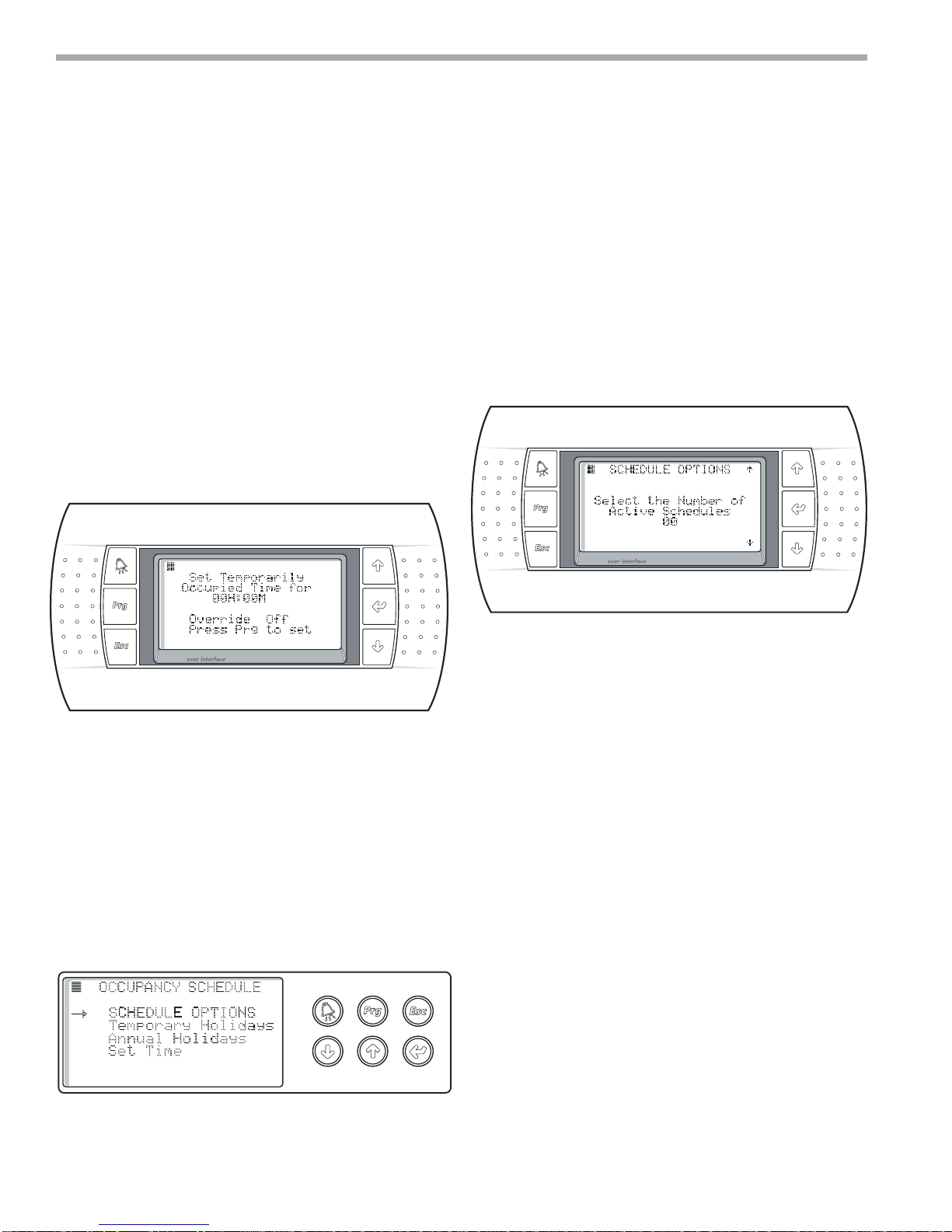
• Temporary Occupancy
This screen allows the unit to be set to the occupied
mode for a preset amount of time. Press the ENTER
key and enter the hours you would like the unit to be
temporarily in the occupied mode. Press the ENTER
key again and enter the minutes you would like the
unit to be temporarily in the occupied mode. Press the
ENTER key again and the cursor will begin blinking
over the “Press Prg to set” message. Pressing the Prg
key will override the schedule and allow the unit to be
temporarily occupied. The screen will now show
“Override On.” To clear this occupied override, set the
hours and minutes to zero and press the Prg key. The
screen will now show “Override Off.”
Figure 25: Temporary Occupancy Settings
• Schedule Options - This screen sets the number
of active occupancy schedules. Setting at least
one active schedule allows the occupancy schedule timing to be set from the Current Schedule
Screen. If the number of active schedules is left at
zero, no occupancy scheduling will be active.
To return to the OCCUPANCY SCHEDULE
MENU, press the Esc key.
Figure 27: Schedule Options
• Occupancy Schedule
Select the SCHEDULE SETUP from the MAIN MENU
to show the OCCUPANCYSCHEDULE MENU. From
this menu you can access and adjust the Schedule
Options, Temporary Holidays, Annual Holidays and
Time settings.
To return to the MAIN MENU, press the Esc key.
Figure 26: Occupancy Schedule
• Current Schedule - The bottom of this screen
allows you to set the occupancy timing for the
selected day of the week (DOW). Select the
schedule to modify the start time and stop
time. This is the time span that the unit will be
in the occupied mode. All times are set in the
24 hour format. As the DOW is selected, the
UP and DOWN keys allow for Monday, Tuesday,
Wednesday, Thursday, Friday, Saturday, Sunday
and any holiday to be occupied during that time.
Up to 10 schedules can be active at any time.
These allow for different start and stop times
on various days of the week, weekends or programmed holidays.
To return to the OCCUPANCY SCHEDULE MENU,
press the Esc key.
14
ClimateMaster Water-Source Heat Pumps

THE SMART SOLUTION FOR ENERGY EFFICIENCY
DOAS CM3500 Controller
Rev.:31 July, 2013
Figure 28: Schedule Options (Current Schedule)
• Temporary Holidays - The Temporary Holiday set-
tings are for holidays that change dates from year
to year, such as Memorial Day or Thanksgiving. Up
to 10 different temporary holidays can be set from
this screen. Select the number to assign to the
Annual Holiday and then select the Start Date and
the End Date for that holiday.
To return to the OCCUPANCY SCHEDULE MENU,
press the Esc key.
Figure 30: Schedule Options (Annual Holidays)
• Set Time - This screen sets the time, date and
day of week. To modify these settings, press the
ENTER key until the cursor is over the appropriate item and use the arrow keys until the desired
setting is shown. All times are set in the 24 hour
format. Pressing the ENTER key will step to the
next item. If any item was modified, the message
“Enter to Set” will be shown. Press the ENTER key
to accept the time an date values.
To return to the OCCUPANCY SCHEDULE MENU,
press the Esc key.
Figure 31: Set Time
Figure 29: Schedule Options (Temporary Holidays)
• Annual Holidays - The Annual Holiday settings
are for holidays with dates that remain constant
year to year, such as New Years Day and the 4th of
July. Up to 10 different annual holidays can be set
from this screen. Select the number to assign to
the Annual Holiday and then select the Start Date
and the End Date for that holiday.
To return to the OCCUPANCY SCHEDULE MENU,
press the Esc key.
climatemaster.com
15
 Loading...