

ClimateMaster Console CCE Series Installation & Operation Manual
Model Decoder 2
General Information 3
Inspection 3
Introduction 3
Storage 3
Unit Protection 3
Pre-Installation 3
Chassis Dimensions 5
Installation 6
Supply and Return Hoses 6
Installation of Supply and Return Piping 7
Condensate Piping 7
Electrical Wiring 8
Optional Wall Mounted Thermostat 8
Start-Up Preparation 10
System Checkout 10
Unit Start-Up 11
Maintenance 13
Physical Dimensions 14
Physical Data 18
Electrical Data 18
Wiring Diagrams Matrix 19
Wiring Diagrams 20
Functional Troubleshooting 25
Troubleshooting Form 27
Warranty 28
Start-Up Log 29
Revision History 30
Console 50Hz - HfC-407C
Water-sourCe Heat PumPs
InstallatIon, oPeratIon &
m
aIntenanCe
97B0035N02
Revised: 08/13/10
Console
CCE Series
Table of Contents

C l i m a t e M a s t e r Water- So ur ce Heating and Cooling Systems
C L I M A T E M A S T E R W A T E R - S O U R C E H E A T P U M P S
C o ns ol es
R e v. : 0 8 /13/ 1 0
2
This Page Intentionally Left Blank
3
c l i m a t e m a s t e r. co m
C o ns ol es
R e v. : 0 8 /13/ 1 0
T H E S M A R T S O L U T I O N F O R E N E R G Y E F F I C I E N C Y
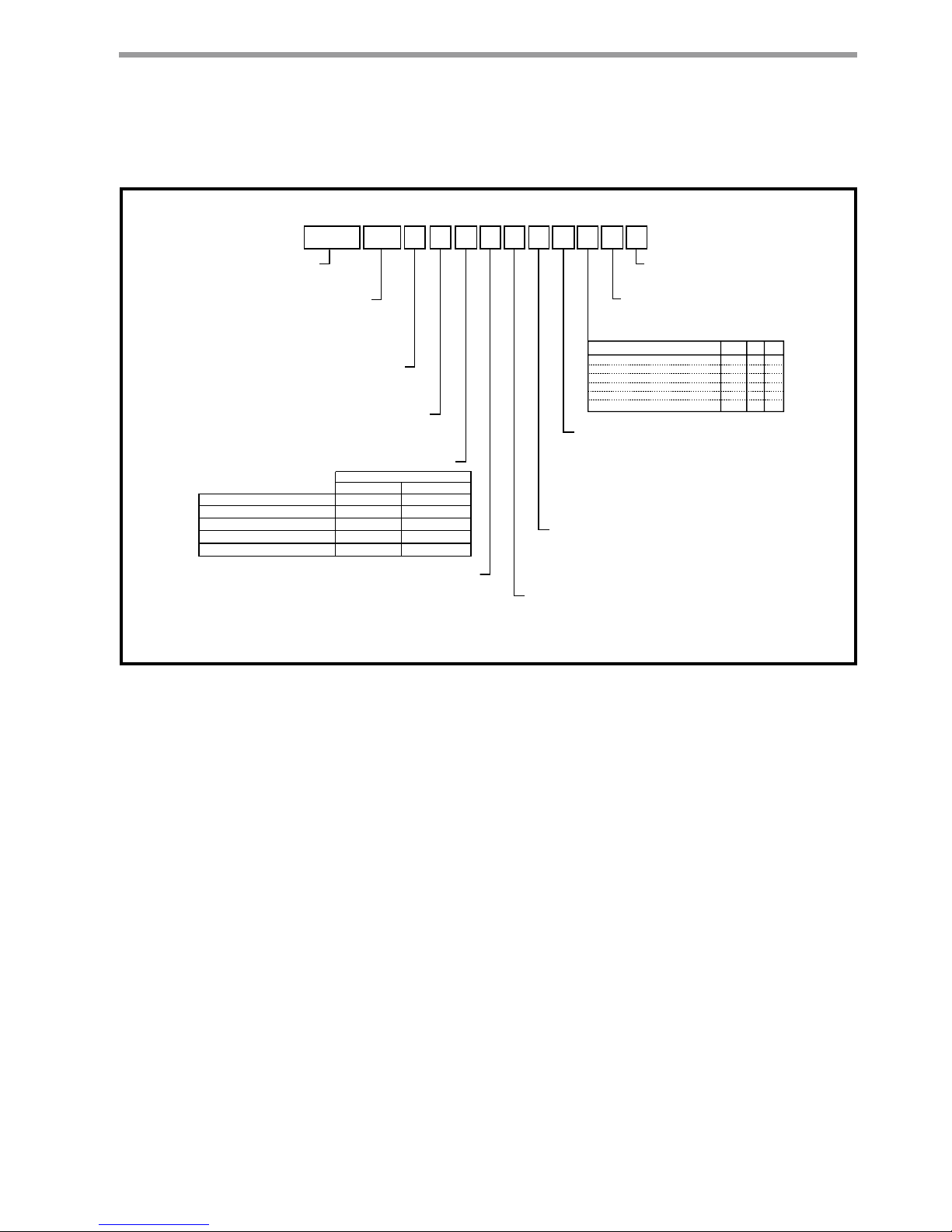
C C E AB0 7 CT S S C S R S
94 5 6
7
8 10 11 12 13 14 15
CCE = Console
Power Termination
Revision Level
Voltage
Controls
M = Bottom Return
Cabinet Insulation
Subbase
A = Copper Water Coil w/ Coated Air Coil
Heat Exchanger Options
C = Copper Water Coil
J = Cupro-nickel Water Coil w/ Coated Air Coil
N = Cupro-nickel Water Coil
R = Right Piping
Piping Connections
L = Left Piping
Standard
D = Bottom Return w/Locking Control Door
B = Front Return
D = 3” Subbase w/Motorized Damper
G = 5” Subbase
S = 3” Subbase
H = 5” Subbase w/Motorized Damper
N = None
V = Copper Water Coil w/E-Coated Air Coil & Extended Range Insulation
E = Copper Water Coil w/Extended Range Insulation
M = Cupro-nickel Water Coil w/ Coated Air Coil & Extended Range Insulation
F = Cupro-nickel Water Coil w/Extended Range Insulation
1 2 3
S = Standard
None S F M
Motorized Water Valve A G N
Autoflow (2.25 Gpm/Ton) B H P
Autoflow (3.0 Gpm/Ton) C J Q
Motorized Water Valve & Afr (2.25) D K R
Motorized Water Valve & Afr (3.0) E L T
Water Circuit Options
E = Front Return w/Locking Control Door
C = No Cabinet Chassis Only
07
09
12
15
19
Model Type
Unit Size
A = Field Connected (Hard Wire)
F = Disconnect
Sweat IPT EPT
T = 220-240/50/1 - R407C
MCO Unit Mounted T-Stat
ACO Unit Mounted T-Stat
CE Compliant
CXM DXM
E
J
F
K
Remote Mounted T-Stat
Q G
Remote Mounted T-Stat w/LON
Remote Mounted T-Stat w/MPC
H V
T U
With UltraQuiet
S = Bottom Return
L = Bottom Return w/Locking Control Door
F = Front Return
G = Front Return w/Locking Control Door
N = No Cabinet Chassis Only
Without UltraQuiet
Model Decoder
C l i m a t e M a s t e r Water- So ur ce Heating and Cooling Systems
C L I M A T E M A S T E R W A T E R - S O U R C E H E A T P U M P S
C o ns ol es
R e v. : 0 8 /13/ 1 0
4
Pre-Installation
Installation, operation and maintenance instructions
are provided with each unit. Before unit start-up, read
all manuals and become familiar with the unit and its
operation. Thoroughly check out the system before
operation. Complete the inspections and instructions
listed below to prepare a CCE unit for installation.
1. Compare the electrical data on the unit nameplate
with ordering and shipping information to verify
that the correct unit has been shipped.
2. Keep both the chassis and cabinet covered with
the shipping carton until all plastering, painting,
and finish work is complete and it is time to install
the chassis and cabinet.
3.
Verify that the refrigerant tubing is free of kinks
or dents, and that it does not touch other unit
components.
4. Inspect all electrical connections. Connections
must be clean and tight at the terminals.
To avoid equipment damage, do not use these units as
a source of heating or cooling during the construction
process. The mechanical components and lters used in
these units quickly becomes clogged with construction dirt
and debris which may cause system damage.
To avoid the release of refrigerant into the atmosphere,
the refrigerant circuit of this unit must only be serviced by
technicians which meet local, state and federal prociency
requirements.
All refrigerant discharged from this unit must be recovered
without exception. Technicians must follow industry
accepted guidelines and all local, state and federal statutes
for the recovery and disposal of refrigerants.
When a compressor is removed from this unit, system
refrigerant circuit oil will remain in the compressor. To
avoid leakage of compressor oil, the refrigerant lines of the
compressor must be sealed after it is removed.
General Information
Inspection
Upon receipt of shipment, carefully check the shipment
against the bill of lading. Verify all CCE units have been
received. Inspect each unit for damage. Be certain the
carrier makes proper notation on the delivery receipt
of all shortages and noticeable damage and he completes a Carrier Inspection Report. Concealed damage
not discovered during unloading must be reported to
the carrier within fifteen (15) days of receipt of shipment. NOTE: It is the responsibility of the purchaser
to file all necessary claims with the carrier. Notify the
ClimateMaster Traffic Department within fifteen (15)
days of receipt of all damaged shipments.
Introduction
ClimateMaster Console Air Conditioner Water Source
Heat Pump units are decentralized room terminals
designed for field connection to a closed-circuit piping
loop. They are offered in capacities ranging from 2-5.6
kW cooling.
Units must be installed indoors and are typically
installed in perimeter zones, usually under windows.
Supply air is discharged directly into the conditioned
space through discharge grille located in the top of
the unit.
Storage
CAUTION: DO NOT store or install CCE units in
corrosive environments or in locations subject to
temperature or humidity extremes (e.g., attics, garages, rooftops, etc.). Corrosive conditions and high
temperature or humidity can significantly reduce
performance, reliability, and service life. Always
move units in an upright position. Tilting units on
their sides may cause equipment damage.
Upon the arrival of the equipment at the job site,
immediately store units in their shipping cartons in a
clean, dry area. Store units in an upright position at
all times. Stack units a maximum of 3 units high. Use
pallets to separate each layer of units. Do not remove
equipment from shipping cartons until equipment is
required for installation.
Unit Protection
Cover CCE units on the job site with either shipping
cartons, vinyl film, or an equivalent protective covering.
Cap the open ends of pipes stored on the job site. In
areas where painting, plastering, or the spraying of fireproof material has not been completed, all due precautions must be taken to avoid physical damage to the
units and contamination by foreign material. Physical
damage and contamination may prevent proper startup and may result in costly equipment clean-up.
Examine all pipes, fittings, and valves before installing
the system components. Remove any dirt found on
these components.
� WARNING! �
� WARNING! �
WARNING! The installation of water source heat pumps
and all associated components, parts, and accessories
which make up the installation shall be in accordance
with the regulations of ALL authorities having jurisdiction
and MUST conform to all applicable codes. It is the
responsibility of the installing contractor to determine and
comply with ALL applicable codes and regulations.
5
c l i m a t e m a s t e r. co m
C o ns ol es
R e v. : 0 8 /13/ 1 0
T H E S M A R T S O L U T I O N F O R E N E R G Y E F F I C I E N C Y
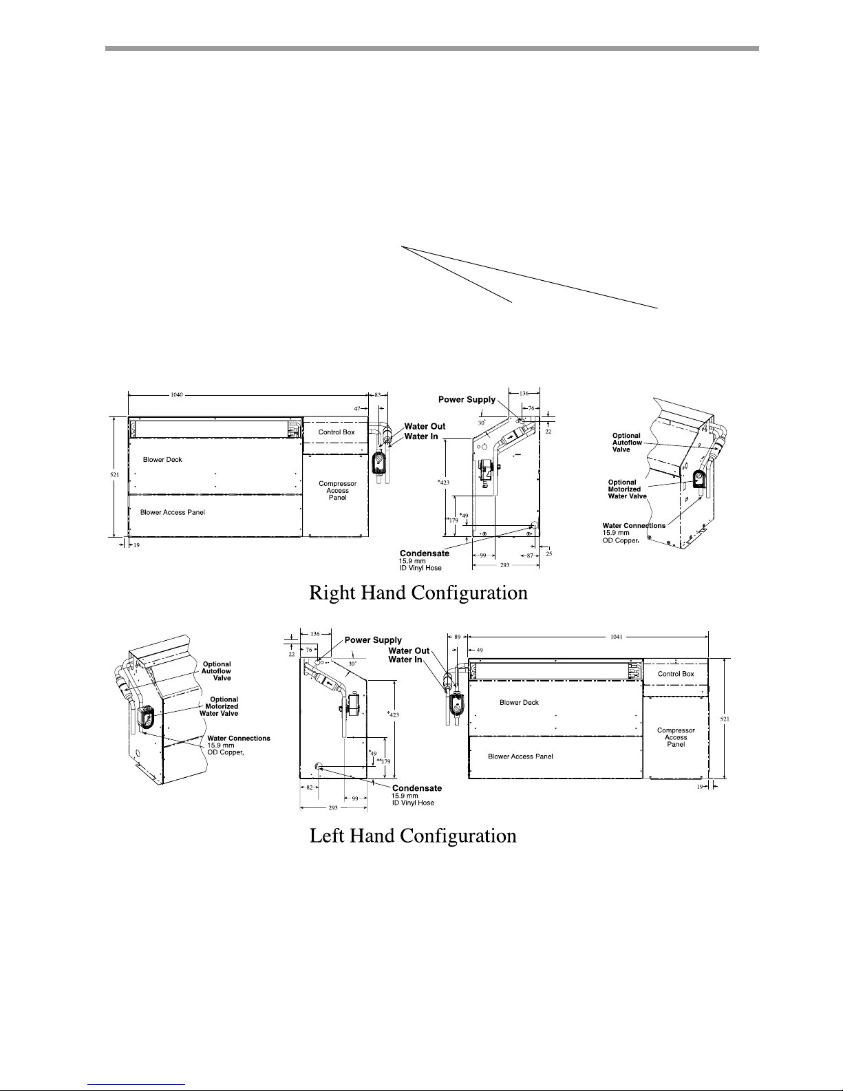
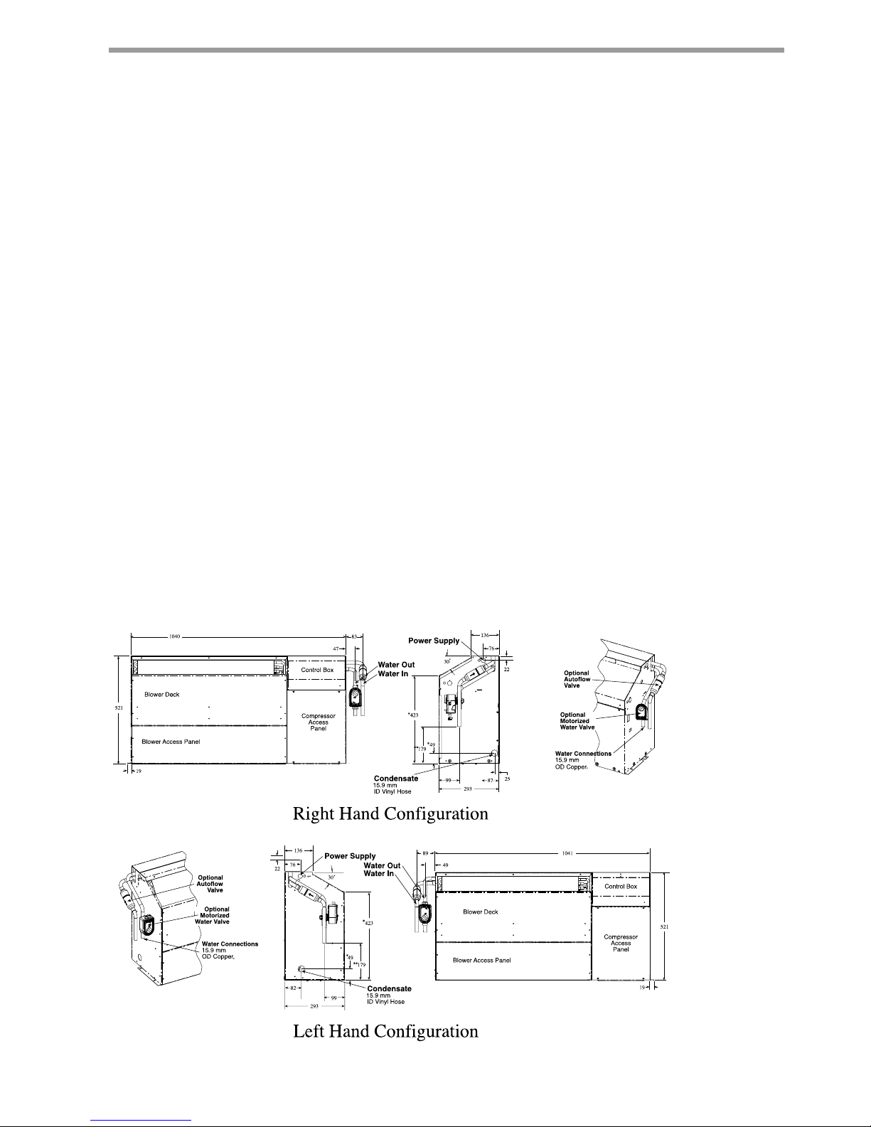
Chassis Dimensions
Figure 1a : Remove 4 shipping
bolts on compressor isolation plate.
(Not all models)
1/2” FPT or
1/2” MPT
1/2” FPT or
1/2” MPT
Notes:
All dimensions are in mm.
*For installed dimension, add to dimension shown 74mm with 3” subbase and 124mm for 5” subbase.
**Dimension reduced by fitting if selected.
Chassis Dimensions

C l i m a t e M a s t e r Water- So ur ce Heating and Cooling Systems
C L I M A T E M A S T E R W A T E R - S O U R C E H E A T P U M P S
C o ns ol es
R e v. : 0 8 /13/ 1 0
6
Installation
The installation of ConsoleWater Source Heat Pumps
and all associated components, parts and accessories
that make up the installation shall be in accordance
with the regulations of ALL Authorities having jurisdiction and MUST conform to all applicable Codes. It is
the responsibility of the Installing Contractor to determine and comply with ALL applicable Codes and
Regulations.
NOTE: An Installation Checklist is provided in this manual. Complete this checklist after all installation procedures are completed. A periodic maintenance checklist
provided in the Maintenance section outlines recommended maintenance schedules. A Start-Up Inspection
Log is also included at the end of this manual to encourage thorough unit checkout at initial start-up. These
checklists are not a substitute for the detailed information found in the Installation section of this manual.
1. CCE units are typically installed along an outside
wall of the room. Provide adequate space in front
of the unit for service and maintenance. Locate
the Console Air Conditioner so that it provides
adequate air circulation throughout the room.
2. Unpack the CCE Unit from the shipping carton.
Remove the front cabinet by lifting up and away
from the backplate. Protect the cabinet from
damage during installation by returning it to its
original vinyl pack until required.
3. Remove compressor isolation plate shipping
screws (4) as shown in Figure 1a.
4. Using a carpenter's square and a level, ensure the
unit is level. Shim the unit if necessary to assure
proper installation.
CAUTION: Poor or inadequate installation may
result in noisy unit operation or unattractive installa-
tion.
5. Select the proper fasteners to connect the
backplate securely to the wall.
6. Fasten the backplate onto the wall through the
screw holes located in the back flange. Secure the
subbase in place.
7. Make all necessary electrical connections as
described in the Electrical Wiring section of this
manual. Consult the wiring diagram to ensure
proper hook-up.
8. Connect the final piping as described in the
Supply and Return Piping and Condensate
Piping section of the manual. Install shut-off
valves, piping and/or hoses and other accessories
as specified.
9. Before making the final water connections, flush
the system as described in the Start Up section
of this manual. After flushing the system, connect
piping and hoses to the proper supply, return and
condensate connections of the unit.
NOTE: When necessary, use adapters to
connect hoses.
10. Install any other system components as required
following manufacturer's instructions.
11. After Start-up, reinstall the front cabinet by
carefully lowering the front cabinet over the
chassis onto the backplate.
Supply and Return Hoses
Optional pressure-rated hose assemblies are available for
use with ClimateMaster CCE Units. Use the following
guidelines when installing supply and return hose
assemblies.
1. Install supply and return hoses fitted with swiveljoint fittings at one end to prevent the hose from
twisting.
2. Use male adapters to secure the hose assembly to
the unit and the riser.
3. Do not allow the hose to twist during installation.
Twisting may damage the hose wall or the rubber
compound. (Not all models)
4. Use pipe joint compound sparingly on the male
pipe threads of the fitting adapters.
5. Prevent sealant from reaching the flared surfaces
of the joint.
6. Do not use pipe joint compound when teflon
thread tape is pre-applied to hose assemblies or
when flared-end connections are used.
7. Maximum torque which may be applied to brass
fittings is 30 ft-lbs. When a torque wrench is not
used, tighten brass fittings finger-tight plus one
quarter turn.
8. Tighten steel fittings as necessary.
9. Shut-off/balancing valves, flow indicators, and
drain tees in the supply runout and return at each
floor aid in loop balancing and servicing.
CAUTION: Loop Fluids should be of good
quality with no more than 0.50 ppm of
chlorides w/ Cu (125 ppm w/ CuNi) to prevent
corrosion and should also be filtered to a
maximum 800 micron particle size to prevent
erosion of the heat exchangers.
Supply and Return Piping
System piping MUST comply with all applicable codes.
1. Install a drain valve at the base of each supply and
return riser to enable system flushing at start-up
and during routine servicing.
2. Install shut-off/balancing valves and unions at each
unit to allow unit removal for servicing.
NOTE: If flex hoses are used, unions are not necessary.
3. Install strainers at the inlet of each system
circulating pump.
7
c l i m a t e m a s t e r. co m
C o ns ol es
R e v. : 0 8 /13/ 1 0
T H E S M A R T S O L U T I O N F O R E N E R G Y E F F I C I E N C Y
Installation
NOTE: If loop temperatures are expected below the ambient dew point, the optional internal insulation package
must be ordered. Insulation must also be installed on
loop water piping on those sections which run through
unheated areas or are located outside the building.
Condensate Piping
Unit is supplied with condensate drain hose, 15.9mm
I.D. flexible plastic nonpressure-rated, protruding from
piping side of unit. Connect this hose to building drain.
Avoid making kinks in hose to ensure an unobstructed
flow of condensate from the unit to the drain. DO NOT
twist, pull hose out, or push excess hose into unit. If
hose will not connect to your building drain several
options include, relocate end of building drain, add to
or cut hose, use hard plastic or copper elbow fittings
for tight radii (put inside hose). Keep hose positioned
within or over subbase area so hose does not interfer
with front cabinet. Cabinet should not push or reroute
hose. Clamp all joints watertight. Check
for leaks.
Internally the drain hose is clamped to drain pan and
pitched correctly. Horizontal runs of condensate hose
should be pitched downward 6mm (1/4 inch) minimum
for every 300MM of hose. Avoid low points and unpitch-
ing because dirt collects in these areas and may cause
blockage. If blocked the condensate level in
drain pan increases, when level gets too high, CCE unit
has sensor switch that will shut unit off, overflow may
still occur.
Building drain connection if parallel with floor the
height can be up to 38mm above subbase for proper
pitch and correct drainage, up to 130mm above is
allowable but drainage will be slower. When 65 to
130mm above the hose inside unit will act as a trap.
Heights more than 130mm above subbase are NOT
allowable (condensate overflow may occur). Check if
your unit has a disconnect box option, this limits building drain locations. See unit Configuration pages.
Field installation of a trap or vent is not required unless
specified by local codes. CCE units are designed
in a blow-through configuration. The condensate
drain pan is located on the outlet side of the blower
so that the pressure in the drain pan is higher than
atmosphere.
When drain connection is completed check for proper
drainage and leaks. Correct if necessary.
If trap is used, check and clean often. See
Maintenance Instructions.
1/2” FPT or
1/2” MPT
1/2” FPT or
1/2” MPT
Notes:
All dimensions are in mm.
*For installed dimension, add to dimension shown 74mm with 3” subbase and 124mm for 5” subbase.
Figure 1 Water Connection details
C l i m a t e M a s t e r Water- So ur ce Heating and Cooling Systems
C L I M A T E M A S T E R W A T E R - S O U R C E H E A T P U M P S
C o ns ol es
R e v. : 0 8 /13/ 1 0
8
CAUTION: Use only copper conductors for field
installed electrical wiring. Unit terminals are not
designed to accept other types of conductors.
All field installed wiring, including the electrical ground,
MUST comply with the National Electrical Code as
well as applicable local codes. In addition, all field low
voltage wiring must conform to the Class II temperature
limitations described in the NEC.
Consult the unit wiring diagram located on the inside of
the compressor access panel to ensure proper electrical
hookup. The installing (or electrical) contractor must
make the field connections shown in Figure 1 when
using field supplied disconnect.
Units have dual voltage (220-240V) control transformer.
The units are shipped for 240V operation. Modify the
transformer connection when the actual power supply
is 220 volts. Refer to the unit wiring diagram for details
of this procedure.
Make all final electrical connections with a length
of flexible conduit to minimize vibration and sound
transmission to the building.
Optional Wall-Mounted Thermostat
CCE WSHP units are built with standard internal
thermostats in either manual changeover (MCO)
or automatic changeover (ACO) configuration. No
external, field-installed low-voltage wiring is required.
When desired, the unit can be furnished with a 24-volt
control circuit which is field-wired to a ClimateMastersupplied accessory remote thermostat.
Zone integrity must be maintained to efficiently control
units or groups of units. Unless zones of control are
considered and accounted for, adjacent units may
operate in heating and cooling modes simultaneously.
Low-voltage wiring between the unit and the wall
thermostat must comply with all applicable electrical
codes (i.e., NEC and local codes), and be completed
before the unit is installed.
Table 2 lists recommended wire sizes and lengths
to install the thermostat. The total resistance of
low-voltage wiring must not exceed 1 ohm. Any
resistance in excess of 1 ohm may cause the control to
malfunction because of high voltage drop.
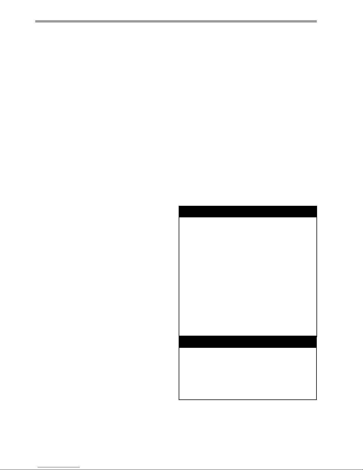
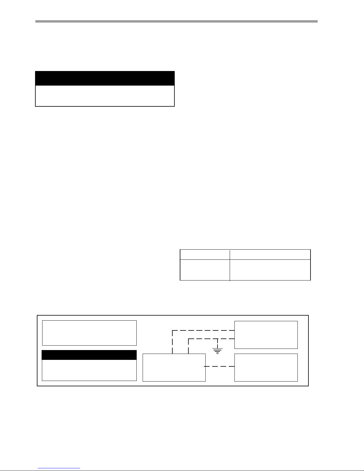
Field Supplied
Disconnect Switch
Heat Pump
A
Room Thermostat
B
A= Two power wires on single-phase units: three power wires on three-phase units. B= 1 heat /1 cool /
manual or Auto Change-over remote 24V thermostat. Note: All customer-supplied wiring to be copper
only and must conform to NEC and local electrical codes. Wiring shown with dashed lines must be field-
supplied and field-installed. "B" only required with systems employing remote mounted thermostats.
DISCONNECT ELECTRICAL POWER
SOURCE TO PREVENT INJURY OR DEATH
FROM ELECTRICAL SHOCK.
CAUTION: USE COPPER
CONDUCTORS ONLY TO PREVENT
EQUIPMENT DAMAGE.
Figure 1 Typical Field Installed Wiring
WIRE SIZE MAX. WIRE LENGTH*
18-Gauge 23 m
16-Gauge 38 m
14-Gauge 62 m
*Length = Physical distance from thermostat to unit.
Table 2 - Recommended Thermostat Wire Sizes
Electrical Wiring
To avoid possible injury or death due to electrical shock,
open the power supply disconnect switch and secure it in
an open position during installation.
� WARNING! �
� WARNING! �
9
c l i m a t e m a s t e r. co m
C o ns ol es
R e v. : 0 8 /13/ 1 0
T H E S M A R T S O L U T I O N F O R E N E R G Y E F F I C I E N C Y
System Cleaning and Flushing
Cleaning and flushing the unit and system is the single
most important step to ensure proper start-up and
continued efficient operation of the system. Follow
the instructions below to properly clean and flush the
system:
DO NOT FLUSH SYSTEM THROUGH THE UNIT!
To prevent injury or death due to electrical shock or
contact with moving parts, open unit disconnect before
servicing unit.
1. Verify that electrical power to the unit is
disconnected and that the circulation pump is
de-energized.
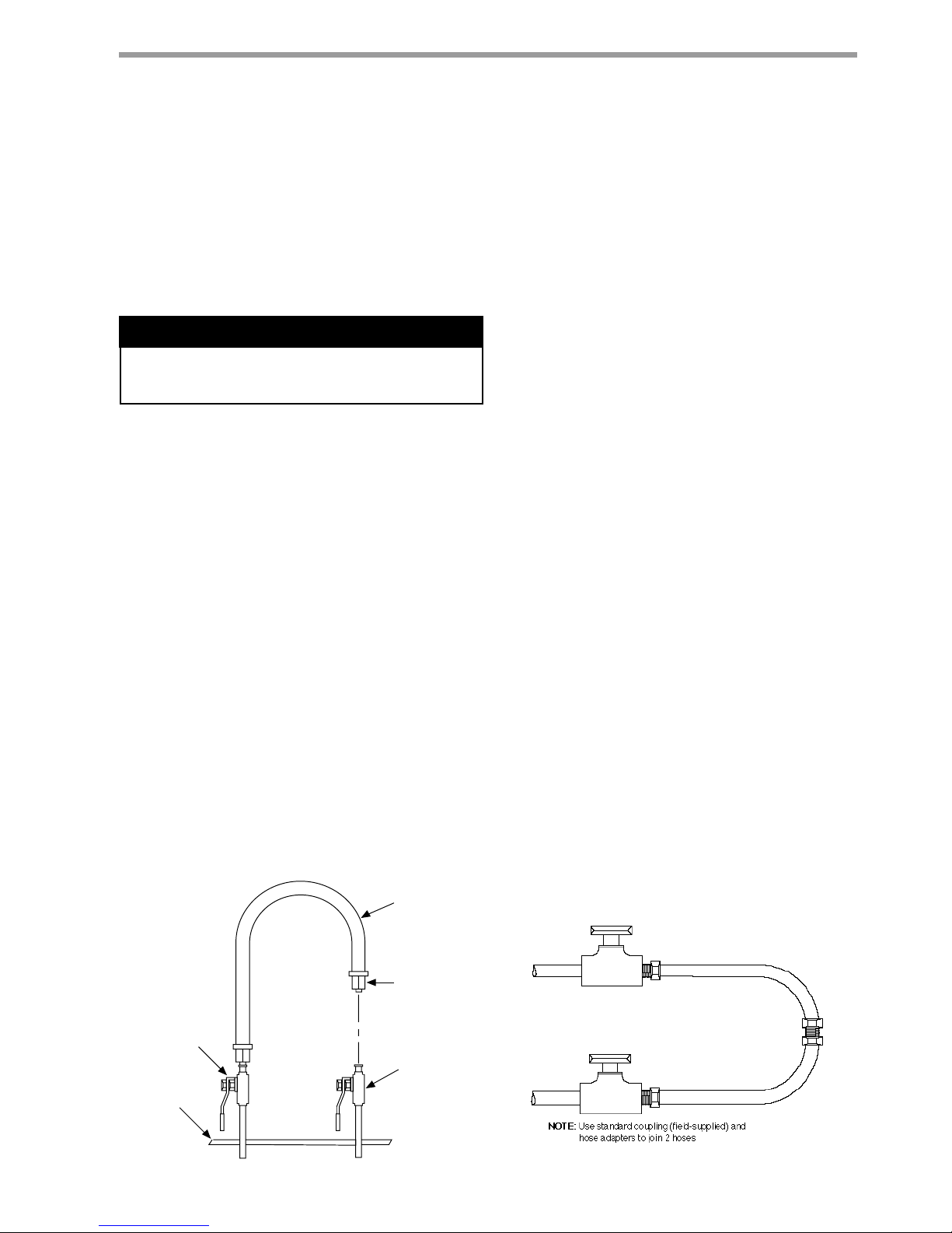
2. Connect the supply hose directly to the return
riser valve. Use a single length of flexible hose as
illustrated in Figure 2 below.
NOTE: When one hose is too short to make the
connection without exceeding the minimum bend
radius of the hose, substitute two length of flexible
hose joined together with a field-supplied, standard
MPT coupling. Use the adapter provided with the
hose kit as shown in Figure 3.
3. Fill the system with water, leaving the air vents
open. Bleed all air from the system but do not
allow the system to over flow. Check the system
for leaks and make any required repairs. Adjust
the water and air level in the expansion tank.
4. With strainers in place, start the pumps.
Systematically check each vent to ensure that all
of the air is bled from the system.
5. Verify that make-up water is available and
adjusted to properly replace any space remaining
when all air is evacuated. Pressure test and inspect
the system for leaks and make any additional
repairs required.
Start-Up Preparation
6.
Open the drain at the lowest point in the system.
Verify that make-up water replacement rate equals
rate of bleed. Continue to bleed the system until
the water appears clean or for at least three hours
whichever is longer.
7. Completely drain the system.
8. Refill the system with clean, chemically treated
water. Since water varies for each locality, contact
a local water treatment company for the correct
cleaning chemicals to use in your area.
CAUTION: To avoid possible damage to piping
systems constructed of plastic piping, DO NOT
allow loop temperature to exceed 43 °C.
9. Set the boiler to raise the loop temperature to
approximately 29.4°C. Circulate the solution for
a minimum of 8 to 24 hours. At the end of this
period, shut off the circulating pump and drain the
solution. Repeat system cleaning if necessary.
10. When the cleaning process is complete, remove
the short-circuit hoses. Connect the hoses to the
proper supply and return connections to the unit.
Refill the system and bleed off all air.
11. Test the system pH with litmus paper. The system
water should be slight alkaline (pH 7.5 to 8.5). Add
chemicals as appropriate to maintain acidity levels.
CAUTION: DO NOT use "Stop-Leak" or any similar
chemical agent in this system. Addition of these
chemicals to the loop water will foul the system and
will inhibit unit operation.
12. When the system is successfully cleaned, flushed,
refilled and bled, check the main system panels,
safety cutouts and alarms. Set controls to properly
maintain loop temperature.
Figure 3
Figure 2
� WARNING! �
 Loading...