

ClimateMaster CS Series, CL Series Installation & Operation Manual
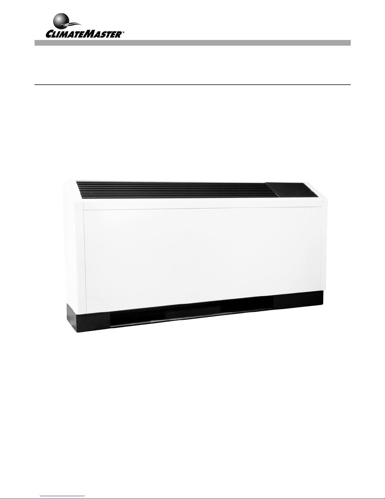
CS/CL Series
Console Air Conditioners
Water Source Heat Pumps
Installation, Operation, &
Maintenance Instructions

TABLE OF CONTENTS
Page
General Information 3
Inspection 3
Introduction 3
Storage 3
Unit Protection 3
Pre-Installation 4
Installation 4
Supply and Return Hoses 4
Installation of Supply and Return Piping 5
Condensate Piping 5
Electrical Wiring 5
Optional Night Setback Control 5
Optional CMC-2000 Controller 6
Optional Wall Mounted Thermostat 6
Start-Up Preperation 7
System Checkout 8
Unit Start-Up 9
Maintenance 11
Warranty 13
Page 2
GENERAL INFORMATION
Inspection
Upon receipt of shipment, carefully check the shipment
against the bill of lading. Verify all CS/CL units have
been received. Inspect each unit for damage. Be certain
the carrier makes proper notation on the delivery receipt
of all shortages and noticeable damage and he completes
a Carrier Inspection Report. Concealed damage not
discovered during unloading must be reported to the
carrier within fifteen (15) days of receipt of shipment.
NOTE: It is the responsibility of the purchaser to file
all necessary claims with the carrier. Notify the
ClimateMaster Traffic Department within fifteen (15)
days of receipt of all damaged shipments.
Introduction
ClimateMaster Console Air Conditioner Water Source
Heat Pump units are decentralized room terminals
designed for field connection to a closed-circuit piping
loop. They are offered in capacities ranging from 6,800
to 17,600 BTUH cooling and 8,500 to 21,000 BTUH
heating.
Units are typically installed in perimeter zones, usually
under windows. Supply air is discharged directly into the
conditioned space through discharge grills located in the
top of the unit.
Storage
contamination by foreign material. Physical damage and
contamination may prevent proper start-up and may
result in costly equipment clean-up.
Examine all pipes, fittings, and valves before installing
the system components. Remove any dirt found on these
components.
Pre-Installation
Installation, operation and maintenance instructions are
provided with each unit. Before unit start-up, read all
manuals and become familiar with the unit and its
operation. Thoroughly check out the system before
operation. Complete the inspections and instructions
listed below to prepare a CS/CL unit for installation.
1. Compare the electrical data on the unit nameplate
with ordering and shipping information to verify that
the correct unit has been shipped.
2. Keep both the chassis and cabinet covered with the
shipping carton until all plastering, painting, and
finish work is complete and it is time to install the
chassis and cabinet.
3. Verify that the refrigerant tubing is free of kinks or
dents, and that it does not touch other unit components.
4. Inspect all electrical connections. Connections must
be clean and tight at the terminals.
CAUTION: DO NOT store or install CS/CL units in
corrosive environments or in locations subject to
temperature or humidity extremes (e.g., attics,
garages, rooftops, etc.). Corrosive conditions and high
temperature or humidity can significantly reduce
performance, reliability, and service life. Always
move units in an upright position. Tilting units on
their sides may cause equipment damage.
Upon the arrival of the equipment at the job site, immediately store units in their shipping cartons in a clean, dry
area. Store units in an upright position at all times.
Stack units a maximum of 3 units high. Use pallets to
separate each layer of units. Do not remove equipment
from shipping cartons until equipment is required for
installation.
Unit Protection
Cover CS/CL units on the job site with either shipping
cartons, vinyl film, or an equivalent protective covering.
Cap the open ends of pipes stored on the job site. In areas
where painting, plastering, or the spraying of fireproof
material has not been completed, all due precautions
must be taken to avoid physical damage to the units and
To avoid equipment damage, do not use these units as
a source of heating or cooling during the construction
process. The mechanical components and filters used
in these units quickly becomes clogged with
construction dirt and debris which may cause system
damage.
To avoid the release of refrigerant into the
atmosphere, the refrigerant circuit of this unit must
only be serviced by technicians which meet local, state
and federal proficiency requirements.
All refrigerant discharged from this unit must be
recovered without exception. Technicians must follow
industry accepted guidelines and all local, state and
federal statutes for the recovery and disposal of
refrigerants.
When a compressor is removed from this unit, system
refrigerant circuit oil will remain in the compressor.
To avoid leakage of compressor oil, the refrigerant
lines of the compressor must be sealed after it is
removed.
Page 3

INSTALLATION
The installation of ConsoleWater Source Heat Pumps and
all associated components, parts and accessories that
make up the installation shall be in accordance with the
regulations of ALL Authorities having jurisdiction and
MUST conform to all applicable Codes. It is the
responsibility of the Installing Contractor to determine
and comply with ALL applicable Codes and Regulations.
NOTE: An Installation Checklist is provided at the
end of this manual. Complete this checklist after all
installation procedures are completed. A periodic
maintenance checklist provided in the Maintenance
section outlines recommended maintenance schedules.
A Start-Up Inspection Log is also included at the end
of this manual to encourage thorough unit checkout
at initial start-up. These checklists are not a substitute
for the detailed information found in the Installation
section of this manual.
1. CS/CL units are typically installed along an outside
wall of the room. Provide adequate space in front of
the unit for service and maintenance. Locate the
Console Air Conditioner so that it provides adequate
air circulation throughout the room.
2. Unpack the CS/CL Unit from the shipping carton.
Remove the front cabinet by lifting up and away
from the backplate. Protect the cabinet from damage
during installation by returning it to its original vinyl
pack until required.
3. Using a carpenter's square and a level, ensure the
unit is level. Shim the unit if necessary to assure
proper installation.
CAUTION: Poor or inadequate installation may
result in noisy unit operation or unattractive
installation.
4. Select the proper fasteners to connect the backplate
securely to the wall.
5. Fasten the backplate onto the wall through the screw
holes located in the back flange. Secure the subbase
in place.
6. Make all necessary electrical connections as described in the Electrical Wiring section of this
manual. Consult the wiring diagram to ensure proper
hook-up.
CAUTION: RH Units - Entering Water is upper pipe.
LH Units - Entering Water is lower pipe.
8. Before making the final water connections, flush the
system as described in the Start Up section of this
manual. After flushing the system, connect piping
and hoses to the proper supply, return and condensate connections of the unit.
NOTE: When necessary, use adapters to connect
hoses.
9. Reinstall the front cabinet by carefully lowering the
front cabinet over the chassis onto the backplate.
10. Install any other system components as required
following manufacturer's instructions.
Supply and Return Hoses
Optional pressure-rated hose assemblies are available for
use with ClimateMaster CS/CL Units. Use the following
guidelines when installing supply and return hose
assemblies.
1. Install supply and return hoses fitted with swiveljoint fittings at one end to prevent the hose from
twisting.
2. Use male adapters to secure the hose assembly to the
unit and the riser.
3. Do not allow the hose to twist during installation.
Twisting may damage the hose wall or the rubber
compound.
4. Use pipe joint compound sparingly on the male pipe
threads of the fitting adapters.
5. Prevent sealant from reaching the flared surfaces of
the joint.
6. Do not use pipe joint compound when teflon thread
tape is pre-applied to hose assemblies or when
flared-end connections are used.
7. Maximum torque which may be applied to brass
fittings is 30 foot pounds. When a torque wrench is
not used, tighten brass fittings finger-tight plus one
quarter turn.
8. Tighten steel fittings as necessary.
9. Shut-off/balancing valves, flow indicators, and drain
tees in the supply runout and return at each floor aid
in loop balancing and servicing.
7. Connect the final piping as described in the Supply and
Return Piping and Condensate Piping section of the
manual. Install shut-off valves, piping and/or hoses
and other accessories as specified.
Page 4
Supply and Return Piping
System piping MUST comply with all applicable codes.
1. Install a drain valve at the base of each supply and
return riser to enable system flushing at start-up and
during routine servicing.
2. Install shut-off/balancing valves and unions at each
unit to allow unit removal for servicing.
NOTE: If flex hoses are used, unions are not
necessary.
3. Install strainers at the inlet of each system circulating
pump.
NOTE: Since loop temperature is normally between
60° and 90° F, pipe sweating and heat loss does not
occur at normal ambient conditions. Insulation must
be installed on loop water piping on those sections
which run through unheated areas or are located
outside the building.
Condensate Piping
Connect the unit condensate drain to the building
condensate drain with a flexible, nonpressure-rated 5/8
inch I.D. plastic hose. Avoid kinks in this hose to ensure
an unobstructed flow of condensate from the unit to the
drain.
The horizontal run of the condensate hose is usually too
short to pose any drainage problems however, the
horizontal run of condensate line ought to be pitched at
least one inch for every 10 feet of run in the direction of
flow. Avoid low points and unpitched piping since dirt
collects in these areas and may cause stoppage and
overflow.
Field installation of a trap or vent is not required unless
specified by local codes. CS/CL units are designed in a
blow-through configuration. The condensate drain pan is
located on the outlet side of the blower so that the
pressure in the drain pan is higher than the atmosphere.
All field installed wiring, including the electrical ground,
MUST comply with the National Electrical Code as well
as applicable local codes. In addition, all field wiring
must conform to the Class II temperature limitations
described in the NEC.
Consult the unit wiring diagram located on the inside of
the compressor access panel to ensure proper electrical
hookup. The installing (or electrical) contractor must
make the field connections shown in Figure 1 when using
field supplied disconnect.
Modify the transformer connection for units rated
208-230 volts with a 24-volt transformer when the actual
power supply is 230 volts. Refer to the unit wiring
diagram for details of this procedure.
Make all final electrical connections with a length of
flexible conduit to minimize vibration and sound
transmission to the building.
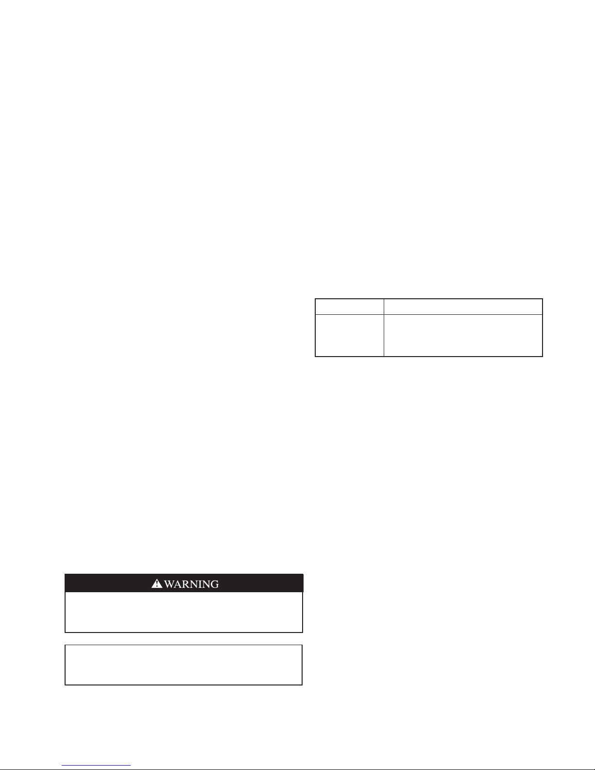
Table 1 Operating Voltages
Volts/Hz/Phase Operating Range
115/60/1
208/230/60/1
265/60/1
104 Volts min - 127 Volts max
197 Volts min - 250 Volts max
238 Volts min - 292 Volts max
Optional Night Setback Control
An optional hard-wired night setback system (NSB) is
available. This system consists of a central (or zone)
night setback control panel and an individual NSB relay
at each heat pump.
Refer to unit wiring diagrams for specific night setback
options and correct method of wiring.
Electrical Wiring
To avoid possible injury or death due to electrical
shock, open the power supply disconnect switch and
secure it in an open position during installation.
CAUTION: Use only copper conductors for field
installed electrical wiring. Unit terminals are not
designed to accept other types of conductors.
Page 5
 Loading...