

ClimateMaster ATC32U02 iGate Installation Manual

ATC32U02 iGate™ Communicating,
Programmable Thermostat
Installation Manual
97B0055N03
Rev.: 2/24/14
Caution:
These instructions are intended to be used by the installer or service personnel. End users are NOT advised to change or
modify any of these settings. Doing so may cause the equipment to stop working properly and/or may void the warranty on
both the thermostat and the equipment.
Table of Contents
Section Title Page
Safety/Installation Considerations 3
1.0 User Menu Settings 4
2.0 Installer Menu Settings 6
2.1 Installer Menu Settings Access 6
2.2 Thermostat Confi guration 6
3.0 System Confi guration 7
3.1 Airfl ow Selection 7
3.2 Option Selection 7
3.3 Unit Confi guration 8
3.4 Pump Confi guration 8
3.5 Valve Confi guration 9
3.6 Multi-Unit Confi guration 9
4.0 Accessory Confi guration 10
4.1 Air Filter 10
4.2 Humidifi er 10
4.3 UV Lamp 10
Section Title Page
4.4 Air Cleaner 10
5.0 Input Dealer Information 10
6.0 Humidity Confi guration 1 1
7.0 Temperature Algorithm 11
8.0 Demand Reduction Confi guration 12
9.0 Service Mode 12
9.1 Manual Operation 12
9.2 Control Diagnostics 12
9.3 Dipswitch Confi guration 13
9.4 Fault History 13
9.5 Clear Fault History 14
9.6 Multi-Unit Diagnostics 14
9.7 Multi-Unit Fault Information 15
10.0 Restore Defaults 15
11.0 Revision History 16

This page was intentionally left blank.
ATC32U02 Communicating, Programmable Thermostat - IOM
Rev.: 24 Feb., 2014
ClimateMaster’s ATC32U** Communicating, Programmable
Thermostat is the perfect compliment to a ClimateMaster
Geothermal Heat Pump System and represents a signifi cant
advancement in thermostat communicating technology. For
homeowners, the ATC32U** provides highly customizable climate control features designed to maximize comfort and reduce the amount of energy consumed by the ClimateMaster
Geothermal Heat Pump System. For dealers, it represents
a signifi cant, industry leading advancement in confi guration,
monitoring and diagnostics from the thermostat. Please read
the following instructions carefully to maximize the comfort
and cost-saving potential of your ClimateMaster Geothermal
Heat Pump System.
SAFETY CONSIDERATIONS
Improper wiring or installation may damage thermostat. Wiring must conform to local and national electrical codes
WARNING!
WARNING!
power to unit. There may be more than one power
disconnect. Electrical shock can cause personal
injury or death.
INSTALLATION CONSIDERATIONS
The thermostat requires no batteries. The thermostat is not
a power stealing device and MUST have both R and C terminals connected. See Diagram 1.
Before installing thermostat, turn off all
a time. Be careful not to allow wires to fall back
into the wall.
C. As each wire is disconnected, record wire color
and terminal marking.
D. Discard or recycle old thermostat.
NOTE: Mercury is a hazardous waste and MUST be disposed of properly.
3. Separate the thermostat from base.
4. Route thermostat wires through hole in base. Level
base against wall (for aesthetic value only - thermostat need not be leveled for proper operation) and
mark wall through 2 mounting holes.
5. Drill two 3/16-in. mounting holes in wall where
marked. (Note: Mounting holes on thermostat are
designed to fi t on a horizontal J-box).
6. Secure base to wall with 2 anchors and screws
provided making sure all wires extend through hole in
base.
7. Connect wires to proper terminal of the connector
block in the thermostat.
8. Push any excess wire back into wall. Excess wire
inside the thermostat case can interfere with proper
air fl ow across the temperature sensor. Seal hole in
wall to prevent air leaks. Leaks can affect operation.
9. Install thermostat on base.
10. Turn on power to the unit.
III. WIRING DIAGRAMS
All excess wire should be pushed back into the wall as far as
possible. Excess wire inside the thermostat plastic case may
interfere with the air fl ow across the temperature sensor.
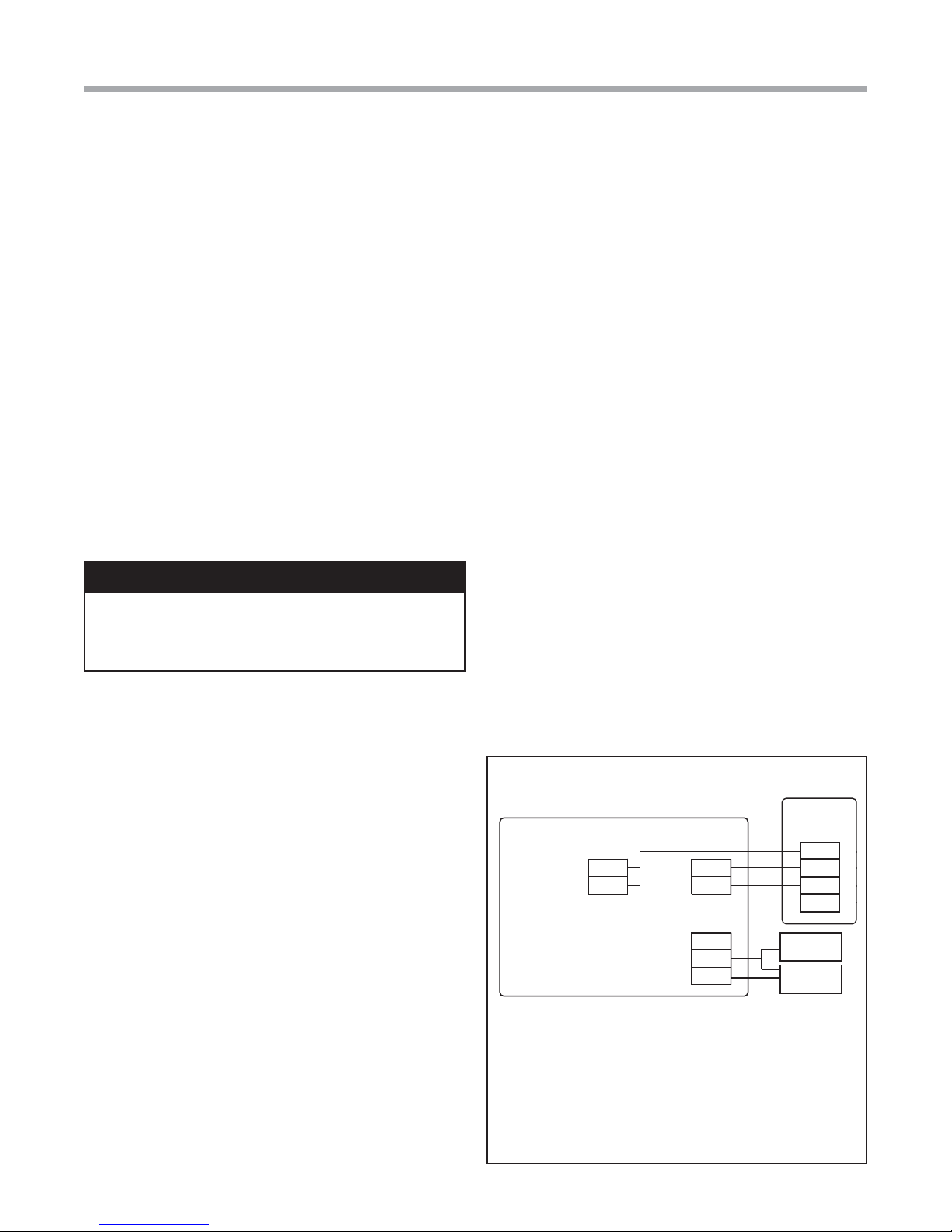
Diagram 1: Thermostat Connections
INSTALLATION
I. THERMOSTAT LOCATION
Thermostat should be mounted:
• Approximately 5 ft. (1.5m) above fl oor.
• Close to or in a frequently used room, preferably on an
inside partitioning wall.
• On a section of wall without pipes or duct work.
Thermostat should NOT be mounted:
• Close to a window, on an outside wall, or next to a
door leading to the outside.
• Exposed to direct light and heat from a lamp, sun,
fi replace, or other temperature-radiating object which
may cause a false reading.
• Close to or in direct airfl ow from supply registers.
• In areas with poor air circulation, such as behind a
door or in an alcove.
II. THERMOSTAT INSTALLATION
1. Turn off all power to unit.
2. If an existing thermostat is being replaced:
A. Remove existing thermostat from wall.
B. Disconnect wires from existing thermostat, one at
ATC32U** Thermostat
24Vac Common
24Vac Hot
Comm +
C
Comm -
R
A+
B-
OD
GND
ID
Thermostat Connections
C 24V Common for Control Circuit
R 24V Supply for Control Circuit
A+ Communications (Positive)
B – Communications (Negative)
GND Ground
OD Outdoor Temperature Sensor
ID Indoor Temperature Sensor
DXM2
Control
Gnd
A+
B-
24V
Outdoor
Sensor
(Optional)
Remote Indoor
Sensor
(Optional)
3
ATC32U02 Communicating, Programmable Thermostat - IOM
Rev.: 24 Feb., 2014
1.0 User Menu Settings
1.1 OFFSETS
If you fi nd that the temperature displayed on the
thermostat does not accurately represent the room
temperature where the thermostat is located, this
offset function compensates for the difference.
The thermostat will apply an offset between what
temperature the thermostat is measuring versus the
temperature that is displayed.
1.1.1 TEMPERATURE OFFSET
The Temperature Offset function allows for
calibration of the temperature sensor.
Adjust the Temperature Offset settings using the
up/down arrow buttons. Press the center button to
save changes.
• Indoor Temperature (default 0°F): options:
-5°F to +5°F (in 1°F increments)
• Remote Temperature (default 0°F): options:
-5°F to +5°F (in 1°F increments)
• Outdoor Temperature (default 0°F): options:
-5°F to +5°F (in 1°F increments)
• 1st Stage (default 1°F): options: 1°F to 4°F
(in 1°F increments)
• 2nd Stage (default 1°F): options: 1°F to 4°F
(in 1°F increments)
• Aux Heat (default 1°F): options: 1°F to 4°F
(in 1°F increments)
The Auto Changeover Time is the amount of time that
elapses before operation switches from heating to
cooling mode or from cooling to heating mode.
Adjust the Auto Changeover Time using the up/
down arrow buttons. Press the center button to save
changes.
• Auto Change Over Time (default 15 minutes):
options: 0 to 120 minutes (in 15 minute
increments)
1.3 DEMO MODE
Demo mode is designed to showcase heat pump
operation when the unit is connected to an above
ground water loop with the supply air being blown
directly over the water loop.
1.3.1 ENTER DEMO MODE
To enter Demo Mode, navigate to the Service
Information screen (Menu>Settings>Service
Information) then press and hold the right arrow for
5 seconds
SERVICE INFORMATION
FAULT STATUS
CLEAR FAULT HISTORY
SYSTEM STATUS
NOTE 1: The thermostat must be confi gured for
Multistage by installer to access the 2nd Stage
Differential setting. The thermostat must be
confi gured for Auxiliary Heat by installer to access
the Auxiliary Heat Differential setting.
NOTE 2: The temperature control algorithm must
be confi gured for Differential control to access the
Differential settings by installer.
1.1.2 HUMIDITY OFFSET
If you fi nd that the Humidity level displayed on
the thermostat does not accurately represent the
Humidity level of the room in which the thermostat
is located, use the Humidity Offset function to
calibrate the humidity sensor.
Adjust the Humidity Offset setting using the up/
down arrow buttons. Press the center button to
save changes.
• Indoor Humidity (default 0%): options:
-10% to +10% (in 1% increments)
1.2 AUTO CHANGEOVER TIME
When the thermostat is confi gured for AUTO mode,
the thermostat automatically selects heating or
cooling mode depending on the indoor temperature.
SELECT OPTION
PREVIOUS
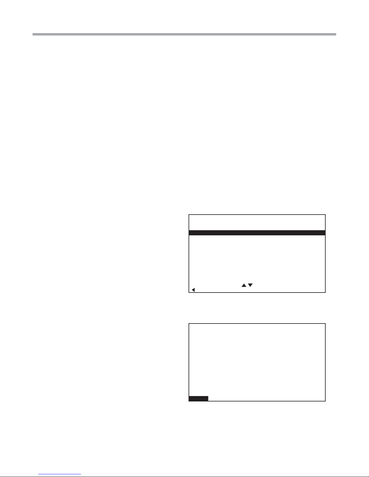
1.3.2 DEMO MODE OPERATION
Control Demo Mode operation parameters from the
Demo Operation screen shown below.
DEMO OPERATION
OUTDOOR FAN AUTO
78% HEATING
RH 36% HUMID ON
72%
AUTO
SETPOINT
HEAT 70
COOL 74
RH TEMP MODE FAN MENU
4
Geothermal Heat Pump Systems
ATC32U02 Communicating, Programmable Thermostat - IOM
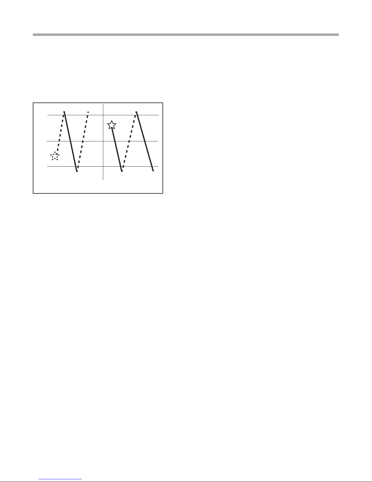
The starting mode (heating or cooling) depends
on the loop temperature at the time when Demo
Mode is entered. The unit will operate in heating or
cooling based upon the following algorithm.
Start in Cooling Mode Start in Heating Mode
90°F
70°F
50°F
Solid lines represent heating operation. Dashed lines represent
cooling operation.
Rev.: 24 Feb., 2014
1.3.3 EXITING DEMO MODE
To exit demo mode, remove power to the
thermostat.
5
 Loading...