

ClimateMaster ATA11H01 Installation Instructions Manual
Microelectronic Thermostat
INSTALLATION INSTRUCTIONS
Use form 69-0959 except use Table 2 and the hookup diagrams that follow.
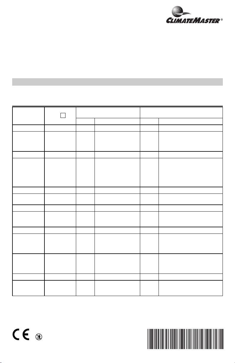
Table 2. Thermostat installer setup options.
Mode Number
(Press i key
Select
Not used 01 — — — —
Fan operation 02 01 Heat pump and electric
Not used 03 — — — —
Heating cycle
rate
Not used 05 thru 11 — — — —
Changeover
(T8501D only)
Not used 13 — — — —
Degree
temperature
display
Not used 15 thru 18 — — — —
Extended fan
operation in
a
heating
Extended fan
operation in
cooling
Not used 21 thru 23 — — — —
Outdoor
temperature
display
a
Mode 02 must be set to 01 to extend fan operation.
to change)
04 03 3 cph used for
12 00 Automatic changeover 01 Manual changeover
14 00 Temperature is
19 01 Fan operation is
20 01 Fan operation is
24 00 No outdoor temperature
Factory-Setting
Display Description Display Description
heat applications where
thermostat controls fan
operation in heat mode.
conventional systems
displayed in °F
extended 90 seconds
after the call for heat
ends.
extended 90 seconds
after the call for cool
ends
is displayed
(Press ▲ or ▼ key to change)
00 Conventional applications where
01, 06,
or 09
01 Temperature is displayed in °C
00 No extended fan operation after
00 No extended fan operation after
01 Outdoor temperature is displayed.
ATA11H01
T8501D1087
Other Choices
equipment controls fan operation
in heat mode.
01—1 cph used for radiant floor
heat, gravity systems
06—6 cph used for conventional
systems.
09—9 cph used for electric heat
systems
the call for heat ends
the call for cool ends
Needs a C7089B1000 Outdoor
Sensor to operate.
(continued)
®U.S. Registered Trademark
69-1312-1
ATA11H01
MICROELECTRONIC THERMOSTAT
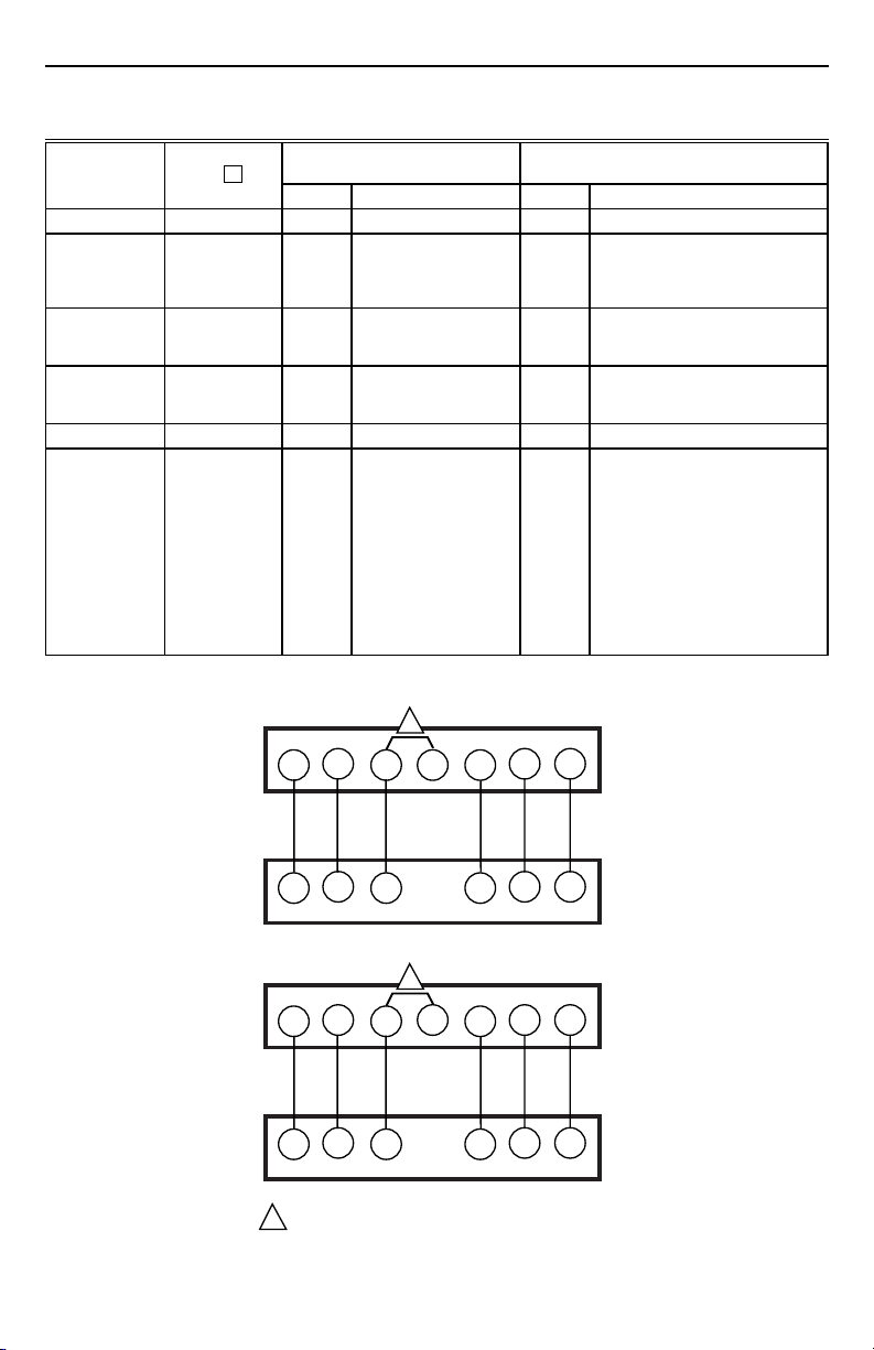
Table 2. Thermostat installer setup options (continued).
Mode Number
(Press i key
Select
to change)
Not used 25 thru 32 — — — —
Minimum off
time for the
compressor
Heating setpoint
range stop
Cooling setpoint
range stop
33 00 No minimum off time for
34 80 Heating setpoint can be
35 60 Cooling setpoint can be
Not used 36 — — — —
Temperature
display
adjustment
37 00 No difference in
Factory-Setting
(Press ▲ or ▼ key to change)
Display Description Display Description
the compressor
set no higher than 80°F
set no lower than 60°F
displayed temperature
and actual room
temperature
01, 02,
03, 04
or 05
40 thru90Number can be set anywhere
45 thru99Number can be set anywhere
c
-03 thru0301—Display adjusts to 1°F higher
Other Choices
Minimum number of minutes
(0 thru 5) the compressor will be
off between calls for the
compressor
between 40 and 90 in 1°F
increments
between 45 and 99 in 1°F
increments
than actual room temperature
02—Display adjusts to 2°F higher
than actual room temperature
03—Display adjusts to 3°F higher
than actual room temperature
-01—Display adjusts to 1°F lower
than actual room temperature
-02—Display adjusts to 2°F lower
than actual room temperature
-03—Display adjusts to 3°F lower
than actual room temperature
T8501D
R C Y
R C Y1
T8501D
R C Y
R C Y
FACTORY INSTALLED JUMPERS.
1
69-1312—1 G.H. Rev. 5-99 Printed in Taiwan R.O.C.
69-1312
1
W
DXM TERMINALS
1
W
CXM TERMINALS
2
O
O/W2
O
O
G X1
G AL1
G X1
G AL1
M14304
www.honeywell.com/yourhome
 Loading...