

ClimateMaster ACDU03 Operation Manual

ACDU03 Communicating
Service Tool
Operation Manual
97B0106N01
Rev.: 11/3/17
Caution:
These instructions are intended to be used by the installer or service personnel. End users are NOT advised to change or
modify any of these settings. Doing so may cause the equipment to stop working properly and/or may void the warranty on
both the thermostat and the equipment.
Table of Contents
Section Title Page
1.0 Connection 3
2.0 Menu Structure 4
3.0 System Confi guration 4
3.1 Airfl ow Selection 4
3.2 Option Selection 5
3.3 Unit Confi guration 5
3.4 Pump Confi guration 6
3.5 Valve Confi guration 6
3.6 Multi-Unit Confi guration 7
4.0 Service Mode 8
4.1 Manual Operation 8
4.2 Control Diagnostics 8
4.3 Dipswitch Confi guration 9
4.4 Fault History 9
4.5 Clear Fault History 11
5.0 Revision History 12

This page was intentionally left blank.
ACDU03 Communicating Service Tool
P1
Alarm
O
Y1
Y2
W
G
C
R
AL1
R
C
R
NSB
AL2
JW1
P2
P5
B-
Gnd
A+ 24V
DXM2
Board
Rev.: November 3, 2017
1.0 Connection
ClimateMaster’s Communicating Service Tool (ACDU03) allows install and service technicians to confi gure and diagnose
ClimateMaster Digital Communicating Units without installing a digital communicating thermostat.
Using the Service Tool, a technician can ELECTRONICALLY:
1. Confi gure items like: airfl ow, heat pump options and confi guration, pump or modulating valve operation, unit family, unit
size, etc.
AND
2. Diagnose the unit by operating it manually, performing control diagnostics, viewing dip switch confi gurations, or by
viewing fault history and operating conditions when a fault occurred.
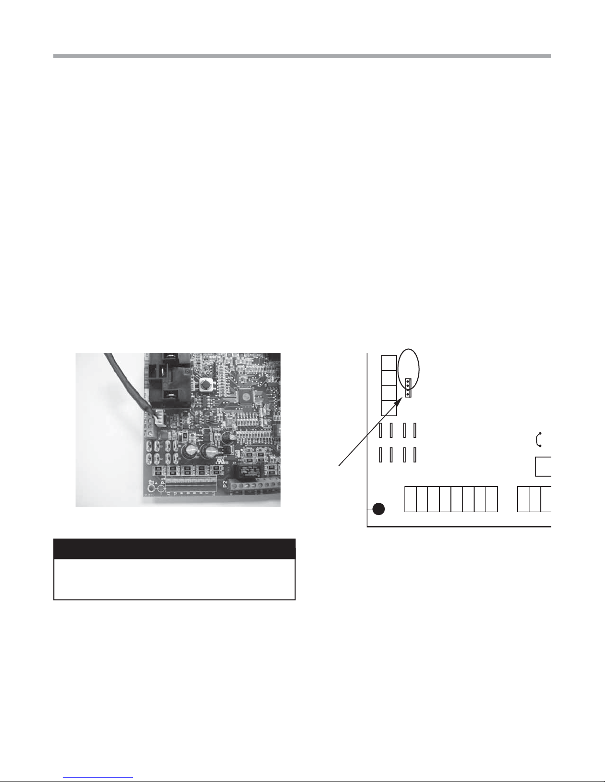
The Service Tool connects to the DXM2 board with a 4-Wire Connector as shown below:
Note: For Vertical Stack models (TSM, TSL) must
order harness for connection to service port outside
chassis. Harness part number 11B0100N27. DXM2 to
service port is factory wired.
DXM2
Board
WARNING!
WARNING!
powered on or connecting backward may damage
service tool.
Connecting wire harness while unit is
DXM2
Board
Service tool
connection
3
ACDU03 Communicating Service Tool
Rev.: November 3, 2017
2.0 Menu Structure
Menu Structure
System Confi guration
Airfl ow Selection
Option Selection
Unit Confi guration
Pump Confi guration
Valve Confi guration
Service Mode
Manual Operation
Control Diagnostics
Dipswitch Confi guration
Fault History
Clear Fault History
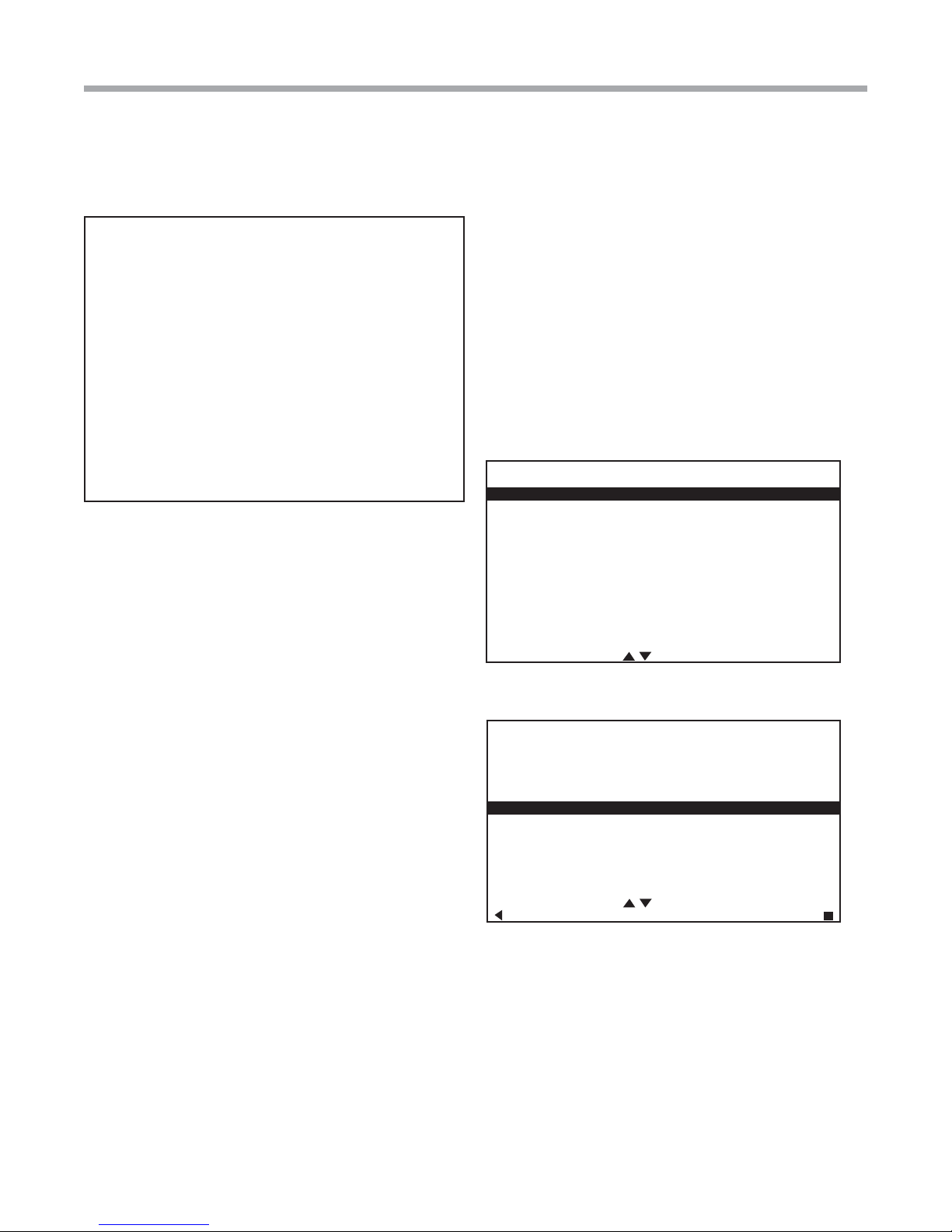
SERVICE TOOL MENU
SYSTEM CONFIG
3.0 System Confi guration
Use the System Confi guration option on the start-up screen
to adjust critical equipment settings.
The System Confi guration information will be automatically
obtained from each communicating control in the system.
Note 1: The Airfl ow Selection menu (section 3.1) will not be
present if the connected communicating control system has
no blower.
Note 2: The Pump Confi guration menu (section 3.4) will
not be present if the connected communicating control is
confi gured for No Loop Confi guration (OTHER).
Note 3: The Valve Confi guration menu (section 3.5) will
not be present if the connected communicating control is
confi gured for No Loop Confi guration (OTHER).
3.1 AIRFLOW SELECTION
Adjust the airfl ow settings for each system operating mode
using the up/down arrow buttons. Press the center button to
select each item.
• Airfl ow Settings (defaults stored in control) -
valid range: obtained from control (in 25 CFM
increments)
• Blower Off Delay (default 60 seconds) – valid
range: 0 to 255 seconds (in 5 second increments)
SERVICE MODE
ACDU03 1.00
SELECT OPTION
Start-up Screen
SYSTEM CONFIGURATION
AIRFLOW SELECTION
OPTION SELECTION
UNIT CONFIG TES026
PUMP CONFIGURATION
SELECT OPTION
PREVIOUS SELECT
System Confi guration Menu
NOTE 1: The Airfl ow Settings will only be present if the
connected communicating control is confi gured for ECM
blower.
NOTE 2: If multiple units are connected to one thermostat,
refer to section 3.6 for unit selection.
4
Geothermal Heat Pump Systems
 Loading...