

Page 1
CLIMATEC
Pressure Inlet Controller
CLT4
Version 4.0
HANDBOOK
1
Climatec Systems Ltd Old Wharf Industrial Estate Ledbury Herefordshire HR8 2JQ Tel 01531 631161 Fax 01531 631165 Email [email protected]
Page 2
MAIN SETTINGS (RUN MODE)
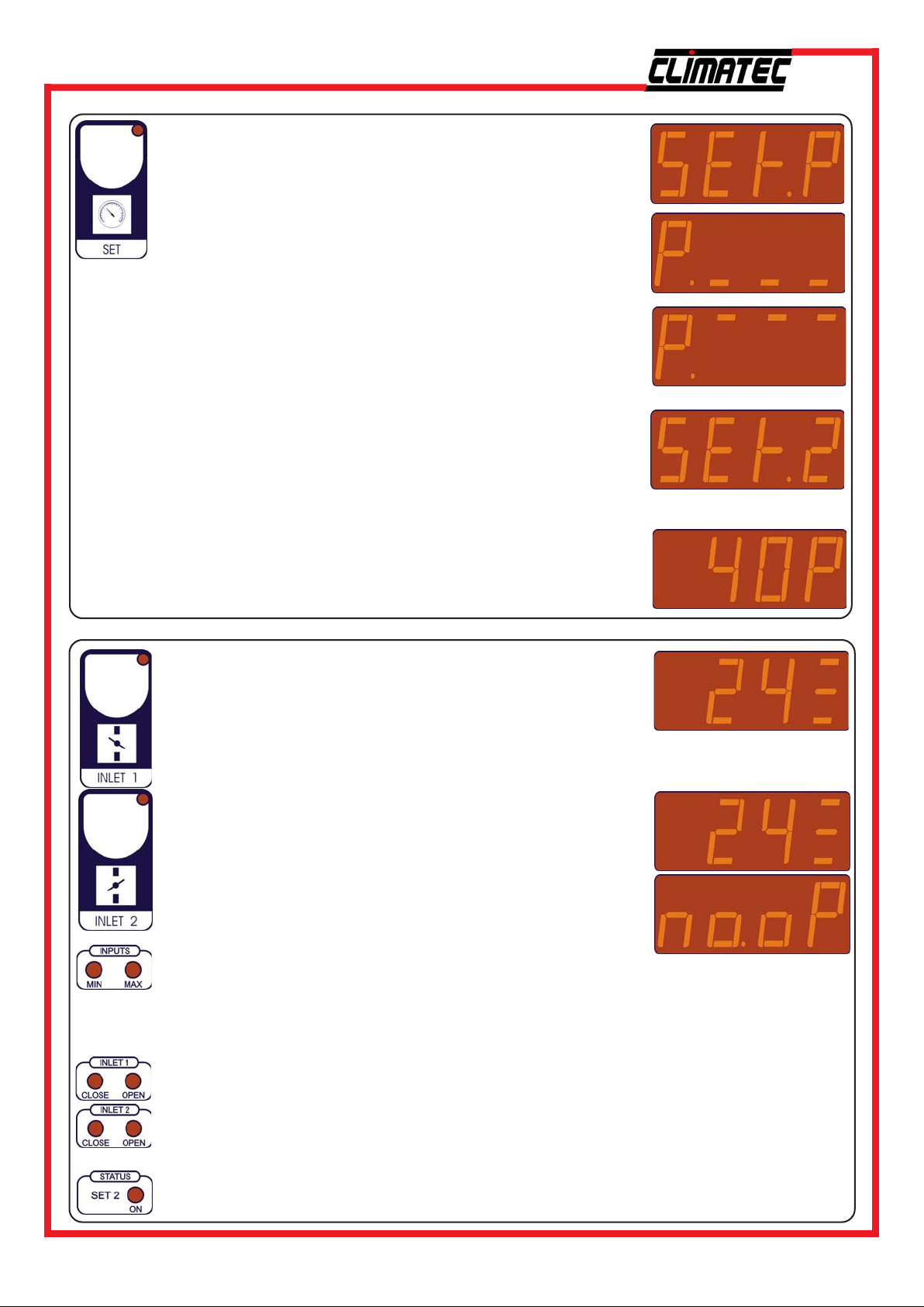
Press SET.
Display will change to show the set pressure.
Press + or - to adjust.
Press SET again.
Display will change to show the minimum inlet position.
Press + or - to adjust.
(This setting is only used when the Minimum Input contact is open.)
Press SET again.
Display will change to show the maximum inlet position.
Press + or - to adjust.
(This setting is only used when the Maximum Input contact is open.)
Press SET again.
Display will change to show the SEt.2 pressure setting.
Press + or - to adjust.
This setting is controlled based upon an external signal from, for
example a HP1 1 thermost at. This can provide a “cold outside temperature” pressure setting.
(This setting is only used when the SEt.2 Input contact is closed.)
VIEWING
Press SET again to return to the current pressure reading.
Press INLET 1.
INLET 1 button indicator will illuminate and the display will
change to show the current position of inlet 1.
Press INLET 2.
INLET 2 button indicator will illuminate and the display will
change to show the current position of inlet 2.
If INLET 2 is disabled (n.inL=1 (see COSt settings)) and INLET 2
is pressed the display will change to indicate no operation:
These lamps illuminate to indicate the control condition.
When MIN is lit this indicates that the minimum set position is active. When this light is
not lit the minimum set position is set at 0%
When MAX is lit this indicates that the maximum set position is active. When this light is
not lit the maximum set position is set at 100%.
These lamps illuminate to show the current state of the inlet control.
When CLOSE is lit this indicates that the controller is closing the inlet.
When OPEN is lit this indicates that the controller is opening the inlet.
This lamp is illuminated when the SEt.2 Input Contact is made. When this lamps is lit
the controller runs the inlets to the SEt.2 pressure setting (See MAIN SETTINGS).
2
Climatec Systems Ltd Old Wharf Industrial Estate Ledbury Herefordshire HR8 2JQ Tel 01531 631161 Fax 01531 631165 Email [email protected]
Page 3
INLET 1 POTENTIOMETER CALIBRATION PROCEDURE
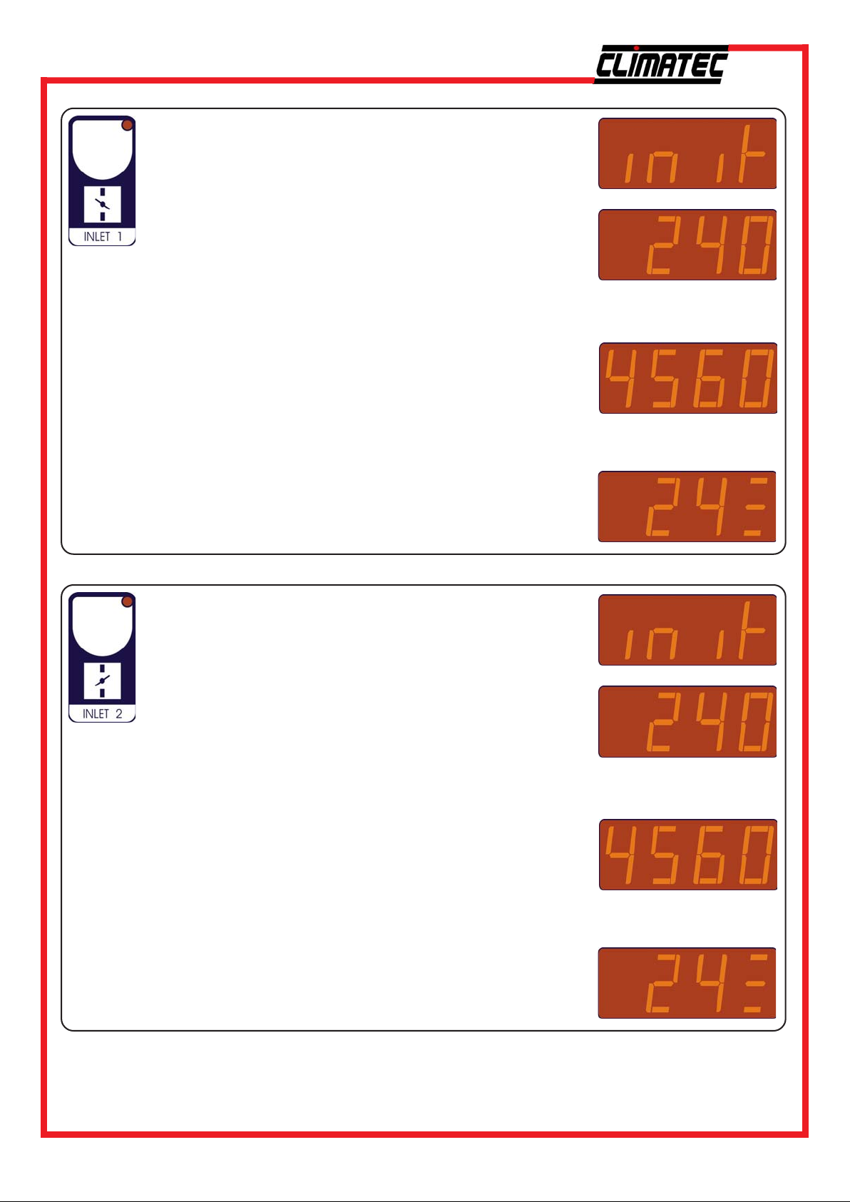
Press and hold INLET 1.
Display will change to show the start of the calibration procedure:
Continue to hold INLET 1 until the display changes to read the
potentiometer readout:
Release INLET 1.
The controller will drive the inlet fully closed (ensure that the
auto-manual switch is in the auto position).
When the inlets are in the fully closed position and the
potentiometer readout has stopped moving press INLET 1.
The controller will drive the inlet fully open.
When the inlets are in the fully open position and the
potentiometer readout has stopped moving press INLET 1.
The calibration procedure is complete.
The display will change to show the current inlet position.
INLET 2 POTENTIOMETER CALIBRATION PROCEDURE
Press and hold INLET 2.
Display will change to show the start of the calibration procedure:
Continue to hold INLET 2 until the display changes to read the
potentiometer readout:
Release INLET 2.
The controller will drive the inlet fully closed (ensure that the
auto-manual switch is in the auto position).
When the inlets are in the fully closed position and the
potentiometer readout has stopped moving press INLET 2.
The controller will drive the inlet fully open.
When the inlets are in the fully open position and the
potentiometer readout has stopped moving press INLET 2.
The calibration procedure is complete.
The display will change to show the current inlet position.
3
Climatec Systems Ltd Old Wharf Industrial Estate Ledbury Herefordshire HR8 2JQ Tel 01531 631161 Fax 01531 631165 Email [email protected]
Page 4
COSt SETTINGS
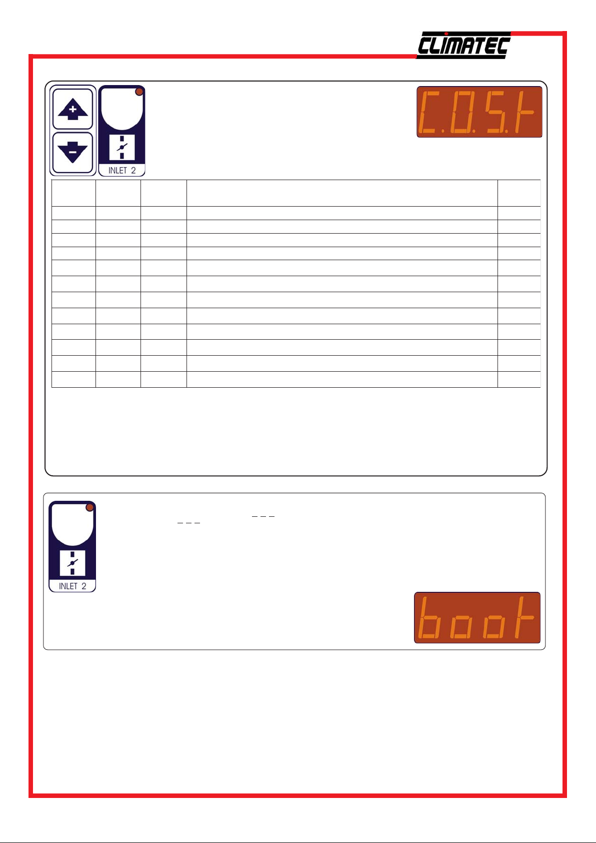
To enter COSt settings press and hold the + & keys until COSt is displayed.
Press INLET 2 to scroll through the settings,
using the + & - keys to adjust the setting values
as required.
gnitteS
.b.n
Fo.t
GorP
.b.n.L
EtnI
P
1.C
1.OP
2.CP
2.OP
EPYt
Lni.n
rP.dA
*1) For more details see Operating Diagram.
*2) The amount the inlet will move after each waiting time (t.oF).
*3) tYPE=1 DP59/W Pressure Sensor (0-300 Pascal = 0-3 mBar)
tYPE=2 Climatec Pressure Sensor (0-100 Pascal = 0-1 mBar)
To return to Run Mode press INLET 1.
tluafeD
eulaV
P6
"5
%3
%2
"1
0
0001
0
0001
1=
2=
0.0
ruoY
eulaV
noitpircseDsetoN
)lacsaP(dnablartueN
gnitiaW
stnemevomtelnineewtebemit
tnemevomtelni%
dnablartuen%tnemevoMtelnI
emitnoitargetnignidaererusserP
seR
tupnierusserpfoepyT
stelniforebmuN
noitcerrocrosneserusserP
1*
2*
noitisopesolCniretemoitnetop1telnIfoecnatsiseR
noitisopnepOniretemoitnetop1telnIfoecnatsiseR
noitisopesolCniretemoitnetop2telnIfoecnatsiseR
noitisopnepOniretemoitnetop2telnIfoecnatsi
3*
PRESET PROGRAMS
On delivery this processor is programmed with the following (variable) settings:
Set.P = 40P, P. = 0%, P. = 100%, Set.2 = 40P
The COSt values are shown in COSt Programming section.
To return to these settings at any time:
Power off the processor, press and hold INLET 2 and switch the
power on:
After 2 seconds boot message will be displayed:
release INLET 2.
4
Climatec Systems Ltd Old Wharf Industrial Estate Ledbury Herefordshire HR8 2JQ Tel 01531 631161 Fax 01531 631165 Email [email protected]
Page 5
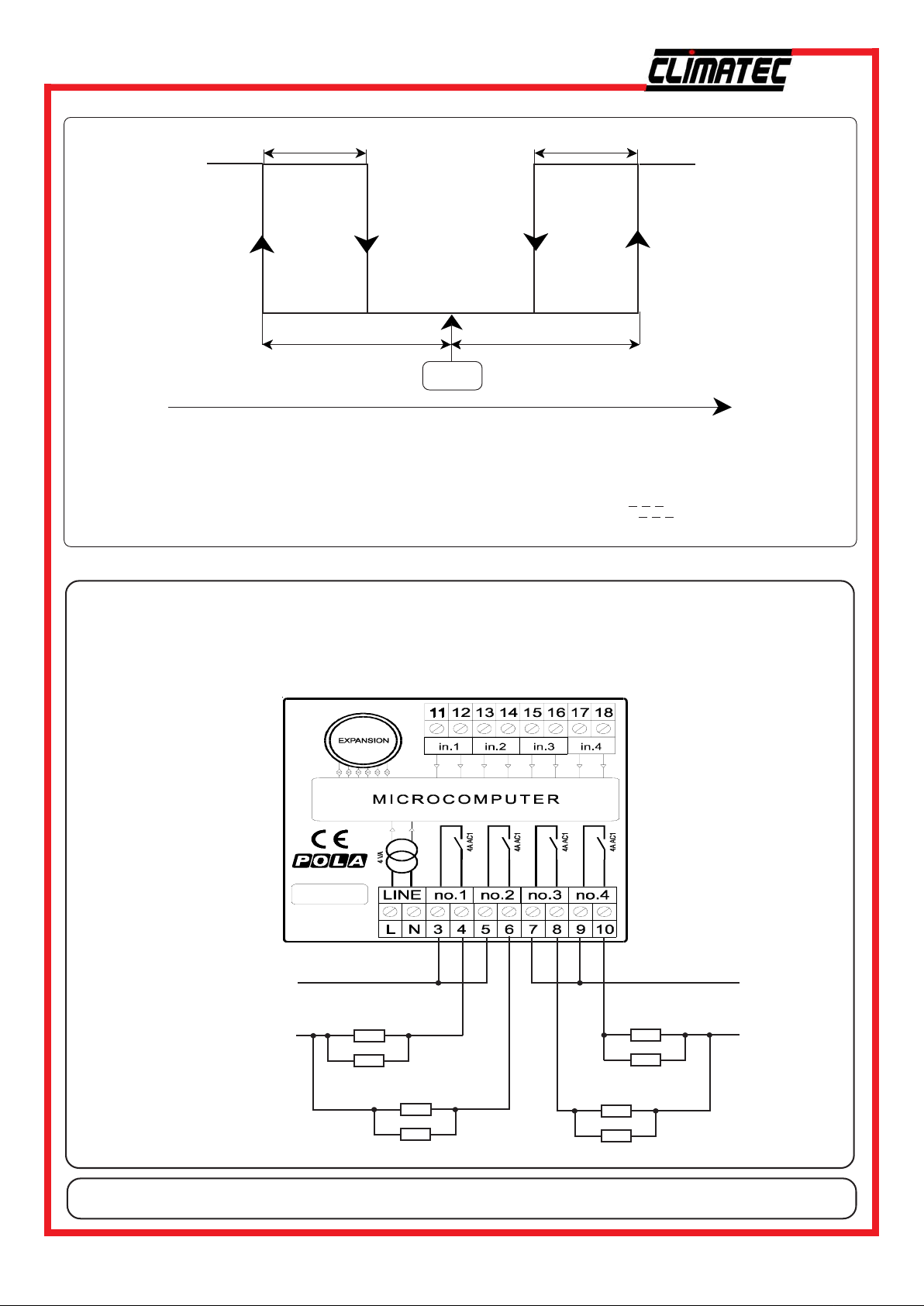
OPERATING DIAGRAM
1 Pascal 1 Pascal
ON
operation conditioned
by t.of and ProG (see
COSt).
operation conditioned
by t.of and ProG (see
COSt).
ON
OPENCLOSE
OFF
1/2 n.b. 1/2 n.b.
SEt.P or Set.2
External conditioning:
C1= Change set input contact (from SEt.P to SEt.2 value).
C2= Minimum % input contact (minimum opening is conditioned from P. setting).
C3= Maximum % input contact (maximum opening is conditioned from P. setting).
OFF
INCREASING PRESSURE SIGNAL
SNUBBER DIAGRAM
If operating 240 volt relays or contactors, you must:
a) Ensure that common feed (terminals 3, 5, 7 & 9) is supplied via a 4 amp fuse.
b) A snubber network (supplied as an extra) is connected across the coil of the
contactor.
L
240Volt
Supply
N
Contactor Coil
Contactor Coil
L
240Volt
Supply
N
Snubber
Contactor Coil
Snubber
Snubber
Contactor Coil
Snubber
IF IN DOUBT PLEASE CALL CLIMATEC SYSTEMS FIRST.
5
Climatec Systems Ltd Old Wharf Industrial Estate Ledbury Herefordshire HR8 2JQ Tel 01531 631161 Fax 01531 631165 Email [email protected]
Page 6
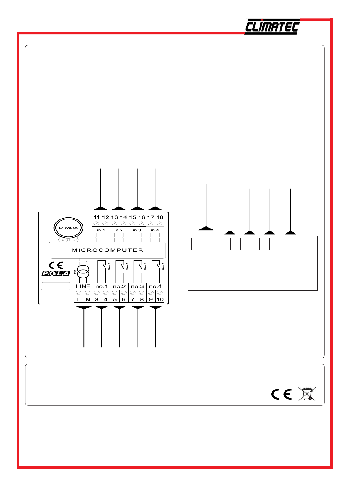
INSTALLATION
For correct installation, follow the instructions below very carefully.
It is recommended to install the controller properly so that it complies with current regulations, and also
to use a max 4Amp.F fuse to prevent the relay output contacts from getting damaged and ensure they
stay in perfect running order (terminals 3-4... 9-10 of the HP module connector).
How to connect the potentiometers and Input contacts
Connect the potentiometer provided as shown in the diagram below: connect the 1 Kohm potentiometer
(max 10Kohm) applied to the flap motor.
For remote connections use a standard 0.5-square millimetre two-pole wire for each potentiometer,
taking great care over the connections, by insulating and sealing any joins carefully.
How to connect the line
Connect line on terminals L-N; protect supply with adequate fuse.
How to connect the contacts
Connect terminals 3-4...9-10 on the terminal block (contacts up to 4AMP.AC1) to the inlet power pack
as shown in the diagram below.
DEPRESSIOMETER
INLET 1
INLET 2
INPUT
CONTACTS
- +
1 2 3 4 5 6 7 8 9 10 11 12
CLT4
230V LINE
INLET 1 CLOSE
INLET 1 OPEN
INLET 2 CLOSE
INLET 2 OPEN
Climatec Systems Limited, Ledbury, Herefordshire. HR8 2JQ.
www.climatec.co.uk
As it company policy to continually improve the products the Manufacturers
reserve the right to make any modifications thereto without prior notice.
They cannot be held liable for any damage due to malfunction.
Pressure Sensor
Input /Output
For Use ONLY with CLIMATEC
pressure sensor
Connection to CLT4
terminals 17 & 18
SEt .2 contact
(Normally Open)
In Out Gnd
input
++ -
CLT4 Digital to Analogue Interface
Minimum Input
(Normally Closed)
Maximum Input
(Normally Open)
No Connection
13.05.09
6
Climatec Systems Ltd Old Wharf Industrial Estate Ledbury Herefordshire HR8 2JQ Tel 01531 631161 Fax 01531 631165 Email [email protected]
Page 7
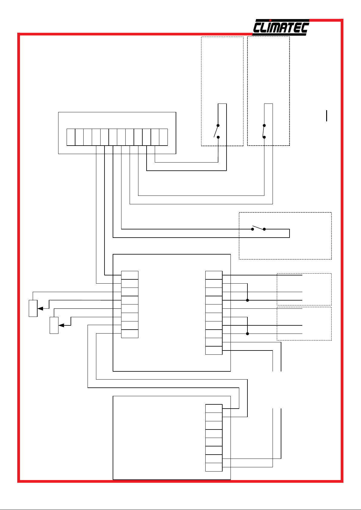
CLT4 Wiring Diagram
for
DP59/W Pressure Sensor
(tYPE=1)
1
2
3
4
5
6
7
8
9
101112
CLT4
Interface
Contact
Maximum Lock
(Normally open from
total stages))
Fan Panel (2/3rds of
Contact
Minimum Lock
(Normally closed from
Fan Panel stage 1)
NOTE: External Contacts
Set 2 Contact
unit these external contact
Due to the sensitivity of the
from external
(Normally OPEN,
contactor auxilliaries
must be via a relay and not
controller)
Inlet 2
Open
Close
Common
Open
Inlet 2
Drive
Signals
CLT4
Close
11 12 13 14 15 16 17 18
12345678910
LN
Feedback Pot
Inlet 1
Common
Inlet 1
Drive
Signals
Feedback Pot
Mains
Supply
240VAC
DP59/W
Pressure Sensor
Climatec Systems Ltd Old Wharf Industrial Estate Ledbury Herefordshire HR8 2JQ Tel 01531 631161 Fax 01531 631165 Email [email protected]
12345678
LN
7
Page 8
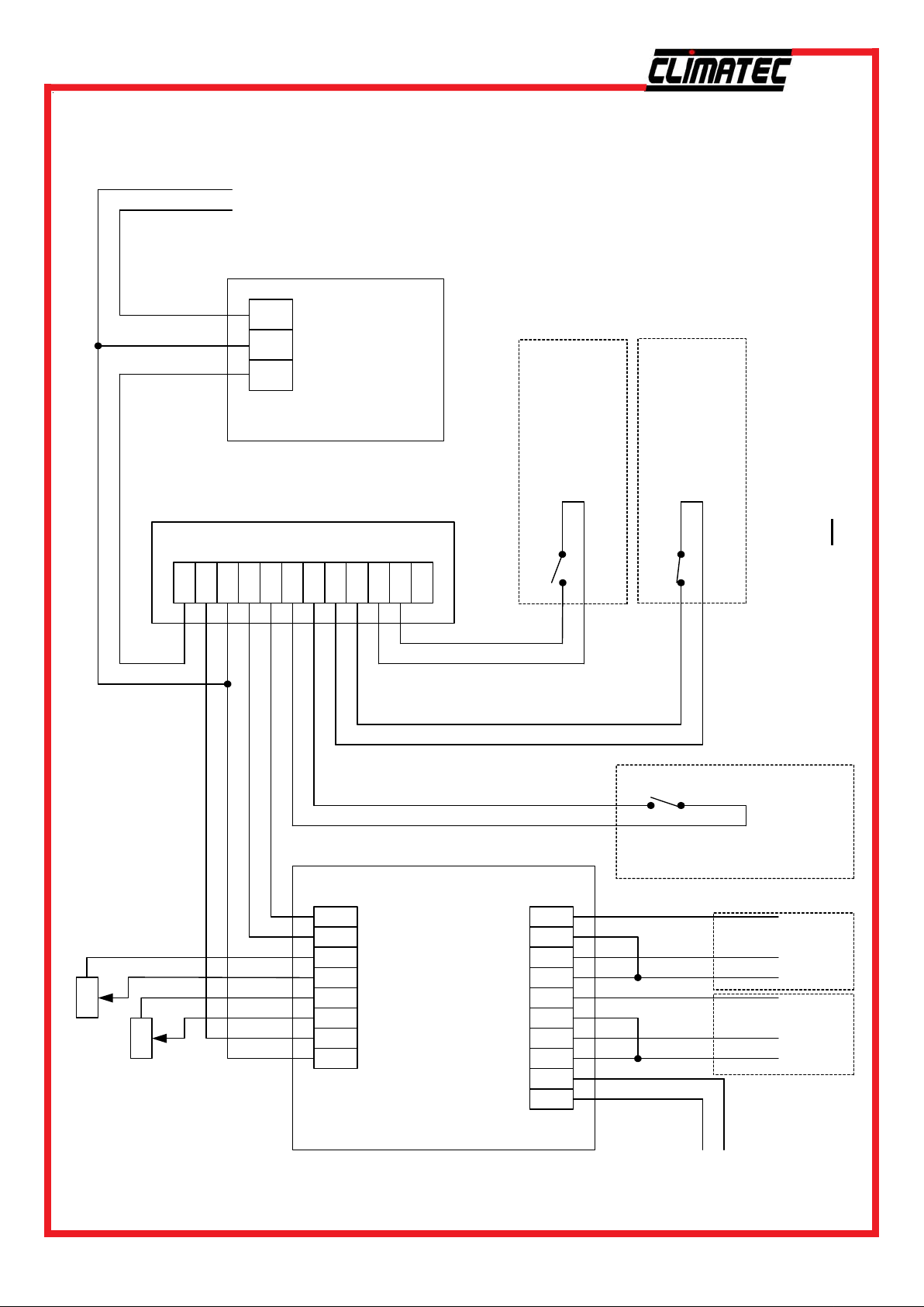
CLT4 Wiring
Diagram
+-
24VDC
Supply
PCB)
power supply
(from existing
for
Climatec
Pressure Sensor
(tYPE=2)
Sig GND +V
1
2
3
4
5
6
7
8
9
Sensor
Climatec Pressure
101112
CLT4
Interface
Contact
Maximum Lock
(Normally open from
Fan Panel (2/3rds of
total stages))
Contact
Minimum Lock
(Normally closed from
Fan Panel stage 1)
Inlet 2
Feedback Pot
Inlet 1
11 12 13 14 15 16 17 18
CLT4
12345678910
LN
NOTE: External Contacts
Due to the sensitivity of the
Set 2 Contact
Open
Close
Common
Open
Close
Common
unit these external contact
must be via a relay and not
from external
(Normally OPEN,
Drive
Inlet 2
Drive
Inlet 1
contactor auxilliaries
controller)
Signals
Signals
Feedback Pot
Mains
Supply
240VAC
Climatec Systems Ltd Old Wharf Industrial Estate Ledbury Herefordshire HR8 2JQ Tel 01531 631161 Fax 01531 631165 Email [email protected]
8
 Loading...