

ClimaGuard TX231416100, TX332816100, TX231448100, TX385616100, TX332848100 User Manual
...
CLIMAGUARD™
Air-To-Air ouTdoor HeAT excHAngers
Tx23, Tx33, Tx38, Tx52 Models
INSTRUCTION MANUAL
Rev. G
© 2013 Pentair Equipment Protection 87976519
P/N 10-1008-221

TABLE OF CONTENTS
RECEIVING THE AIR CONDITIONER ...........................................................................................................................................3
TESTING THE HEAT EXCHANGER ...............................................................................................................................................3
INSTALLATION INSTRUCTIONS ..................................................................................................................................................4
PRINCIPLES OF OPERATION ......................................................................................................................................................4
MAINTENANCE ............................................................................................................................................................................4
Air Movers .................................................................................................................................................................................................. 4
Ambient Air In/Out Screens ....................................................................................................................................................................... 4
TX23 Series ................................................................................................................................................................................................ 5
TX23 Mounting Cutout Dimensions ........................................................................................................................................................... 5
TX23 DC Model Drawing ............................................................................................................................................................................ 6
TX23 AC Model Drawing ............................................................................................................................................................................ 6
TX33 Series ................................................................................................................................................................................................ 7
TX33 Mounting Cutout Dimensions ........................................................................................................................................................... 7
TX33 DC Model Drawing ............................................................................................................................................................................ 8
TX33 AC Model Drawing ............................................................................................................................................................................ 8
TX38 Series ................................................................................................................................................................................................ 9
TX38 Mounting Cutout Dimensions ........................................................................................................................................................... 9
TX38 DC Model Drawing .......................................................................................................................................................................... 10
TX38 AC Model Drawing .......................................................................................................................................................................... 10
TX52 Series .............................................................................................................................................................................................. 11
TX52 Mounting Cutout Dimensions ......................................................................................................................................................... 11
TX52 DC Model Drawing .......................................................................................................................................................................... 12
TX52 AC Model Drawing .......................................................................................................................................................................... 12
TX23 Components List ............................................................................................................................................................................. 13
TX33 Components List ............................................................................................................................................................................. 13
TX38 Components List ............................................................................................................................................................................. 13
TX52 Components List ............................................................................................................................................................................. 13
TX DC Wire Diagram (see label on unit for actual options) .................................................................................................................... 14
TX23 AC Wire Diagram (see label on unit for actual options) ................................................................................................................ 15
TX33, TX38, TX52 AC Wire Diagram (see label on unit for actual options) ............................................................................................ 15
TROUBLE SHOOTING AC Units .................................................................................................................................................16
Basic Trouble Shooting Check List ......................................................................................................................................................... 16
TROUBLE SHOOTING DC Units .................................................................................................................................................17
Basic Trouble Shooting Check List ......................................................................................................................................................... 17
WARRANTY ................................................................................................................................................................................18
RETURN AND REPAIR POLICY ..................................................................................................................................................18
LIMITATION OF LIABILITY ..........................................................................................................................................................19
- 2 -
NOTE: Some of the information in this manual may not apply if a special unit was ordered. If
additional drawings for a special unit are necessary, they have been inserted. Contact Pentair
Equipment Protection if further information is required.
© 2013 Pentair Equipment Protection
87976519

RECEIVING THE AIR CONDITIONER
Inspect the Heat Exchanger. Check for concealed damage that may have occurred during shipment. Look for
dents, scratches, loose assemblies, etc. Damage evident upon receipt should be noted on the freight bill. Damage
should be brought to the attention of the delivering carrier -- NOT to Pentair Equipment Protection -- within
15 days of delivery. Save the carton and packing material and request an inspection. Then file a claim with the
delivering carrier.
Pentair Equipment Protection cannot accept responsibility for freight damages; however, we will assist you in any
way possible.
TESTING THE HEAT EXCHANGER
TEST FOR FUNCTIONALITY BEFORE MOUNTING THE HEAT EXCHANGER TO THE ENCLOSURE.
Refer to nameplate for proper electrical current requirements, and then connect power cord to a properly
grounded power supply. Minimum circuit ampacity should be at least 125% of the amperage shown in the design
data section for the appropriate model. No other equipment should be connected to this circuit to prevent
overloading.
Operate the heat exchanger for several minutes. No excessive noise or vibration should be evident during this
run period. Ambient air mover may not be energized at temperatures low enough to not require cooling. On DC
powered units, air movers may not always be running at full speed.
87976519
© 2013 Pentair Equipment Protection
- 3 -

INSTALLATION INSTRUCTIONS
1. Inspect heat exchanger. Verify functionality before mounting the heat exchanger, see TESTING THE
HEAT EXCHANGER on page 3.
2. Determine if the unit is to be surface or recess mounted. Using the appropriate cutout dimensions
shown in this manual, prepare the enclosure opening for either surface or recess mounting.
3. Using the gasket kit provided, install gaskets to heat exchanger.
4. Mount heat exchanger on enclosure using mounting screws provided. Torque screws to 25 in-lbs
(2.82 Nm).
5. Refer to unit nameplate for electrical requirements. Connect the power cord to a properly
grounded power supply. Use of an extension cord is not recommended. Electrical circuit should be
fused with slow blow or HACR circuit breaker.
PRINCIPLES OF OPERATION
Operating the heat exchanger below the minimum ambient temperature or above the maximum ambient
temperatures indicated on the nameplate voids all warranties.
It is recommended that the warranty section of this manual be read in order to familiarize yourself with
parameters of restricted operation.
MAINTENANCE
AIR MOVERS
Air mover motors require no maintenance. All bearings are lubricated during manufacturing for the life of the
motor.
If the ambient air mover should fail, it is not necessary to remove the heat exchanger from the cabinet or
enclosure to replace it. The ambient air mover is mounted on a bulkhead and is easily accessible by removing the
front cover.
Caution! Operation of the heat exchanger in areas containing airborne caustics or chemicals can rapidly
deteriorate aluminum cores and air movers. Contact Pentair Equipment Protection for special recommendations.
AMBIENT AIR IN/OUT SCREENS
In dirty environments, the bug screens on the front cover may need to be cleaned periodically to maintain
adequate cooling performance. The front cover should be removed from the heat exchanger and set aside for
cleaning with water, air or scrubbed clean with a brush.
- 4 -
© 2013 Pentair Equipment Protection
87976519
TX23 SERIES
25 Watts/°C (14 Watts/°F)
Model Voltage Hz
TX23-1424-XXX 24VDC 3.4 65/149 -40/-40 30/13.6
TX23-1448-XXX 48VDC 1.8 65/149 -40/-40 30/13.6
TX23-1416-XXX 115VAC 50/60 TBD 1 65/149 -40/-40 30/13.6
TX23-1426-XXX 230VAC 50/60 TBD 1 65/149 -40/-40 30/13.6
XXX will be replaced with a three-digit number designating all desired options. Consult the factory for specific model numbers.
Full Load
Amps
Phase
Maximum
Temperature
(°C/°F)
Minimum
Temperature
(°C/°F)
Shipping
Weight
(lb./kg)
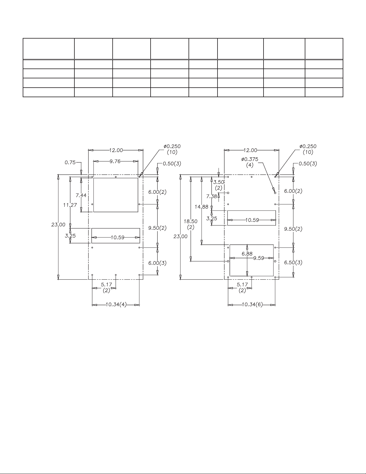
TX23 MOUNTING CUTOUT DIMENSIONS
87976519
External Mounting Internal Mounting
CUTOUT INSTRUCTIONS
(As viewed from outside of enclosure)
NOTE: Dashed lines represent heat exchanger.
© 2013 Pentair Equipment Protection
- 5 -
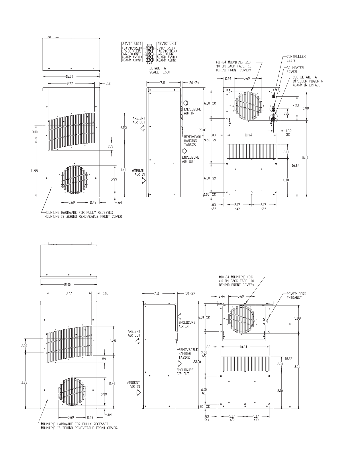
TX23 DC MODEL DRAWING
TX23 AC MODEL DRAWING
- 6 -
© 2013 Pentair Equipment Protection
87976519
 Loading...