


ClimaCool IOM FLEX User Manual

ClimaCool IOM
FLEX SERIES
Water-Cooled Modular Chillers
Installation, Operation &
Maintenance Manual
®

®
ClimaCool works continually to improve
its products. As a result, the design and
specifications of each product at the time for
order may be changed without notice and
may not be as described herein. Please contact
ClimaCool's Customer Service Department at
(405) 745-3185 for specific information on the
current design and specifications. Statements
and other information contained herein are not
express warranties and do not form the basis
of any bargain between the parties, but are
merely ClimaCool's opinion or commendation
of its products.
Refer to www.climacoolcorp.com for complete
warranty details.
2
www. cli mac ool cor p.c omwww. cli mac ool cor p.c om

®
CONTENTS PAGES
Model Numbers/Safety . . . . . . . . . . . . . . . . . . . . . . . . . . . . . 1
Inspection
Site Preparation
Installation
Dimensional Data
Rigging and Lifting
Service Clearances
Vibration Isolation
Electrical Connection
Water Piping System
Water Piping Configurations
Hydronic Refrigeration (Drawing)
Filling the Water System
Water Treatment
Condenser Water Temperature Requirements
Strainer Systems
Stainless Steel Strainer Option
Automatic Timer Flush Package Option
Pressure Differential Alarm Package
Y Type and Basket Type Strainers
Pre-Start Up
Start Up
Pre-Start Up Check List
Start-Up and Warranty Registration Form
Chiller Operation and Maintenance
Heat Exchangers (Drawings)
Operation Limitations
Physical Data
Application Parameters
Compressor Information
Refrigeration Circuit (Drawings)
Refrigeration System Re-Processing
Sequence of Operation
Electrical Data
Power Distribution (Drawing)
Wiring Diagrams
Troubleshooting Guide
Warranty Information
. . . . . . . . . . . . . . . . . . . . . . . . . . . . . . . . . . . . 2
. . . . . . . . . . . . . . . . . . . . . . . . . . . . . . . . . 3
. . . . . . . . . . . . . . . . . . . . . . . . . . . . . . . . . . . 3
. . . . . . . . . . . . . . . . . . . . . . . . . . . . . . . . 4
. . . . . . . . . . . . . . . . . . . . . . . . . . . . . . . 5
. . . . . . . . . . . . . . . . . . . . . . . . . . . . . . . 6
. . . . . . . . . . . . . . . . . . . . . . . . . . . . . . . 7
. . . . . . . . . . . . . . . . . . . . . . . . . . . . . . 8
. . . . . . . . . . . . . . . . . . . . . . . . . . . . . . 9
. . . . . . . . . . . . . . . . . . . . . . . . . .10
. . . . . . . . . . . . . . . . . . . . . . . 11
. . . . . . . . . . . . . . . . . . . . . . . . . . . .12
. . . . . . . . . . . . . . . . . . . . . . . . . . . . . . . . 13
. . . . . . . . . . . . . . . . . 14
. . . . . . . . . . . . . . . . . . . . . . . . . . . . . . . . 15
. . . . . . . . . . . . . . . . . . . . . . . . . 16
. . . . . . . . . . . . . . . . . . . .18
. . . . . . . . . . . . . . . . . . . . . . 21
. . . . . . . . . . . . . . . . . . . . . . . 23
. . . . . . . . . . . . . . . . . . . . . . . . . . . . . . . . . . . 24
. . . . . . . . . . . . . . . . . . . . . . . . . . . . . . . . . . . . . 25
. . . . . . . . . . . . . . . . . . . . . . . . . . . . 26
. . . . . . . . . . . . . . . . . . . 27
. . . . . . . . . . . . . . . . . . . . . . . 28
. . . . . . . . . . . . . . . . . . . . . . . . . . 29
. . . . . . . . . . . . . . . . . . . . . . . . . . . . . . 30
. . . . . . . . . . . . . . . . . . . . . . . . . . . . . . . . . . 31
. . . . . . . . . . . . . . . . . . . . . . . . . . . . . 32
. . . . . . . . . . . . . . . . . . . . . . . . . . . . 33
. . . . . . . . . . . . . . . . . . . . . . . . 34
. . . . . . . . . . . . . . . . . . . . . . 36
. . . . . . . . . . . . . . . . . . . . . . . . . . . . .37
. . . . . . . . . . . . . . . . . . . . . . . . . . . . . . . . . 38
. . . . . . . . . . . . . . . . . . . . . . . . . 39
. . . . . . . . . . . . . . . . . . . . . . . . . . . . . . . .40
. . . . . . . . . . . . . . . . . . . . . . . . . . . . . 43
. . . . . . . . . . . . . . . . . . . . . . . . . . . . . . 45
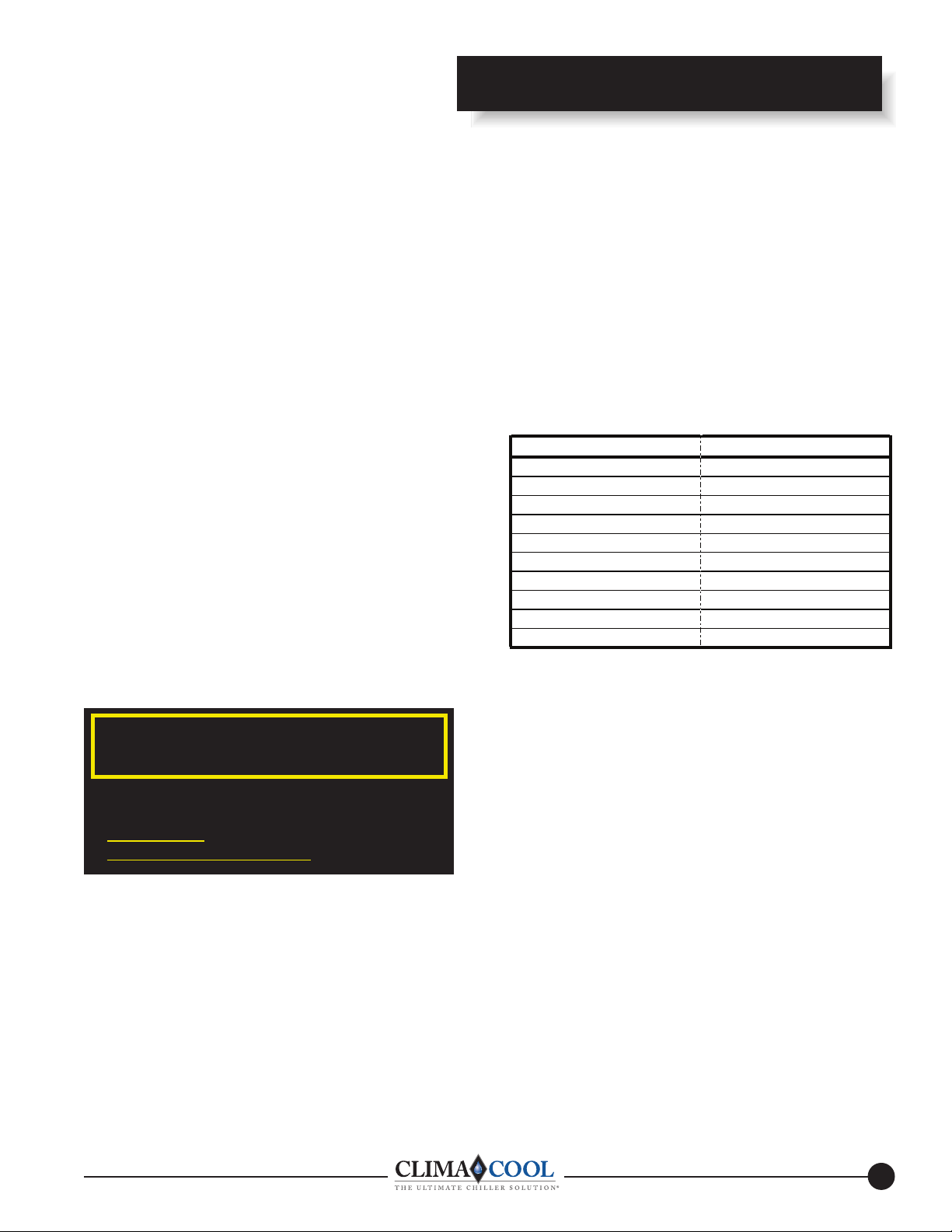
ClimaCool Modular Chillers
MODEL NUMBERS AND SPECIFICATIONS
Dimensions Refrigerant No. Of Nominal
Model No. L x W x H (in.) Voltage Circuits Compressors Tons
FLEX 30 41-7/8” x 29-1/2” x 77”* 208/230/3/60 2 2 30
FLEX 30 41-7/8” x 29-1/2” x 77 ”* 460/3/60 2 2 30
FLEX 30 41-7/8” x 29-1/2” x 77 ”* 575/3/60 2 2 30
FLEX 50 41-7/8” x 33-1/2” x 78 3/8”* 208/230/3/60 2 2 50
FLEX 50 41-7/8” x 33-1/2” x 78 3/8”* 460/3/60 2 2 50
FLEX 50 41-7/8” x 33-1/2” x 78 3/8”* 575/3/60 2 2 50
FLEX 65 43-5/8” x 33-1/2” x 78 3/8”* 208/230/3/60 2 2 65
FLEX 65 43-5/8” x 33-1/2” x 78 3/8”* 460/3/60 2 2 65
FLEX 65 43-5/8” x 33-1/2” x 78 3/8”* 575/3/60 2 2 65
* Dimensions with covers.
� SAFETY WARNING �
High voltage is used to operate this equipment. Failure to observe standard electrical safety procedures may result in serious
injury. Only persons qualified and / or properly trained should attempt to install, operate and maintain this equipment. These
chillers come fully charged with refrigerant. Installation, and start – up should be accomplished by technicians who are fully
certified to handle refrigerants, as required by 40 CFR Part 82, subpart F of the Recycling and Emissions Reduction Act. Scroll
compressors are used in this equipment. Phase verification is required for proper rotation direction. Incorrect rotation will
result in elevated sound and internal overload trip failure.
www. cli mac ool cor p.c om
1

®
Inspection
INSPECTION
Allow a sufficient amount of time to carefully follow these
instructions to assure warranty coverage.
During inspection of the equipment remove the top doors
to check the equipment for any damage during shipment.
Inspect wiring connections, lines from expansion devices,
thermostats, and pressure switches for damage.
General
During any correspondence concerning this machine, always
reference the full model and serial numbers of your modules.
Receipt of the ClimaCool Modules
Upon receipt of the equipment, carefully check the shipment
against the bill of lading. Make sure all modules ordered have
been received. Inspect the carton or crating of each module,
and inspect each module for damage. You must make
proper notation of any shortages or damage on all copies
of the freight bill for your records. Make sure the carrier
completes a common carrier inspection report listing any
shortages or damage.
Note: It is the responsibility of the recipient of the
modules to file all necessary claims with the carrier. In
addition, please notify the ClimaCool Customer Service
Department of all damage immediately. Refer to the
back cover for the Customer Service Department phone
number.
Handling of Modules
The packaging allows for handling by fork lift or pallet
jack (only lift the module from the side). See Lifting and
Transporting Modules (Fig. 3) on page 5. Caution: modules
ARE TOP HEAVY. Please use caution when rigging or
moving.
Rigging for Lifting
Each module should be lifted by using lift straps threaded
through each top header tube. See page 5 - Rigging and
Lifting Procedures.
� WARNING �
To avoid the release of refrigerant into the atmosphere,
the refrigerant circuit of this unit must be serviced only by
technicians who meet local, state and federal proficiency
requirements.
All refrigerant discharged from this unit must be recovered
WITHOUT EXCEPTION. Technicians must follow industry
accepted guidelines and all local, state and federal statutes for
the recovery and disposal of refrigerants.
If a compressor is removed from this unit, system refrigerant
circuit oil will remain in the compressor. To avoid leakage of
compressor oil, the refrigerant lines of the compressor must
be sealed after it is removed.
Storage
Equipment should be stored as shipped in a clean, dry area.
Store modules in an upright position at all times. Plastic wrap
should be left on until the module is ready to be installed.
2
www. cli mac ool cor p.c omwww. cli mac ool cor p.c om
®
Site Preparation/Installation
Preparing for Installation.
Prepare the modules for installation by carefully removing
the module's packaging, unbolt the module from the skid, and
lift the module with a crane or hoist into its final position.
Hardware kits are shipped in separate packaging along with
the modules. Make sure the hardware kits are on site when
connecting the modules.
SITE PREPARATION
Base Requirements
The minimum base requirement for the ClimaCool chiller
is a level surface which has been checked to ensure that it
is capable of bearing the combined operating weight of the
modules (see page 4).
Anti-Vibration Mountings
Although the compressors are installed on anti-vibration
mountings, further isolation of the chiller from the structure
can be achieved by installing vibration-eliminating springs or
pads under the base rails on which the chiller will rest. (see
page 7 - Vibration Isolation).
A factory supplied fastener kit is provided for the adjoining
of each module. Each kit contains (4) gaskets, (32) ¾” fully
threaded studs, (64) heavy duty hex nuts, (64) lock washers,
and (64) flat washers.
A ¾"-10 tap should be run through each weld nut located at
the bottom rear chiller header flange of each module. Screw
the fully threaded studs into these four weld nut locations.
At all other flange hole locations, insert fully threaded studs,
attach washers, lock washers, and nuts from the fastener kit.
The gasket should be placed between the first reference
module and the next module. Slide the next module into
position while guiding the fully threaded studs into the flange
holes of the next module. Finally, the washers, lock washers,
and nuts are applied to the other end of the fully threaded
studs to securely fasten the module flanges.
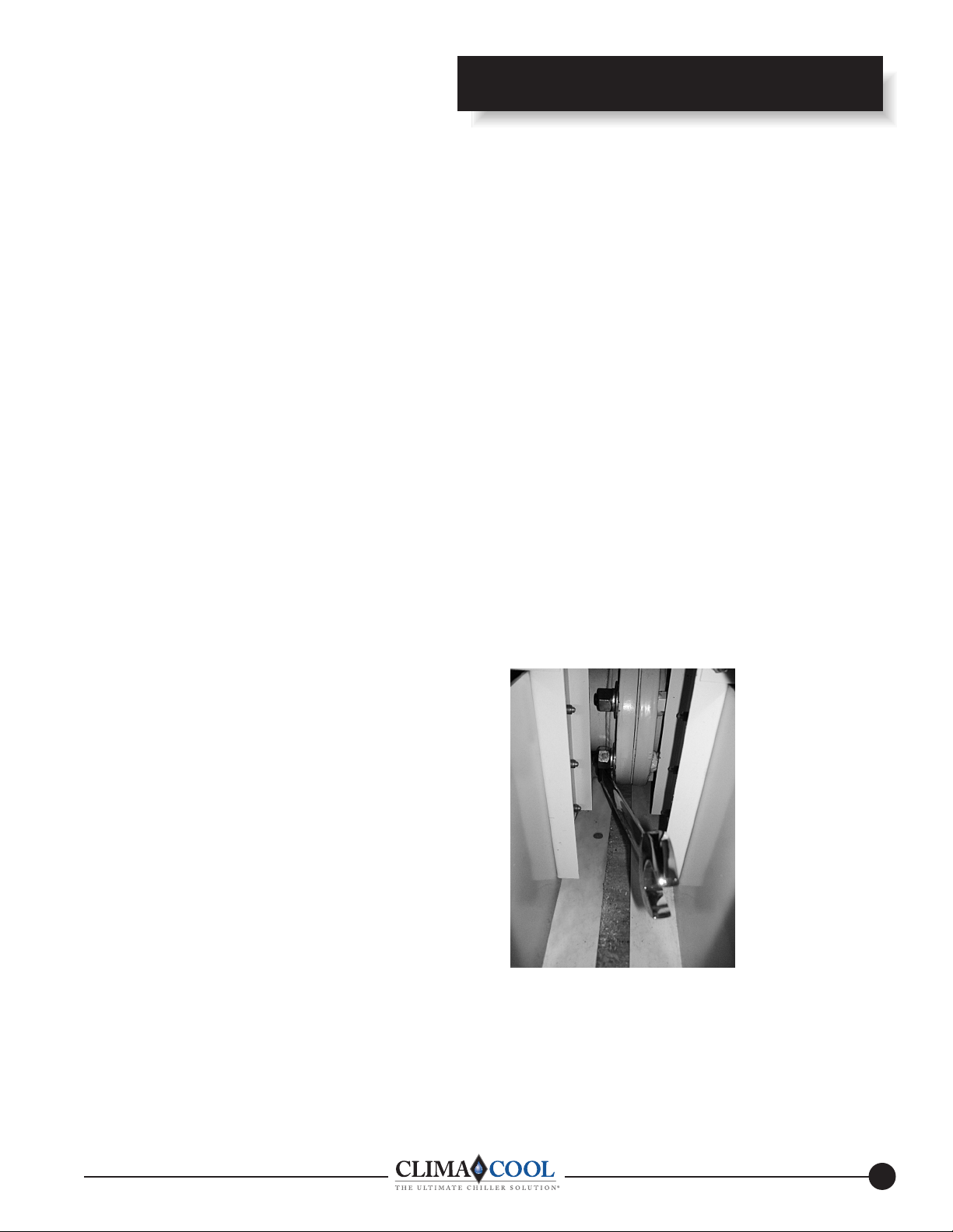
Tighten the flange bolts in a diametrically opposite pattern,
in such a way as to pull the modules together evenly. It will
be necessary to use a ¾" (12 point) box-end wrench when
tightening. As each module is added, the alignment of the
whole package should be confirmed.
Service Access
The minimum space required for electrical panel service is
36" in the front of each module. Allow 24" service clearance
in the back of the module for refrigeration access. Allow a
minimum of 18” of clearance above the module for service.
Allow 12” side clearance of any ClimaCool modular chiller
system (see Service Clearances page 6). Local building or
electrical codes may require additional clearance.
Draining
When performing standard maintenance procedures such
as flushing heat exchanger, it will be necessary to close off
a section of a module. ClimaCool modular chillers come
equipped with isolation valves for this purpose. Access to a
floor drain is helpful when performing standard maintenance
procedures.
INSTALLATION
Assembling Modules
Use of (2) 4” rails (minimum size) is required for ease of
installation. One of the end modules should be chosen as the
reference module and carefully located.
Header and Flange Insulation
Chilled water piping is pre-insulated on each module at the
factory with ¾” closed cell foam rubber. After the bolting the
modules together, the installer must apply insulation on site
over the chilled water header connection flanges.
3
www. cli mac ool cor p.c om
®
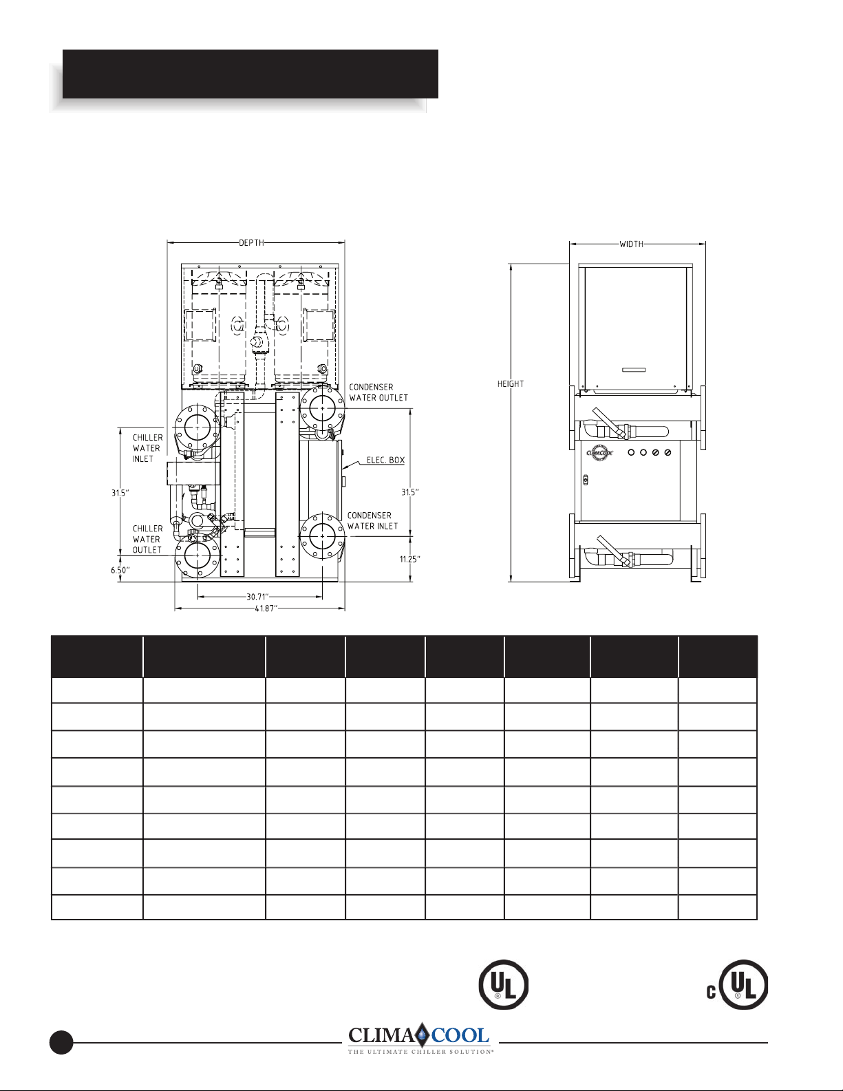
ClimaCool Dimensional Data
The ClimaCool® Modular Chiller -
Module Dimensional Data -
Models 30, 50 & 65 - FLEX Series
Model Voltage Depth Width Height Height (w/covers) Weight
FLEX (inches) (inches) (inches) (inches) (lbs.) (lbs.)
30 208/230/3/60 41-7/8 29-1/2 72-7/8 77 1,669 1,825
30
30
50
50
50
65
65 460/3/60 43-5/8 33-1/2 76-5/8 78-3/8 1,990 2,280
65 575/3/60
NOTES:
1. Unit shipping weight includes refrigerant charge, compressor oil, and shipping base skid. Add two inches to base dimensions
for shipping skid.
2. Operational weight includes refrigerant charge, compressor oil and water.
460/3/60 41-7/8 29-1/2 72-7/8 77 1,669 1,825
575/3/60 41-7/8 29-1/2 72-7/8 77 1,669 1,825
208/230/3/60 41-7/8 33-1/2 76-5/8 78-3/8 1,873 2,163
460/3/60 41-7/8 33-1/2 76-5/8 78-3/8 1,873 2,163
575/3/60 41-7/8 33-1/2 76-5/8 78-3/8 1,873 2,163
208/230/3/60 43-5/8 33-1/2 76-5/8 78-3/8 1,990 2,280
43-5/8 33-1/2 76-5/8 78-3/8 1,990 2,280
• ISO-9001 Certified
1
Oper. Weight2
• Meets NYC Fire Code
4
www. cli mac ool cor p.c omwww. cli mac ool cor p.c om

®
The ClimaCool®Modular Chiller -
Rigging and Lifting Procedures
Rigging (Figures 1 and 2)
Each module should be lifted by using lift straps threaded
through each top header tube.
ClimaCool Rigging and Lifting
A spreader bar should be utilized when rigging with
covers in place.
Lifting and Transporting Modules (Figure 3)
When lifting and transporting the module, it is very im-
for lifting and transporting may damage the module and
void the warranty.
CAUTION
Units are top heavy. Please use caution when
rigging or moving.
www. cli mac ool cor p.c om
snaemrehtoynafoesU.thgirtanwohssadeecorpottnatrop
5
®
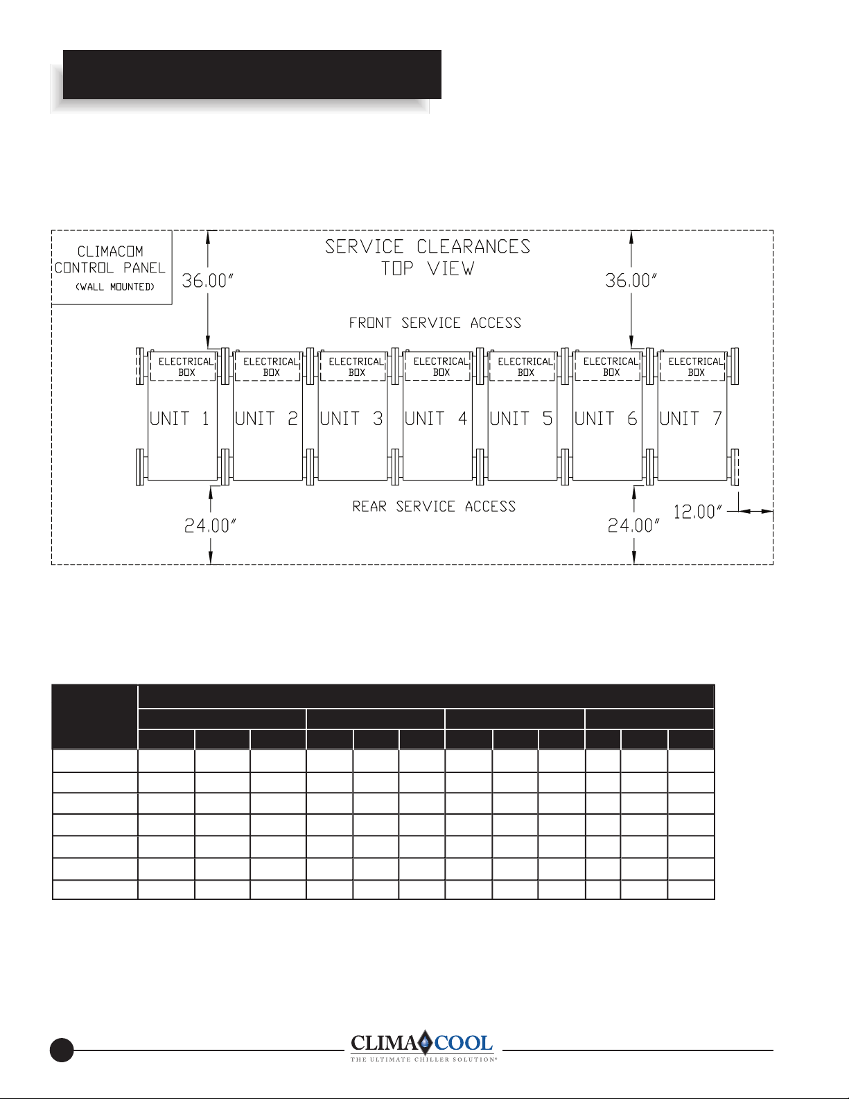
ClimaCool Service Clearances
The ClimaCool® Modular Chiller -
Service Clearances
Recommended Clearances
1. Allow 36” clearance for electrical panels and 24” clearance for rear service access to modules.
2. Allow a minimum of 18" height clearance for service and 12” for side clerances.
3. Local building or electrical codes may require additional clearance. Consult applicable codes.
Modular Chiller Bank Dimensions -
Model Dimensions
FLEX Width (ft./inches) Depth Height
30 50 65 30 50 65 30 50 65 30 50 65
1 module
2 modules
3 modules
4 modules
5 modules
6 modules
7 modules
NOTES:
1. Modular chiller bank width dimensions above include (1/8") between modules, plus (1-1/2") for required blank off plate fl anges
when piping for a direct return (Refer to Water Piping Confi guration - Figure 1). Example: (5) FLEX 65 modules
167-1/2" width + 1-1/2" (Blank off plates) + 5 x 1/8" (fl ange connection gaskets) = 169-5/8" (14' 1-5/8").
2. When piping 1 to 5 or more than 5 modules, use reverse return (Refer to Water Piping Confi guration - Figure 2).
Example: (7) FLEX 30 modules 206-1/2" width + 1-1/2" (Blank off plates left) + 1-1/2" (Blank off plates right) + 8 x 1/8"
(fl ange connection gaskets) = 210-1/2" (17' 6-1/2").
2’ 7-1/8” 2’ 11-1/8” 2’ 11-1/8”
5’ 3/4” 5’ 8-3/4” 5’ 8-3/4”
7’ 6-3/8” 8’ 6-3/8” 8’ 6-3/8”
10’ 0” 11’ 4” 11’ 4”
12’ 5-5/8” 14’ 1-5/8” 14’ 1-5/8”
15’ 7/8” 17’ 7/8” 17’ 7/8”
17’ 6-1/2”
19’ 10-1/2”19’ 10-1/2” 19’ 10-1/2”
w/Connnection Flange Gaskets and Blank Off Plates
(w/o panels) Height (w/ panels)
41-7/8” 41-7/8” 43-5/8” 72-7/8” 76-3/4” 76-3/4” 77” 78-3/8” 78-3/8”
41-7/8” 41-7/8” 43-5/8” 72-7/8” 76-3/4” 76-3/4” 77” 78-3/8” 78-3/8”
41-7/8” 41-7/8” 43-5/8” 72-7/8” 76-3/4” 76-3/4” 77” 78-3/8” 78-3/8”
41-7/8” 41-7/8” 43-5/8” 72-7/8” 76-3/4” 76-3/4” 77” 78-3/8” 78-3/8”
41-7/8” 41-7/8” 43-5/8” 72-7/8” 76-3/4” 76-3/4” 77” 78-3/8” 78-3/8”
41-7/8” 41-7/8” 43-5/8” 72-7/8” 76-3/4” 76-3/4” 77” 78-3/8” 78-3/8”
41-7/8” 41-7/8” 43-5/8” 72-7/8” 76-3/4” 76-3/4” 77” 78-3/8” 78-3/8”
6
www. cli mac ool cor p.c omwww. cli mac ool cor p.c om

®
The ClimaCool® Modular Chiller -
Mounting Rail and Vibration Isolation
Due to the low vibration of the modules, ClimaCool® does not
require the application of spring isolators or pads. Should
isolators or pads be desired, install in accordance with
Figs. 1 and 2.
Figure 1 - Spring Vibration Isolators Option
4” Rail Minimum
Required (by others)
ClimaCool Vibration Isolation
Figure 2 - Vibration Isolation Pads Option
4” Rail Minimum
Required (by others)
NOTE: la u div id ni rep reenigne larutcurts de fiilauq a yb denimreted eb ot si noitubirtsid thgiew dna eziS
job requirements.
7
www. cli mac ool cor p.c om

®
Electrical Connection
DANGER
!
• Electric shock hazard!
• May result in injury or death!
• Disconnect power supply(ies)
before servicing!
• Refer servicing to qualified
service personnel.
• Risque de choc électrique!
• Résultat de mai dans dommages
ou la mort!
• Debrancher avant d’entreprendre
le dépannage de l’appareil!
• Consulter un réparateur qualifie
pour le dépannage.
DANGER
!
Connecting the Water Piping to Modules
Water piping must be installed in accordance with
applicable codes and standards. Flexible connections and
supports should be installed to prevent load or stress on the
module's flange connections (see page 10 - Water Piping
Configurations).
ELECTRICAL CONNECTION
The compliance of the installation to relevant codes is
the responsibility of the installer. Before carrying out any
electrical work, confirm that the main supply is isolated.
The installer must ensure that the correct electrical drawing is
available.
Inter-Module Power Wiring
The power for all modules is taken from a fused supply
within the main panel. A typical power wiring is located on
page 43 - Power Distribution.
Inter-Module Control Wiring
After the power wiring has been run, the control wires can
then be connected. The wires should be carefully marked
and installed in the terminals shown on the wiring diagram.
External control wires should be connected to the relevant
terminals and devices. Wiring to the sensors should not be run
with the power wiring.
Control Wiring Sizes and Lengths
When running control wires, proper gauged wires should
be used. With 14 AWG the maximum distance allowed is
250 feet. With 16 AWG, 100 feet is acceptable. You should
not exceed 50 feet when using 18 AWG. These lengths and
gauges are for the use of 24 volt control circuits.
Incoming Power Wiring
Incoming power should be supplied from a suitable
disconnect switch. Proper grounding of the module is
mandatory.
Electrical Phase Sequencing
Proper clockwise rotation for scroll compressor motors is
important to prevent damaging the compressors. If you
have access to a phase sequence indicating instrument it
is recommended to use this following the manufactures
directions. If not, you may “bump test” the compressors
one at a time with pressure gauges attached to the high and
low gauge ports of the compressors to check for proper
rotation. Energize the compressor for a few seconds to
ensure the discharge pressure gauge increases significantly.
If the discharge pressure does not increase, proper rotation
is reversed. You can quickly reverse compressor rotation by
opening the main electrical disconnect and switching any two
of the main power supply leads feeding that compressor's
contactor.
Proper Voltage Balance
Occasionally, in three phase circuits, a voltage imbalance
occurs between phases. It is not recommended to operate
equipment when an imbalance greater than 2% occurs. This
causes motors to run at high temperatures and may affect
their longevity. The following example describes how to
calculate the average voltage of the three phases to see if the
imbalance is greater than 2%.
Example:
Line one = 226v Line two = 230v Line three = 228v
The average is: 226+230+228 = 228v
3
Next, 100(228-226) = 0.9%
228
The voltage imbalance of the three phase circuit is 0.9%.
This is well under the 2% range.
Checking
Before power is applied to the system, the wiring should be
visually inspected for loose connections or frayed terminal
connections. All control wiring should follow wiring
instructions supplied in the project submittal package.
8
www. cli mac ool cor p.c omwww. cli mac ool cor p.c om

®
Water Piping System
WATER PIPING SYSTEM
As with any water system, it is important that the system
is clean. Care should be taken to maintain a clean system.
The installing contractor should remove weld scale, rust and
contamination during the fabrication of the piping system.
We recommend the use of an alkaline flush of the piping
system prior to start-up.
Necessary Components
All items depicted in figure 1 and 2 on page 10, other than
the modules themselves, are provided by others as optional
accessories and must be installed with the hydronics system.
Several of these key components for both condenser and
chilled water systems are: water pump, strainer, isolation
valve, flow switch, temperature sensor wells, and pressure
taps.
Pressure Taps
The installer must provide access ports for connecting flow
switches (differential pressure or paddle style) for both the
condenser and chilled water systems (see page 10 - Water
Piping Configurations).
Isolation Valves
It is recommended to provide water isolation valves for proper
isolation and maintenance of the chiller, pump, and strainer
(see page 10 - Water Piping Configurations).
Flow Switch - Required
It is mandatory that differential pressure flow switches are
installed in both the chilled and condenser water circuits.
These flow switches are shown on page 10 - Water Piping
Configurations.
Temperature Sensor Wells
Four temperature sensors and wells are provided with each
ClimaCool chiller system (chilled water inlet, chilled water
outlet, condenser water inlet, condenser water outlet). The
installing contractor must install these temperature sensor
wells as shown in figures 1 and 2 on page 10.
Strainers - (Minimum 60 Mesh Screen Required)
ClimaCool chillers employ brazed plate heat exchangers
which are extremely sensitive to debris. Therefore, it is
mandatory that all condenser and chilled water systems
include a strainer with a minimum of 60 mesh screen for
proper filtration. The strainers must be installed as shown
in Water Piping Configurations (see page 10).
9
www. cli mac ool cor p.c om
®
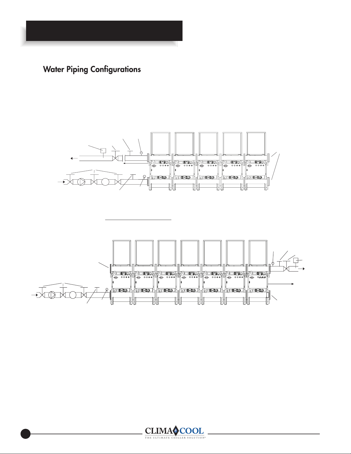
ClimaCool Water Piping Configurations
The ClimaCool® Modular Chiller -
Field Piping Direct Return - 1 to 5 Modules (Figure 1)
PressureTaps
with Shutoff Valves
& Gauges
60” Sensor Location
(Field-Installed)
PressureTap
w/Shutoff
Valve &
Gauge
Unit 1
Flow In
Flow Out
Flow Switch
Isolation Valves
Pump
Thermometer Well
Isolation Valve
Strainer
Thermometer Well
Unit 2 Unit 3 Unit 5Unit 4
Blank Off
Plates
Field Piping Reverse Return - (Preferred 1 to 5 modules) Required for 6 to 7 Modules (Figure 2)
Pressure Taps
with Shutoff Valves
Unit 1 Unit 2 Unit 3 Unit 7Unit 6Unit 5Unit 4
Blank Off
Plate
Isolation Valves
Pump
Flow In
Strainer
Thermometer Well
NOTES:
1. Figures 1 and 2 are required piping for proper water regulation and distribution through ClimaCool
PressureTap
w/Shutoff
Valve &
Gauge
®
modular chillers.
2. Module order and incoming/outgoing water fl ow as shown in both Figure 1 and 2 can be set up as either a left-to-right or
right-to-left confi guration.
3. Condenser Hydronic Circuit shown. Piping confi gurations are similar for the chilled water hydronic circuit.
4. For condenser and chilled water (evaporator) inlet/outlet location dimensions, refer to Module Dimensional Data.
5. A fl ow switch (supplied by others) is a required safety device for ClimaCool
®
modular chillers on the chilled and condenser
water circuits.
6. Maximum water fl ow rates for both evaporator and condenser water header systems in one bank of modules is 1000 GPM.
7. The chilled water piping on each module is pre-insulated at the factory with ¾” closed cell foam rubber. Insulation (3/4”)
on the chilled water header connection flanges is to be applied in the field by the installer, after the modules are bolted
together on site.
& Gauges
60” Sensor Location
(Field-Installed)
Blank Off
Plate
Thermometer Well
Isolation Valves
Flow Switch
Flow Out
10
www. cli mac ool cor p.c omwww. cli mac ool cor p.c om

®
The ClimaCool® Modular Chiller -
Figure 1 - Condenser Hydronic Circuit
ClimaCool Hydronic Refrigeration
Isolation Ball Valve (2 or 2-1/2”)
To Cooling Tower
Header
From Cooling Tower
Header
Isolation Ball Valve (2 or 2-1/2”)
Figure 2 - Chilled Water Circuit
Isolation Ball Valve (2 or 2-1/2”)
Chilled Water Inlet
Header
Pete’s Port
Service Port (3/4”)Pete’s Port
Service Port (3/4”)
Heat Exchanger
Service Port (3/4”)Pete’s Port
Refrigerant Circuit #1
Refrigerant Circuit #2
Refrigerant Circuit #1
Chilled Water Outlet
Header
Isolation Ball Valve (2 or 2-1/2”)
Cap Tube to Low Limit
Protection Thermostat
Pete’s Port
Service Port (3/4”)
Sensor Well (internal)
Heat Exchanger
NOTE: Figures 1 and 2 depict hydronic piping in each ClimaCool® chiller module.
www. cli mac ool cor p.c om
Refrigerant Circuit #2
11

®
Filling the Water System Pre-Start Up
FILLING THE WATER SYSTEMS
It is imperative that the water systems are free from
debris prior to initial operation. See the page 15 Water Treatment section for a comprehensive list of
precautions.
Filling, Purging and Leak Testing the System
After the water systems have been properly installed a visual
inspection should be made to all joints for tightness. If the
chiller is to be installed in an existing system, the cleanliness
of the existing system can be judged from the operating
conditions of the present machines. The cooling tower in
particular, should be inspected and cleaned if required. It is a
good practice to at least flush the existing system and ideally,
to acid wash the system before connecting a new chiller.
We recommend the following sequence to fill and leak check
the water systems:
1. Close all isolation valves inside each modular chiller.
2. Ensure that all drain valves are closed and that all water
main isolation valves are opened.
3. The system should be filled with clean water send through
a strainer and the system checked for leaks.
4. Once the main water lines and the chiller headers are
filled with clean water, purge and repeat the filling process
several times.
5. Open the isolation valves inside each modular chiller and
repeat the filling process, this time also checking for leaks
inside each module.
6. Following the final filling and leak checking procedure, air
should be purged from the system.
4. After several hours of operation, the strainer should be
isolated and cleaned.
5. Step 4 should be repeated until there is no more debris
being collected by the strainer.
6. Finally, open all isolation valves inside each modular
chiller and repeat step 4 and 5.
If it is not possible to install the bypass line in step 1 above,
it is recommended to drain out the initial fill of water to help
flush out debris. The chiller isolating valves should be closed
to prevent debris from being washed into the chiller as the
water drains out. Before refilling and purging the system
again, the strainers should be removed and cleaned. This
action should be repeated until there is no more debris being
collected by the strainer.
Starting the Pumps
Follow manufacturer's recommendations when staring the
pumps for the first time. The system should be checked
for leaks and air purged with the pumps in operation. The
pressure drop across the heat exchangers will give a good
indication of flow through the system (see page 34). This
should be immediately checked against the expected pressure
drop for the flow rate required. If the pressure drop begins to
fall and the flow rate is falling, this could indicate the need to
clean the strainers.
Cleaning the System
We recommend the following sequence to properly clean the
water systems:
1. If possible, install a temporary bypass line between the
supply and return water lines of both water systems prior
to cleaning the system.
2. Close all isolation valves inside each modular chiller
before engaging the main water pumps.
3. The pumps should be run with the strainer in place (see the
Starting the Pumps section for proper pump startup). All
external hydronic branches should be open to all devices in
the system.
12
www. cli mac ool cor p.c omwww. cli mac ool cor p.c om
®
Water Treatment
Table 1 - Water Quality Parameters
®
Application Parameters
WATER TREATMENT
Proper water treatment is a specialized industry. We
recommend consulting an expert in this field to analyze
the water for compliance with the water quality parameters
listed in Table 1 below. The material used in the ClimaCool
chiller exposed to the water are type 316 stainless steel,
pure copper, and carbon steel. Other materials may
exist external to the ClimaCool chiller. It is the users
responsibility to ensure these materials are compatible with
the treated water. Failure to provide proper water quality
will void the ClimaCool module's warranty.
It is further recommended to seek an experts advice to
specify the appropriate water treatment required. Typical
additives to hydronic systems include rust inhibitors,
scaling preventative, antimicrobial growth agents, and algae
preventatives. Anti-freeze solutions may also be used to
lower the freezing point.
Heavily-Contaminated Water
In such instances whereby the particulates in the water are
excessive it is recommended to install an intermediate plate
& frame heat exchanger to isolate the ClimaCool chiller
from the building water system.
Other Considerations
The following considerations are listed to help achieve
system longevity.
Cooling Tower
The cooling tower should be located away from sources of
external contaminates such as trees, dust, or grass cuttings.
Insect infiltration can be reduced by eliminating lights near
the tower. A periodic visual inspection of the tower system
should be made and contaminates removed as required.
Table 1 - Water Quality Parameters
WATER CONTAINING CONCENTRATION
Sulphate Less Than 200 ppm
pH 7.0 – 9.0
Chlorides Less Than 200 ppm
Nitrate Less Than 100 ppm
Iron Less Than 4.5 mg/l
Ammonia Less Than 2.0 mg/l
Manganese Less Than 0.1 mg/l
Dissolved Solids Less Than 1000 mg/l
CaCO3 Hardness 30 – 500 ppm
CaCO3 Alkalinity 30 – 500 ppm
CAUTION
• Excessive Chlorine, Undissolved Solids and
other improper water quality conditions
WILL DAMAGE the internal heat exchanger and
WILL VOID YOUR WARRANTY!
13
www. cli mac ool cor p.c om