

Page 1
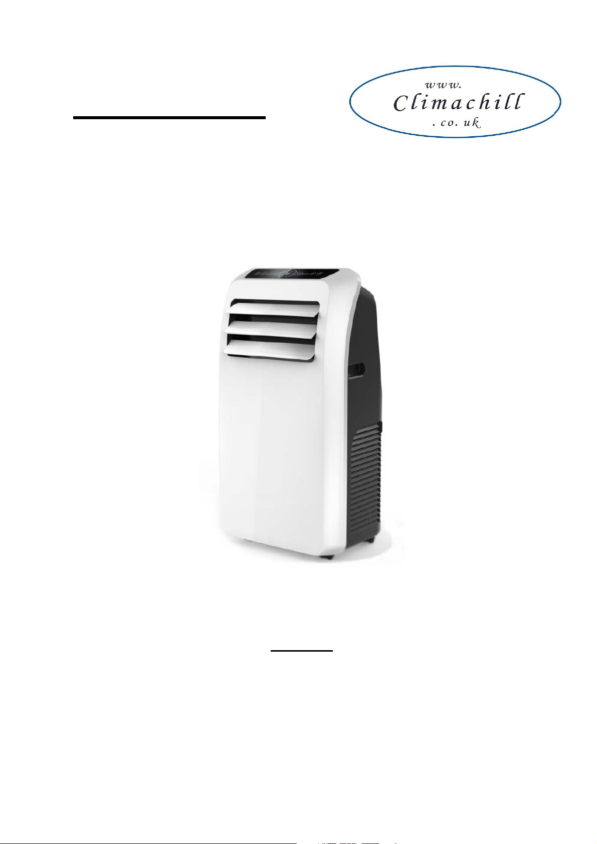
USER MANUAL
Portable Air Conditioner and Heater
With Heat Pump Technology
PAC12K
12,000btu Cool & Heat Portable Air Conditioner
Please read this manual carefully prior to operating the product.
Please keep ALL packaging for duration of Warranty Period
Page 2

TABLE OF CONTENTS
IMPORTANT SAFEGUARDS 2
INTRODUCTION / WARRANTY 4
PRODUCT DIAGRAM 5-7
INSTALLATION 8-9
OPERATION 10
WATER DRAINAGE 11
MAINTENANCE 12
TROUBLESHOOTING 12
TECHNICAL SUPPORT / CUSTOMER SERVICE CONTACT 12
SERVICE / REPAIR INFO 13
IMPORTANT SAFEGUARDS
Before installing and using your portable air conditioner and heater, it is important that you read this
owner’s manual carefully. Store this manual in a safe place for future reference.
This instruction manual is used for guidance and does not form part of a contract. It reserves the right to
make technical changes without prior notice.
1. Always place the unit on a level surface.
2. The appliance shall be installed in accordance with national wiring regulation.
3. The unit must be connected to a correctly grounded power supply. For your safety, this unit is
grounded through the power cord plug when connected to a grounded wall outlet. Do not use an
adapter plug or extension cord.
4. Do not install the unit in an area where gas leakage may occur and/or in an explosive
atmosphere.
5. Do not apply an insecticide or any type of flammable spray on the unit.
6. Confirm drainage piping is connected properly.
7. Do not start or stop the unit by inserting or pulling out the power plug.
8. Do not operate with wet hands.
9. Close supervision is necessary when the unit is used near children. The unit in not intended for
use by children.
10. Do not insert anything into the air outlet. Do not obstruct air inlet or outlet grills.
11. Do not expose skin or eyes directly to cool air for a long period of time.
12. If an abnormal odour or smoke comes out of the unit, disconnect the unit immediately and
contact a qualified service technician.
13. When opening the filter cover, do not touch the metal parts in the unit’s interior.
14. Do not immerse the unit in water or any type of liquid. Do not use the unit in the immediate
surroundings of a bath, shower, or swimming pool, or in any other steamy, wet areas.
15. When cleaning the unit, always turn the unit off and unplug the power cord.
16. Always inspect the power cord for signs of damage before use. If the power cord is damaged, it
must be replaced by the manufacturer or a qualified service technician.
17. Do not place a plant or allow a pet in the direct path of the airflow to avoid injury.
18. Do not put a stove, etc, where it would be exposed to the direct airflow. It may affect
combustion.
Page 3
19. Do not sit on the unit or place anything on it.
20. Before storing, the water must be drained from the unit and the filters cleaned.
21.
The appliance must be placed in an area without any continuously sources of ignition (for
example: open flames , gas or electrical appliances in operation).
22.
Do not puncture and do not burn.
23.
This appliance contains Y g (see rating label back of unit ) of R290 refrigerant gas.
24.
R290 is a refrigerant gas that complies with the European directives on the environment.
Do not puncture any part of the refrigerant circuit.
25.
If the appliance is installed, operated or stored in a nonventilated area, the room must be
designed to prevent to the accumulation of refrigerant leaks resulting in a risk of fire or
explosion due to ignition of the refrigerant caused by electric heaters, stoves, or other
sources of ignition.
26.
The appliance must be stored in such a way as to prevent mechanical failure.
27. Contact authorized service technician for repair or maintenance of this unit.
28. Unplug the unit if strange sounds, smell, or smoke comes from it.
General Information
Recycling
This marking indicates that this product should not be disposed with other household wastes
throughout the EU. To prevent possible harm to the environment or human health from
uncontrolled waste disposal, recycle it responsibly to promote the sustainable reuse of material
resources. To return your used device, please use the return and collection systems or contact the
retailer where the product was purchased. They can take this product for environmental safe
recycling.
Warning
The unit creates water which is collected in an internal water tank which has a rubber drain plug, it is
very unlikely but if this tank becomes damaged during transport or the rubber bung comes out then it is
possible that the unit will leak water when it is operated. Prior to use make sure the drain plug is in
place & then during first use periodically check the unit to make sure it isn’t leaking water (look at
bottom / under the unit) – during first use do not turn the unit on and leave it unattended for a long period
of time without checking.
Page 4

INTRODUCTION
Thank you for purchasing this Portable Air Conditioner and Heater. This unit is designed to improve
indoor living and working comfort by providing cooling, dehumidifying, and heating with minimal
installation.
Please complete the following information for future reference. Retain this owner’s manual with your
sales receipt as a permanent record of your purchase.
Date of Purchase: _______________________________________________________
Place of Purchase: _______________________________________________________
Invoice Number: _______________________________________________________
WARRANTY
This product comes with a 12month warranty from date of purchase (as indicated on original sales
receipt).
Please note that it is a warranty condition that ALL of the original packaging is kept for the duration of
the warranty period, (the main box can be folded flat for storage).
If you need to make a warranty claim and the unit requires returning to us then we are only able to
organise collection of the unit if it is in its original packaging (this is an insurance requirement of our
courier). Failure to keep the original packaging means we are unable to organise collection of the
product from you
Page 5
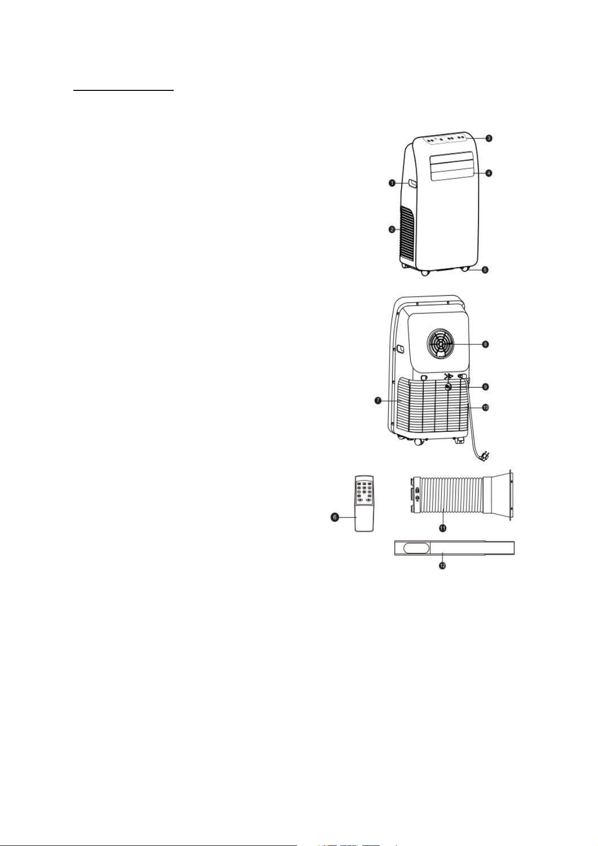
PRODUCT DIAGRAM
1.
Handle
2.
Air inlet (L)
3.
Control panel
4.
Wind guide bar
5.
Caster
6.
Remote controller
7.
Air inlet (R)
8.
Air outlet
9.
Dehumidification drainage
nozzle
10.
Air inlet grille
11.
Exhaust hose set
12.
Window kit
Page 6
High Mid Low
9
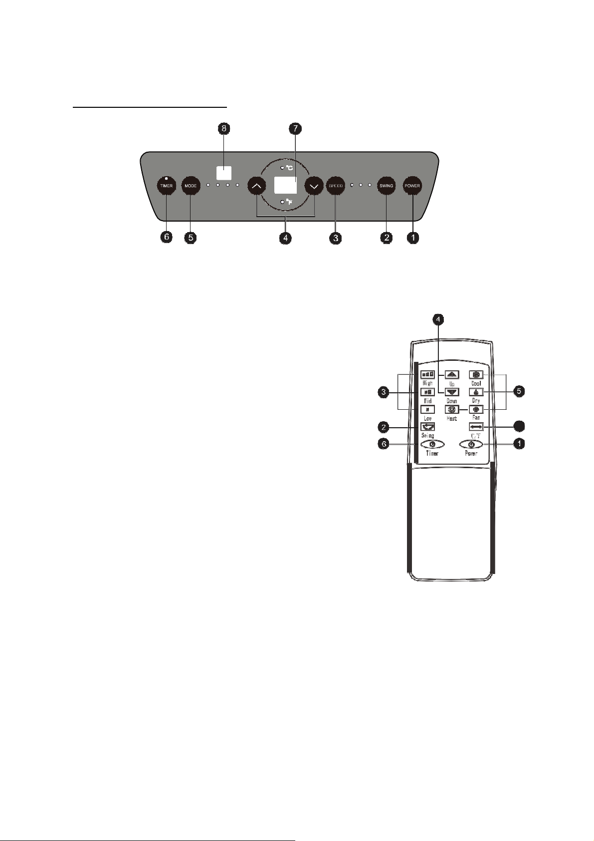
CONTROL PANEL AND DISPLAY
Cool Fan Dry Heat
1.
Power key
Press the key to turn ON/OFF the A/C.
2.
Swing key
Press this key at any time after turning on the A/C to swing
the wind guide bar automatically.
3.
Speed key
Press the key to choose high/mid/low gear wind speed.
4.
Temperature/ time adjusting key
Press the key at cooling mode to increase/reduce the
setting temperature; press it at timing mode to adjust timing
ON/OFF time; press Up and Down keys simultaneously to
switch Fahrenheit and Centigrade degree temperature.
5.
Mode key
Press the key to choose cooling, fan, dehumidification and
heating mode.
6.
Timer key
Press the key at standby mode to set ON time.
Press this key at ON mode to set OFF time.
7.
Temperature/ time display window
This window displays the adjusted temperature and time.
8.
Remote controller receiving window
This window is used to receive signal of the remote
controller.
9.
℃/℉ switching key
Press the key to switch ℃ and ℉.
Page 7
INSTALLATION
Exhausting the Air
It is necessary to use the exhaust hose when using the machine.
When in Cooling Mode hot air will be expelled out of the exhaust hose
When in Heating Mode cold air will be expelled out of the exhaust hose
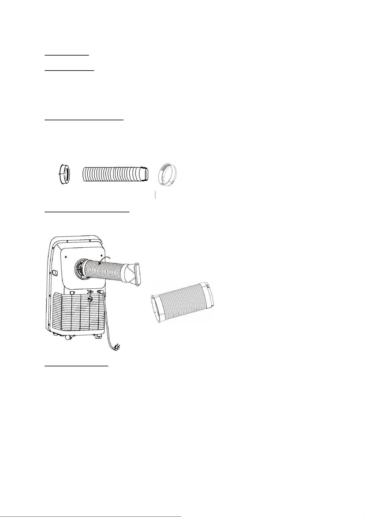
Setting Up the Exhaust Hose
Take the 3x components, extend the exhaust hose and then twist the accessories onto each end of the
hose
Attaching Exhaust Hose to Unit
With the hose assembled, insert the square adapter into the opening at the back of the air conditioner
[A1]
Venting the Exhaust Air
The exhaust hose should be kept as short and straight as possible so as to not restrict airflow of the
exhausted air.
There are 3 x options with venting the exhaust air,
1) You can make a hole in the wall and pass the exhaust hose through the hole in the wall (this
option doesn’t require a window to be slightly open)
2) You can pass the end of the exhaust hose out of a slightly open window (you can pass the
funnel attachment out of the window and then close the window onto the attachment to hold it in
place
3) You can use the sliding window kit if you have an up/down or a side opening window
Page 8
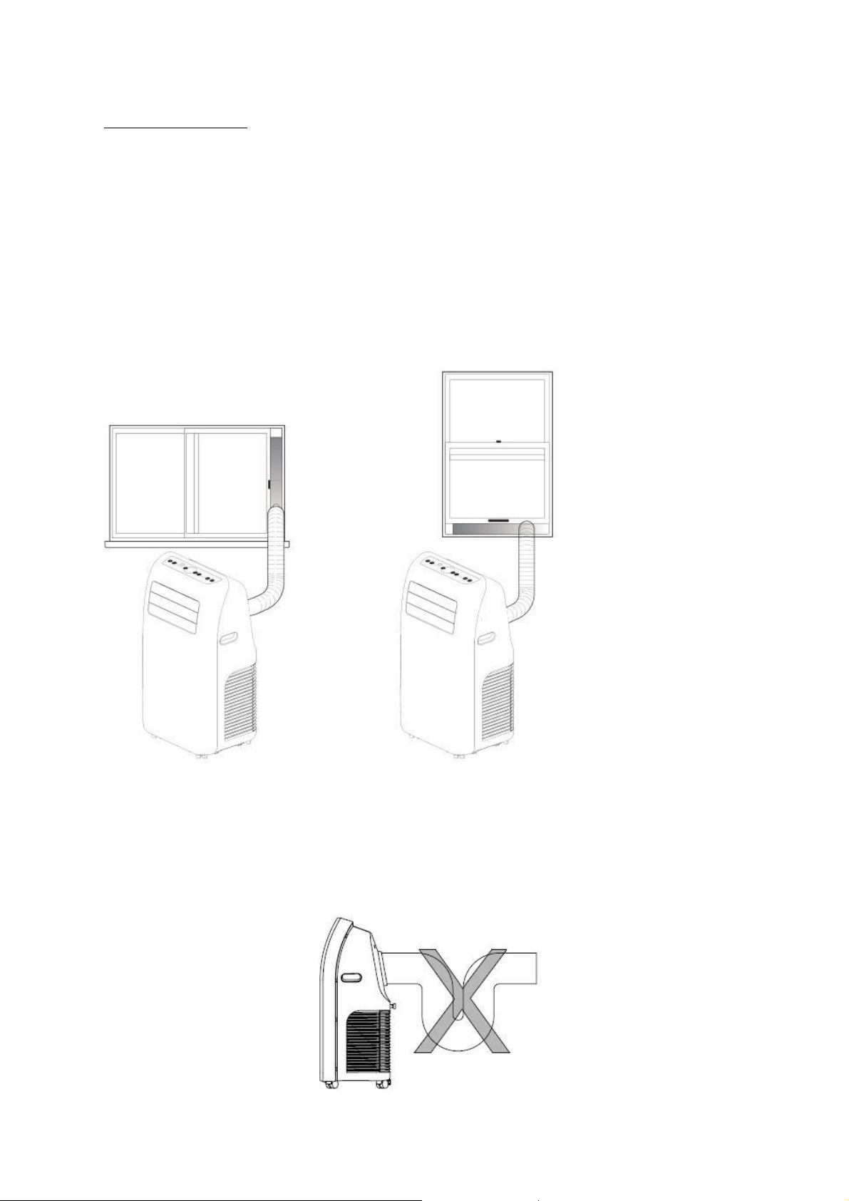
Window Kit Installation
The window kit is designed to fit into most standard vertical and horizontal windows. However, it may be
necessary to modify some aspects of the installation process for certain window types.
1. Open the window or sliding door and adjust the length of the window kit to fit the opening. Mark
and cut down a single panel of the window kit if necessary.
2. Place the window kit between the window and the window frame as shown in the images to the
right. Close the window onto the window kit to form a tight seal.
3. Attach the exhaust duct adapter to the window kit. Tabs located on the adapter will lock into place
securing the adapter to the window kit.
Incorrect installation
It’s important to keep the exhaust duct smooth. Incorrect installation will affect work of
the A/C.
Prevent the exhaust duct from seriously bending.
Ensure air can flow smoothly in the duct.
Page 9
OPERATION
Before Use
• Check that the Exhaust Hose has been mounted properly (see ‘Installation’ section). If the
exhaust Hose is not correctly used, hot air will blow back into the room you are trying cool
• Check that the drain plug at the bottom rear of the unit is securely plugged in, to prevent water
leaks (see page 9 – Water Drainage)
• Check that the local mains power matches that shown on the rating label of the unit
• Check that the location of the unit is suitable (flat, stable surface; away from sources water /
heat)
• If the unit has recently been transported, let it stand for 6 hours to allow the compress contents
to settle
Cooling mode
When the A/C enters cooling mode automatically or cooling mode is selected after
power ON, the cooling indicator lamp lights up.
Press Up/Down key to adjust setting temperature (16℃~30℃).
Press Speed key to choose High/Mid/Low speed.
Fan mode
When pressing mode key or choosing Fan mode by pressing the remote controller,
the wind indicator lamp lights up.
Press Speed key to choose High/Mid/Low speed.
Temperature can’t be set.
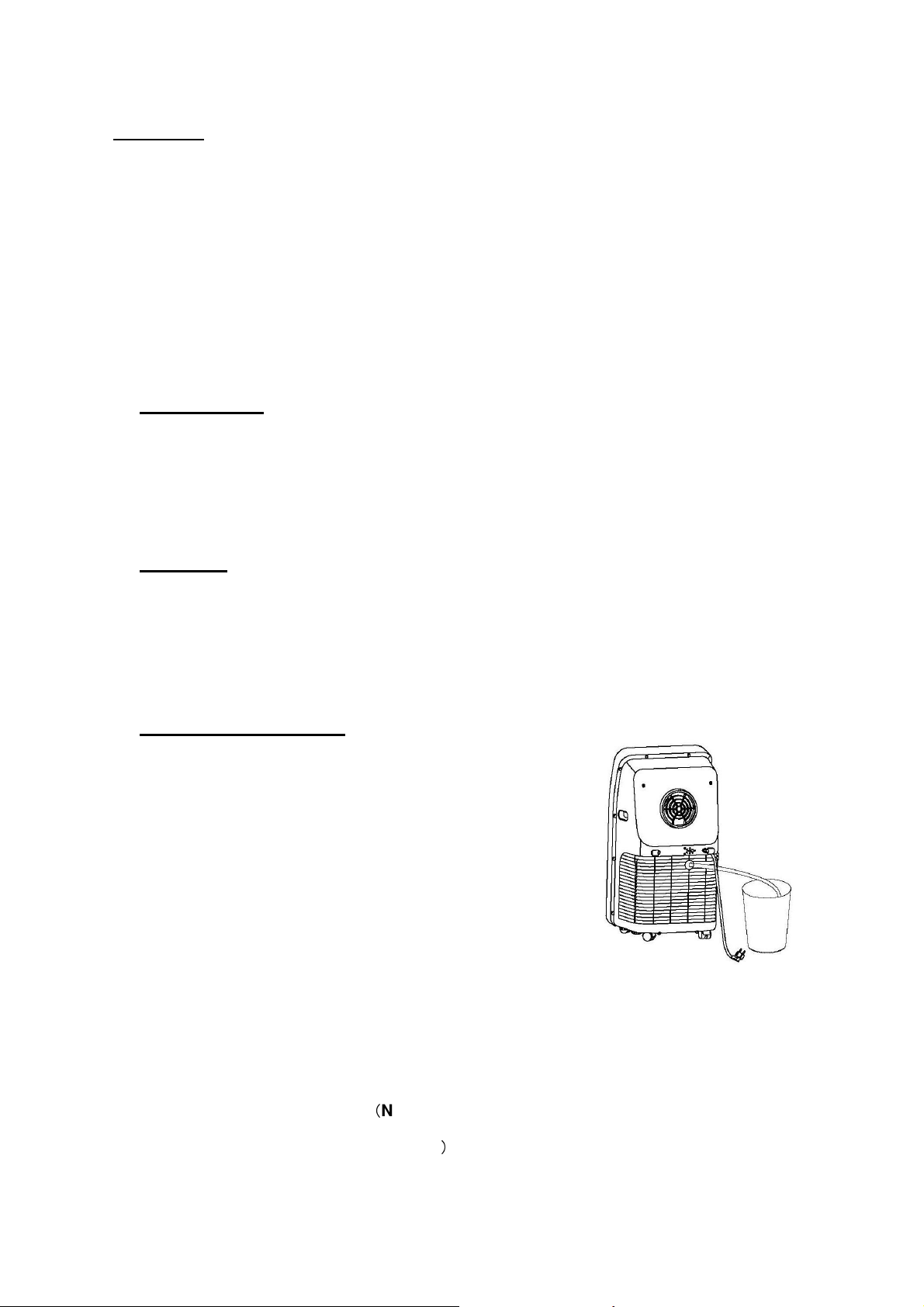
Dehumidification mode
When pressing mode key or choosing dehumidification
mode by pressing the remote controller, the
dehumidification indicator lamp lights up.
Remove the dehumidification water wedge, insert water
manifold, place the other end of the water manifold into
the water vessel or drainage passage, as shown in the
right figure.
After entering the dehumidification mode, if room
tempearture≥17℃ (62℉), the compressor is ON. Then
control as follows: when room temperature ≤15℃ (59℉),
the compressor is OFF; when temperature increases to room temperature≥15℃, the
compressor is started again (in order to protect the compressor, it will be restarted 3min.
later).
In dehumidification mode, the fan is defaulted to run at low speed, and wind speed
can’t be adjusted.
Temperature can’t be set. (Note : when use dehumidify function, should remove
exit pipe components, otherwise, it will cause worse dehumidify performance,
)
and appear “FL” water full alarm
Page 10
Heating mode
When pressing mode key or choosing heating mode by pressing the remote
controller, the heating indicator lamp lights up.
Press Up/Down key to adjust setting temperature (16℃~30℃).
Press Speed key to choose High/Mid/Low speed.
If room is too cold fan speed may not alter, machine will set the fan speed until the room is
warmer
Timer mode
In standby state, press the Timer key to set ON time. Press Up and Down keys to set
ON time (1~24H), and the timer indicator lamp lights up.
In ON state, pressure the timer key to set OFF time. Press Up and Down keys to set
OFF time (1~24H), and the timer indicator lamp lights up.
WATER DRAINAGE
This product is equipped with automatic water vaporization system. The condenser
is cooled with the circulating of condensing water, so as to improve cooling
efficiency and save energy.
If the internal vessel is full of water, the display screen will
display “FL”, and the compressor stops working
automatically. After power off, unscrew the water cover,
pull out the water wedge to drain off water, and it will
become normal after being restarted.
NOTE: In heating mode, the unit will also create water which needs emptying from the machine.
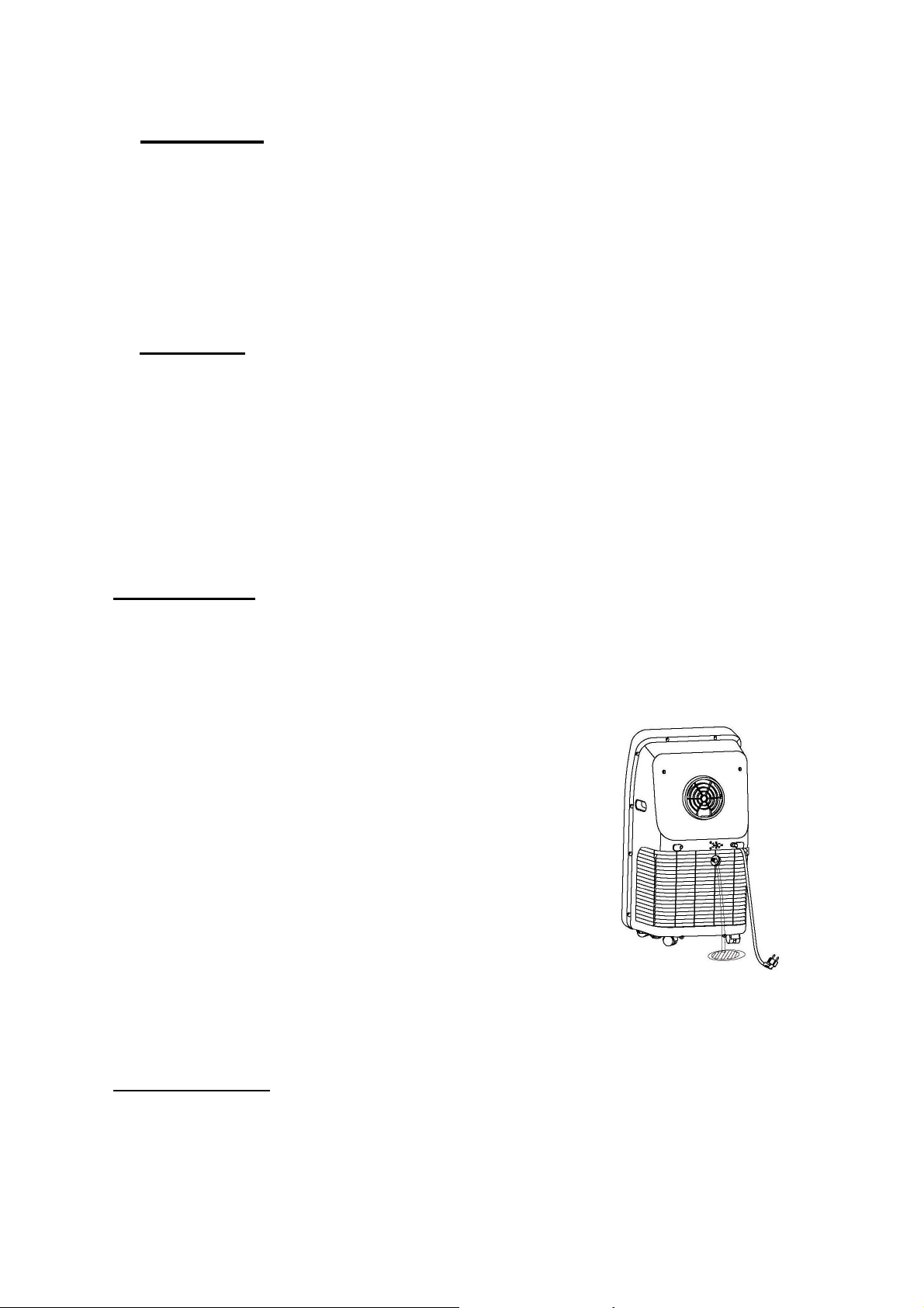
Continuous Drainage
You can of course set the unit up for continuous drainage thus negating the need to empty water
from the machine. To do this remove the rubber bung from the unit and attach the drain hose to
the unit, then drain the water into a container (be careful that it doesn’t overspill from the container)
Page 11
MAINTENANCE & CLEANING
1) Before cleaning, be sure to disconnect the unit from any electric supply outlet;
2) Do not use gasoline or other chemicals to clean the unit;
3) Do not wash the unit directly;
4) If the conditioner is damaged, please contact the dealer or repair shop
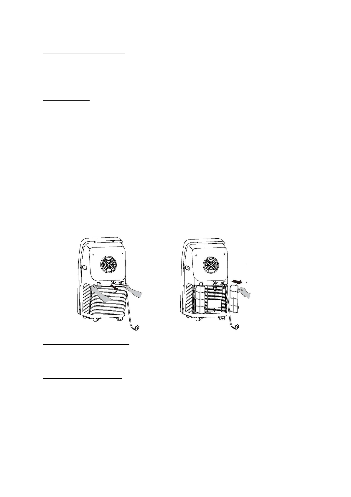
Cleaning Air Filter
If the air filter becomes clogged with dust/dirt the unit will not function properly, the air filter should be
cleaned once every two weeks.
• Open the air inlet grille and take off air filter.
• Clean the air filter with a brush (brush the dust/dirt off the filter)
• If very dirty use a neutral detergent in lukewarm water and dry in the shade.
• Put air filter back into unit & close the air inlet grille.
• Wash the filter screen once every two weeks. If it is blocked by dust, efficiency of the A/C will be
reduced.
• Take out the air inlet grille and pull out the filter screen at both sides according to the direction
shown in the following figures.
• Put the filter screen into the warm water (about 40℃) added with neutral detergent,
dry it at a shady place after cleaning.
Clean the Air-conditioner Surface
First clean the surface with a neutral detergent and wet cloth, and then wipe it with a dry cloth.
END OF SEASON STORAGE
Before storing the machine be sure to drain all of the water from the machine (see water drainage
section)
Page 12
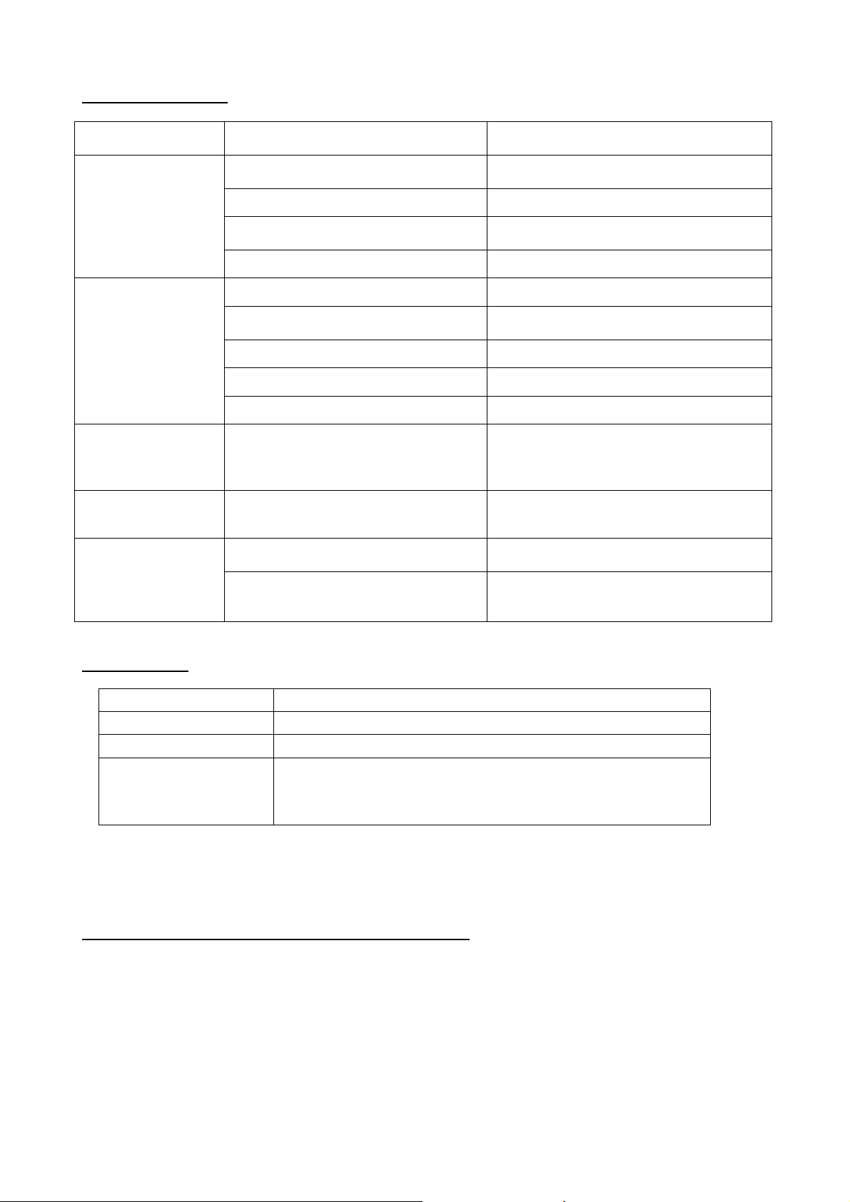
TROUBLESHOOTING
PROBLEM POSSIBLE CAUSE REMEDY
Securely plug the power cord into the wall
outlet.
Empty the water container.
Move the heat source.
Restart the unit at lower room temeprature
Place the unit on a level surface.
Use a proper power source.
Position the exhaust hose correctly and
keep the exhaust hose straight as
possible.
Unit does not
operate or only runs
in fan mode.
Cooling efficiency is
not satisfactory.
Auto power off in
Heating Mode
Unit is noisy or
vibrates.
The unit starts and
stops frequently.
Is the unit plugged in?
Is the main power supply on? Re-establish the main power supply.
Is the water container full indicator light
on?
Is the timer set? Change timer settings.
Is the air inlet or outlet blocked? Clear the blocking.
Is there any other heat source in the
room?
Are the air filters dirty? Clean the air filters.
Is the temperature setting suitable? Change the temperature setting.
Is the fan speed set at low? Increase the fan speed.
Heating Protection, when the
temperature at the air outlet exceeds
70C, the unit will power off
automatically
Is the machine positioned unevenly on
a level surface?
Is the voltage from the power source
correct?
Is the exhaust hose positioned
incorrectly?
ERROR CODES
Error-detecting code Multi-functional defection
E1 Error of the coil’s temperature sensor
E2 Error of indoor temperature sensor
E4
Anti-freezing protection: temperature of the coil is too low and
the whole A/C is off. When temperature excesses 8℃, the
protection is released and previous working state is recovered.
If any other error codes are displayed please contact the following via email [email protected]
TECHNICAL SUPPORT / CUSTOMER SERVICE CONTACT
If you require Technical Support or Customer Service please contact us in the following way: -
Email: [email protected]
Telephone: 01273 803820
12/19
Page 13

13/19
Service / Repair Information
Warnings
Any person who is involved with working on or breaking into a refrigerant a refrigerant circuit should
hold a current valid certificate from an industry-accredited assessment authority. Which authorizes
their competence to handle refrigerants safety in accordance with an industry recognized
assessment specifications.
Remember the environment when disposing of packaging around the appliance and when the
appliance
has reached its by date.
A warning that the appliance shall be stored in a well-ventilated area where the size corresponds to
the
room area as specified for operation.
The appliance shall be stored so as to prevent mechanical damage from occurring.
Information for spaces where refrigerant pipes are allowed, including statements
• that the installation of pipe-work shall be kept to a minimum;
• that pipe-work shall be protected from physical damage and, in the case of flammable refrigerants,
shall not be installed in an unventilated space;
• that compliance with national gas regulations shall be observed;
• that mechanical connections shall be accessible for maintenance purposes;
• that, for appliances containing flammable refrigerants, the minimum floor area of the room shall be
mentioned in the form of a table or a single figure without reference to a formula;
A warning to keep any required ventilation openings clear of obstruction;
A notice that servicing shall be performed only as recommended by the manufacturer;
A warning that ducts connected to an appliance shall not contain a potential ignition source;
When the portable air conditioner or dehumidifier is turned on, the fan can work continuously stable
under normal conditions to provide the minimum air volume of 100m3/h even when the compressor
is closed due to the temperature controller.
Do not pierce or burn.
Use only implements recommended by the manufacturer for defrosting or cleaning
Do not perforate any of the components in the refrigerant circuit. Refrigerant gas may be odourless
Use care when storing the appliance to prevent mechanical faults.
Only persons authorized by an accredited agency certifying their competence to handle refrigerants
in compliance with sector legislation should work on refrigerant circuit.
All repairs must be carried out in accordance with the manufacturer’s recommendations.
Maintenance and repairs requiring the assistance of other qualified personnel must be carried out
under
the supervision of specialists in the use of inflammable refrigerants.
Do not perforate any of the components in the refrigerant circuit. Refrigerant gas may be odourless
Page 14
14/19
Additional warning for appliance with R290 refrigerant gas
(refer to the rating plate for the type of refrigerant gas used)
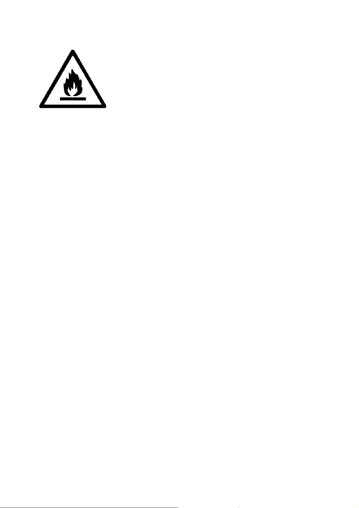
CAUTION ON FIRE
READ THE MAUAL CAREFULLY BEFORE USING THE APPLIANCE
R290 refrigerant gas complies with European environmental directives.
This appliance contains approximately 245 g of R290 refrigerant gas
Appliance shall be installed, operated and stored in a room with a floor area larger than 12 m2.
Page 15

15/19
Instruction, Repairing Appliances Containing R 290
1. Checks to the area
Prior to beginning work on systems containing flammable refrigerants, safety checks
are necessary to ensure that the risk of ignition is minimised. For repair to the
refrigerating system, the following precaution shall be completed prior to conducting
work on the system.
2. Work procedure
Work shall be undertaken under a controlled procedure so as to minimise the risk of a
flammable gas or vapour being present while the work is being performed.
3. General work area
All maintenance staff and others working in the local area shall be instructed on the nature
of work being carried out. Work in confined spaces shall be avoided.
4. Checking for presence of refrigerant
The area shall be checked with an appropriate refrigerant detector prior to and during work,
to ensure the technician is aware of potentially toxic or flammable atmospheres. Ensure that
the leak detection equipment being used is suitable for use with all applicable refrigerants,
i.e. non-sparking, adequately sealed or intrinsically safe.
5. Presence of fire extinguisher
If any hot work is to be conducted on the refrigerating equipment or any associated
parts, appropriate fire extinguishing equipment shall be available to hand. Have a dry
powder or CO2 fire extinguisher adjacent to the charging area.
6. No ignition sources
No person carrying out work in relation to a refrigerating system which involves
exposing any pipe work shall use any sources of ignition in such a manner that it may
lead to the risk of fire or explosion. All possible ignition sources, including cigarette
smoking, should be kept sufficiently far away from the site of installation, repairing,
removing and disposal, during which refrigerant can possibly be released to the
surrounding space. Prior to work taking place, the area around the equipment is to be
surveyed to make sure that there are no flammable hazards or ignition risks. “No
Smoking” signs shall be displayed.
7. Ventilated area
Ensure that the area is in the open or that it is adequately ventilated before breaking
into the system or conducting any hot work. A degree of ventilation shall continue
during the period that the work is carried out. The ventilation should safely disperse any
released refrigerant and preferably expel it externally into the atmosphere.
8. Checks to the refrigerating equipment
Where electrical components are being changed, they shall be fit for the purpose and to
the correct specification. At all times the manufacturer’s maintenance and service
guidelines shall be followed. If in doubt, consult the manufacturer’s technical
department for assistance.
The following checks shall be applied to installations using flammable refrigerants:
–
the actual refrigerant charge is in accordance with the room size within which the
refrigerant containing parts are installed;
–
the ventilation machinery and outlets are operating adequately and are not obstructed;
–
if an indirect refrigerating circuit is being used, the secondary circuit shall be
checked for the presence of refrigerant;
Page 16

16/19
–
marking to the equipment continues to be visible and legible. Markings and signs
that are illegible shall be corrected;
–
refrigerating pipe or components are installed in a position where they are unlikely to
be exposed to any substance which may corrode refrigerant containing components,
unless the components are constructed of materials which are inherently resistant to
being corroded or are suitably protected against being so corroded.
9. Checks to electrical devices
Repair and maintenance to electrical components shall include initial safety checks and
component inspection procedures. If a fault exists that could compromise safety, then no
electrical supply shall be connected to the circuit until it is satisfactorily dealt with. If the fault
cannot be corrected immediately but it is necessary to continue operation, an adequate
temporary solution shall be used. This shall be reported to the owner of the equipment so all
parties are advised.
Initial safety checks shall include:
• that capacitors are discharged: this shall be done in a safe manner to avoid
possibility of sparking;
• that no live electrical components and wiring are exposed while charging,
recovering or purging the system;
• that there is continuity of earth bonding.
10. REPAIRS TO SEALED COMPONENTS
During repairs to sealed components, all electrical supplies shall be disconnected from
the equipment being worked upon prior to any removal of sealed covers, etc. If it is
absolutely necessary to have an electrical supply to equipment during servicing, then a
permanently operating form of leak detection shall be located at the most critical point
to warn of a potentially hazardous situation.
Particular attention shall be paid to the following to ensure that by working on electrical
components, the casing is not altered in such a way that the level of protection is
affected. This shall include damage to cables, excessive number of connections,
terminals not made to original specification, damage to seals, incorrect fitting of glands,
etc.
Ensure that the apparatus is mounted securely.
Ensure that seals or sealing materials have not degraded to the point that they no
longer serve the purpose of preventing the ingress of flammable atmospheres.
Replacement parts shall be in accordance with the manufacturer’s specifications.
11. REPAIR TO INTRINSICALLY SAFE COMPONENTS
Do not apply any permanent inductive or capacitance loads to the circuit without ensuring
that this will not exceed the permissible voltage and current permitted for the equipment in
use.
Intrinsically safe components are the only types that can be worked on while live in the
presence of a flammable atmosphere. The test apparatus shall be at the correct rating.
Replace components only with parts specified by the manufacturer. Other parts may
result in the ignition of refrigerant in the atmosphere from a leak.
12. CABLING
Page 17

17/19
Check that cabling will not be subject to wear, corrosion, excessive pressure, vibration,
sharp edges or any other adverse environmental effects. The check shall also take into
account the effects of aging or continual vibration from sources such as compressors or
fans.
13. DETECTION OF FLAMMABLE REFRIGERANTS
Under no circumstances shall potential sources of ignition be used in the searching for
or detection of refrigerant leaks. A halide torch (or any other detector using a naked
flame) shall not be used.
14. REMOVAL AND EVACUATION
When breaking into the refrigerant circuit to make repairs – or for any other purpose –
conventional procedures shall be used. However, for flammable refrigerants it is
important that best practice is followed since flammability is a consideration. The
following procedure shall be adhered to:
• remove refrigerant;
• purge the circuit with inert gas;
• evacuate;
• purge with inert gas;
• open the circuit by cutting or brazing.
The refrigerant charge shall be recovered into the correct recovery cylinders. For
appliances containing flammable refrigerants the system shall be purged with
oxygen-free nitrogen to render the appliance safe for flammable refrigerants. This
process may need to be repeated several times. Compressed air or oxygen shall not be
used for purging refrigerant systems.
For appliances containing flammable refrigerants, refrigerants purging shall be
achieved by breaking the vacuum in the system with oxygen-free nitrogen and
continuing to fill until the working pressure is achieved, then venting to atmosphere,
and finally pulling down to a vacuum. This process shall be repeated until no refrigerant
is within the system. When the final oxygen-free nitrogen charge is used, the system
shall be vented down to atmospheric pressure to enable work to take place. This
operation is absolutely vital if brazing operations on the pipe-work are to take place.
Ensure that the outlet for the vacuum pump is not close to any potential ignition sources and that
ventilation is available.
15. CHARGING PROCEDURES
In addition to conventional charging procedures, the following requirements shall be followed.
• Ensure that contamination of different refrigerants does not occur when using
charging equipment. Hoses or lines shall be as short as possible to minimise the
amount of refrigerant contained in them.
• Cylinders shall be kept in an appropriate position according to the instructions.
• Ensure that the refrigerating system is earthed prior to charging the system with
refrigerant.
• Label the system when charging is complete (if not already).
• Extreme care shall be taken not to overfill the refrigerating system.
Prior to recharging the system, it shall be pressure-tested with the appropriate purging
gas. The system shall be leak-tested on completion of charging but prior to
commissioning. A follow up leak test shall be carried out prior to leaving the site.
16. DECOMMISSIONING
Page 18

18/19
Before carrying out this procedure, it is essential that the technician is completely
familiar with the equipment and all its detail. It is recommended good practice that all
refrigerants are recovered safely. Prior to the task being carried out, an oil and
refrigerant sample shall be taken in case analysis is required prior to re-use of
recovered refrigerant. It is essential that electrical power is available before the task is
commenced.
a)
Become familiar with the equipment and its operation.
b)
Isolate system electrically.
c)
Before attempting the procedure, ensure that:
• mechanical handling equipment is available, if required, for handling refrigerant
cylinders;
• all personal protective equipment is available and being used correctly;
• the recovery process is supervised at all times by a competent person;
• recovery equipment and cylinders conform to the appropriate standards.
d)
Pump down refrigerant system, if possible.
e)
If a vacuum is not possible, make a manifold so that refrigerant can be removed
from various parts of the system.
f)
Make sure that cylinder is situated on the scales before recovery takes place.
g)
Start the recovery machine and operate in accordance with instructions.
h)
Do not overfill cylinders (no more than 80 % volume liquid charge).
i)
Do not exceed the maximum working pressure of the cylinder, even temporarily.
j)
When the cylinders have been filled correctly and the process completed, make
sure that the cylinders and the equipment are removed from site promptly and all
isolation valves on the equipment are closed off.
k)
Recovered refrigerant shall not be charged into another refrigerating system
unless it has been cleaned and checked.
17. LABELLING
Equipment shall be labelled stating that it has been de-commissioned and emptied of
refrigerant. The label shall be dated and signed. For appliances containing flammable
refrigerants, ensure that there are labels on the equipment stating the equipment
contains flammable refrigerant.
18. RECOVERY
When removing refrigerant from a system, either for servicing or decommissioning, it is
recommended good practice that all refrigerants are removed safely.
When transferring refrigerant into cylinders, ensure that only appropriate refrigerant
recovery cylinders are employed. Ensure that the correct number of cylinders for
holding the total system charge is available. All cylinders to be used are designated for
the recovered refrigerant and labelled for that refrigerant (i.e. special cylinders for the
recovery of refrigerant). Cylinders shall be complete with pressure-relief valve and
associated shut-off valves in good working order. Empty recovery cylinders are
evacuated and, if possible, cooled before recovery occurs.
The recovery equipment shall be in good working order with a set of instructions
concerning the equipment that is at hand and shall be suitable for the recovery of all
appropriate refrigerants including, when applicable, flammable refrigerants. In
addition, a set of calibrated weighing scales shall be available and in good working
order. Hoses shall be complete with leak-free disconnect couplings and in good
condition. Before using the recovery machine, check that it is in satisfactory working
order, has been properly maintained and that any associated electrical components are
sealed to prevent ignition in the event of a refrigerant release. Consult manufacturer if
in doubt.
Page 19

19/19
The recovered refrigerant shall be returned to the refrigerant supplier in the correct
recovery cylinder, and the relevant waste transfer note arranged. Do not mix
refrigerants in recovery units and especially not in cylinders.
If compressors or compressor oils are to be removed, ensure that they have been
evacuated to an acceptable level to make certain that flammable refrigerant does
not remain within the lubricant. The evacuation process shall be carried out prior to
returning the compressor to the suppliers. Only electric heating to the compressor body
shall be employed to accelerate this process. When oil is drained from a system, it shall
be carried out safely.
 Loading...