

ClimaCheck PA Pro III online Installation Manual

ClimaCheck Sweden AB, Box 46, SE-131 06 Nacka, Sweden
Visiting address: Gamla Värmdövägen 6, SE-131 37 Nacka Sweden
Tel.: +46 (0)8-50 255 250, Email: info@climacheck.com
Web: www.climacheck.com
Performance Analyser
ClimaCheck PA Pro III online
Installation Manual
2018-03-16
.

Installation Manual PA Pro III online – 2018-03-16 Page 2 of 30
Safety Precautions
Read the instruction manuals for all relevant equipment carefully before
starting to use ClimaCheck Performance Analysing systems.
ClimaCheck PA Pro III is a measuring and analysing system developed to give
detailed evaluation of refrigeration, air-conditioning and heat-pump systems in
development laboratories, production tests and in the field.
If equipment is used in a way not specified by producer the protection and safety provided may be
impaired.
Certifications/licenses are required in most countries for activities related to electrical systems,
pressurised systems and systems charged with refrigerants that have environmental impacts
and/or flammability.
ClimaCheck products are only intended for use by competent technicians/engineers complying with
local requirements for certifications/licenses.
Any work with electricity, pressurised systems or refrigerant involves potential dangers to human
health and system integrity if not conducted with caution. Always inspect the equipment for
damaged cables or other components before use. For many installations loss of product or
disturbances in operation incurs high costs. ClimaCheck assumes no responsibility for injuries or
costs that may occur as a result of failures in connection with measurements. The user must
evaluate whether an inspection can be carried out without risk of injury and/or damage.
Measurements should only be carried out when it can be done under safe working conditions and
without risks.

Installation Manual PA Pro III online – 2018-03-16 Page 3 of 30
Table of Contents
Safety Precautions ............................................................................................................... 2
1 Introduction .................................................................................................................. 5
2 Handling and safety ....................................................................................................... 6
3 Required documents and equipment ................................................................................ 7
4 Connection of power measurement .................................................................................. 8
4.1 Motor configurations ................................................................................................. 8
4.1.1 Part Winding ..................................................................................................... 8
4.1.2 Y/D (Star/Delta) ................................................................................................ 8
4.2 Systems with inverter ............................................................................................... 9
4.3 Differential protection ............................................................................................... 9
5 Connection of sensors ................................................................................................... 10
5.1 Mounting of pressure transmitters/transducers ........................................................... 10
5.2 Mounting temperature sensors .................................................................................. 10
5.2.1 Required insulation ........................................................................................... 10
5.2.2 Compensating for changes in temperature sensor cable length ............................... 11
5.3 1-wire temperature sensors ...................................................................................... 11
6 ClimaCheck PA Pro III Hardware ..................................................................................... 13
6.1 LED indicators ......................................................................................................... 13
6.2 Display ................................................................................................................... 14
6.3 Start ...................................................................................................................... 15
6.4 Menus .................................................................................................................... 16
6.5 Monitor .................................................................................................................. 16
6.5.1 View all values ................................................................................................. 17
6.5.2 Send interval / Intense send .............................................................................. 17
6.5.3 Signal level ...................................................................................................... 17
6.6 Setup ..................................................................................................................... 17
6.6.1 Reload configuration ......................................................................................... 17
6.6.2 Reboot ............................................................................................................ 18
7 Configuration of 1-wire sensors ...................................................................................... 19
7.1 Connecting sensors.................................................................................................. 19
7.2 Replace a 1-wire senor ............................................................................................. 19
7.3 Clear all 1-wire sensors ............................................................................................ 19
8 Configuration of PA Pro III ............................................................................................. 21
8.1 Change analog input mode (mA/V) ............................................................................ 21
8.2 Change communication mode ................................................................................... 21
9 Configuration of Power Meter EM24 ................................................................................. 23
9.1 Change CT-ratio configuration ................................................................................... 23
9.2 Change Modbus address ........................................................................................... 23
10 Configuration of Power Meter EM210 ............................................................................... 24
10.1 Change CT type configuration ................................................................................... 24
10.2 Change Modbus address ........................................................................................... 24
11 Configuration of IO module R560 .................................................................................... 25
11.1 Change Modbus address ........................................................................................... 25
11.2 Change Analog input mode ....................................................................................... 25
12 Troubleshooting ............................................................................................................ 26
12.1 Pressure readings .................................................................................................... 26
12.1.1 Required tools and spare parts ........................................................................... 26
12.1.2 Transmitter type ............................................................................................... 26
12.1.3 Supply voltage ................................................................................................. 26
12.1.4 Pressure signal ................................................................................................. 27
12.2 Temperature readings with PT1000 sensors ................................................................ 27
12.2.1 Required tools and spare parts ........................................................................... 27
12.2.2 Common issues ................................................................................................ 28
12.2.3 Temperature-resistance table ............................................................................. 28

Installation Manual PA Pro III online – 2018-03-16 Page 4 of 30
12.3 Temperature readings with 1-wire sensors ................................................................. 28
12.4 Power measurement ................................................................................................ 29
12.4.1 Supply voltage ................................................................................................. 29
12.4.2 Communication ................................................................................................ 29
12.4.3 Measurement ................................................................................................... 29
Note: Areas with red side marking are related to certification and should not be changed without
new date here log on changes are kept separately. Current date of changes is 2018-03-16.

Installation Manual PA Pro III online – 2018-03-16 Page 5 of 30
1 Introduction
ClimaCheck1 is a measuring and analysing system developed to give detailed evaluation of
refrigeration, air-conditioning and heat-pump systems in development laboratories, production
tests and in the field.
The method is based on measurements in the refrigeration circuit and does not require any fixed
installation of metering equipment in the system. The advantages of easy connection, immediate
and detailed information makes the ClimaCheck method superior for evaluating all refrigeration,
air-conditioning and heat pump systems.
An increased focus on energy efficiency can be seen in the EU Directive 2002/91/Ec on
the Energy Performance of Building and several other requirements on energy
performance on other markets. This directive requires annual inspections with
verifications of energy efficiency of all AC systems with more that 12 kW rated capacity.
Measuring with ClimaCheck gives and excellent foundation for performance inspections.
The ClimaCheck Performance Analysing method allows complete analysis of energy performance
as well as presenting all information to validate the individual components and their optimization
without the requirement of any fixed equipment making it possible to immediately identify and
locate any deficiencies in the system. The method was patented in 1986 and has since been used
in Sweden and internationally in the Product ETM 1500, ETM 2000, ClimaCheck PA 8:7 and now
ClimaCheck PA Pro.
The server based monitoring software is constantly logging the performance of the system and
uses the globally accepted equations for refrigerant properties in RefProp established by NIST
(National Institute of Standards and Technologies in USA). Anyone with the user name and
password can log in to the system from an Internet connected PC as well as have the server send
alarms when important parameters fall outside of their specified ranges.
The ClimaCheck method is suitable for almost all compressor-based refrigeration processes. All
suction or discharge gas cooled hermetic and semi hermetic compressors can be fully evaluated
without any compressor or system specific information. For open compressors the electrical motor
efficiency is given as input and for compressors with external cooling of air, water, oil or liquid
injection information on the cooling need to be entered to give a full capacity and COP accuracy.
For many types of systems data on compressor cooling are well known and necessary parameters
are known. ClimaCheck Specialists should be consulted to give advice on non-standard systems.

Installation Manual PA Pro III online – 2018-03-16 Page 6 of 30
2 Handling and safety
To ensure safe installation and operation the following instructions must be followed carefully:
- The equipment should be powered by either 90 – 264 V AC at 47 – 64 Hz or 120 – 370 V
DC. The maximum power consumption of the system is 25 W.
- An easily reachable external switch for breaking power to the installation has to be
available.
- Operating temperature range for the equipment is -20 to +50 °C.
- Operating humidity is R.H. 0 – 90 % non-condensing.
- Maximum operating altitude: 2000 m
- The equipment is designed for a maximum of Pollution Degree 2.
- The equipment enclosures have not been tested for UV-resistance and are thus not
approved for outdoor use.
- The enclosure must be mounted with at least three sides having a minimum clearance of
10 cm. The front must have a clearance of at least 30 cm.
- Burned out fuses must be replaced in accordance to the table below. Use only UL/CSA
approved fuses.
Marking on
fuse holder
Fuse type
L
T 1 A L, 250 V
L1
T 500 mA L, 250 V
L2
T 500 mA L, 250 V
L3
T 500 mA L, 250 V
- See section 4 for important safety instructions when connecting the power measurement.
- For all electrical wires not included with the equipment, use UL1569 AWG20 or better. Not
that special considerations should be taken for the wiring of the power meters, see section
4.
- The standard enclosure is marked with protection class IP55, but the protection of the final
installation may be lower depending on several factors. ClimaCheck do not guarantee a
certain protection class.
- If the instructions in this section and the rest of the manual are not observed, the
protection provided by the equipment may be impaired.

Installation Manual PA Pro III online – 2018-03-16 Page 7 of 30
3 Required documents and equipment
In addition to this instruction a number of documents and equipment is required in order to
successfully complete the installation:
- Flow chart of the system with sensor placement, supplied with the attached configuration
document.
- Wiring diagram of the system, supplied with the attached configuration document.
- Small flathead screwdriver 2.5 x 0.5 mm.
- Aluminium tape.
- Insulation tape.
- A number of standard tools depending on the nature of the installation.

Installation Manual PA Pro III online – 2018-03-16 Page 8 of 30
4 Connection of power measurement
Important!
Improper use of ClimaCheck power meters may cause high voltage
build up that can be dangerous both for equipment and operators. Adhere to the
practices below to avoid this:
- Always connect the CTs to the power meter before they are attached around a live
wire.
- Always remove the CTs from the live wire before the cables to the power meter
are disconnected.
- Incorrect connection of voltage between phase and neutral will damage the
equipment.
- Never use the CTs on uninsulated wires or rails.
In addition, follow the steps below to assure proper power and energy readings:
- It is important to only measure the power to the compressor. Make sure the measurement
is done after the point where circulation pumps and fans are connected.
- Make sure that the voltage and current for each phase corresponds with the markings on
the measuring equipment and that the arrow on the current clamps are pointing in the
direction of the current.
- Make sure that the CTs are completely closed and that the contact areas are clean.
- Check that the connections are correct by reading the voltage, current and power on the
display of the power meter. If you find a problem remove the clamps and attach L1
followed by a control and the repeat the process for L2 and L3.
4.1 Motor configurations
Power measurements require good understanding of the electrical layout of the plant.
It is for example necessary to identify if a three-phase motor is part winding or Y/D (Star/Delta)
and connect accordingly.
4.1.1 Part Winding
Part winding means that the motor has two separate windings and the total current to these should
be measured. This can be done in several ways depending on the physical restrictions of cables and
CTs.
- Preferred choice is to measure before the contactors where the total current runs through
one lead. This can sometimes be physically impossible.
- One alternative is to put clamps around both L1 cables after the contactor or in the
connection box on the compressor if this can be done. This is repeated for L2 and L3.
- It is possible to measure with 6 clamps i.e. 2 in parallel to the instrument per phase.
- If there is no way to connect around the total current an acceptable approximation can be
achieved by measuring on one of the contactors (the one with largest power draw is
preferred) and adjusting the power scale in the ClimaCheck software Input tab. The ratios
are typically 50/50 or 60/40 and can be deduced by moving the clamp back and forth.
4.1.2 Y/D (Star/Delta)
Motor with Y/D start should preferably be measured before supply is split between the three
contactors this normally consist of e.g. at L1, L2 and L3.
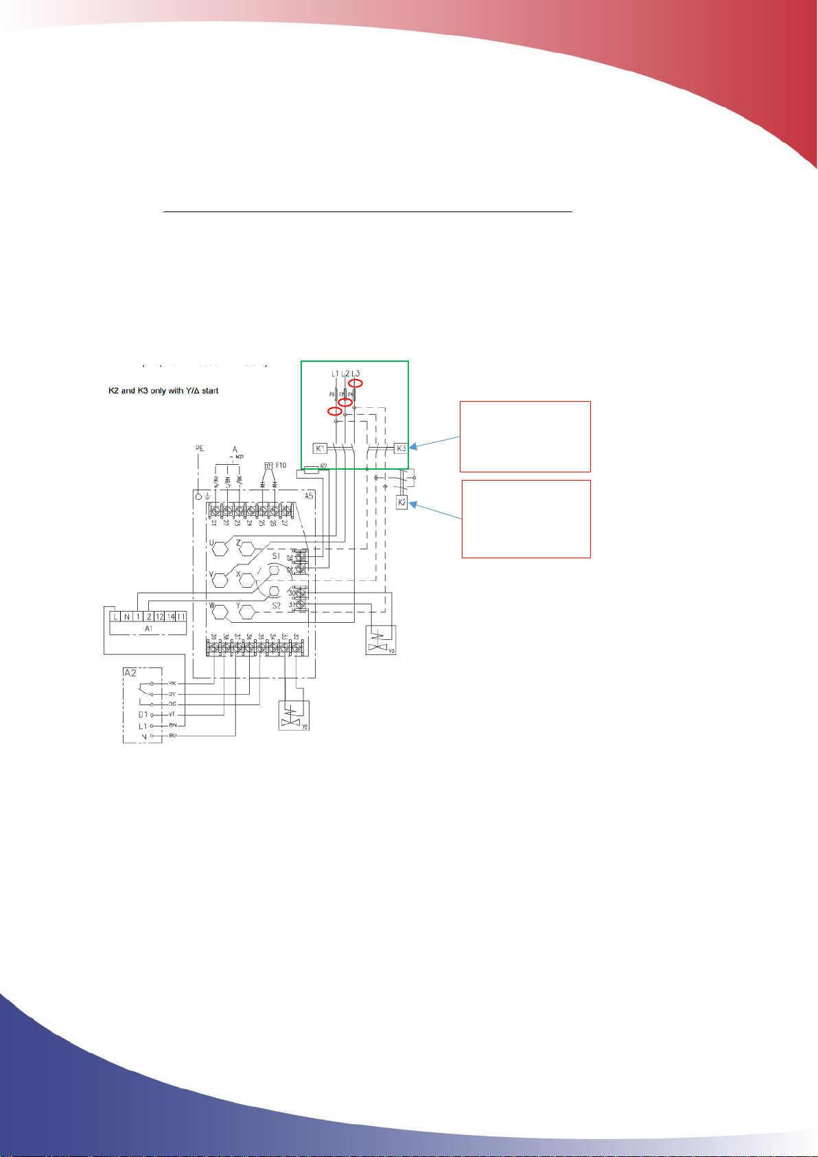
Installation Manual PA Pro III online – 2018-03-16 Page 9 of 30
If measured after the split to K1 and K2/K3 both leads should be measured.
After the “Run” contactor K3 and the split to “Start” contactor K2 the cables to the motor will be
connected to different phases depending on position of K2 and K3.
If measured at motor correct cables must be matched so total L1, L2 respectively L3 feed is
measured but the reading will be incorrect during start when K2 is activated.
In picture below:
L1 is feeding U and Z
L2 is feeding V and X
L3 is feeding W and Y
If designation of poles is unknown the pairs can be identified by measuring voltage between poles
matching pairs will show zero voltage difference.
Figure 1 - Y/D (Star/Delta)
4.2 Systems with inverter
If inverters are used it is normally necessary to measure before inverter and use a loss factor of
typically 3-6% to compensate for the heat loss. Ensure that i.e. fans do not consume power from
the same feed. If so an offset can be added in the input tab
4.3 Differential protection
Differential protection is used to improve the security of the installation and will cut the supply if
any current is drawn outside the “protected loop”. As the EM210 is powered by the voltage line L1
and L2, differential protection must be taken into account when connecting.
Start contactor
Run contactor
 Loading...