

Page 1
Color profile: Disabled
Composite Default screen
The Science of Security™
Prime
Level
FOUR
SECURITY
UPGRADE
PACKAGE
E
N
G
E
R
H
T
R
U
O
F
M
O
B
I
A
T
I
O
N
Installation Manual
Y
T
I
R
L
U
E
C
S
E
D:...-922 Level 4 install manual.vp
Wed Aug 04 17:37:06 1999
1
Page 2

Color profile: Disabled
Composite Default screen
D:...-922 Level 4 install manual.vp
Wed Aug 04 17:37:06 1999
2
Page 3
Color profile: Disabled
Composite Default screen
Table of Contents
Wiring Diagram ...................................2
Important Information ................................3
Required Installation Tools .............................3
Modes: Dealer Mode, Sleep Mode, Customer Mode ................3
Control Unit and Receiver ..............................3
Ignition & Starter...................................3
LED & Valet Switch Assembly ............................3
Door Trigger/Interior Light Supply..........................4
Door Locks .....................................4-5
Single-Stage ........................................4
2-Stage...........................................5
Parking Lights ....................................5
Horn Connection ...................................5
Optional Dual-Zone Piezo Vibration/Impact Sensor ................5
Optional Trunk Trigger Connection .........................6
Auxiliary A Output ..................................6
Auxiliary B Output & Selectable AutoActivation...................6
European Vehicle Window/Sunroof All-Close ........................6
Remote Timed Headlight Activation .............................6
Optional Engine Compartment Connections.....................7
Optional Siren .......................................7
Final Wiring Connections ..............................7
MANDATORY MASTER REMOTE CONTROL ADDITION ................7
Eight-Event TotalRecall ...............................7
Delayed Courtesy Lights ...............................8
Remote Control Operation ..............................8
Programmable Features ...............................8
Using CliffNet Wizard PRO .................................8
Programming User-Selectable Features ..........................8-9
Installer Programmable Features ..............................10
System Checklist & Troubleshooting ......................11-13
NOTE: The Prime Level 1-5 products are designed for easy, plug-in upgrade.
Thus the Level 1 harness is used in the Level 2 installation, the Level 1 and 2
harnesses are used in the Level 3 installation, and so on.
D:...-922 Level 4 install manual.vp
Wed Aug 04 17:37:07 1999
1
3
Page 4
Color profile: Disabled
Composite Default screen
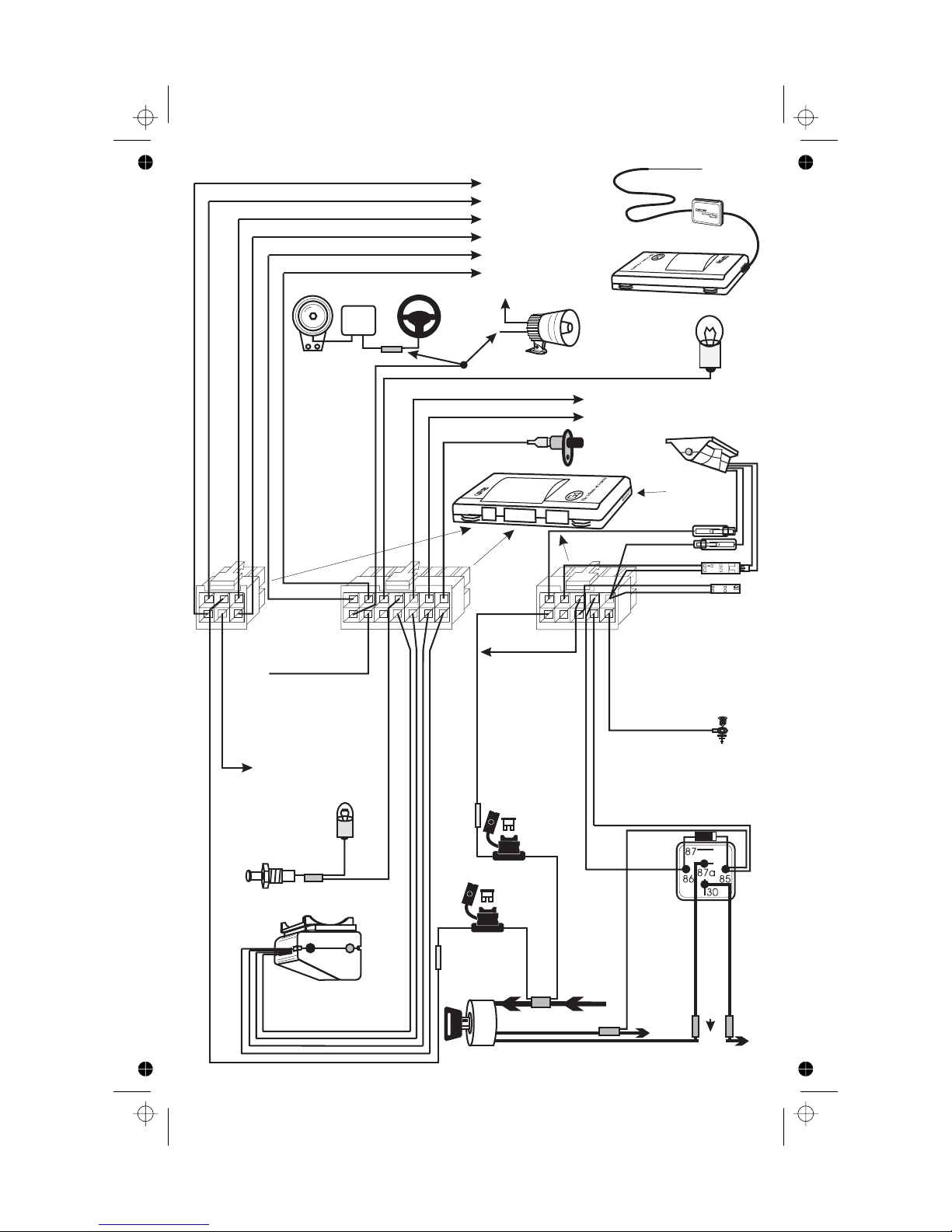
Red/Green (door lock n.o.)
Gray/Green (door lock n.c.)
Red/Orange (door unlock n.o.)
Gray/Orange (door unlock n.c.)
White/Green (door lock comm.)
White/Orange (door unlock comm.)
Siren/Car Horn
Car Horn
64
Output
Factory
Car Horn
Relay
Yellow (horn/siren -)
14 13 9 8
See Door
Lock/Unlock
Section of
This Manual
Optional
+12V
Siren
OR
Red
Black
Brown (parking light output + or -)
Gray/Violet (ch. A out -)
Gray/Blue (ch. B out -)
Gray/Yellow
(trunk input -)
10 6
Prime Level 4 Control Unit
Accessories
Trunk
Switch
Violet (LED +)
Black (ground -)
White (valet switch -)
Black (ground -)
Gray (data input)
Black (ground -)
Parking
Lights
Underdash LED/Valet
Switch Assembly
DataPort
Violet
MX
2E
Not
Used
Black
White
Black
321
Brown/Red
Red/White (parking light input + or -)
Brown/White
(not used)
(interior light supply +or-)
Connect toGround for
NegativeTrigger Pin Switches,
or +12Vfor PositiveTrigger
Pin Switches
Interior
Light
Door
Switch
Optional
Dual Zone
Piezo Sensor
76543 21
Black
Orange
Blue
Red
543 21
Green/White
(armed output 2 -)
(battery +)
Black
(ground -)
Ground
Red
Gray (door trigger + or -)
5 amp
Fuse
20 amp
Fuse
Ignition
Switch
Constant +12V Supply To Switch
(armed output 1 -)
Green
White/Brown
White/Brown
(ignition input +12V)
Ignition
White/Red
White/Red
(starter disable)
Cut
X
(starter disable)
Starter
2
D:...-922 Level 4 install manual.vp
Wed Aug 04 17:37:10 1999
4
Page 5
Color profile: Disabled
Composite Default screen
Important Information
1. Use a voltmeter. DO NOT USE A TEST LIGHT! Test lights have a current drain that
will damage the vehicle’s onboard computer or could trigger the air bag.
2. Keep extension, if needed, as short as possible. Use same-gauge wire for extensions.
3. DO NOT mount components nor route wires near hot or moving vehicle parts.
NOTE: Clifford Electronics’ web site for Authorized Clifford Dealers has
detailed descriptions of wire colors and locations for most foreign and
domestic vehicles. See www.clifforddealers.com for assistance 24-hours per
day or refer to the latest quarterly Tech Support Database CD-ROM.
Required Installation Tools
Voltmeter (set to DC Volt)
n
Wire crimper
n
Wire stripper
n
Electric drill and bits
n
Phillips screwdriver
n
Crescent wrench
n
Vinyl tubing
n
Rubber grommet (if firewall pass-through is needed)
n
Modes: Dealer Mode, Sleep Mode, Customer Mode
There are three modes to provide the utmost flexibility for expediters and new vehicle dealers:
Dealer Mode:
n
system respond only to the master remote in this mode. Beeps are muted, panic and car-finder
features are off, and AutoArm and AutoArm & Lock features are on. Programming the Customer
Care Kit remotes switches the system to Customer Mode and auto-deletes the master remote.
n
Sleep Mode:
the system inoperable in cases where it is not feasible to remove the system control unit. To ensure
against accidental customer access, Sleep Mode is accessible only if the system is in Dealer Mode.
n
Customer Mode:
This is the as-shipped operating mode after you program the master remote. The
This mode completely disables the system. It is intended for unsold pre-loads to make
This is the normal operating mode for the new car purchaser.
Control Unit and Receiver
Never install the control unit under the hood.
1. Select a mounting area, but do not affix the control unit until wiring and testing is complete.
2. Plug in the receiver module. Do not fold or make sharp bends in the cable or antenna wire.
For maximum range, mount the receiver module away from the control unit and run the
antenna up the window pillar and affix it to the windshield about an inch from the roofline.
Ignition & Starter
1. Find the wire in the steering column or ignition switch wireloom that shows +12V throughout
BOTH the cranking AND engine running cycles, and 0 volts when the ignition is off.
2. Connect the WHITE/BROWN wire to the ignition line.
3. Find the wire that shows +12V during the cranking cycle ONLY.
4. Cut it and connect a WHITE/RED wire to each side of the cut wire.
LED & Valet Switch Assembly
1. Select an underdash area to mount the assembly where there is clearance for the screws
and will position the LED so it is visible through the windows.
2. Mate the assembly’s connector to the control unit connector of the same colors.
NOTE: The GRAY & BLACK wire 2-pin connector on the 10-pin connector is not
used on the Level FOUR.
3
5
D:...-922 Level 4 install manual.vp
Wed Aug 04 17:37:11 1999
Page 6
Color profile: Disabled
Composite Default screen
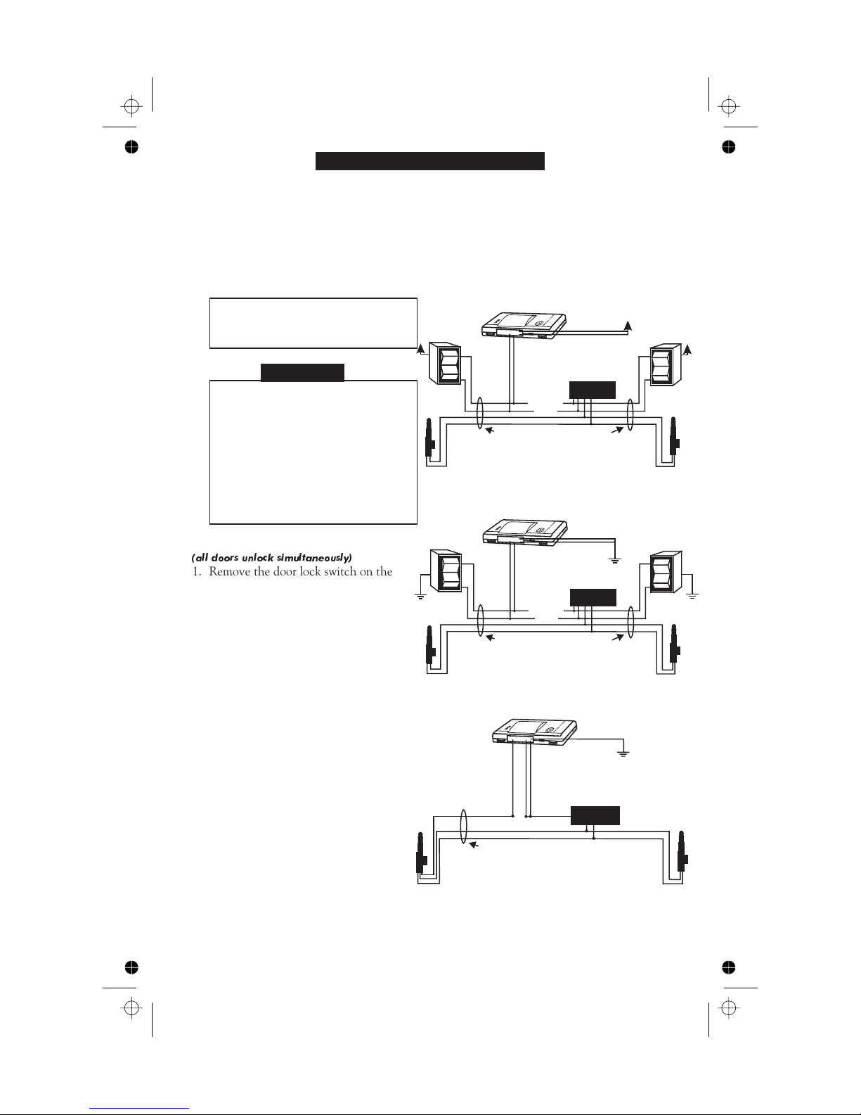
Door Trigger/Interior Light Supply
The Level FOUR has self-programming door trigger polarity. Door triggers on most vehicles
are negative. To verify polarity:
1. Find the one wire off the rear of the door switch that shows +12 volts when the switch is
pressed in and 0 volts when released. This is a negative trigger door wire.
2. If you can’t find such a wire, find the one wire that shows 0 volts when the switch is
pressed in and +12 volts when released. This is a positive trigger door wire.
3. Connect the system’s thin GRAY wire to the door wire.
4. If the door trigger is negative, connect the BROWN/RED wire to ground wire; if positive,
connect it to +12V.
NOTE: The BROWN/WHITE Level
TWO harness wire is not used on
the Level FOUR installation.
Diagram 1: Positive Trigger
+12V
WHITE/ORANGE
WHITE/GREEN
RED/GREEN
RED/ORANGE
+12V
+12V
Door Locks
WARNING: If the power door locks
do not operate properly when the
system is armed and disarmed, DO
NOT USE THE VEHICLE’S DOOR
LOCK SWITCH! Permanent
damage to the control unit or to the
car’s electrical system and lock
servos will result. For assistance,
call the Clifford Technical Support
Hotline at 800-444-4667.
Single-Stage
(all doors unlock simultaneously)
Wires coming in from door at kick panel
The Gray/Orange and Gray/Green wires are not used.
Be sure to insulate these wires separately.
Diagram 2: Negative Trigger
WHITE/ORANGE
WHITE/GREEN
UNLOCK
LOCK
Factory
Lock Module
RED/GREEN
RED/ORANGE
1. Remove the door lock switch on the
driver’s side of the vehicle to reveal the
switch wires.
a. If there are four or more wires, make
the connections shown in Diagram 4.
b. If there are three wires, go to step 2.
c. If the vehicle does not have a door
lock switch, find the wire in the
driver’s kick panel that shows ground
Wires coming in from door at kick panel
The Gray/Orange and Gray/Green wires are not used.
Be sure to insulate these wires separately.
UNLOCK
LOCK
Factory
Lock Module
when unlocked and “open” when
locked. Make the connections shown
in Diagram 3.
Diagram 3: One-Wire Type
2. Find the wire that shows +12V while
activating the switch. Make the
connections shown in Diagram 1.
GRAY/GREEN
WHITE/GREEN
RED/ORANGE
WHITE/ORANGE
Otherwise, go to step 3.
3. Repeat step 2 with the negative
voltmeter lead connected to +12V.
Then find the wire that shows +12V
while activating the switch. Make the
X
Factory
Lock Module
connections shown in Diagram 2.
4. Locks controlled from the driver’s door
key require installation of a #60-516
servo in the driver’s door. Vehicles
Wires coming in from driver’s door at kick panel
The Red/Green and Gray/Orange wires are not used.
Be sure to insulate these wires separately.
without factory power locks require a
servo in each door. Mount the servo(s) and make the connections shown in Diagram 5.
5. On compressor type Mercedes Benz or Audi, make the connections shown in Diagram 6.
6. If needed, after power-up, program the system for 3-second pulsing or double lock and/or
unlock pulses (+ or –).
4
D:...-922 Level 4 install manual.vp
Wed Aug 04 17:37:13 1999
6
Page 7
Color profile: Disabled
Composite Default screen
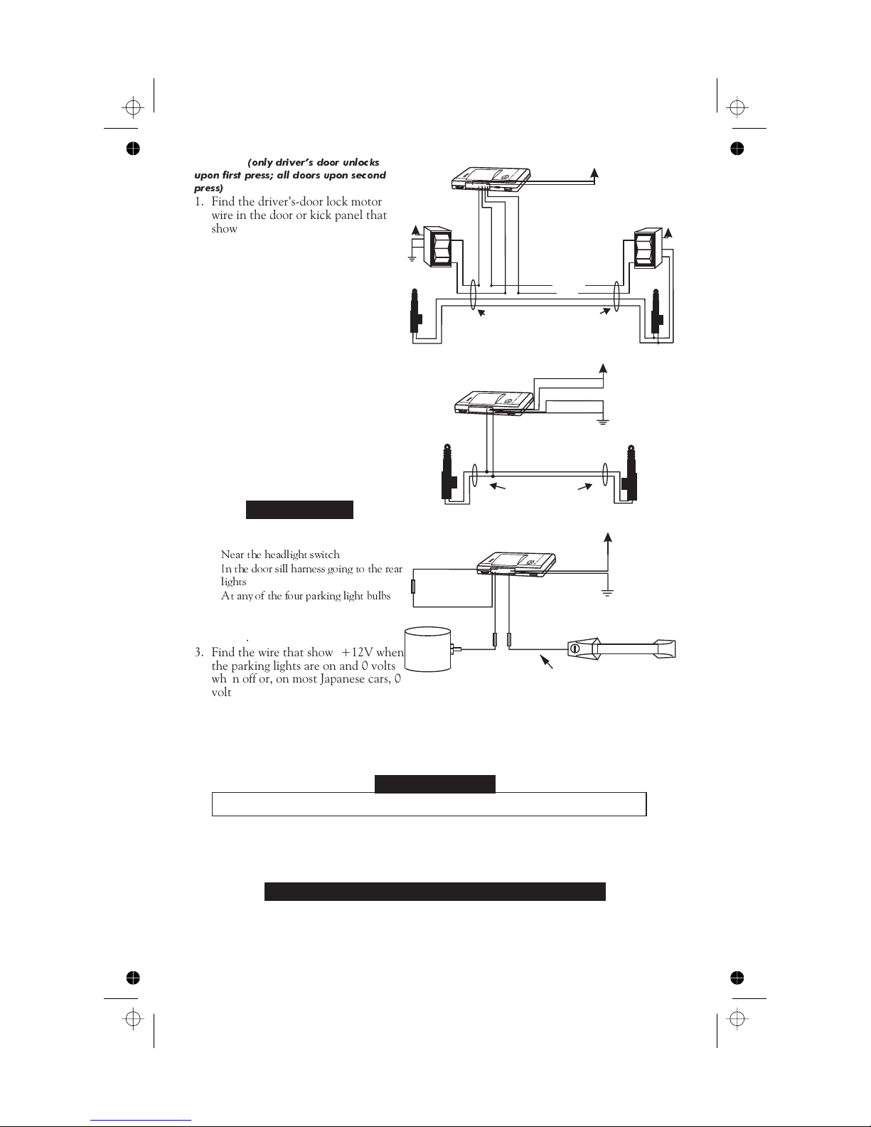
2-Stage
upon first press; all doors upon second
press)
1. Find the driver’s-door lock motor
(only drivers door unlocks
wire in the door or kick panel that
shows +12V when the doors are
+12V
GRAY/ORANGE
WHITE/ORANGE
GRAY/GREEN
RED/GREEN
RED/ORANGE
WHITE/GREEN
Reverse Polarity
unlocked.
2. Cut the wire and activate the switch.
All doors except the driver’s door
should unlock.
3. Connect the WHITE/ORANGE wire
X
X
to the motor side of the cut wire and
the GRAY/ORANGE wire to the
Wires coming in from door at kick panel
switch side.
4. Connect the RED/ORANGE wire to
+12V.
5. Use the negative-pulsing
Diagram 5:
Adding Servos
GRAY/VIOLET Auxiliary A output
to unlock the other doors (add a
relay for lock types that are not
WHITE/ORANGE
WHITE/GREEN
negative-switching).
6. After power-up, set the Auxiliary A
output to 2-Stage Unlock (column 3,
row 3 in installer programming grid).
Wires coming in
from door at kick panel
Parking Lights
1. Turn on the parking lights and access
the parking light wire:
Near the headlight switch
n
n
In the door sill harness going to the rear
lights
n
At any of the four parking light bulbs
2. If working underdash, turn the
Diagram 6: Vacuum Pump
GRAY/GREEN
WHITE/ORANGE
GRAY/ORANGE
WHITE/GREEN
dashlight dimmer to its lowest
setting.
3. Find the wire that shows +12V when
the parking lights are on and 0 volts
when off or, on most Japanese cars, 0
Compressor
cut
X
not drawn to scale
Wire coming in from door at kick panel
volts when on and +12V at rest.
4. Connect the BROWN wire to the parking light wire.
5. Connect the RED/WHITE and preconnected fuseholder to either:
a. +12V if the wire showed +12V in step 3 with the lights on.
b. Ground if the wire showed 0V in step 3 with the lights on.
+12V
Diagram 4:
UNLOCK
LOCK
RED/GREEN
RED/ORANGE
GRAY/ORANGE
GRAY/GREEN
RED/ORANGE
RED/GREEN
+12V
+12V
+12V
Door Switch
NOTE: If connectinga siren, refer to the Optional Sirensection that follows.
1. Locate the wire that shows ground or +12V only when the horn is activated.
a. If ground, connect the YELLOW wire to the negative-switching car horn wire.
b. If +12V, use a relay to invert polarity.
Optional Dual-Zone Piezo Vibration/Impact Sensor
Mount the sensor in the passenger compartment, not in the engine compartment.
1. Firmly mount the sensor near the base of the steering column (if the steering column has a
rotating sleeve, firmly screw the sensor to the interior firewall, kick panel or trunk wall).
2. Mate the sensor to the connector with the ORANGE, BLUE, BLACK and RED wires.
3. After power-up, adjust sensitivity as noted in the instructions that come with the sensor.
D:...-922 Level 4 install manual.vp
Wed Aug 04 17:37:16 1999
Horn Connection
5
7
Page 8

Color profile: Disabled
Composite Default screen
Optional Trunk Trigger Connection
The switch may be located in or near the trunk latch or at the trunk light. Otherwise you
may install a pin switch in a location away from water channels.
1. Connect the GRAY/YELLOW wire to the negative-switching trunk pin switch.
Auxiliary A Output
The Auxiliary A output (GRAY/VIOLET wire) is activated by pressing the ✱ or Opt button
on the remote control. This output is preprogrammed to operate only when the system is
disarmed (e.g., for use as a remote trunk release). It can also be used as the secondary unlock
line if wiring the door locks for 2-stage unlocking (see the previous Door Locks section).
The factory setting is pulsed output (1 second ground). Interlock is on (operates only if the
system is disarmed and the ignition is off). Current is limited to 0.15 amp.
After power-up, see Installer-Programmable Features on page 10 to change the type of output
and/or turn the trunk interlock off or on.
Auxiliary B Output & Selectable AutoActivation
The Auxiliary B output (GRAY/BLUE wire) is activated by pressing the ✱+ button
combination (or Opt+ LOCK button combination) on the remote control. This output can
be programmed as either pulsed, latched or timed, and can also be programmed to operate
only when the system is disarmed (e.g., for use as a remote trunk release).
The factory setting is pulsed output (1 second ground). Interlock is off (operates regardless of
system or ignition state). Current is limited to 0.15 amp.
You can also set this output to automatically activate every time the system is remotely armed
(perfect for vehicles with a window/sunroof all-close feature; see below). After power-up, see
Installer-Programmable Features on page 10 to change the type of output, set AutoActivation
and/or turn the interlock on or off.
European Vehicle Window/Sunroof All-Close
If turning and holding the door key closes the power windows/sunroof (a common feature on
European vehicles), you can make them close upon automatically remote arming:
1. Find the wire that shows +12V or ground when the key is held to lock in the door cylinder.
2. Tap a wire in to this wire and connect to terminal 30 of a relay.
3. If the wire shows ground when the key is turned, connect terminal 87 to ground; if +12V,
connect terminal 87 to 12V.
4. Connect the GRAY/BLUE wire to terminal 85.
5. Connect terminal 86 to +12V.
6. Set the Auxiliary B output to use the timer and to AutoActivate.
7. Set the Accessory Output Timer to 2 seconds longer than the total time it takes to close
all windows/sunroof.
Remote Timed Headlight Activation/Automatic Post-Parking Illumination
You can make the following connections to provide remote timed headlight activation and/or
automatic timed post-parking illumination upon remote arming. Simply follow the steps
above using the wire that shows +12V or ground when the headlight switch is activated. If
you set the output to AutoActivate, the headlights will turn on and stay on for the
programmed duration every time the vehicle is armed.
D:...-922 Level 4 install manual.vp
Wed Aug 04 17:37:16 1999
6
8
Page 9
Color profile: Disabled
Composite Default screen
Optional Engine Compartment Connections
Optional Siren
Mount the siren in the engine compartment away from hot or moving parts and where it
cannot be reached from under the vehicle. Point downward to avoid water collection.
1. Firmly secure the siren to the engine bay firewall or a fender well.
2. Connect the YELLOW wire to the siren’s BLACK ground input.
3. Connect the siren’s RED wire to the system’s 5-amp pre-fused RED wire or directly to the
vehicle battery positive terminal via a separate 5-amp fuse.
4. After power-up, program the horn/siren output for siren (factory setting is for horn).
Final Wiring Connections
1. Attach the fuseholder of the RED wire to a constant +12V supply.
2. Connect the BLACK wire to a grounding bolt (clean to ensure a solid ground).
3. Insert the 5-amp fuse into the RED wire’s fuseholder.
4. Insert the 20-amp fuse into the RED/WHITE wire’s fuseholder.
NOTE: Power and test accessories after the basic system has been tested.
Individually fuse all accessory power and fuse panel connections.
MANDATORY MASTER REMOTE CONTROL ADDITION
After power-up, you MUST program the system to respond to the Master Remote Control
used by that dealership. To do so, get one of the master remotes used at that dealership (all
master remotes at a dealership are the same code) and do the following:
1. Turn the ignition on.
2. Toggle the valet switch (located behind the LED assembly) in the following manner:
a. Left, left, right, then press and hold to the left.
b. After 3 seconds of holding to the left, you’ll hear a horn beep.
c. Right once, then wait 2 seconds for the horn beep.
d. Left once (one beep), then press the LOCK button on the master remote (two beeps).
3. Turn the ignition off (3 beeps).
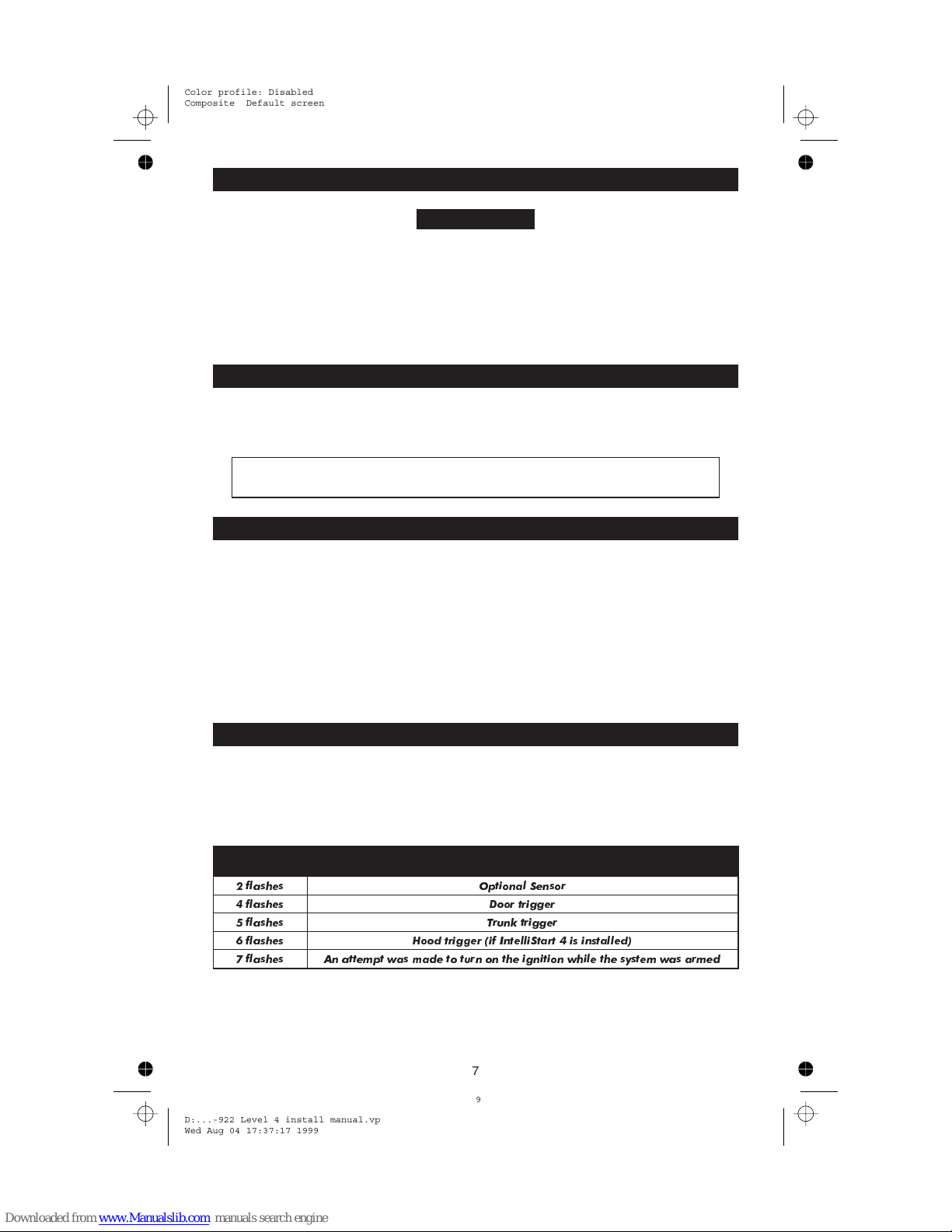
Eight-Event TotalRecall
1. With the ignition OFF, hold the valet switch (at the rear of the LED assembly) to the
right.
2. Use the remote control to lock, then unlock, then release the valet switch.
3. The LED will flash 2–10 times, pause, then flash 2–10 times, etc.
4. Refer to the following chart. The first set of flashes was the most recently activated trigger
or sensor. The next is the second most recent, and so on up to as many as the last eight.
LED flashes Trigger/sensor indication
2 flashes Optional Sensor
4 flashes Door trigger
5 flashes Trunk trigger
6 flashes Hood trigger (if IntelliStart 4 is installed)
7 flashes An attempt was made to turn on the ignition while the system was armed
7
9
D:...-922 Level 4 install manual.vp
Wed Aug 04 17:37:17 1999
Page 10
Color profile: Disabled
Composite Default screen
Delayed Courtesy Lights
Delayed or dimming courtesy lights interfere with remote arming. If the delay is more than 5
seconds, turn on the Delayed Courtesy Lights feature noted on page 10.
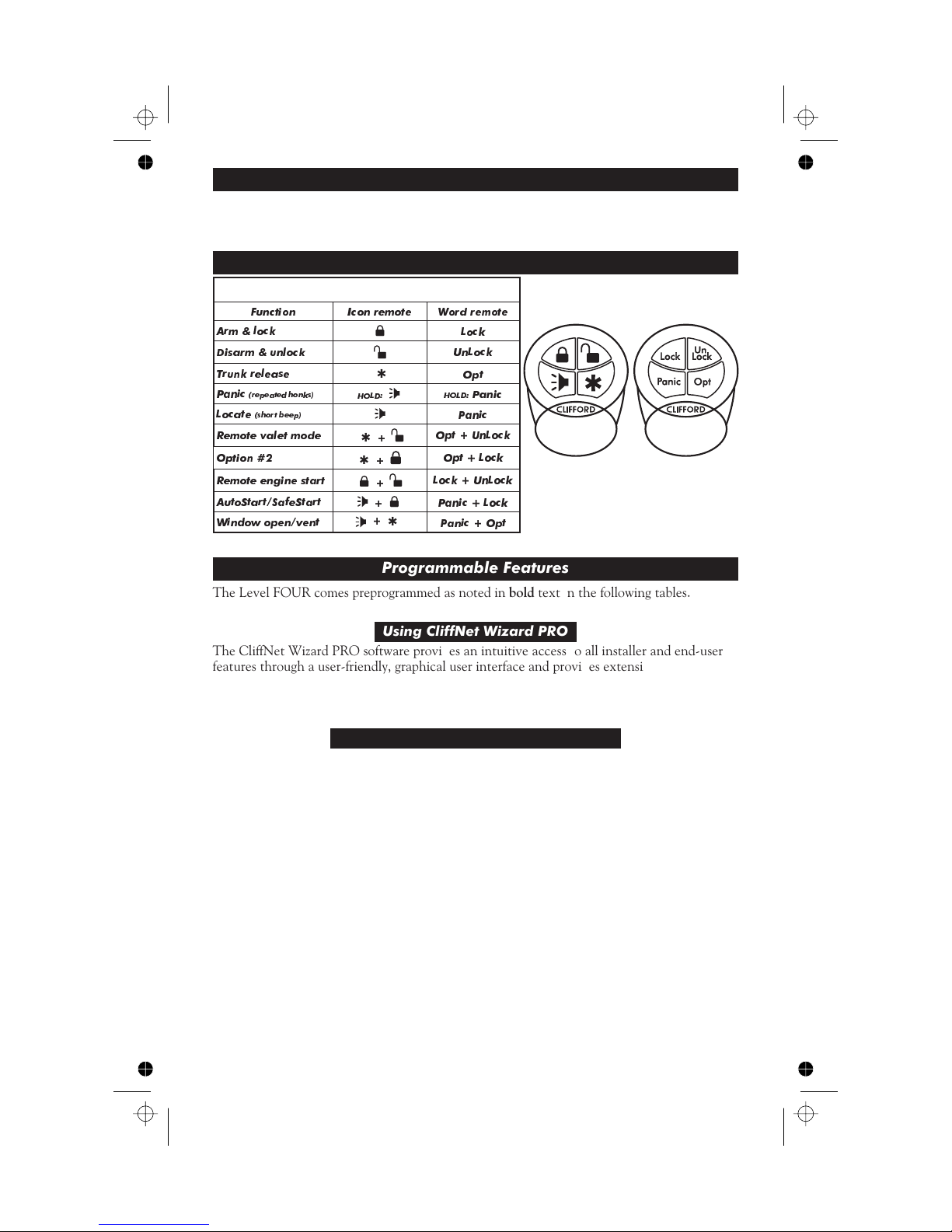
Remote Control Operation
REMOTE FUNCTIONS
Function Icon remote Word remote
Arm & lock
Disarm & unlock
Trunk release
Panic
(repeated honks)
(short beep)
Locate
Remote valet mode
Option #2
Remote engine start
AutoStart/SafeStart
Window open/vent
HOLD:
✱
✱
✱
+
+
+
+
+
✱
Lock
UnLock
Opt
HOLD:
Panic
Panic
Opt + UnLock
Opt + Lock
Lock + UnLock
Panic + Lock
Panic + Opt
Programmable Features
The Level FOUR comes preprogrammed as noted in bold text in the following tables.
Using CliffNet Wizard PRO
The CliffNet Wizard PRO software provides an intuitive access to all installer and end-user
features through a user-friendly, graphical user interface and provides extensive diagnostic
capabilities. See www.clifforddealer.com to download a free copy of the program (a #60-509
cable set is required to connect your Windows PC or palmtop to the G4 DataPort).
Programming User-Selectable Features
1. Note the column (across) and row (down) numbers of the feature(s) you wish to program.
2. Turn the ignition to the “ON” position or start the engine.
3. Enter the factory preset valet/programming code of “2” by toggling the valet switch
(located behind the LED assembly) to the left two times, then to the right (LED on).
4. Immediately hold to the left for about 3 seconds until you hear one horn beep and the
LED turns on to confirm the system is in the “Feature Select” position.
5. Select the feature column: Toggle the switch to the right the number of times indicated
for the column. Pause. You will hear the same number of horn beeps, confirming your
selection.
6. Within five seconds, select the feature row: Toggle the switch to the left the number of
times indicated for the row. You’ll hear a beep each time to help you count.
7. If there is a NOTE for the selected feature, perform the actions noted.
8. Pause. You will hear either one or two beeps: two beeps = ON, one beep = OFF.
9. You can select another feature, or you can exit program mode:
a. To select another feature in that same column, repeat step 6 within the next five
seconds (after five seconds, three beeps indicate return to the “Feature Select” position).
b. To select a different feature column, repeat step 5.
c. To exit program mode, turn the ignition off (you’ll hear three beeps and the LED will
turn off), or wait 60 seconds for the system to automatically exit program mode.
D:...-922 Level 4 install manual.vp
Wed Aug 04 17:37:19 1999
8
10
Page 11
Color profile: Disabled
Composite Default screen
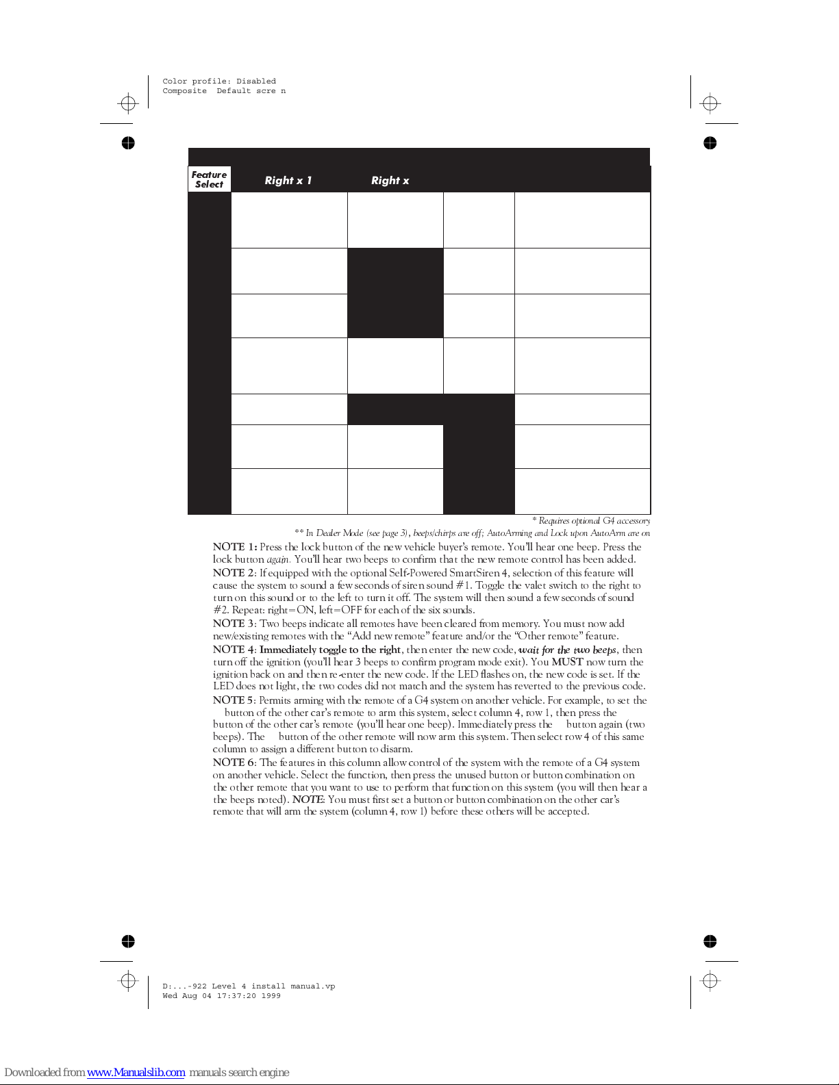
User-Selectable Features (Customer Mode): 1 beep = OFF, 2 beeps= ON
Feature
Select
Left x
1
Left x
2
Left x
3
Left x
4
Left x
5
Left x
6
Left x
7
n
NOTE 1:
lock button
n
NOTE 2
cause the system to sound a few seconds of siren sound #1. Toggle the valet switch to the right to
turn on this sound or to the left to turn it off. The system will then sound a few secondsof sound
#2. Repeat: right=ON, left=OFF for each of the six sounds.
n
NOTE 3
new/existing remotes with the Add new remote feature and/or the Other remote feature.
n
NOTE 4:Immediately toggle to the right
turn off the ignition (youll hear 3 beeps to confirm program mode exit). You
ignition back on and then re-enter the new code. If the LED flashes on, the new code is set. If the
LED does not light, the two codes did not match and the system has reverted to the previous code.
n
NOTE 5
✱
button of the other cars remote (youll hear one beep). Immediately press the✱button again (two
beeps). The
column to assign a different button to disarm.
n
NOTE 6
on another vehicle. Select the function, then press the unused button or button combination on
the other remote that you want to use to perform that function on this system (you will then hear a
the beeps noted).
remote that will arm the system (column 4, row 1) before these others will be accepted.
Right x 1 Right x 2 Right x 3 Right x 4
Chirps*/beeps:
Add a new remote
NOTE 1
off**/on/quiet
(1/2/3
AutoArming:
off/on**
NOTE 5 — Other remote:
arm (1 then 2 beeps)
chirps*/beeps)
Personalized Siren
Sounds*
NOTE 2
Play Siren Sounds*:
trigger only/always
(1/2 beeps)
Siren duration:
30/60/90sec.
(1/2/3 beeps)
AutoLock: off/on/rpm*
(1/2/3 beeps)
AutoUnLock: off/on
Reset all features to
default (except
remotes & valet code)
** In Dealer Mode (see page 3), beeps/chirps are off; AutoArming and Lock upon AutoArm are on
NOT USED
NOT USED
AutoStart*: both
off/both on/temp
only/battery only
(1/2/3/4 beeps)
NOT USED NOT USED
Clear all remotes
NOTE 3
Set a new secret
valet code
NOTE 4
Lock upon
AutoArming:
off/on**
AutoArming
entry delay:
off/on
FACT: off/on
NOT USED
NOT USED
NOTE 6 — Other remote:
trunk release (2 beeps)
NOTE 6 — Other remote:
panic (3 beeps)
NOTE 6 — Other remote:
disarm (4 beeps)
NOTE 6 — Other remote:
remote starting* (5 beeps)
NOTE 6 — Other remote:
window rolldown/venting*
(6 beeps)
NOTE 6 — Other remote:
valet mode (7 beeps)
* Requires optional G4 accessory
Press the lock button of the new vehicle buyers remote. Youll hear one beep. Press the
again.
Youll hear two beeps to confirm that the new remote control has been added.
: If equipped with the optional Self-Powered SmartSiren 4, selection of this feature will
: Two beeps indicate all remotes have been cleared from memory. You must now add
, then enter the new code,
wait for the two beeps
MUST
: Permits arming with the remote of a G4 system on another vehicle. For example, to set the
button of the other cars remote to arm this system, select column 4, row 1, then press the
✱
button of the other remote will now arm this system. Then select row 4 of this same
: The features in this column allow control of the system with the remote of a G4 system
NOTE
: You must first set a button or button combination on the other cars
, then
now turn the
✱
D:...-922 Level 4 install manual.vp
Wed Aug 04 17:37:20 1999
9
11
Page 12
Color profile: Disabled
Composite Default screen
Installer-Programmable Features
1. Turn on the ignition.
2. Enter the factory preset valet/programming code of “2” by toggling the valet switch
(located behind the LED assembly) to the left two times, then to the right.
3. Hold the switch to the left. You’ll hear one beep after about 3 seconds to indicate user
programming mode. KEEP HOLDING (about 12 more seconds) until you hear the
3-beep installer programming mode confirmation.
4. Select the feature column: Toggle the switch to the right the number of times indicated
for the column. Pause. You will hear the same number of horn beeps, confirming your
selection.
5. Within five seconds, select the feature row: Toggle the switch to the left the number of
times indicated for the row. You’ll hear a beep each time to help you count.
6. If there is a NOTE for the selected feature, perform the actions noted.
7. Pause. You will hear either one or two beeps: two beeps = ON, one beep = OFF.
8. You can select another feature, or you can exit program mode:
a. To select another feature in that same column, repeat step 5 within the next five
seconds (after five seconds, three beeps indicate return to the “Feature Select” position).
b. To select a different feature column, repeat step 4.
c. To exit program mode, turn the ignition off (you’ll hear three beeps and the LED will
turn off), or wait 60 seconds for the system to automatically exit program mode.
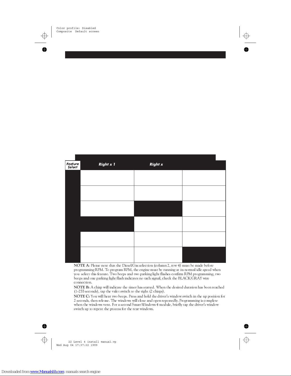
Installer-Programmable Features: 1 beep = OFF, 2 beeps = ON
Feature
Select
Left x
1
Left x
Left x
Left x
Left x
Left x
Single/Double Unlock Pulse
2
3
4
IntelliStart 4: Program RPM
5
6
n
NOTE A
programming RPM. To program RPM, the engine must be running at its normal idle speed when
you select this feature. Two beeps and two parking light flashes confirm RPM programming, two
beeps and one parking light flash indicates no tach signal, check the BLACK/GRAY wire
connection.
n
NOTE B:
(1-255 seconds), tap the valet switch to the right (2 chirps).
n
NOTE C:
2 seconds, then release. The windows will close and open repeatedly. Programming is complete
when the windows vent. For a second SmartWindows 4 module, briefly tap the drivers window
switch up to repeat the process for the rear windows.
Right x 1 Right x 2 Right x 3
Single/Double
Lock Pulse
(1 beep/2 beeps)
(1 beep/2 beeps)
Lock/Unlock Pulse:
1 second/3 second
(1 beep/2 beeps)
NOT USED
NOTE A
Car Horn/Optional Siren
(1 beep/2 beeps)
: Please note that the Diesel/Gas selection (column 2, row 4) must be made before
A chirp will indicate the timer has started. When the desired duration has been reached
You will hear two beeps. Press and hold the drivers window switch in the up position for
Accessory Output Timer
Duration (10sec.): 1-255
sec. NOTE B
Accessory Output B type:
(Pulsed/Timed/Latched)
(1 beep/2 beeps/3 beeps)
NOT USED
IntelliStart 4: Diesel/Gas
(1 beep/2 beeps)
Program Optional
SmartWindows 4 NOTE C
Sleep Mode (only if in
dealer mode, see page 3)
(On/Off)
Door Ajar Warning
/Delayed Courtesy Lights
(1 beep/2 beeps)
Accessory Output A
Trunk Interlock
(On/Off)
Accessory Output A for
2-Stage Unlocking
(pgs 5 & 10) (On/Off)
Accessory Output B
Trunk Interlock
(On/Off)
AutoActivate Accessory
Output B Upon Remote
Arming (On/Off)
NOT USED
D:...-922 Level 4 install manual.vp
Wed Aug 04 17:37:22 1999
10
12
Page 13
Color profile: Disabled
Composite Default screen
System Checklist & Troubleshooting
The following checklist will assure that you have installed the Level FOUR correctly. Each
successive step requires that the previous step has been completed as indicated.
NOTE: If you are still having trouble after performing the following steps,
please call Clifford Technical Support Services at 1-800-444-4667.
Step 1: Test the immobilization circuit.
Arm the system by pressing the LOCK button on the Dealer Master remote (note: there are
no arm/disarm beep confirmations in Dealer Mode [see page 3]) from inside the vehicle and
wait 10 seconds. Turn the ignition to the “START” position.
Engine does not respond.
n
4 beeps:
n
n
n
n
n
NOTE: If the 20-amp fuse blows upon arming:
n
n
n
If 4 beeps immediately or 5-10 seconds after arming, a trigger or sensor is open or active,
or the vehicle has delayed courtesy lights and the Delayed Courtesy Lights feature has not been
programmed on. Disarm and use the Eight-Event TotalRecall feature noted on page 7 to identify
the open/active input. If the
Engine starts or cranks.
noted in the
Make sure the fuses are in the fuseholders and check the power and ground connections.
Verify the control unit connectors are properly inserted into the control unit.
Verify the ignition wire is connected to the true ignition line instead of a +12V line.
Disconnect the systems parking light wire, replace the 20-amp fuse and rearm. If the fuse does not
blow, the parking light wire is shorting.
If the fuse blows while the parking light wire is disconnected, the door locks are not wired correctly.
Reconnect the vehicles power locking system to its original condition, then retest the voltages as
indicated in the
If engine still starts or cranks after retesting all the wiring, check the power and ground
connections. Make sure fuses are in the fuseholders, verifythe control unit connectors are securely
fastened, verify the ignition input wire is connected to the true ignitionline insteadof a +12V or
accessory line, and verify the transmitters are programmed.
Starter Connection
Door Locks
This is the correct response, proceed to step 2.
door trigger
The starter or ignition connection is miswired. Retest the vehicle wires as
section.
is indicated, activate the delayed courtesy lights feature.
section on page 3.
Step 2: Test the horn connection.
Rapidly turn the ignition on then off (this invokes the AutoArming Bypass feature):
n
1 beep:
This is the correct response. Proceed to step 3.
n
No beeps:
Check horn connections.
Step 3: Test the parking lights.
Arm the system with the remote control.
n
Two flashes.
n
No flashes.
RED/WHITE wire is connected to a constant +12V source and that the 20-amp fuse is not blown.
If so, see the
n
Only one side flashes.
circuits; call Technical Support at 1-800-444-4667.
This is the correct response, proceed to step 4.
If no flashes, verify the parking light bulbs are operational. Verify that the
Parking Lights
section.
If only the left or the right side parking lights flash, the vehicle has dual
Step 4: Test the door locks.
Arm the system by pressing the Lock button on the remote control.
n
Doors lock.
n
Doors do not lock.
polarity or connected the wires incorrectly. Reconnect the vehicles locking system to its original
condition, then retest as indicated in the
WARNING: If the doors do not lock, DO NOT activate the vehicle’s lock
switches. Doing so may damage the control unit, the vehicle’s electrical
system and/or the power lock servo motors.
D:...-922 Level 4 install manual.vp
Wed Aug 04 17:37:23 1999
This is the correct response, proceed to step 5.
You either selected the wrong lock diagram, programmed the wrong lock
Door Locks
section.
11
13
Page 14
Color profile: Disabled
Composite Default screen
Doors unlock.
n
Reconnect the vehicles power locking system to its original condition, then retest the voltages as
indicated in the
Only one door locks.
n
incorrectly. Reconnect the vehicles power locking system to its original condition, then retest the
voltages as indicated in the
You either selected the wrong door lock diagram or connected the wires incorrectly.
Door Locks
section and wire the locks as indicated.
You either selected the wrong door lock diagram or connected the wires
Door Locks
section.
Step 5: Test the valet switch.
Test switch operation by entering programming mode as noted on page 8. If no response:
Verify the WHITE/BROWN wire has +12V when the ignition is ON and 0V when OFF. If not
n
refer to
Ignition Connection
Verify the WHITE wire rests at +5V, shows +3V when toggled to the left and 0V when held to
n
the right. If not, test the switchs BLACK wire. It should read 0V at rest, 0V when pressed to the
left and 0V when pressed to the right. If the BLACK wire tests incorrectly, check the ground
circuit. If both wires test correctly, the valet code has been changed. Use CliffNet Wizard PRO to
reset the PIN code.
on page 3.
Step 6: Test the LED.
Arm the system with the remote control.
Flashes repeatedly.
n
No flashes.
n
This is a 2-volt LED, testing with 12 volts will destroy the LED.
This is the correct response, proceed to step 7.
Verify that the LEDs VIOLET and BLACK wires are properly connected.
Warning:
Step 7: Test the disarm function.
Disarm by pressing remote control button 1. The following should occur (note: there are no
arm/disarm beep confirmations in Dealer Mode [see page 3]):
Parking lights flash once.
n
LED stops flashing.
n
n
Doors unlock.
n
Immobilizer circuit immediately disengages
immobilizer circuit does not disengage, refer to step 1.
n
Interior courtesy light(s) turn on
§
If the interior light(s) do not turn on, verify that you replaced the interior light fuse if removed or
have turned the lights back on.
§
If the fuse blew when you disarmed, the vehicle uses a positive door trigger and you connected
the interior light supply wire to ground instead of +12V.
§
Check the door trigger circuit.
If not refer to step 4.
If the parking lights do not flash once, refer to step 3.
(test by starting the engine with the key). If the
and stay on for 30 seconds or until ignition on.
Step 8: Test the door trigger circuit.
Rearm, then use the key to unlock and open the driver’s door.
n
Horn sounds, parking lights flash repeatedly.
n
Horn does not sound immediately.
1.5 volts if negative-switching or more than +11 volts if positive-switching.
Make sure the door pin switches consistently show less than
This is the correct response, proceed to step 9.
Step 9: Test the optional trunk trigger circuit.
Arm the system, then use the key to unlock the trunk.
n
Horn sounds immediately, parking lights flash repeatedly.
to step 10.
n
Alarm does not sound immediately.
trunk pin switch is working properly and, when open, is consistently showing less than 1.5 volts.
Also make sure the trunk pin switch is connected to the correct wire. If not, the trunk pin switch
must be thoroughly cleaned or replaced.
D:...-922 Level 4 install manual.vp
Wed Aug 04 17:37:24 1999
If the alarm does not sound immediately, make sure that the
12
14
This is the correct response, proceed
Page 15
Color profile: Disabled
Composite Default screen
Step 10: Test the optional Dual-Zone Piezo Sensor.
Arm, wait 10 seconds, then tap the car softly with your fist. The following should occur:
Horn beeps five times.
n
This is the correct response.
Hit the car firmly with your fist. The following should occur:
Alarm triggers.
n
Proceed to step 11.
If either of these test fail, adjust the sensor using the adjustment knob and retest. Keep in
mind that the sensor does not come online until about 10 seconds after arming.
Step 11: Test range and optional accessories.
Testing range and optional accessories, such as trunk release or the IntelliStart 4 remote
engine starting accessory, will require temporary addition of a Customer Care Kit remote
control. When testing is complete, reprogram the master remote control into the system. This
clears out the codes of any Customer Care Kit remote controls and returns the system to
Dealer Mode.
To test range, stand 30 feet from the vehicle and use the remote control to arm and disarm.
The system will respond as previously noted. If not:
n
Reposition the external receiver as high as possible under the dash and as far as possible from
§
heavy wirelooms and metal.
Reposition the antenna rod underdash or, for maximum range, run the antenna cable up the
§
window pillar and mount the antenna rod on the windshield about an inch below the roofline.
Make sure that the remote control battery measures at least 3 volts
§
Make sure the voltage at the control unit between the 5-amp fused power line and each the
§
ground line is at least 12.0 volts when triggered (if less, make sure the ground connection is solid;
if so, the vehicle battery may need charging, servicing or replacement).
Make sure no accessories are tapped in to the RED or BLACK power and ground wires.
§
while
transmitting.
D:...-922 Level 4 install manual.vp
Wed Aug 04 17:37:24 1999
13
15
Page 16

/
Color profile: Disabled
Composite Default screen
USA Headquarters West
20750 Lassen Street Chatsworth, California 91311
1-800-CLIFFORD or 1-800-824-3208 or 1-818-709-7551
USA Headquarters East
1535 Barclay Boulevard Buffalo Grove, Illinois 60089
1-800-CLIFFORD or 1-800-824-3208 or 1-818-709-7551
Canada Headquarters
4513 Dobrin Street Montreal, Quebec H4R 2L8
1-800-361-3444 or 1-514-332-4444
UK Headquarters
Boundary Business Court
92/94 Church Road Mitcham, Surrey CR4 3TD
0800 929949 or 0181 646 8440
Germany Headquarters
Schlesische Straße 27 10997 Berlin
0130 115 681 oder 030 611 2602
Mexico Headquarters
Saratoga 804 B, Col. Portales
Deleg. Benito Juárez 03300 México D.F.
01 800 021 2543 o 5 605 0382
Netherlands Headquarters
Trompenburgstraat 8A
1079 TX Amsterdam
020 40 40 919
Clifford systems are covered by one or more of these
Clifford Electronics USA patents: 4,158,874; 4,233,642;
4,327,444; 4,383,242; 4,430,685; 4,845,464; 4,887,064;
4,890,108; 4,922,224; 4,997,053; 5,081,667; 5,146,215;
5,157,375; 5,467,070; 5,650,744 and other patents pending
AutoFax & Technical Support Helpline:
1-800-444-4667
For the latest vehicle wiring information and for
wiring diagrams and servicing information on older
Clifford products:
24-hour AutoFax:
1-800-444-4667
24-hour dealer website: www.clifforddealer.com
Quarterly Authorized Dealer Technical Support CD-ROM
© Clifford Electronics, Inc., 1999
D:...-922 Level 4 install manual.vp
Wed Aug 04 17:37:25 1999
32-922
PrimeL4im/0799
16
 Loading...