

Page 1
1 | 111
P/N :
Cover Page
Cover page
PT6100
User Manual
Version: 1.0
Page 2

Clientron PT6100 User Manual
Version: 1.0
2 | 111
Copyright
Copyright 2014 Publishing. All Rights Reserved.
This manual, software and firmware described in it are copyrighted by their respective owners
and protected under the laws of the Universal Copyright Convention. You may not reproduce,
transmit, transcribe, store in a retrieval system, or translate into any language, in any form or
by any means, electronic, mechanical, magnetic, optical, chemical, biological, molecular,
manual, or otherwise, any part of this publication without the express written permission of the
publisher.
All products and trade names described within are mentioned for identification purpose only.
No affiliation with or endorsement of the manufacturer is made or implied. Product names and
brands appearing in this manual are registered trademarks of their respective companies.
The information published herein has been checked for accuracy as of publishing time. No
representation or warranties regarding the fitness of this document for any use are made or
implied by the publisher. We reserve the right to revise this document or make changes in the
specifications of the product described therein at any time without notice and without obligation
to notify any person of such revision or change.
Page 3

Clientron PT6100 User Manual
Version: 1.0
3 | 111
Safety Instructions
1. Read these instructions carefully. Keep these instructions for future reference.
2. Please disconnect this equipment from AC outlet before cleaning. Don’t use liquid or
sprayed detergent for cleaning. Use moisture sheet or cloth for cleaning.
3. Please keep this equipment from humidity.
4. Lay this equipment on a reliable surface when install. A drop or fall could cause injury.
5. Make sure power cord such a way that people can not step on it. Do not place anything
over the power cord.
6. All cautions and warnings on the equipment should be noted.
7. If the equipment is not used for long time, disconnect the equipment from main to avoid
being damaged by transient over voltage.
8. Never pour any liquid into opening, this could cause fire or electrical shock.
9. If one of the following situations arises, get the equipment checked by a service
personnel:
a. The power cord or plug is damaged.
b. Liquid has penetrated into the equipment.
c. The equipment has been exposed to moisture.
d. The equipment does not work well or you can not get it work according to user
manual.
e. The equipment has dropped and damaged.
10. Do not leave this equipment in an environment unconditioned, storage temperature below
-20°C or above 60°C, it may damage the equipment.
11. Unplug the power cord when doing any service or adding optional kits.
Lithium Battery Caution:
1. Danger of explosion can happen if the battery is incorrectly replaced. Replace only the
original or equivalent type recommended by the manufacture. Dispose used batteries
according to the manufacture’s instructions.
Do not remove the cover, and ensure no user serviceable components are inside. Take the
unit to the service center for service and repair.
Page 4

Clientron PT6100 User Manual
Version: 1.0
4 | 111
Table of Contents
1. Packing List………………………………………………
1-1 Standard Accessories………………………………………..
1-2 Optional Accessories………………………………………...
2. System View ……………………………...………. ……
2-1 Rear View……………………………………………………..
2-2 Specification…………………………………………………..
2-3 Internal Layout………………………………………………..
3. Pin Definition……………………………………………...
4. Rear I/O Interface…………………..……………………
5. System Assembly & Disassembly……………………
5-1 HDD…………………………………………………………....
5-2 CFast ard…………………………………………………….
5-3 MSR…………………………………………………………...
5-4 UPS Battery………………………………………………......
5-5 Cable Cover………………………………………………......
5-6 15” 2nd Display………………………………………………..
5-7 Internal VFD…………………………………………………..
5-8 Wi-Fi…………………………………………………………..
5-9 8” 2nd Display…………………………………………………
5-10 1D/2D/i-Button with RFID module…………………..……...
5-11 Pole type VFD VD1220……………...…………..…………..
6. Device Driver Installation………………………………
6-1 Resistive Type Touch Panel & P-CAP………....…………..
6-2 MagStripe Card Reader Configuration Utility…………...
6-3 Fingerprint Reader………………………………………….
6-4 RFID...………………………………………………………...
6-5 Internal VFD………………………………………………….
6-6 Configuration Utility of i-Button Reader………………..…..
6-7 Installation and Testing of Smart Card Reader……………
6-8 Wi-Fi…………………………………………………………..
6-9 Pole type VFD VD1220 ……………………………………
P6
P6
P6
P7
P7
P8
P9
P10
P12
P14
P14
P14
P16
P16
P17
P17
P21
P22
P24
P27
P28
P30
P30
P36
P51
P61
P71
P75
P86
P91
P94
Page 5

Clientron PT6100 User Manual
Version: 1.0
5 | 111
7. BIOS/Utility Setup………………………………………..
8. LCD Surface Cleaning…………………………………..
P99
P110
Page 6
Clientron PT6100 User Manual
Version: 1.0
6 | 111
Packing List
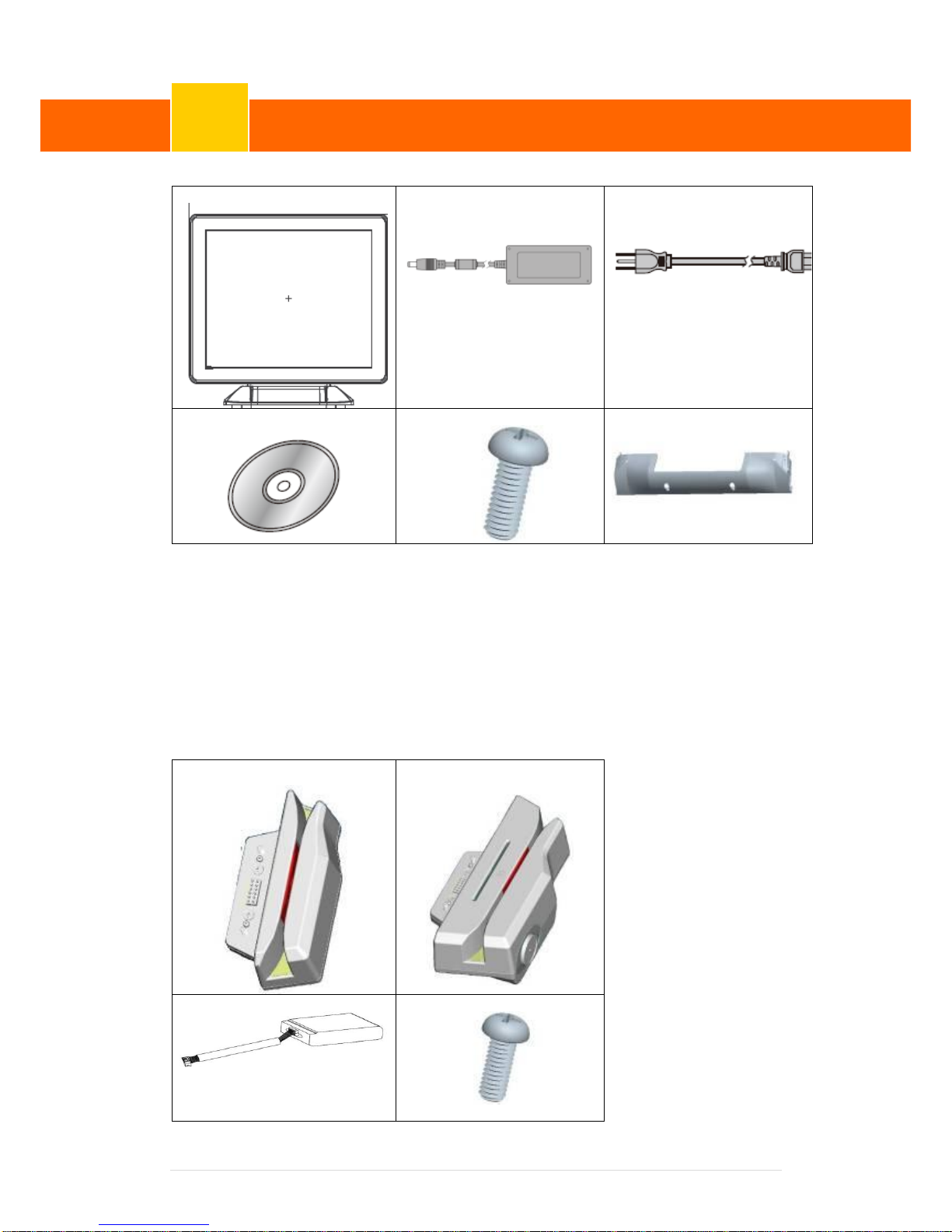
1-1 Standard Accessories
a. b.
c.
d. e. f.
a. System (with stand)
b. Power Adapter
c. Power Cord
d. Driver Bank
e. Screw x2
f. Cable Cover
1-2 Optional Accessories
a.
b.
a. Single MSR
b. 3 IN 1 MSR
c. UPS Battery
d. Screw x2
c. d.
Packing List
1
Page 7
Clientron PT6100 User Manual
Version: 1.0
7 | 111
2
System View
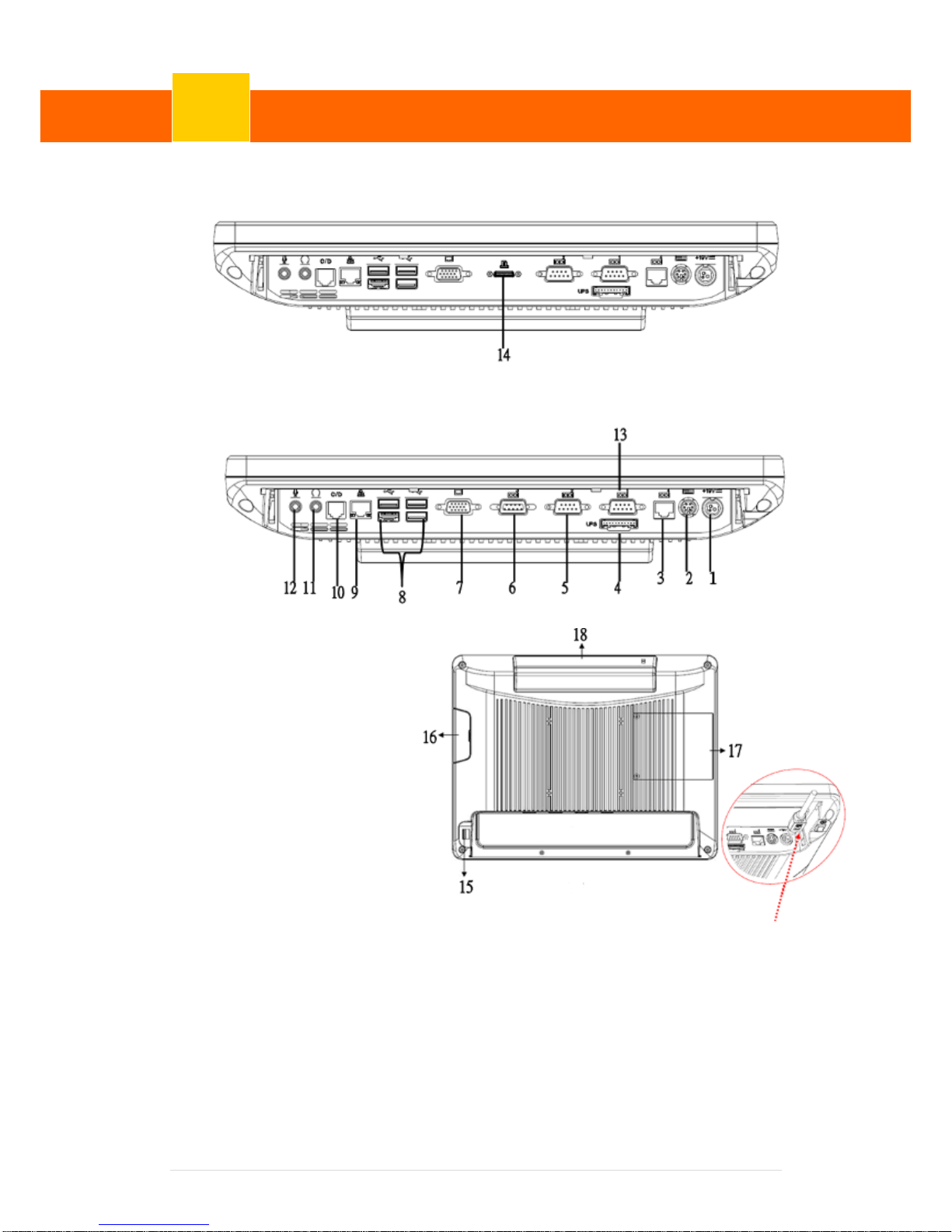
2-1 Rear View with Optional LPT Port
Rear View Standard
Item
1. 19V DC Input
2. PS2(K/B)
3. RJ45(COM 4 for External
VFD)
4. UPS Battery(Option)
5. COM2
6. COM3
7. VGA
8. USB 2.0/1.1 X4
9. RJ45(LAN)
10. RJ11(Cash Drawer)
11. Line-Out
12. Mic
13. COM1
14. Parallel port
(Option :Alterative to
COM 3)
15. Power Button
16. MSR/Smart Card
/i-Button /Fingerprint
/RFID (Option)
17. HDD/CFast CARD
18. VFD(Option)
☆ Please make sure 19V DC plug in the right direction before
plugging in DC jack.
System View
2
Page 8

Clientron PT6100 User Manual
Version: 1.0
8 | 111
2-2 Specification
Processor
Intel® Celeron J1900 Quad Core 2.0Ghz
Memory
One SO-DIMM socket supports DDR3L up to 8GB
Audio
Line-out/Mic-in
Network
RJ45 10/100/1000 Base-T
USB
4*USB 2.0
Storage
CFast card / 2.5” SATAII HDD / SSD
BIOS
Insyde BIOS
Power
AC 19V 90W Adaptor
Thermal Solution
Fan-less
Dimension
368 (W) x 264.2 (H) x 285 (D) mm
Operating Temperature
0°C ~ 35°C
Storage Temperature
-20°C ~ 60°C
Storage Humidity
20% ~ 80%, non-condensing
Display
LCD Panel Size
15-inch TFT LED LCD
Resolution
1024*768 Pixels
Brightness
350 cd/m2
Touch Panel
5-wire Resistive Type / Projected Capacitive Type
Note:
Intel® Celeron J1900 CPU does not support POSReady 2009
Page 9
Clientron PT6100 User Manual
Version: 1.0
9 | 111
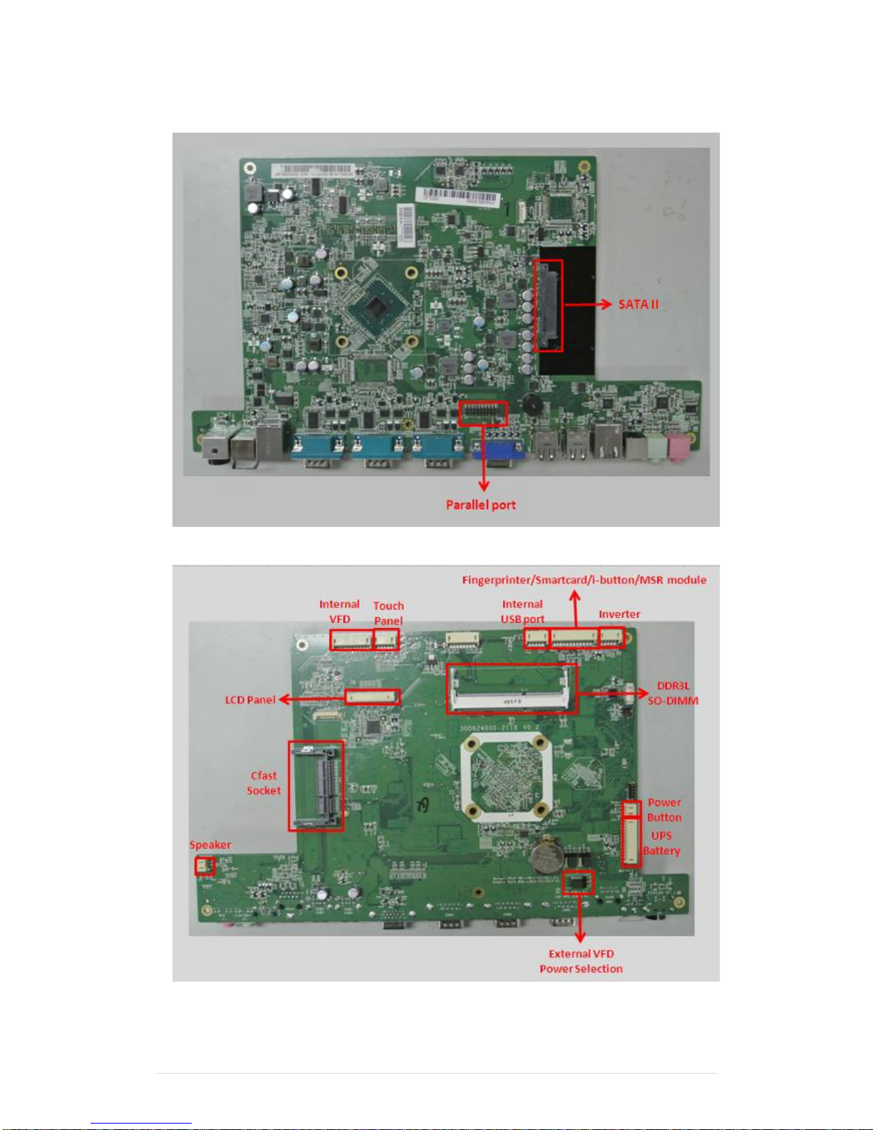
2-3 Internal Layout
Page 10
Clientron PT6100 User Manual
Version: 1.0
10 | 111
Pin Definition
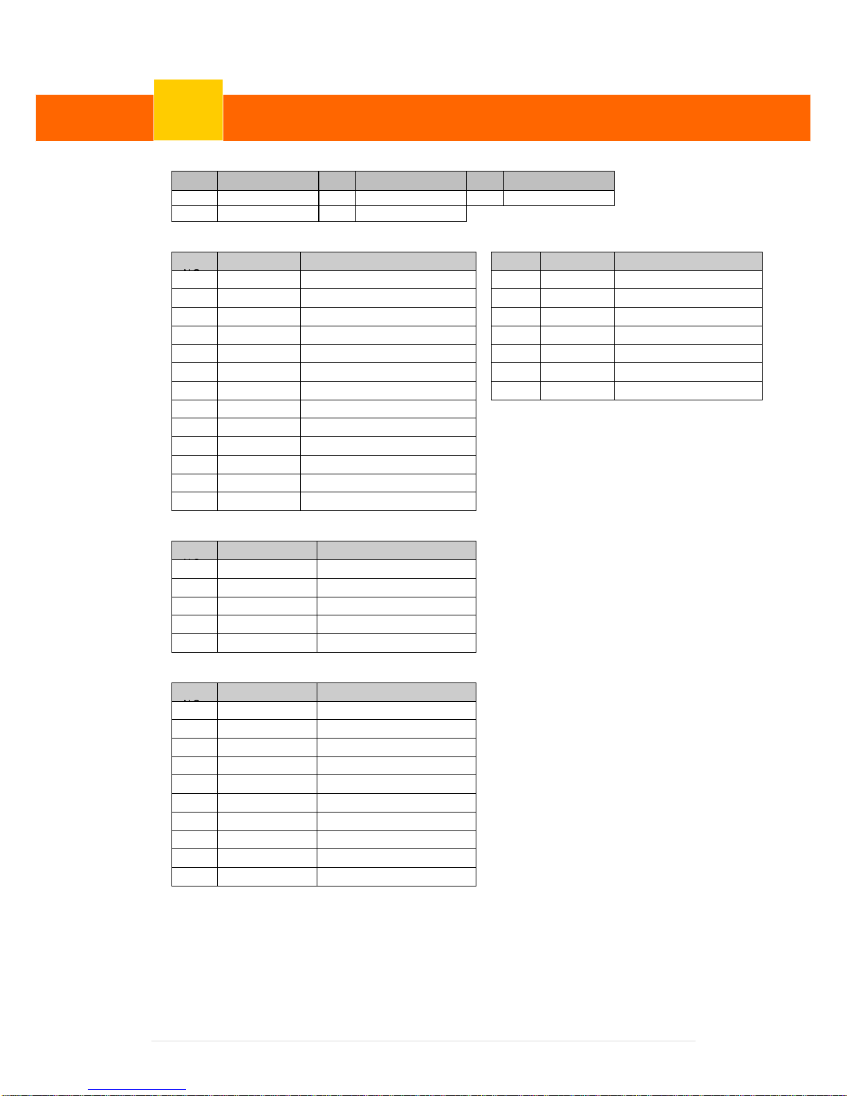
1. COM 5 for Touch Panel (CN 7)
Pin
Function
Pin
Function
Pin
Function
1
T_UR
3
T_SG
5
T_LR
2
T_UL
4
T_LL
2. Parallel J1
Pin
Pin Name
Description
Pin NO.
Pin Name
Description
1
STB#
Printer Strobe
14
AFD#
Printer Auto Line Feed
2
PD0
Parallel Port DATA0
15
ERR#
Printer Error
3
PD1
Parallel Port DATA1
16
INIT#
Printer Initialize
4
PD2
Parallel Port DATA2
17
SLIN#
Printer Select Input
5
PD3
Parallel Port DATA3
18
GND
Ground
6
PD4
Parallel Port DATA4
19
GND
Ground
7
PD5
Parallel Port DATA5
20
GND
Ground
8
PD6
Parallel Port DATA6
9 PD7
Parallel Port DATA7
10
ACK#
Printer Acknowledge
11
BUSY
Printer Busy
12
PE
Printer Paper End
13
SLCT
Printer Select
3. Line-out J2
Pin
Pin Name
Description
1
GND
Ground
2
GND
Ground
3
Line OUT R
Line out
4
Line OUT L
Line out
5
Detect
Detect
4. VFD Connector CN12
Pin
Pin Name
Description
1
5V
+5V
2
NDSR
DSR
3
GND
Ground
4
NDTR
DTR
5
NRTS
RTS
6
NCTS
CTS
7
NTXD
TXD
8
NRXD
RXD
9
GND
Ground
10
12C
+12V
Pin Definition
3
Page 11
Clientron PT6100 User Manual
Version: 1.0
11 | 111
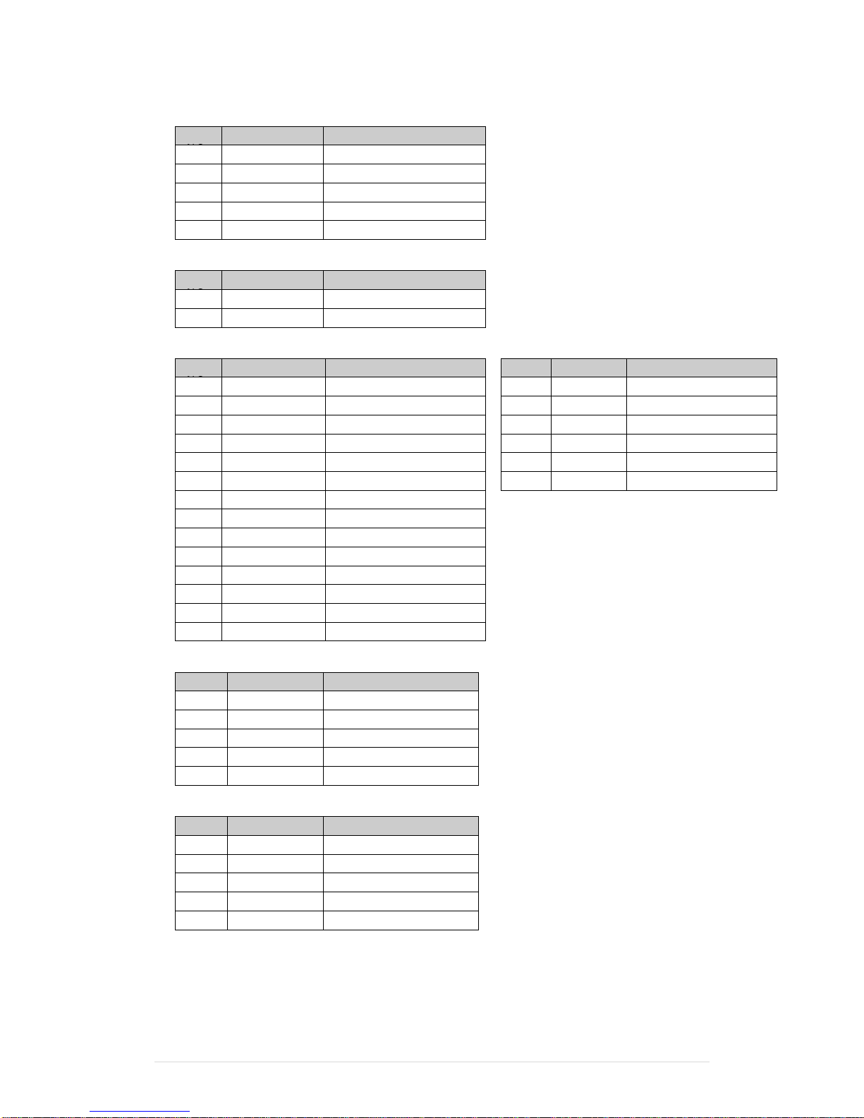
5. Mic J3
Pin
Pin Name
Description
1
GND
Ground
2
GND
Ground
3
Mic R
Mic
4
Mic L
Mic
5
Detect
Detect
6. Speaker SP1
Pin
Pin Name
Description
1 + Speaker +
2 - Speaker -
7. LVDS CN 13
Pin
Pin Name
Description
Pin NO.
Pin Name
Description
1
GND
Ground
15
DATA 0+
LVDS Output DATA0+
2
GND
Ground
16
DATA 0-
LVDS Output DATA0-
3
DATA 3+
LVDS Output DATA3+
17
GND
Ground
4
DATA 3-
LVDS Output DATA3-
18
GND
Ground
5
GND
Ground
19
LVDVCC
+3.3V
6
CLK+
LVDS CLK+
20
LVDVCC
+3.3V
7
CLK-
LVDS CLK-
8
GND
Ground
9
DATA 2+
LVDS Output DATA2+
10
DATA 2-
LVDS Output DATA2-
11
GND
Ground
12
DATA 1+
LVDS Output DATA1+
13
DATA 1-
LVDS Output DATA1-
14
GND
Ground
8. Inverter CN9
Pin NO.
Pin Name
Description
1
VCC
+12V
2
GND
Ground
3
NC
NC
4
BKL_CTL
Back Light Brightness
5
BKL_EN
Back Light Enable
9. Extra USB CN8
Pin NO.
Pin Name
Description
1
VCC
+5V
2
- DATA
D-
3
+ DATA
D+
4
GND
Ground
5
GND
Ground
Page 12
Clientron PT6100 User Manual
Version: 1.0
12 | 111
4
Rear I/O Interface
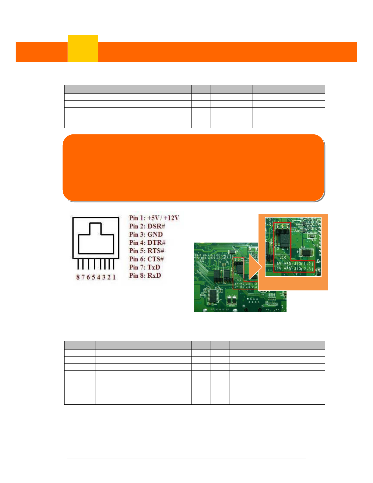
1. COM1’ COM2’ COM3 port
Pin
Signal
Function
Pin
Signal
Function
1
CD
Carrier Detect (IN)
6
DSR
Data Set Ready (In)
2
RD
Receive Data (IN)
7
RTS
Request To Send (OUT)
3
TD
Transmit Data(OUT)
8
CTS
Clear To Send (IN)
4
DTR
Data Terminal Ready(OUT)
9
Ring/5V/12V
Setting by BIOS
5
GND
Ground
Jumper for COM4
Voltage Setting
2. VGA port
Pin
I/O
Function
Pin
I/O
Function
1
Out
Red Video
9 - Key (Plugged Hole)
2
Out
Green Video
10 - Sync Ground
3
Out
Blue Video
11
In
Monitor ID 0
4
In
Monitor ID 2
12
In
Monitor ID 1
5 - TTL Ground (Monitor Self Test)
13
Out
Horizontal Sync
6 - Red Analogue Ground
14
Out
Vertical Sync
7 - Green Analogue Ground
15
In
Monitor ID 3
8 - Blue Analogue Ground
Rear I/O Interface
4
NOTICE:
☆ COM 4 port. Warning!! COM4 (RJ45 Connector) for external VFD use only. Never
use on network device. If you are using on the network device will cause the
device damaged.
☆☆ COM 4 port will be inactive if POS has internal VFD. (Alternative of COM 4 or internal
VFD)
Enlarge JUMP
Page 13
Clientron PT6100 User Manual
Version: 1.0
13 | 111
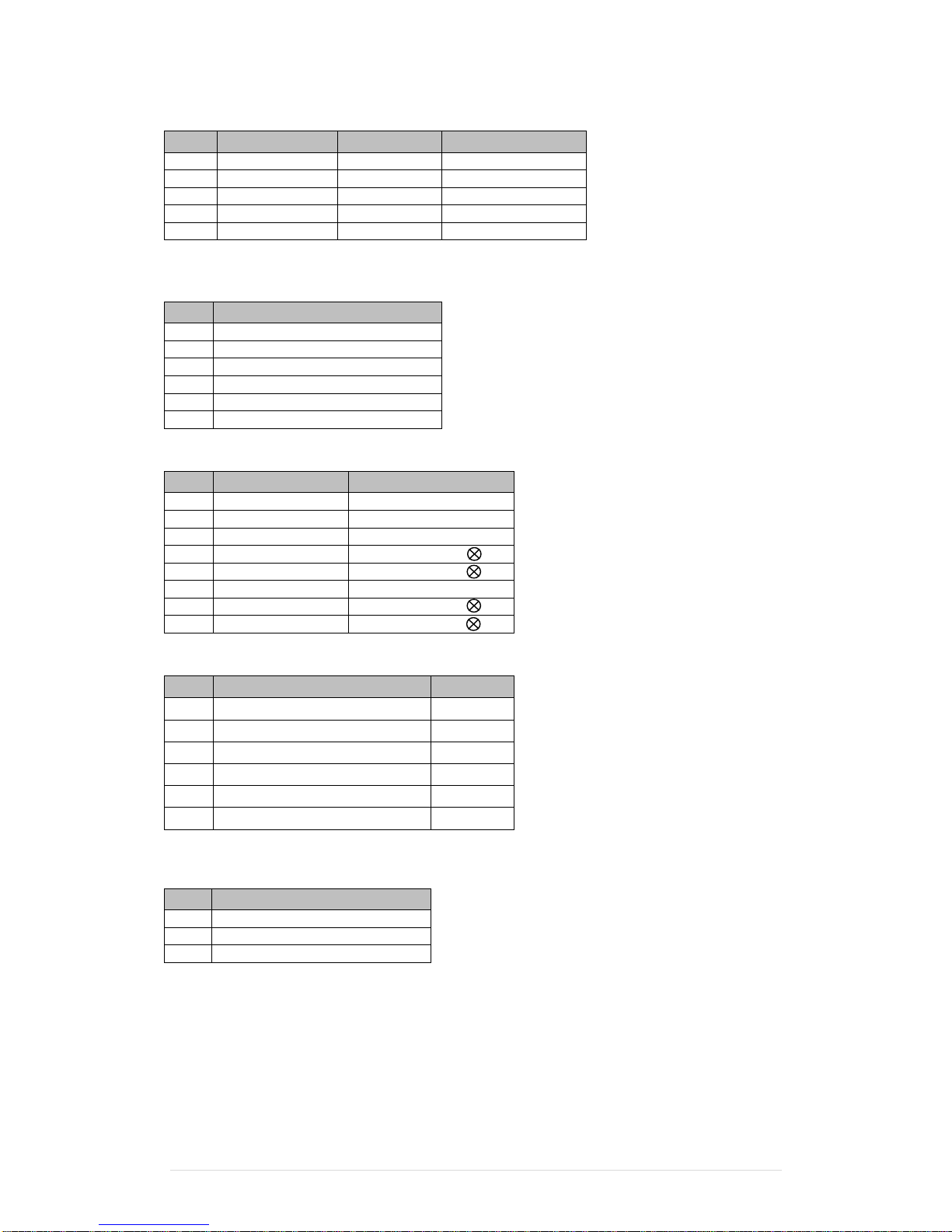
3. USB port
Pin
Signal Name
Wire Colour
Comment
1
VCC
Red
Cable Power
2
- Data
White
Data Transfer
3
+ Data
Green
Data Transfer
4
Ground
Black
Cable Ground
Shell
Shield
-
Drain Wire
4. PS/2 K/B port
Pin
Signal Name
1
Data from Device
2
Not Connected
3
Ground
4
+5V DC
5
Clock
6
Not Connected
5. LAN port
Pin
Wire Colour
Description
1
White / Orange
Transmit
2
Orange
Transmit
3
White / Green
Receive
4
Blue
Not Used
5
White / Blue
Not Used
6
Green
Receive
7
White / Brown
Not Used
8
Brown
Not Used
6. RJ11 port (for Cash drawer)
Pin
Signal Name
Direction 1 Frame GND
-
2
Drawer Kick-out drive signal 1
Output 3 Cash Drawer Status
Input 4 +12V
-
5
N/C
-
6
Signal GND
-
7. DC Jack
Pin
Signal Name
1
DC IN 19V
2
Ground
3
DC IN 19V
Example DOS COMMAND for Cash Drawer:
1. Create the file: TEST.TXT
2. Input below contents in TEST.TXT
CONTEXT-"000.0”
MODE COM6:300
3. Run COMMAND under DOS mode
COPY TEST.TXT COM6
Page 14
Clientron PT6100 User Manual
Version: 1.0
14 | 111
5
System Assembly & Disassembly
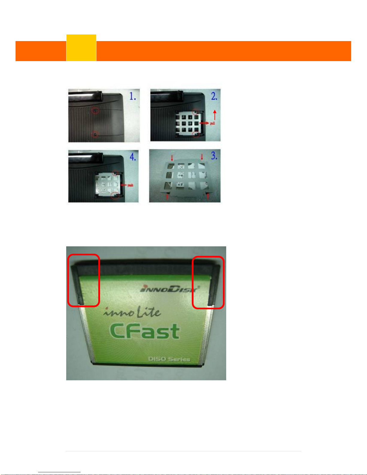
5-1 HDD
1. Unfasten the HDD
cover screw*2
2. Pull out the HDD
bracket
3. Fasten the screw*4
4. Place the HDD
bracket back to the
module
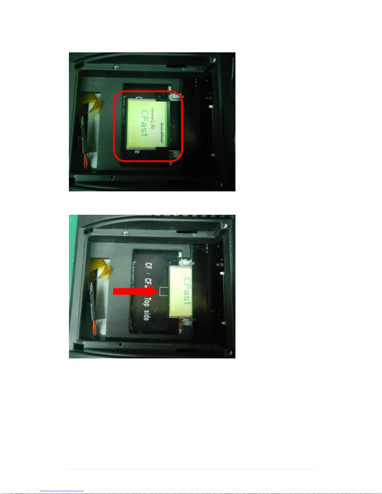
5-2 CFast Card
1. Please notice the unnotched CFast Card . This side up.
UP
System Assembly & Disassembly
5
Page 15
Clientron PT6100 User Manual
Version: 1.0
15 | 111
2. Before Installing CFast Card.
3. After Installing CFast Card
Page 16
Clientron PT6100 User Manual
Version: 1.0
16 | 111
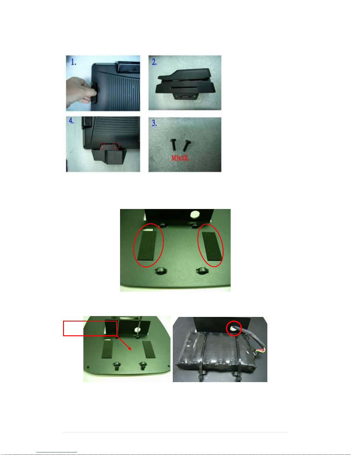
5-3 MSR
1. Open the MSR cover
2. Single MSR or 3-in-1
MSR
3. Screw*2 M3x10L
4. Fasten the screw
5-4 UPS Battery
1. Paste two rubbers on the located position of the Stand Bracket.
2. Reeve two cable ties through the stand bracket. Place the battery pack in position and
bind the cable ties tightly. Then cut the extra tail from cable ties.
3. Reeve the cable from the battery pack through the stand bracket.
Positioning hole
Page 17
Clientron PT6100 User Manual
Version: 1.0
17 | 111
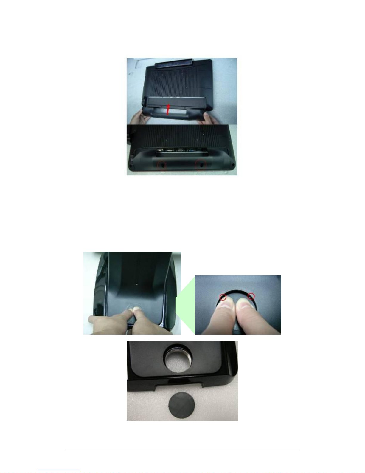
5-5 cable cover
Assemble the cable cover from bottom and make sure the two latches are on the right position.
Then fasten 2 screws (M3*5L).
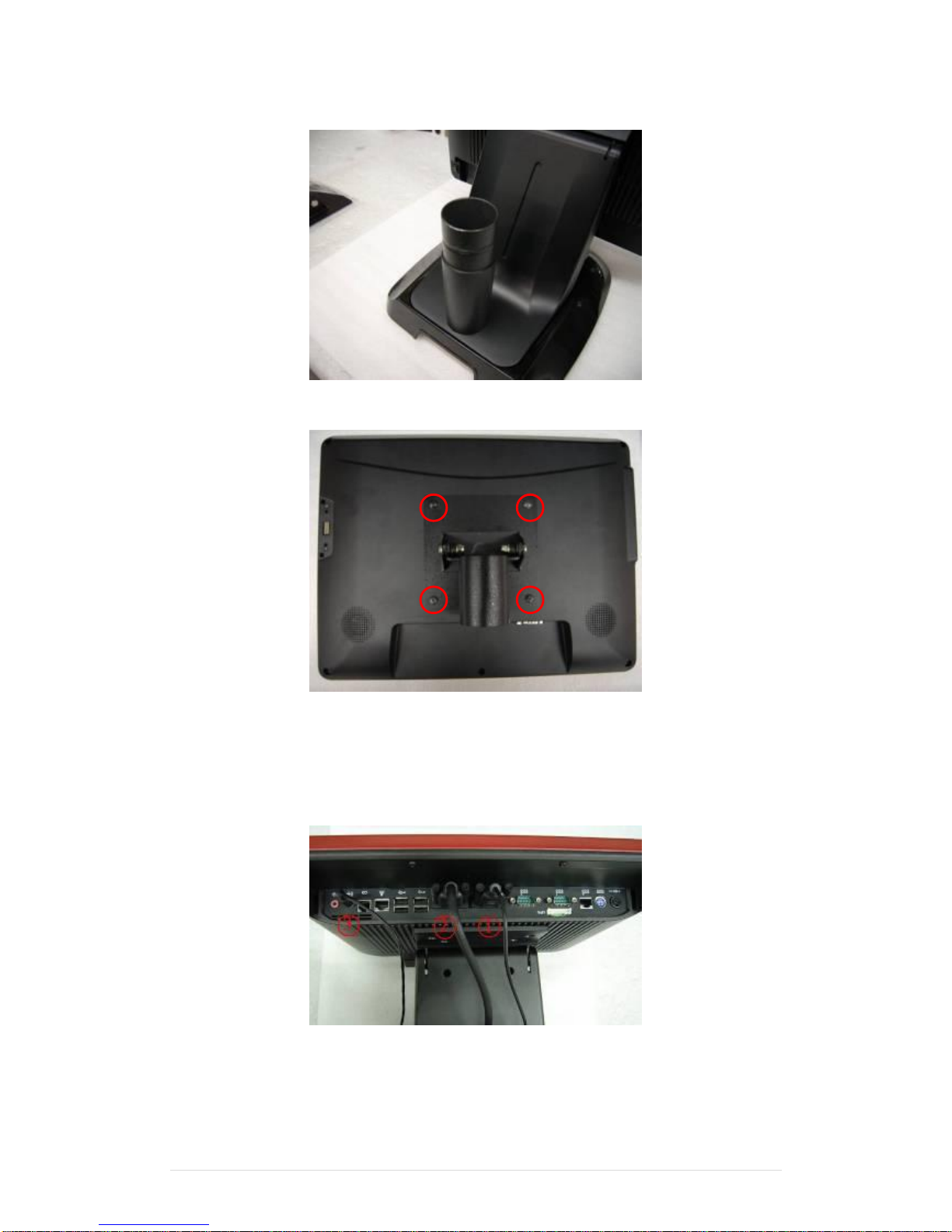
5-6 15” 2nd Display
☆ Power supply must be replaced to 120W above power adapter.
1. Remove the plastic pole cover from the stand.
Page 18
Clientron PT6100 User Manual
Version: 1.0
18 | 111
2. Install the pole into the socket in clockwise direction.
3. Fasten the four screws (M4*8L) to joint the VESA bracket and the rear cover.
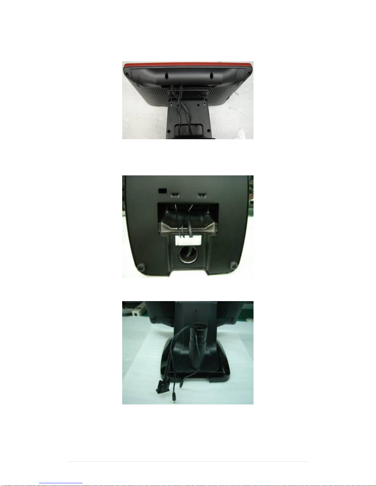
4. Connect the COM port, DC cable as shown in figure . (Please refer to page 107 to set
the COM port pin9 with 12V DC output.)
5. Connect the VGA cable as shown in figure .
6. Connect the audio cable as shown in figure.
Page 19
Clientron PT6100 User Manual
Version: 1.0
19 | 111
7. Assemble the cable cover from bottom and make sure the two latches are on the right
position, and fasten the two screws (M3*5L).
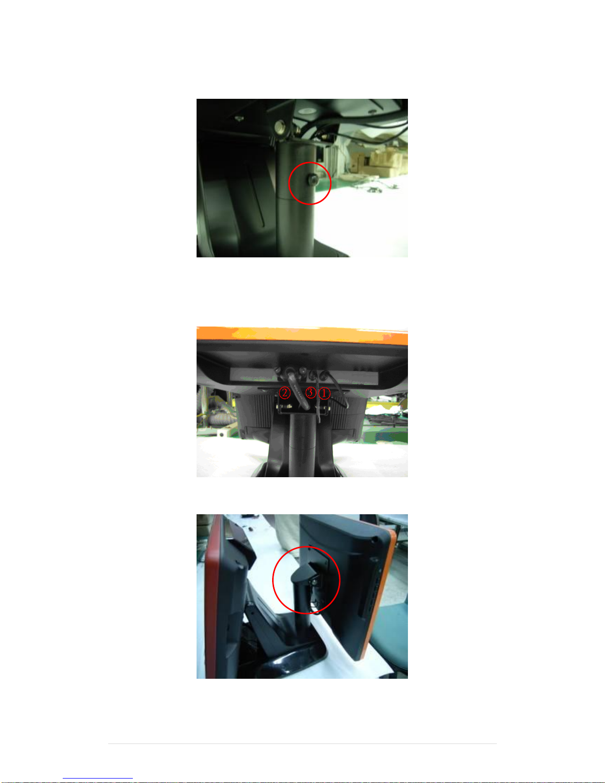
8. Route the cables through the opening of stand front cover and cable clip at the bottom
and route the cables into the tube of pole.
9. Reeve the cables out of the tube.
Page 20
Clientron PT6100 User Manual
Version: 1.0
20 | 111
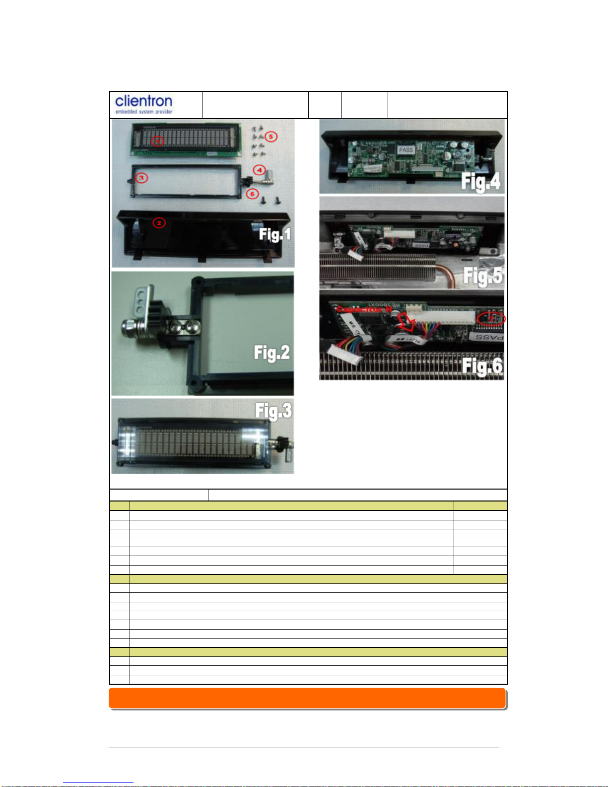
10. Mount the VESA bracket on the pole and route cables out of the tube of VESA bracket.
Fasten the thumb screw to fix the VESA bracket.
11. Connect the DC power cable as shown in figure.
12. Connect the VGA cable as shown in figure.
13. Connect the Audio cable as shown in figure.
14. Put the cable cover on the hinge of VESA bracket.
Page 21
Clientron PT6100 User Manual
Version: 1.0
21 | 111
5-7 Internal VFD
Clientron electronics
Inc.
Model
PT6100
Assembling Figure
Operation
VFD MODULE assemblely
Item
Operation procedure
Remark
1
Prepare all components as Fig 1
2
Assemble holder & hinge assy by TAPPING SCREW P/H 2.6φ*5 x2 pcs(As Fig 2)
Torque 2Kgf
3
Fix VFD module on holder assy by TAPPING SCREW P/H 2.6φ*5 x4 pcs as Fig 3
Torque 2Kgf
4
Screw VFD module on VFD cover by TAPPING SCREW P/H 2.6φ*5 x 2pcs AS fig 4)
Torque 2Kgf
5
Fix VFD module on rear cover by TAPPING SCREW R/H M3*8L x 2pcs (As Fig 5)
Torque 2Kgf
6
The VFD cable must be around to capacitor H below, so as not to interfere hinge action
(As Fig 6)
Item
P/N and Component
1
20D990002-000B DISPLAY MODULE VFD *1
2
68D350235-000B COVER FOR VFD *1
3
78D300021-000B HOLDER FOR VFD *1
4
26D100005-000B HINGE ASSY FOR VFD *1
5
64D426051-000T SCREW TAPPING P/H 2.6φ*5 *8
6
64D430088-000T SCREW TAPPING R/H M3*8L *2
7
35D510480-000B CABLE 16P femail TO 8P female*1
Item
Action item
1
Wear cotton gloves, wrist strap and may not wear watches, rings, etc.
2
Screws to lock in place and can not lost
3
Electric screwdriver Torque to be regularly calibrated,
☆ Alternative of external COM4 (RJ45 Connector) or Internal VFD.
Page 22
Clientron PT6100 User Manual
Version: 1.0
22 | 111
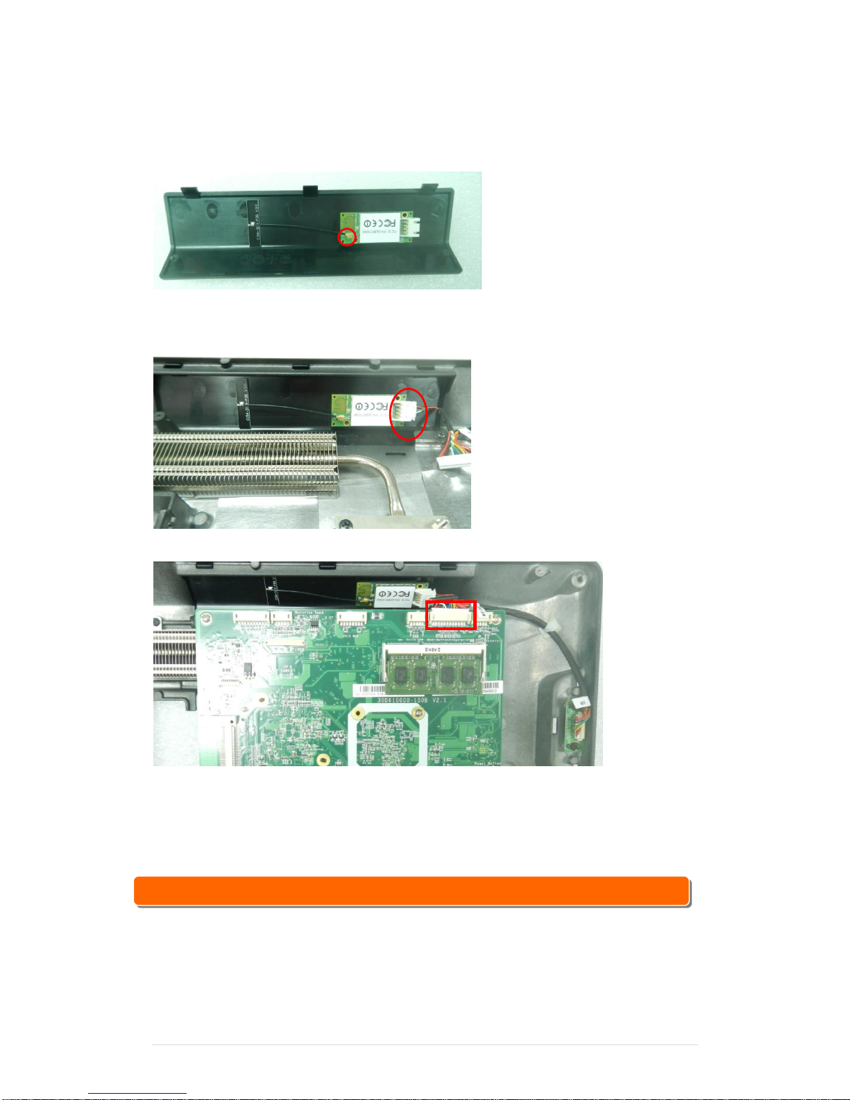
5-8 Wi-Fi
1. Connect the antenna to Wi-Fi module, fastening the Wi-Fi Module to the Rubber , then
fasten WI-Fi Module and antenna on VFD cover.
2. Assemble VFD cover and Back panel with 2 screws. Then connect Wi-Fi /MSR cable to
Wi-Fi module
3. Connect Wi-Fi /MSR cable to M/B
☆ Alternative of WiFi or Internal VFD.
Page 23
Clientron PT6100 User Manual
Version: 1.0
23 | 111
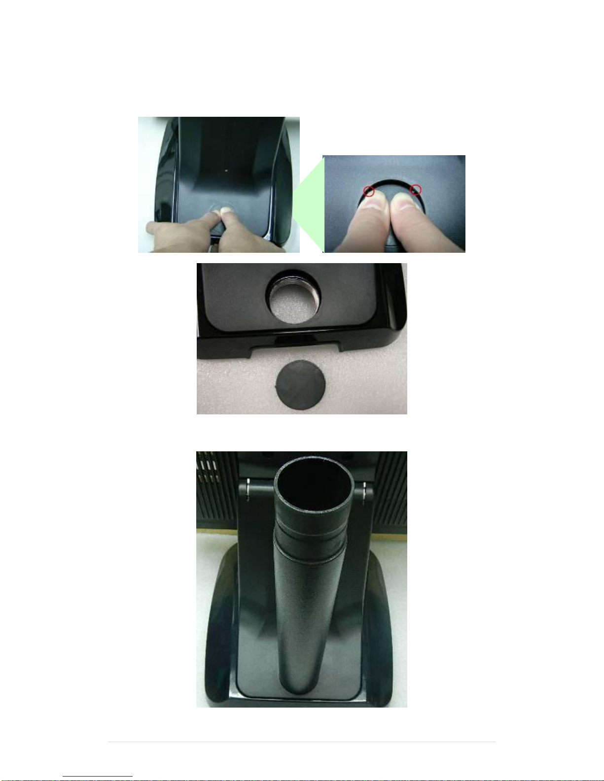
5-9 8” 2nd Display
1. Remove the plastic pole cover from the stand.
2. Install the pole into the socket in clockwise direction.
Page 24
Clientron PT6100 User Manual
Version: 1.0
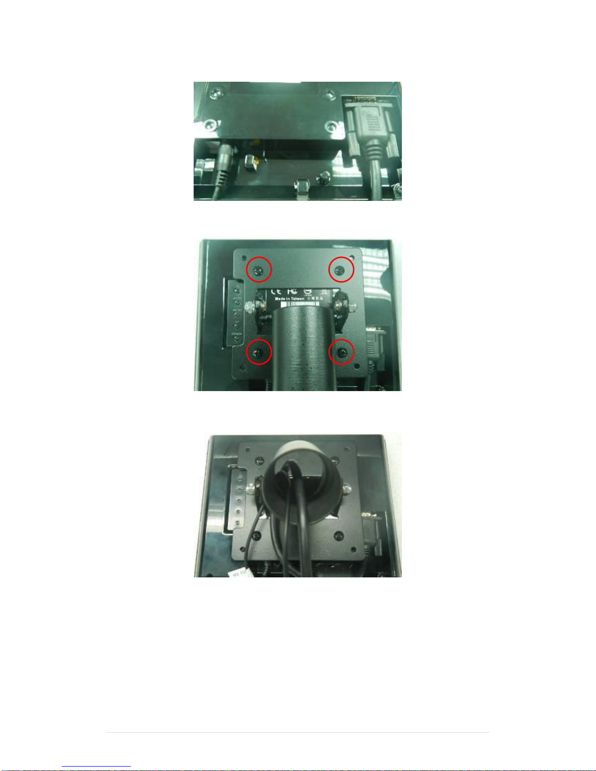
24 | 111
3. Connect VGA cable and DC power cable
4. Fasten the four screws (M4*8L) to joint the VESA bracket and the rear cover.
5. Reeve the cables out of the tube.
Page 25
Clientron PT6100 User Manual
Version: 1.0
25 | 111
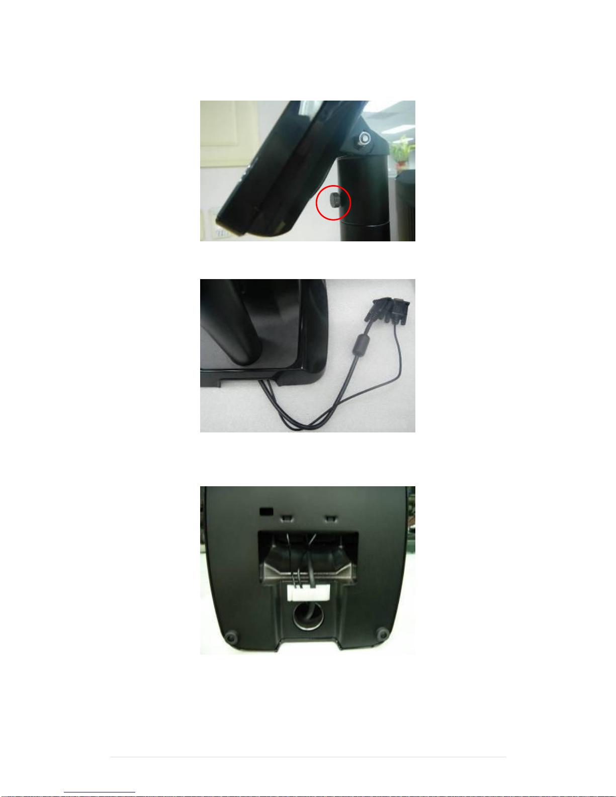
6. Mount the VESA bracket on the pole and route cables out of the tube of VESA bracket.
Fasten the thumb screw to fix the VESA bracket.
7. Reeve the cables out from the bottom of pole.
8. Route the cables through the opening of stand front cover and cable clip at the bottom
and route the cables into the tube of pole.
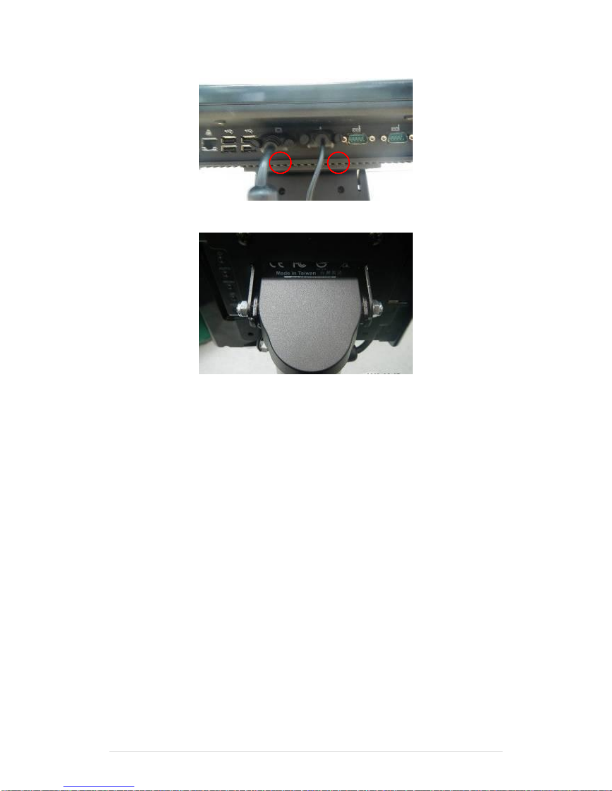
9. Connect the DC power cable as shown in figure.
☆ To setup COM port PIN9 with 12V DC output from BIOS setup, please refer to page 74,
Advanced Chipset Features / COM port PIN9 setting.
Page 26
Clientron PT6100 User Manual
Version: 1.0
26 | 111
10. Connect the VGA cable as shown in figure.
11. Put the cable cover on the hinge of VESA bracket.
2
1
Page 27
Clientron PT6100 User Manual
Version: 1.0
27 | 111
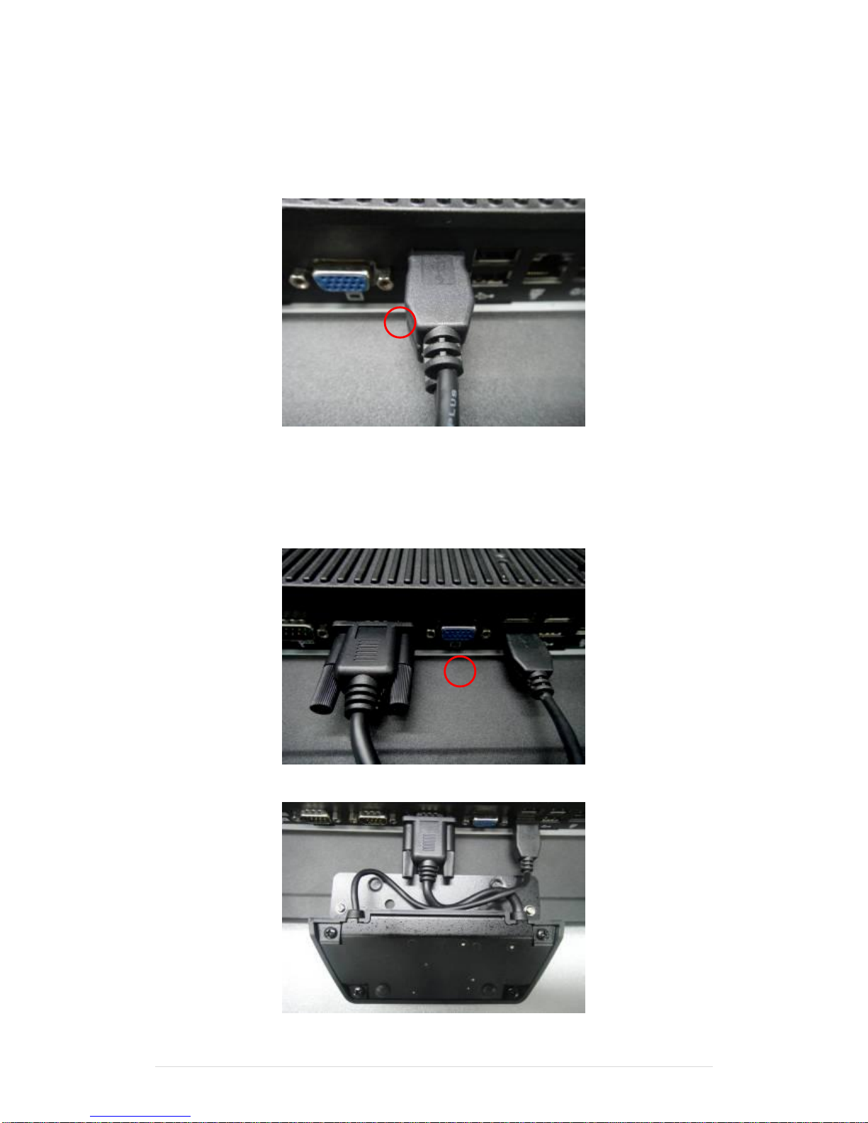
5-10 1D / 2D / i-Button with RFID module
1. Cable installation.
a. For i-Button with RFID module; For 2D barcode scanner with RFID module:
Connect the cable as shown in figure.
b. For 1D barcode scanner with RFID module:
Connect the cable as shown in figure.
☆ Before COM port cable connection, please setup COM port PIN9 with 5V DC output
from BIOS setup.
Please refer to page 74, Advanced Chipset Features / COM port PIN9 setting.
2. Fix the screws as shown in below figure.
1
2
Page 28
Clientron PT6100 User Manual
Version: 1.0
28 | 111
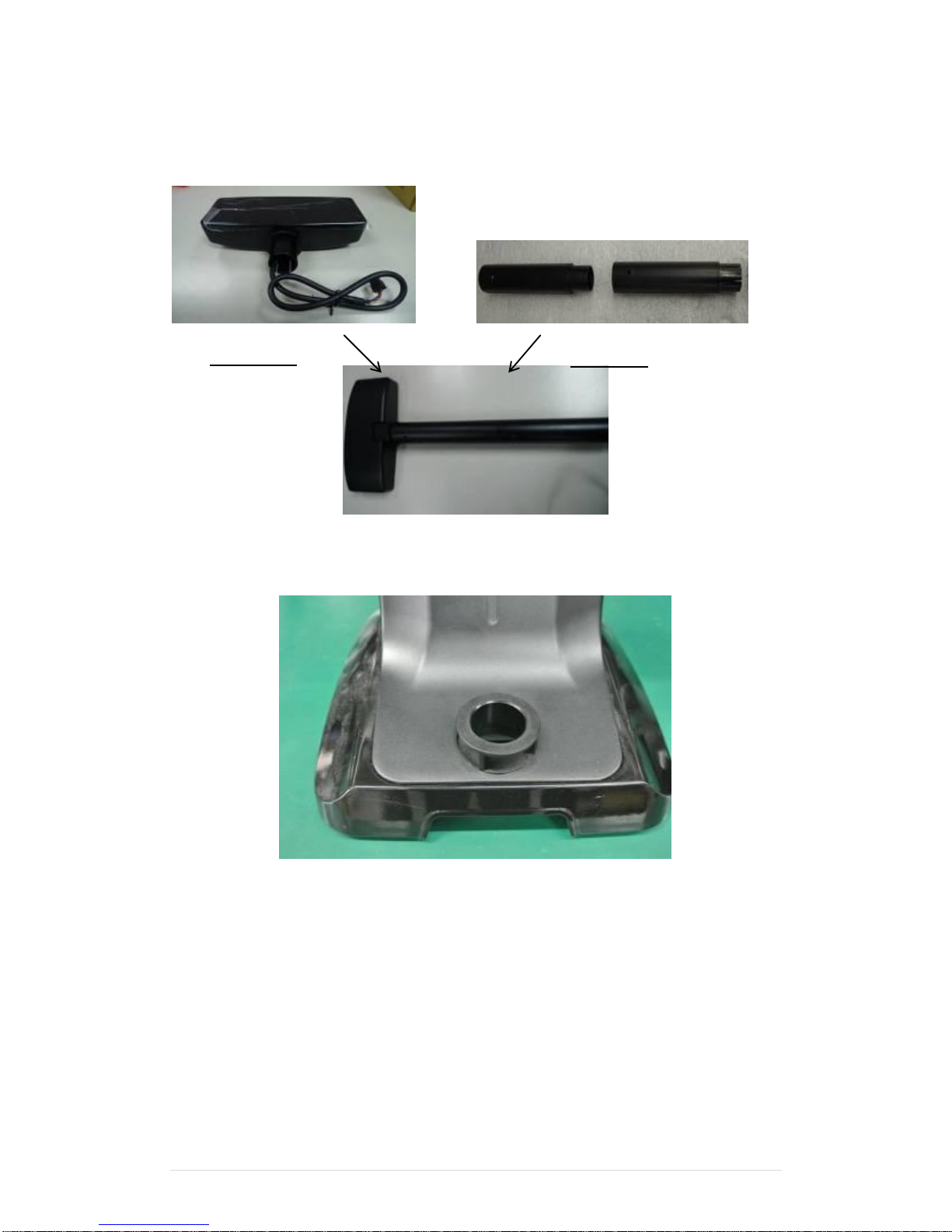
5-11 Pole type VFD VD1220
1. Take VFD panel and two VFD poles out from the package box and Install two tubes into one
pole and reeve the cable from the VFD panel through the socket of stand.
2 For the foot ring assembly, please install the foot ring into the socket in clockwise
direction.
VFD Panel
VFD Pole
Page 29
Clientron PT6100 User Manual
Version: 1.0
29 | 111
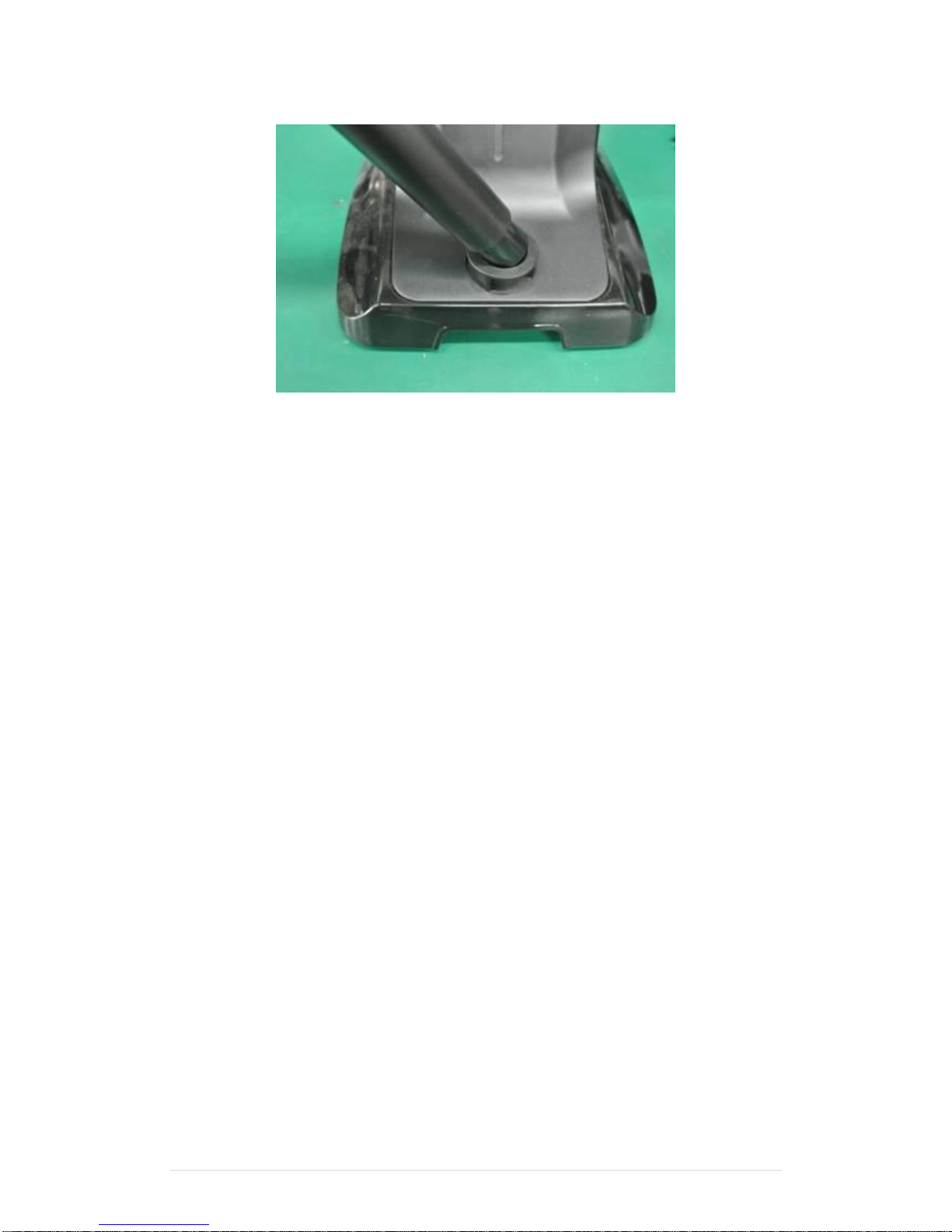
3 Then install the pole into the foot ring.
4 Then connect RJ45 cable to POS terminal’s RJ45 port
Page 30
Clientron PT6100 User Manual
Version: 1.0
30 | 111
Device Driver Installation
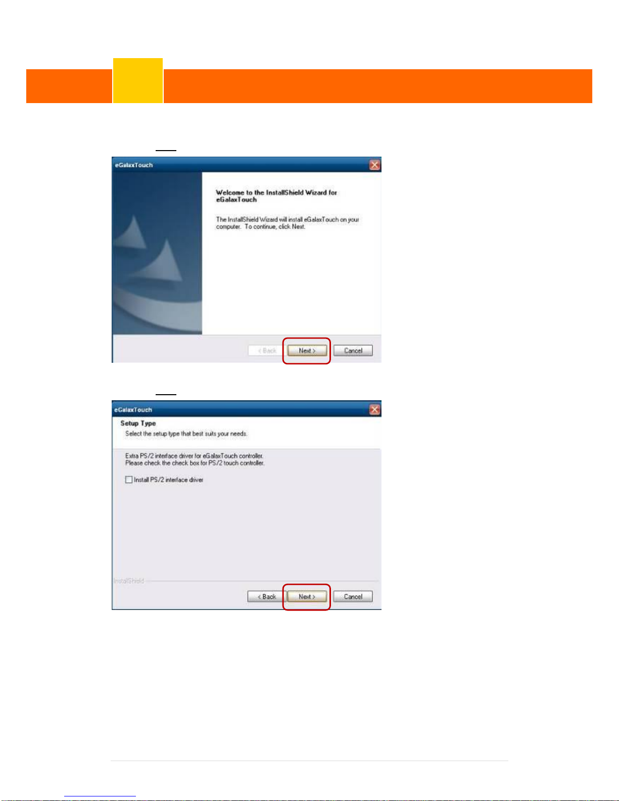
6-1. Resistive Type Touch Panel and P-CAP
1. Click “Next”.
2. Click “Next”.
Device Driver Installation
6
Page 31
Clientron PT6100 User Manual
Version: 1.0
31 | 111
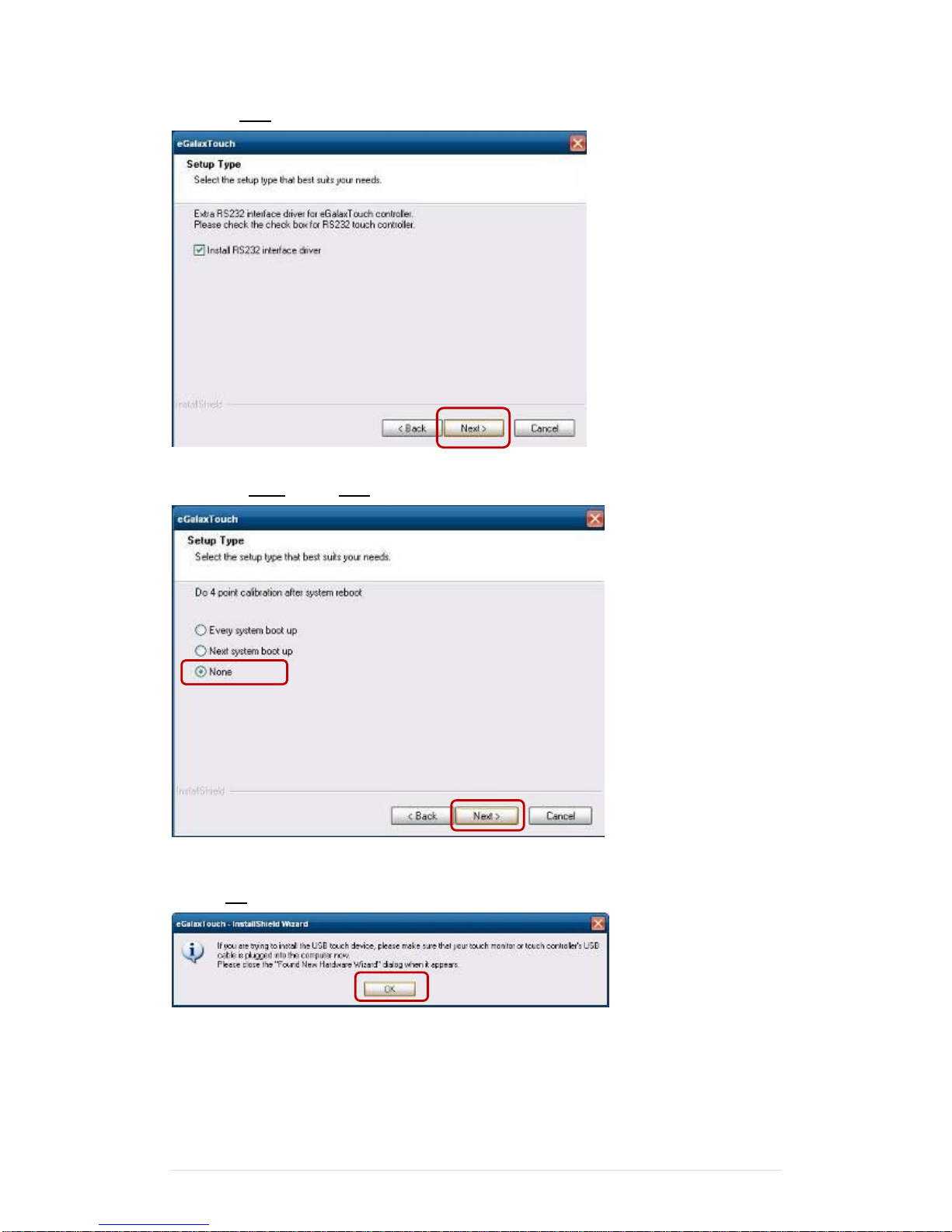
3. Click “Next”.
4. Select “None”, Click “Next”.
5 Click “OK”.
Page 32
Clientron PT6100 User Manual
Version: 1.0
32 | 111
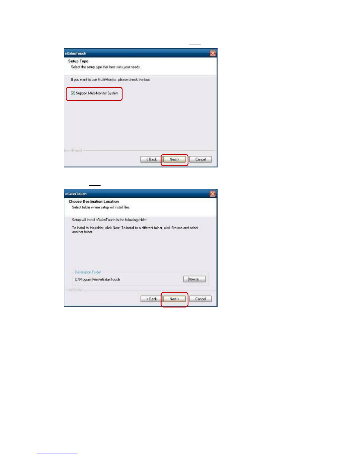
6. Select “Support Multi-Monitor System”, Click “Next”.
7. Click “Next”.
Page 33
Clientron PT6100 User Manual
Version: 1.0
33 | 111
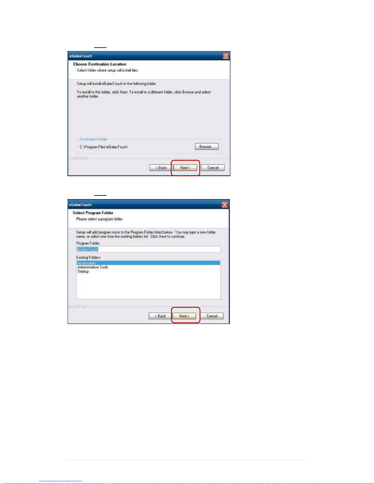
8. Click “Next”.
9. Click “Next”.
Page 34
Clientron PT6100 User Manual
Version: 1.0
34 | 111
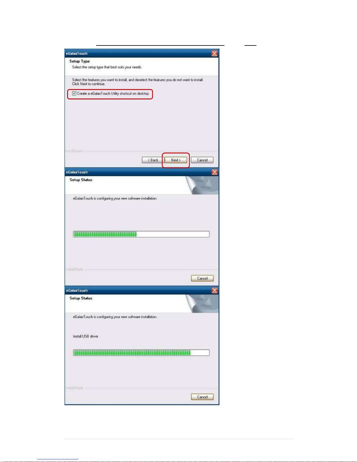
10. Select “Create a eGalaxTouch Utility shortcut on desktop”, Click “Next”.
Page 35
Clientron PT6100 User Manual
Version: 1.0
35 | 111
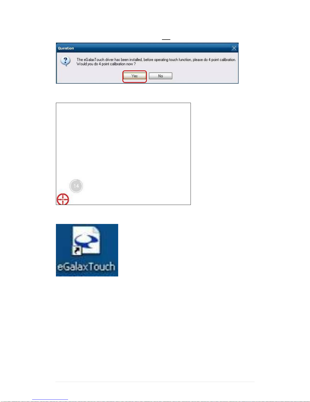
11. Would you do 4 point calibration now? Click “Yes”.
12. Do 4 points aligrment to match display.
13. Calibration utility.
Page 36
Clientron PT6100 User Manual
Version: 1.0
36 | 111
6-2 MagStripe Card Reader Configuration Utility
1. Combo USB HID MSR
The MagStripe Card Reader Configuration Utility is used to set up the output format of
HIDMSR-20
Installation
Below steps guide you how to install the Utility program
Insert the setup CD
Run the HIDMSR-20 Utility.exe setup file that is located in the Software folder of CD.
Follow the wizard to complete the installation.
Launching Program
Below steps guide you how to load the Utility program.
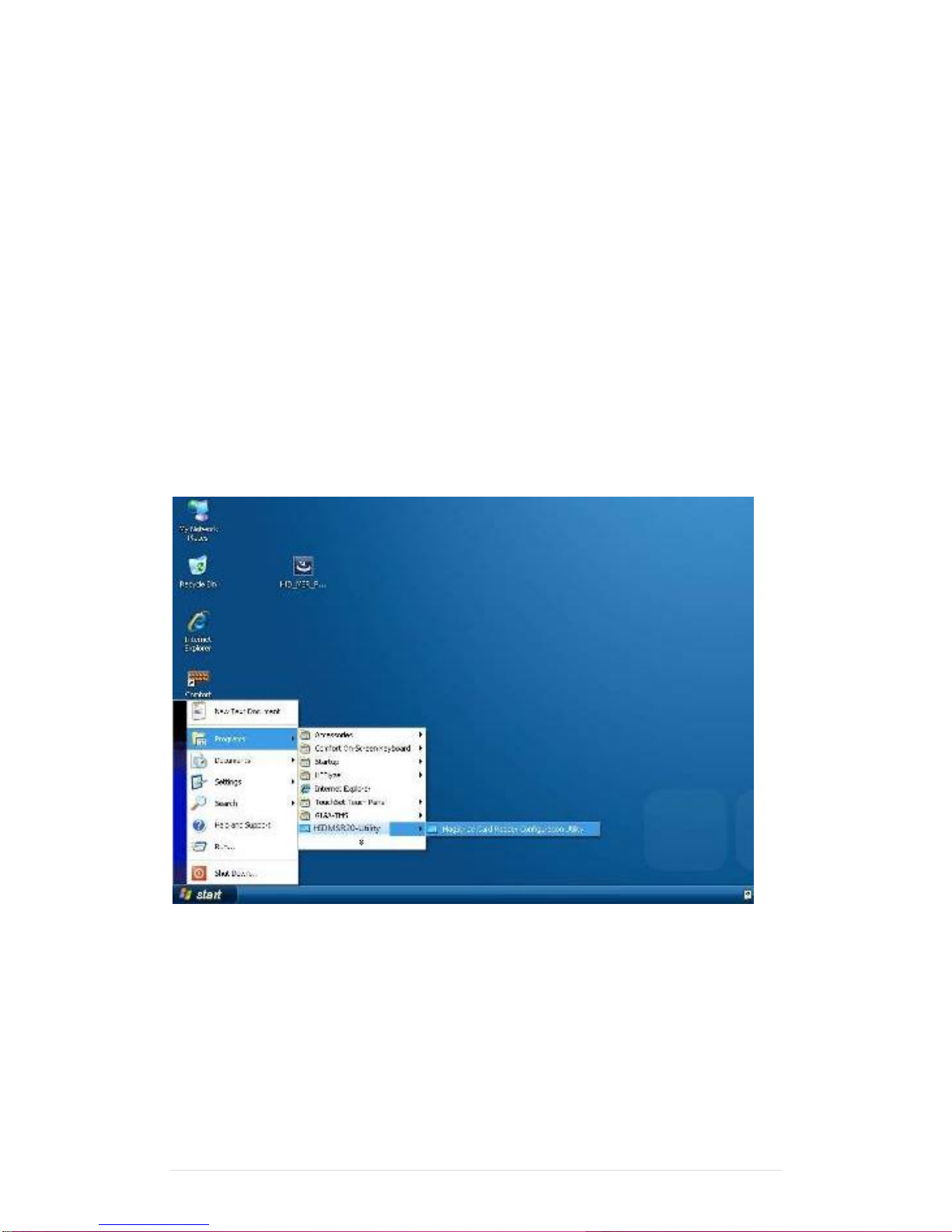
From Start/Programs, click HIDMSR20 folder
Click MagStripe Card Reader Configuration Utility to launch the program.
The utility program will detect the connected reader. If detected, all the input text boxes
will be enabled.
If the reader has not been connected to PC yet, please connect the reader and then click
Refresh to get connected.
Page 37
Clientron PT6100 User Manual
Version: 1.0
37 | 111
Configuration
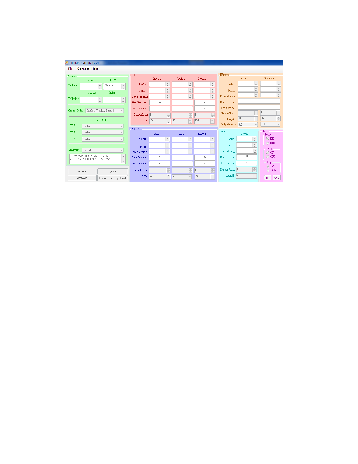
Below is the main window of Utility program.
For the settings, there are:
Language: The language defines the code positions of the keyboard. Each language
should use its own settings. Wrong language selected will cause the wrong character
displayed.
Prefix/Suffix: Defines the data string which you would like to append in front or end of
the MSR data string.
Error Message: Indicates which track number cause the error.
Delimiter: Indicates the swipe result.
ISO: Define start and end sentinel character.
Decode Mode: Determines the way of outputting the three tracks data.
Page 38

Clientron PT6100 User Manual
Version: 1.0
38 | 111
Shown below is the data structure of the output string for MSR.
PP
PR1
SS1
TK1
ES1
SU1
PR2
SS2
TK2
ES2
SU2
PR3
SS3
TK3
ES3
SU3
SU
DM
PP: Prefix for package.
PR1: Prefix for track 1.
SS1: Start sentinel for track 1.
TK1: Data for track 1, if error happens, using Error Message instead.
ES1: End sentinel for track 1.
SU1: Suffix for track 1.
PR2: Prefix for track 2.
SS2: Start sentinel for track 2.
TK2: Data for track 2, if error happens, using Error Message instead.
ES2: End sentinel for track 2.
SU2: Suffix for track 2.
PR3: Prefix for track 3.
SS3: Start sentinel for track 3.
TK3: Data for track 3, if error happens, using Error Message instead..
ES3: End sentinel for track 3.
SU3: Suffix for track 3.
SU: Suffix for package.
DM: Delimiter for the swipe result.
Prefix/Suffix
In default, the prefix and suffix settings are all keep blank. There are 4 kinds of prefix and suffix
to be defined, which are:
Package: For the prefix string, it is appended in the front of the whole MSR data. For the
suffix, it is appended in the end of the whole MSR data. In most case, the suffix for package is
always to be the “Enter” or “Tab” character. The max data length of the prefix and suffix for the
package can be up to 127.
TK1: For the prefix string, it is appended in the front of the start sentinel of track 2. For
the suffix, it is appended in the end of the end sentinel of track 2. The max data length of the
prefix and suffix for the TK1 can be up to 127.
TK2: For the prefix string, it is appended in the front of the start sentinel of track 2. For
the suffix, it is appended in the end of the end sentinel of track 2. The max data length of the
prefix and suffix for the TK1 can be up to 127.
TK3: For the prefix string, it is appended in the front of the start sentinel of track 3. For
the suffix, it is appended in the end of the end sentinel of track 3. The max data length of the
prefix and suffix for the TK1 can be up to 127.
Page 39
Clientron PT6100 User Manual
Version: 1.0
39 | 111
ISO
This group defines the start and end sentinel for each track. The sentinel is always used to
extract the track data from the whole MSR data string. The data length for each sentinel is
fixed to one character. Because there is ISO standard that defining the start and end sentinel
for the three tracks. For the compatible reason, please do not modify the default value if
possible.
Decode Mode
For this group, it contains two kinds of settings, which are:
Track Data Filtering: Determine which track to be, not to be output or needed to be
output.
Switch Output Order: Change the output order of track 1 ~ 3.
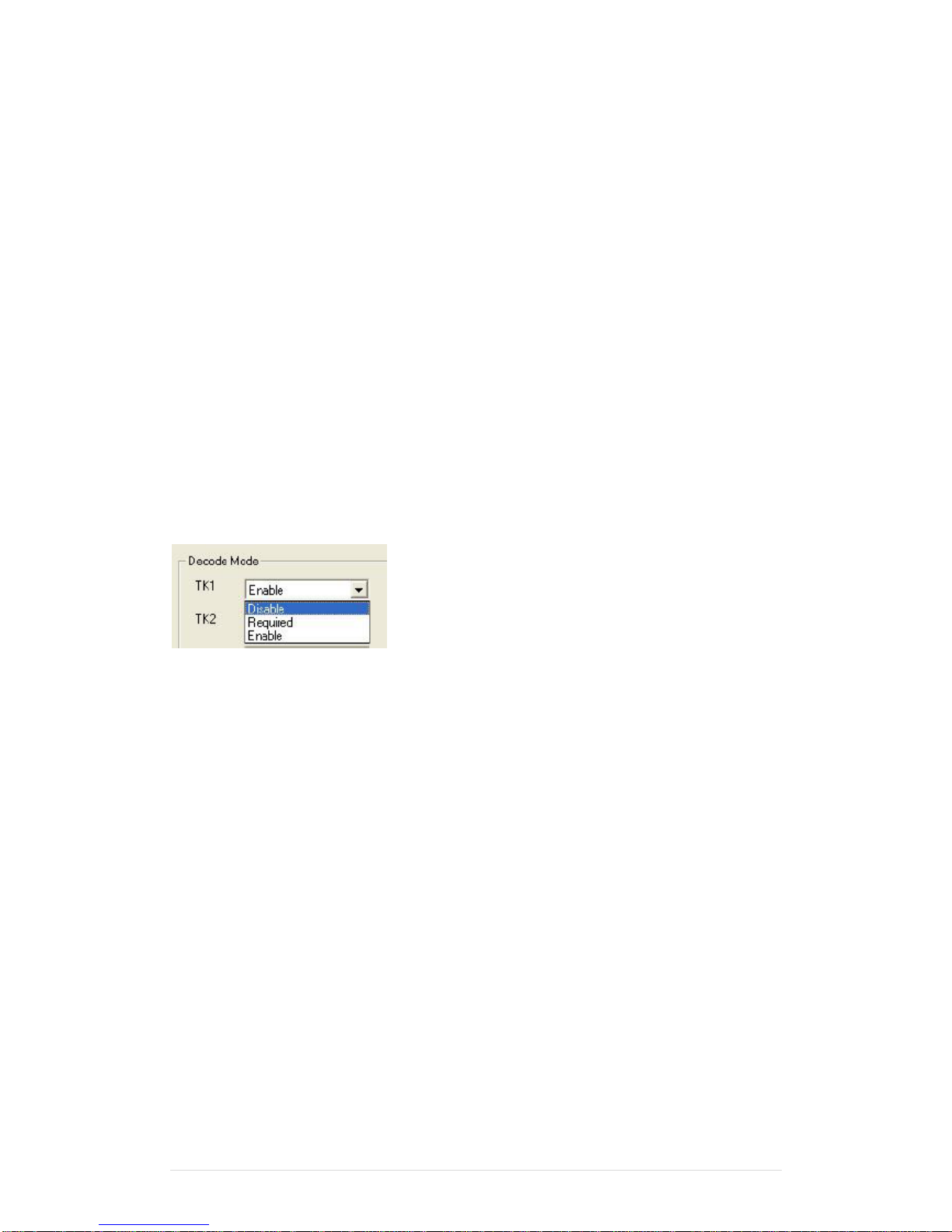
Track Data Filtering
Shown below is the filter setting for track 1. This provides a fool-proofing method in case of
receiving unwanted or uncompleted track data.
These three filter settings are:
Enable: If selected, the data of specified track will be packaged in the MSR data string. If
the specified track data is not decoded, it will leave blank in the MSR data string.
Required: If selected, which means the output MSR data string must contain the
specified track data. If the specified track data is not decoded, even MSR data string contains
other track data, it will still not to be output.
Disable: If selected, the data of specified track will not be packaged in the MSR data
string. No matter it is decoded or not.
Page 40
Clientron PT6100 User Manual
Version: 1.0
40 | 111
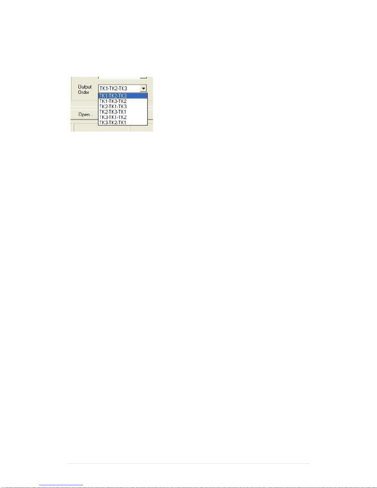
Switch Output Order
Show below is the selection of the three track data output order (sequence). The default order
is Track 1–Track 2–Track 3.
There 6 orders allow to be selected. Please select one to fit your application needs.
Update Settings
Once complete the settings, click Update to update the settings to connected HID MSR
reader.
Save Settings
To save the settings to a file, click Save; specify the file name and location to be saved.
Open Settings
To load pre-saved settings, click Open, specify the settings file, and then click OK to load into
program.
Restore MSR Reader Settings
To load restore settings of connected MSR reader, click Restore ES2: End sentinel for track.
Page 41
41 | 111
2. SINGLE MSR
The MagSwipe Configuration Utility is used to set up the output format of MagSwipe
Installation
Below steps guide you how to install the Utility program
Insert the setup CD
Run the 80066804-006_Magswipe_Configuration_Software_V2_1_A setup file that is
located in the Software folder of CD.
Follow the wizard to complete the installation.
Launching Program
Below steps guide you how to load the Utility program.
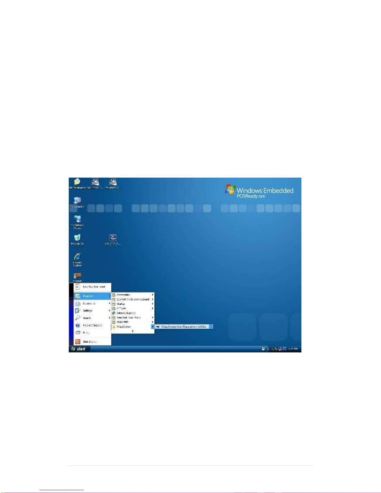
From Start/Programs, click MagSwipe folder
Click MagSwipe Configuration Utility to launch the program.
Page 42
Clientron PT6100 User Manual
Version: 1.0
42 | 111
Configuration
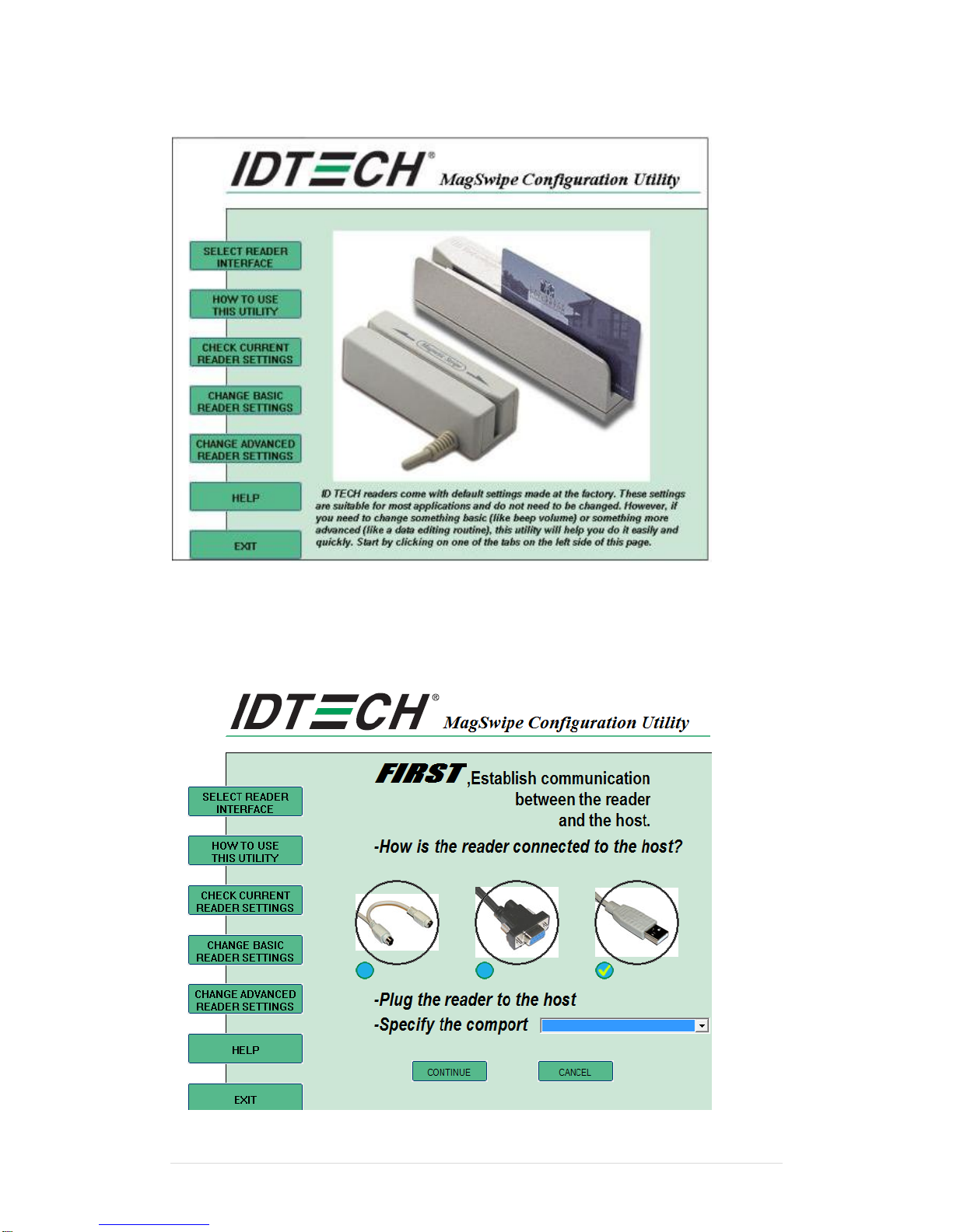
Select Reader Interface
The reader to be configured should be connected. Select the corresponding connected reader
interface and click the Continue button
Page 43
Clientron PT6100 User Manual
Version: 1.0
43 | 111
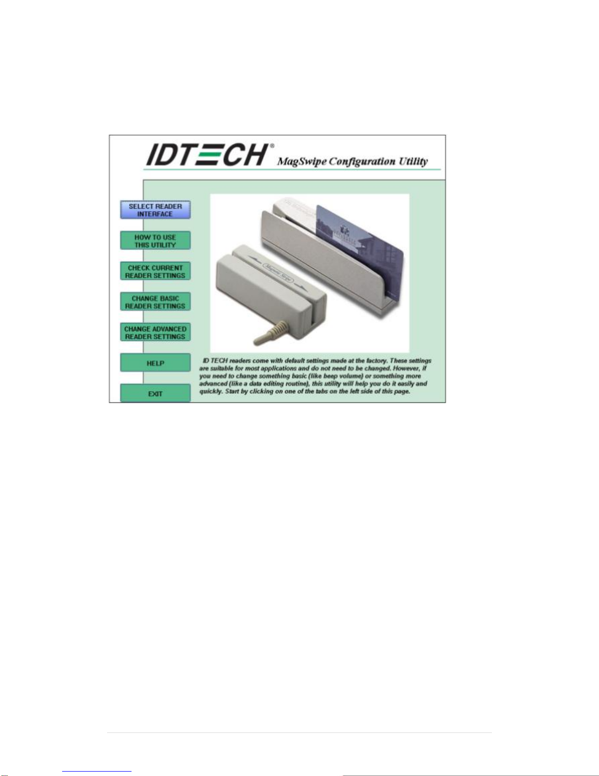
After the interface selection is made, click the Continue button. The utility attempts to
communicate with the connected reader. If successful, the Home Menu Page is displayed. The
Home Menu Page is shown below
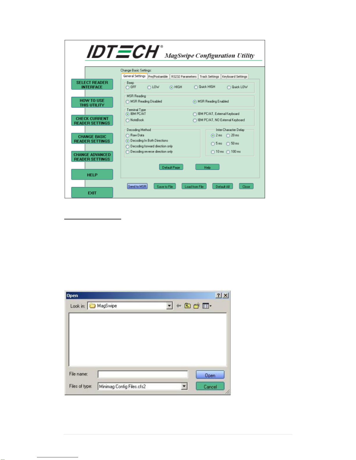
Change Basic Reader Setting
After selecting the appropriate interface for the reader, select one of the Home Menu Page
buttons to proceed with the Magnetic Stripe Reader (MSR) configuration process. The "Basic
Reader Settings" group defines the basic operating parameters and data output format of the
reader.
Page 44
Clientron PT6100 User Manual
Version: 1.0
44 | 111
Button Definitions
Send To MSR
When all the setting parameters are selected, use the "Send To MSR..." button to send
configuration data to the reader device. When the reader has received the data correctly, the
settings take effect immediately.
Load From File
The configuration data can be loaded into the configuration utility from a file that has been
previously saved. Select this command, start a "File Open" dialog, which allows selection of
the file.
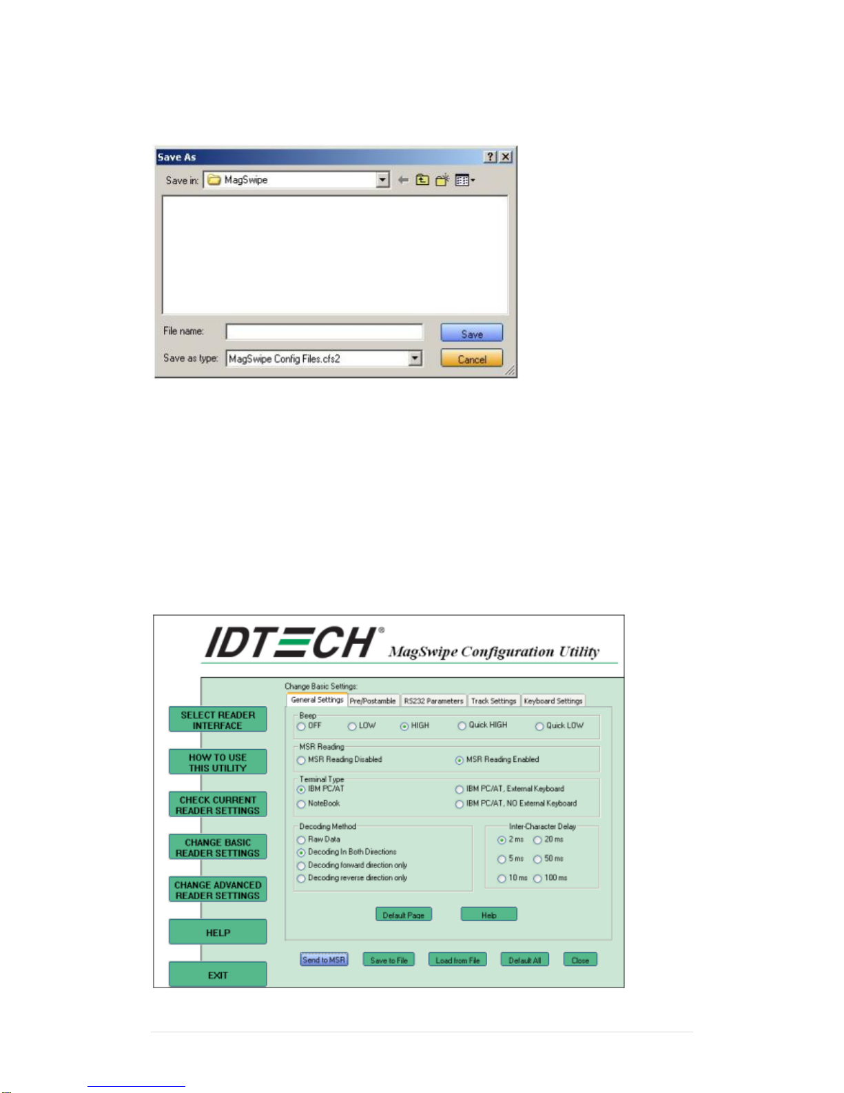
Save To File
Page 45
Clientron PT6100 User Manual
Version: 1.0
45 | 111
The configuration data can be saved as a file and being used later to configure other readers.
When saving a configuration the "File Save" dialog is opened as shown below. Input a
filename and file location.
Default All
This button sets the reader with the default configuration parameters (the default factory
settings). The settings take effect immediately. The default parameters affect all reader
configurations settings.
Close
Close this dialog and return to the Home Menu Page.
General Settings
This group of configuration settings defines the basic operating parameters of the reader.
Page 46

Clientron PT6100 User Manual
Version: 1.0
46 | 111
MSR Reading
This option will turn on or off the MSR. If MSR is disabled no data is sent out to host in any
case. The default is MSR Reading Enabled.
Decoding Method Settings
This option gives four kinds of decoding methods.
Raw Data (output in both forward and reverse directions)
Decoding in Both Directions (forward and reverse reading)
Decoding in Forward Direction only (card entering slot from LED end)
Decoding in Reverse Direction only (card entering slot from end opposite LED)
With the bi-directional operation, the user can swipe the card in both swipe directions and the
data encoded on the magnetic stripe will be output. In the single swipe direction selections, the
card can only be swiped in one specified direction to read the card. The default setting will
decoding card data with the card swiped in either the forward or the reverse direction.
"Raw Data" is an output of the decoded magnetic stripe data in hexadecimal format (no ASCII
character conversion is performed). In the Raw Data setting, the reader outputs all
track-decoded data. The MSR will represent the raw data with two ASCII characters: the first
ASCII character is for high bits of the raw data byte and the second is for the low bits. For
example, the two ASCII characters "4"and "1"represent raw data byte 41h(01000001).
Beep Volume
The Beep volume can be adjusted to four loudness levels or off. Four loudness levels are:
Quick High
Quick Low
High
Low
The default is High beep.
Terminal Type
NoteBook
IBM-PC/AT
IBM-PC/AT, External keyboard
IBM-PC/AT, No External keyboard
The firmware can be programmed to interface as a keyboard wedge to 4 different types of
terminals. The default is IBM-PC/AT.
Inter-Charater Delay :
2ms, 5ms, 10ms, 20ms, 50ms, 100ms;
This is the time period the reader will delay between sending successive characters. Some
terminals or computers (host) require an inter-character delay to simulate the effects of
keystroke delays. Choosing a longer inter-character delay causes the characters to be sent at
a slower rate. If the host system is not capable of receiving characters as fast as the reader
Page 47

Clientron PT6100 User Manual
Version: 1.0
47 | 111
can transmit, setting an appropriate inter-character delay will keep the reader from overrunning
the host input buffer. The default is 2ms.
Default Page Button
After you click the Default Button, the general settings page will change back to the default
value. Settings are not sent to MSR until the "Send to MSR" button is clicked.
Help Button
Click the help button to open the help index for this section.
Pre/Postamble
Preamble
Characters can be added to the beginning of the reader's output string of data. These can be
special characters for identifying a specific reading station, to format a message header
expected by the receiving host, or any other character string. Up to nine ASCII characters can
be defined for the Premable.
Postamble
The Postamble serves the same purpose as the Preamble, except the extra characters are
added to the end of a data string. The Postamble can be added only after a terminator
character, if specified.
Track Prefix and Suffix
For some Host applications, it may be convenient to start or end a string of reader data with a
Sentinel or terminator character.The maximum Prefix/Suffix string is six charecters and its
default is NULL(no prefix or suffix).
Track Start Sentinels
Characters can be added to the beginning of each track data string to simulate the start of the
track data. These can be special characters for identifying a specific track.
End Sentinel
The magnetic stripe End Sentinel character can be added to the end of a magnetic stripe data
string. This character simulates the end of character for track1, track2 or track3. This default is
'?'
Page 48
Clientron PT6100 User Manual
Version: 1.0
48 | 111
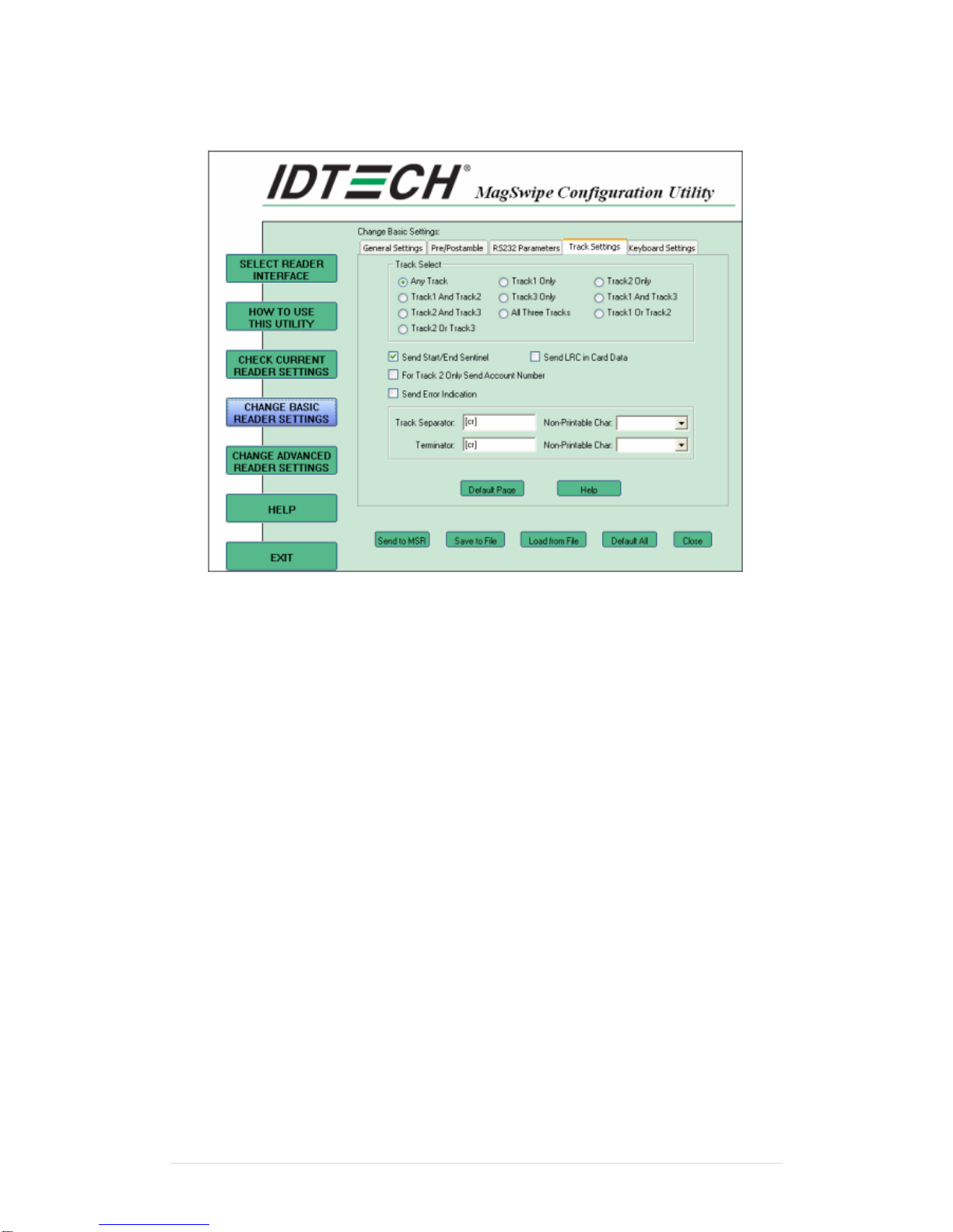
Track Settings
Track Selection
There are three tracks of info
rmation possible on a magnetic stripe. This option selects the tracks that will be decoded
(read). Note that the magnetic stripe reader must have the hardware configuration (read head
and circuits) for reading the specified tracks. If a single or dual track reader is used, the heads
must be positioned to read the tracks selected by this option. The default is Any Track.(All
tracks written on the card will be read).
Track Separator Selection
This option allows the user to select the character to be used to separate data decoded by a
multiple-track reader. The default value is CR
Send Start/End Sentinel
The reader can send the Start/End sentinel for a track, decoded without error.
Send LRC in Card Data
The reader can send the track LRC for a properly decoded track.
For Track 2 only Send Account Number
The reader can only send account Number if it is true. And if it is false, the reader sends all
Track 2 data.
Send Error Indication
This option let reader to send out [SS]E[ES] if failed to read or missing data on a selected
track.The default is off.
Page 49
Clientron PT6100 User Manual
Version: 1.0
49 | 111
The error output for track 1 is "%E?".
The error output for track 2 is ";E?".
The error output for track 3 is "+E?".
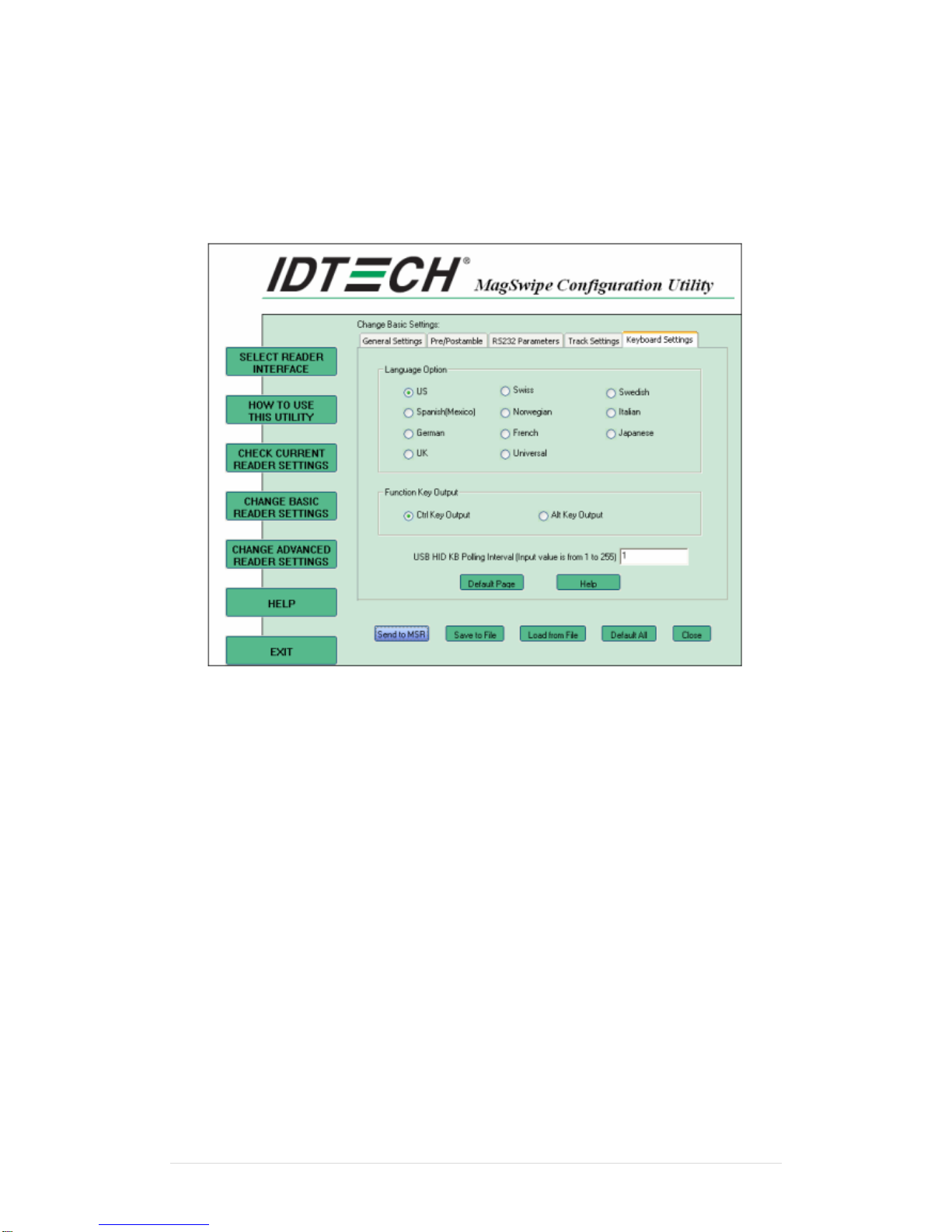
Keyboard Settings
Keyboard Settings
There are keybroad settings information on a magnetic stripe. MiniMag II will support following
foreign language keyboard and function key output for PS/2 and USB HID Keyboard Interface.
Language Option
This option allows the user to select the keyboard language of US, Swiss, Swedish, Norwegian,
Italian, Spanish(Mexico), German, French, Japanese, UK and Universal. Universal language
sends out all the data as a series of ALT keyped sequence.
Function Key Output
The function key output be used to support the special key to delay card data output.
USB HID KB Polling Interview
The user can input the number between 1 to 255 for the delay of output.
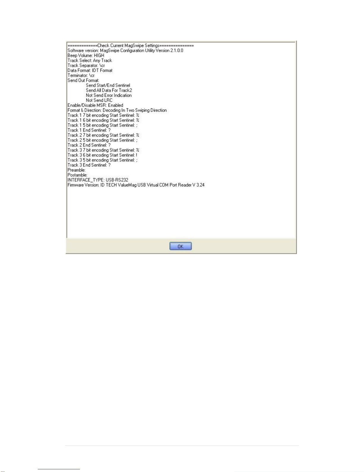
Check Current Reader Setting
After you connect the device, the current reader configuration can be displayed by selecting
this button. The configuration data of the connected reader will be displayed like in the
example:
Page 50
Clientron PT6100 User Manual
Version: 1.0
50 | 111
Page 51
Clientron PT6100 User Manual
Version: 1.0
51 | 111
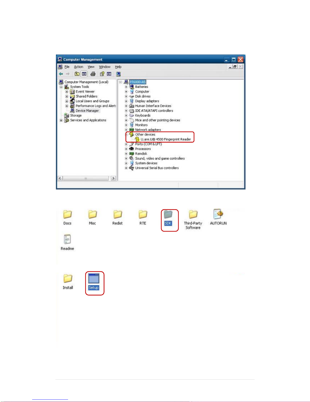
6-3 Fingerprint Reader
1. Check Fingerprint reader be detected by “Device manager “
2. Select SDK folder.
3. Run Setup.exe.
Page 52
Clientron PT6100 User Manual
Version: 1.0
52 | 111
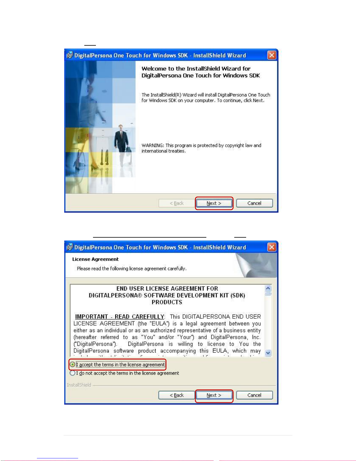
4.Click “Next”.
5. Select “ I accept the terms in the license agreement” and click “Next”.
Page 53
Clientron PT6100 User Manual
Version: 1.0
53 | 111
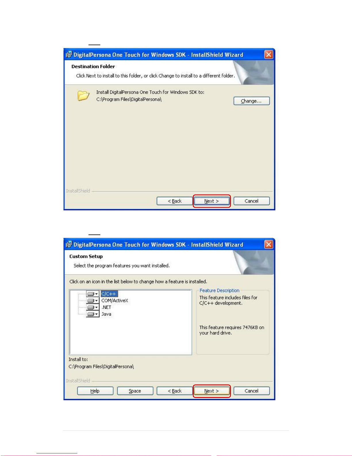
6. Click “Next”.
7. Click “Next”.
Page 54
Clientron PT6100 User Manual
Version: 1.0
54 | 111
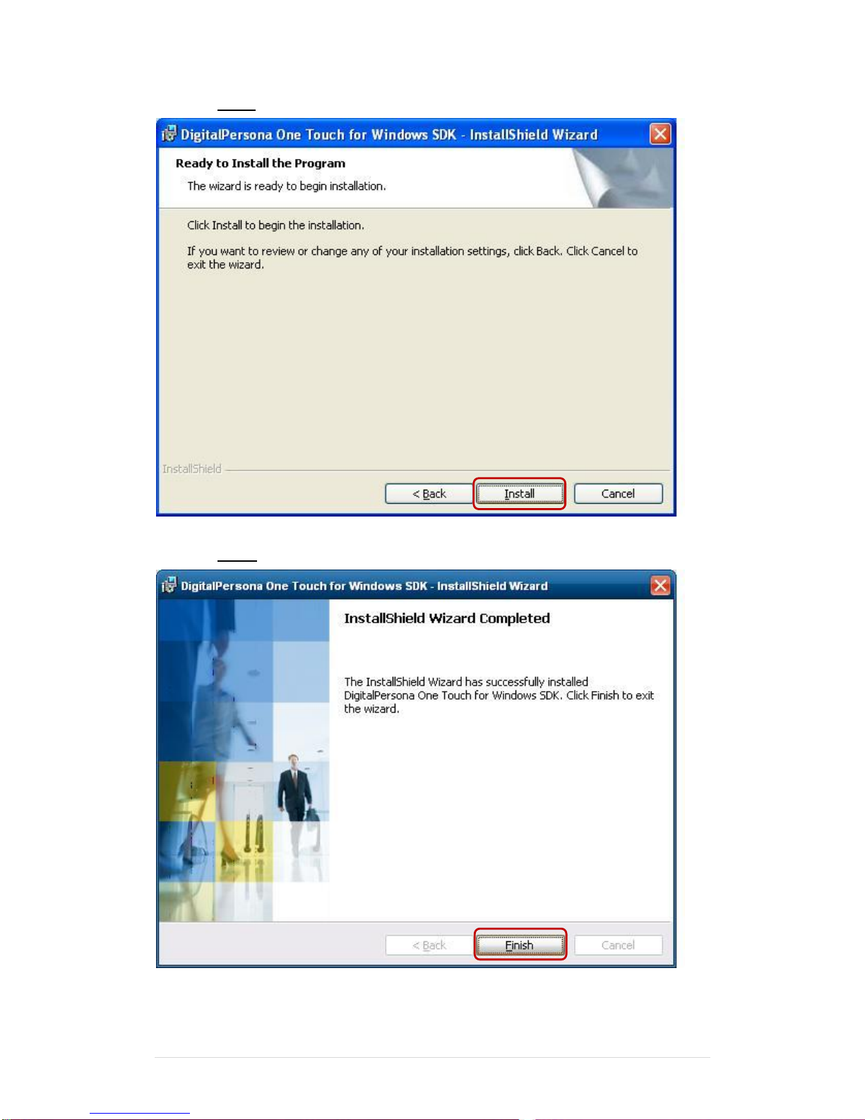
8. Click “Install”.
9. Click “Finish”.
Page 55
Clientron PT6100 User Manual
Version: 1.0
55 | 111
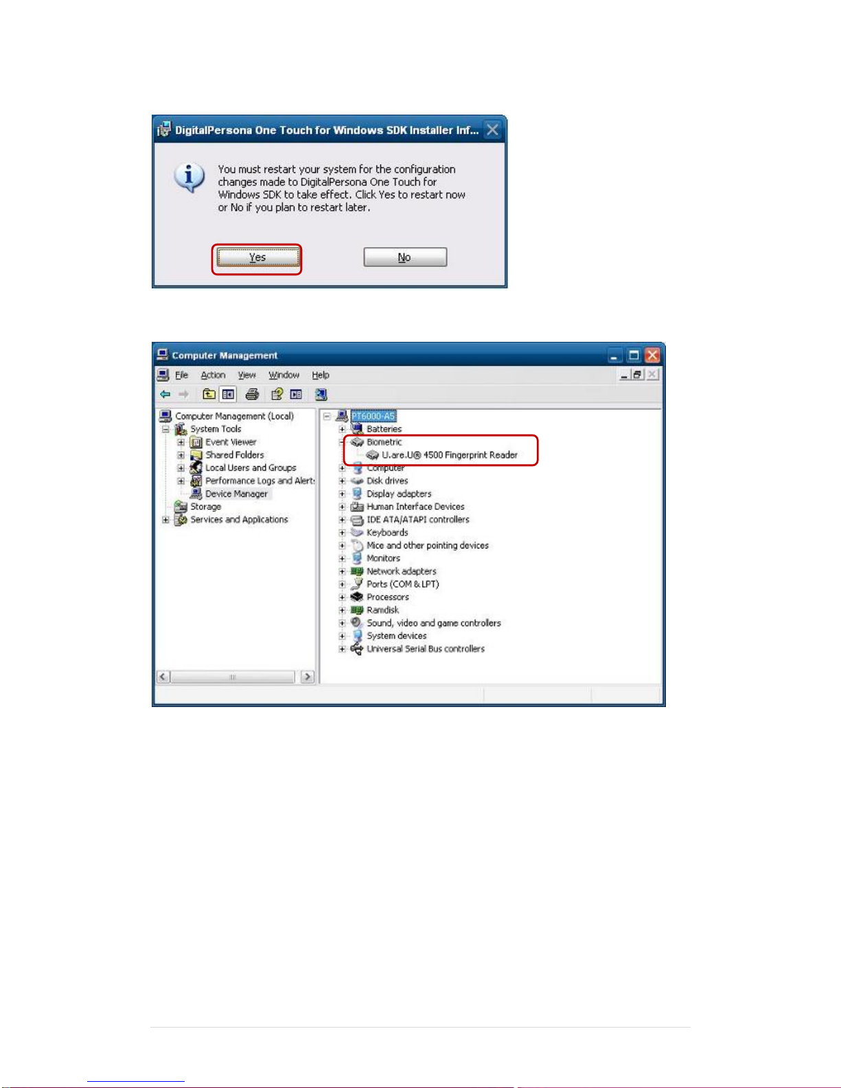
10. Restart systems.
11. Check Fingerprint reader in Device Manager.
Page 56
Clientron PT6100 User Manual
Version: 1.0
56 | 111
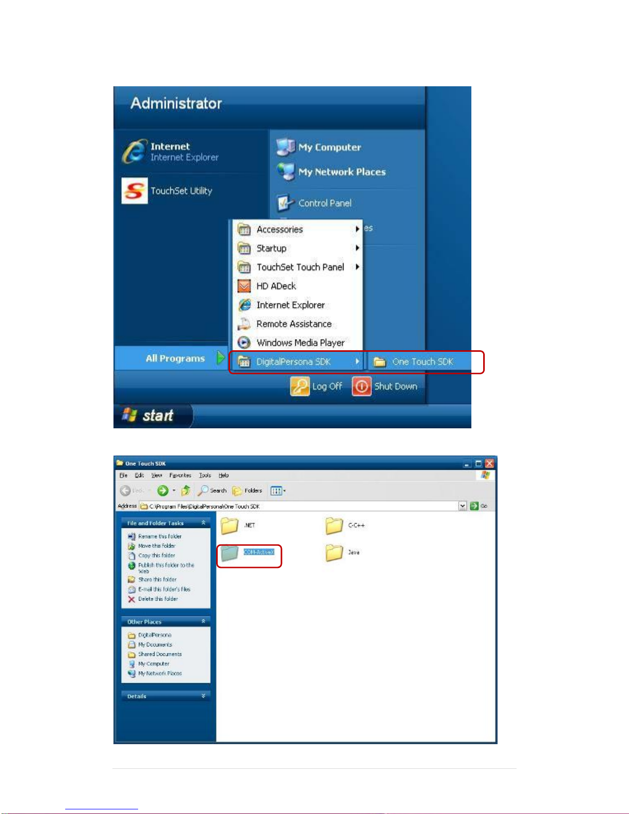
12. Launch Fingerprint reader from start menu
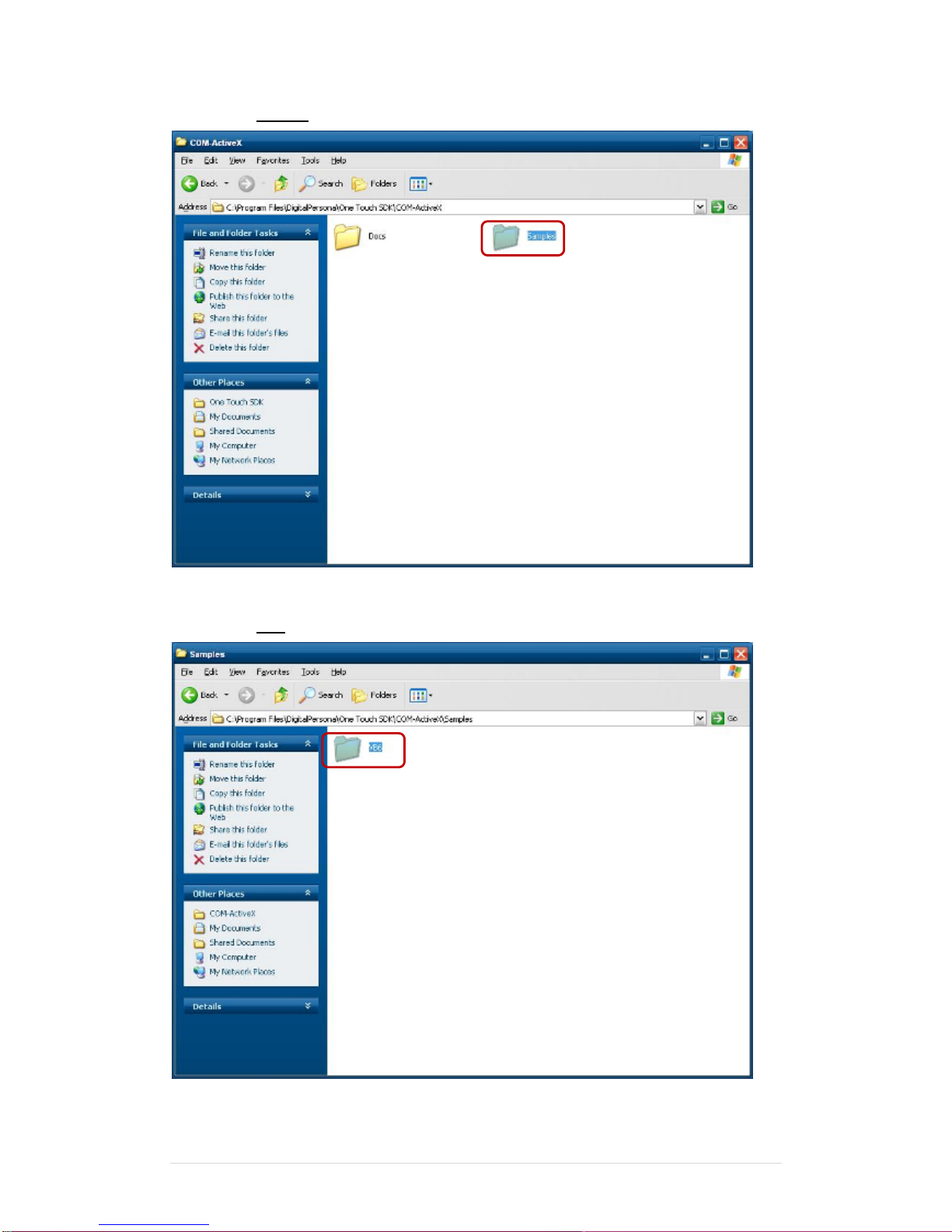
13. Select “COM-ActiveX”
Page 57
Clientron PT6100 User Manual
Version: 1.0
57 | 111
14. Select “Sample”
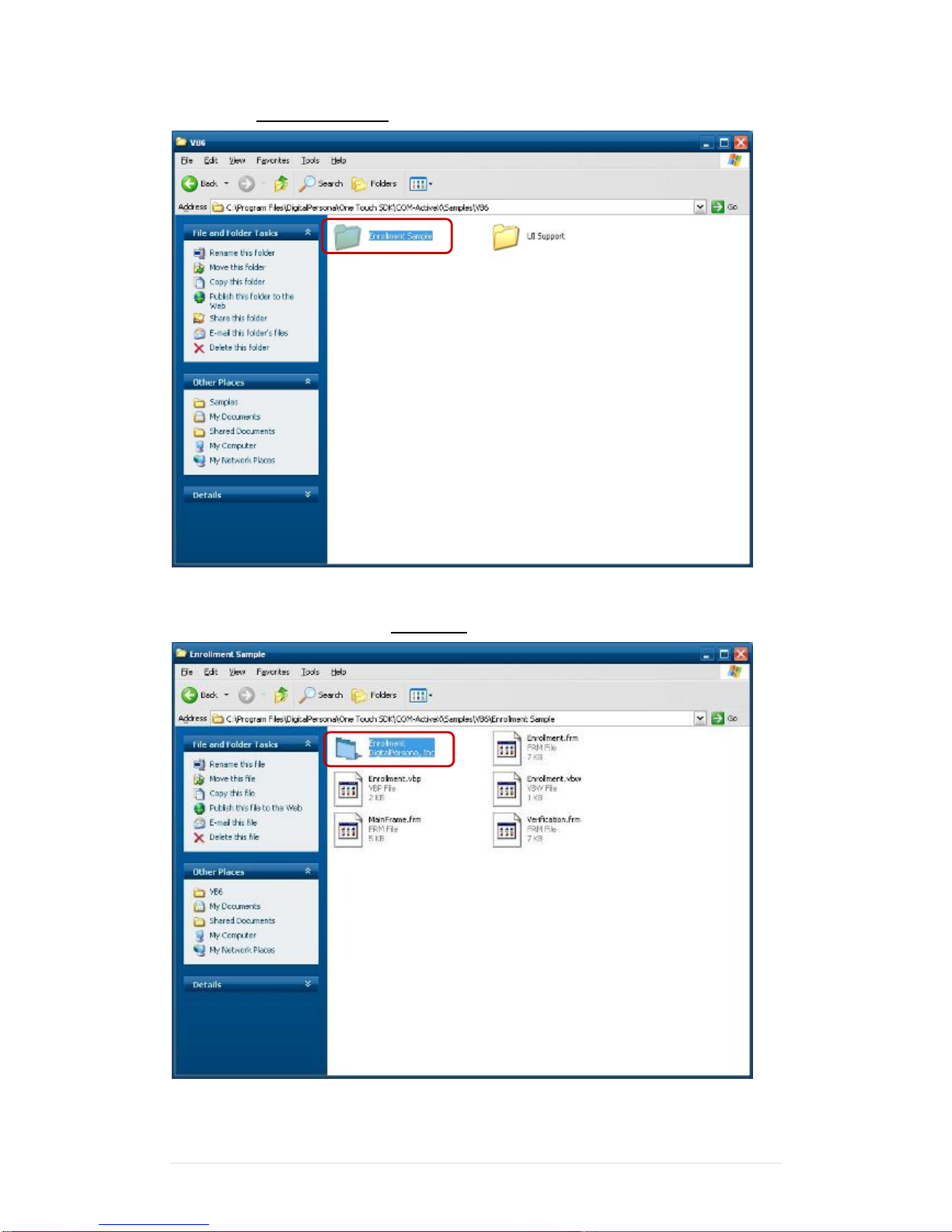
15. Select ”VB6’.
Page 58
Clientron PT6100 User Manual
Version: 1.0
58 | 111
16. Select “Enrollment Sample”.
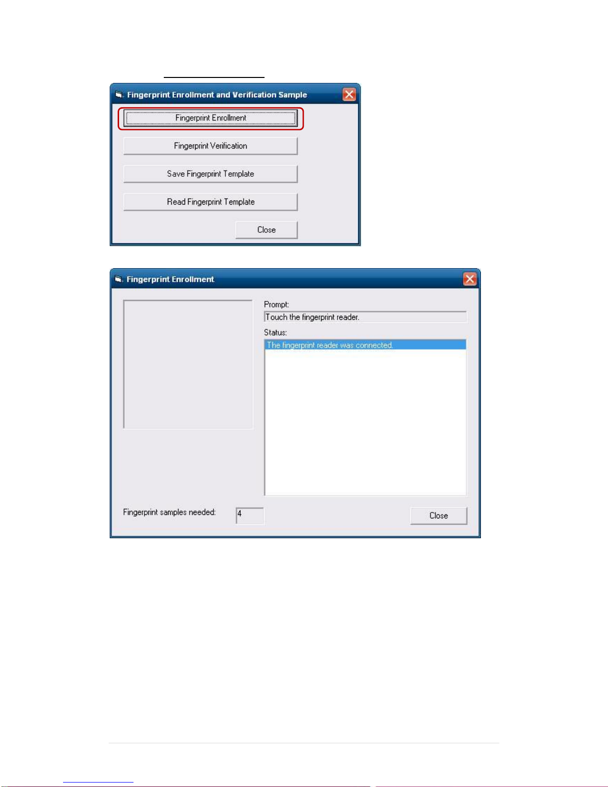
17. Enroll the fingerprint by the “Enrollment“
Page 59
Clientron PT6100 User Manual
Version: 1.0
59 | 111
18. Select “Fingerprint Enrollment”
Page 60
Clientron PT6100 User Manual
Version: 1.0
60 | 111
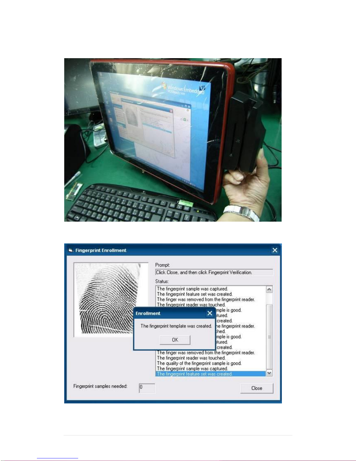
19. Put your finger on fingerprint reader and follow the direction to enroller your fingerprint, it
need scan your fingerprint 4 times
20. After enroller finish it will popup a dialog box
Page 61
Clientron PT6100 User Manual
Version: 1.0
61 | 111
6-4 RFID
1. Install
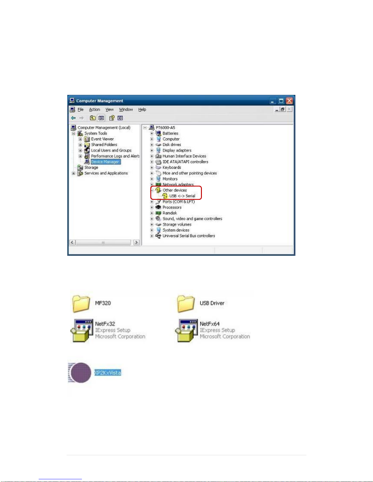
1.1 Check the Device Manager to verify the status of RFID reader.
Computer Management -> Device Manager -> Other devices (The device will show a
question mark if the installation is not done properly.)
1.2 Install RFID driver,file name:XP2KxVista.exe
2-1 Path:\USB Driver\ XP2KxVista.exe
Page 62
Clientron PT6100 User Manual
Version: 1.0
62 | 111
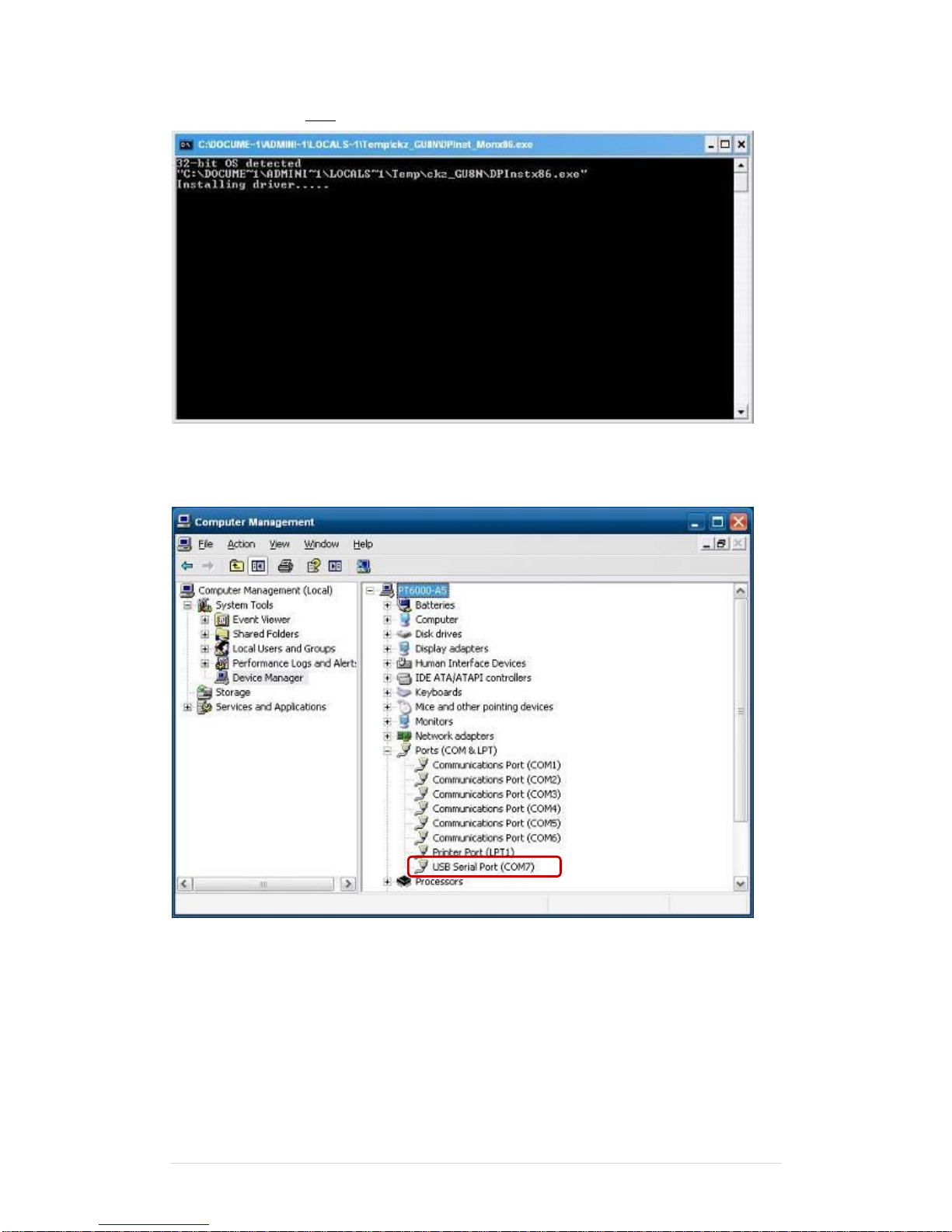
1.2.1 After clicking Next, A pop up console window appears as below.
1.2.2 Check the Device Manager to verify the status of RFID reader.
Computer Management -> Device Manager -> Ports (COM & LPT)
Page 63
Clientron PT6100 User Manual
Version: 1.0
63 | 111
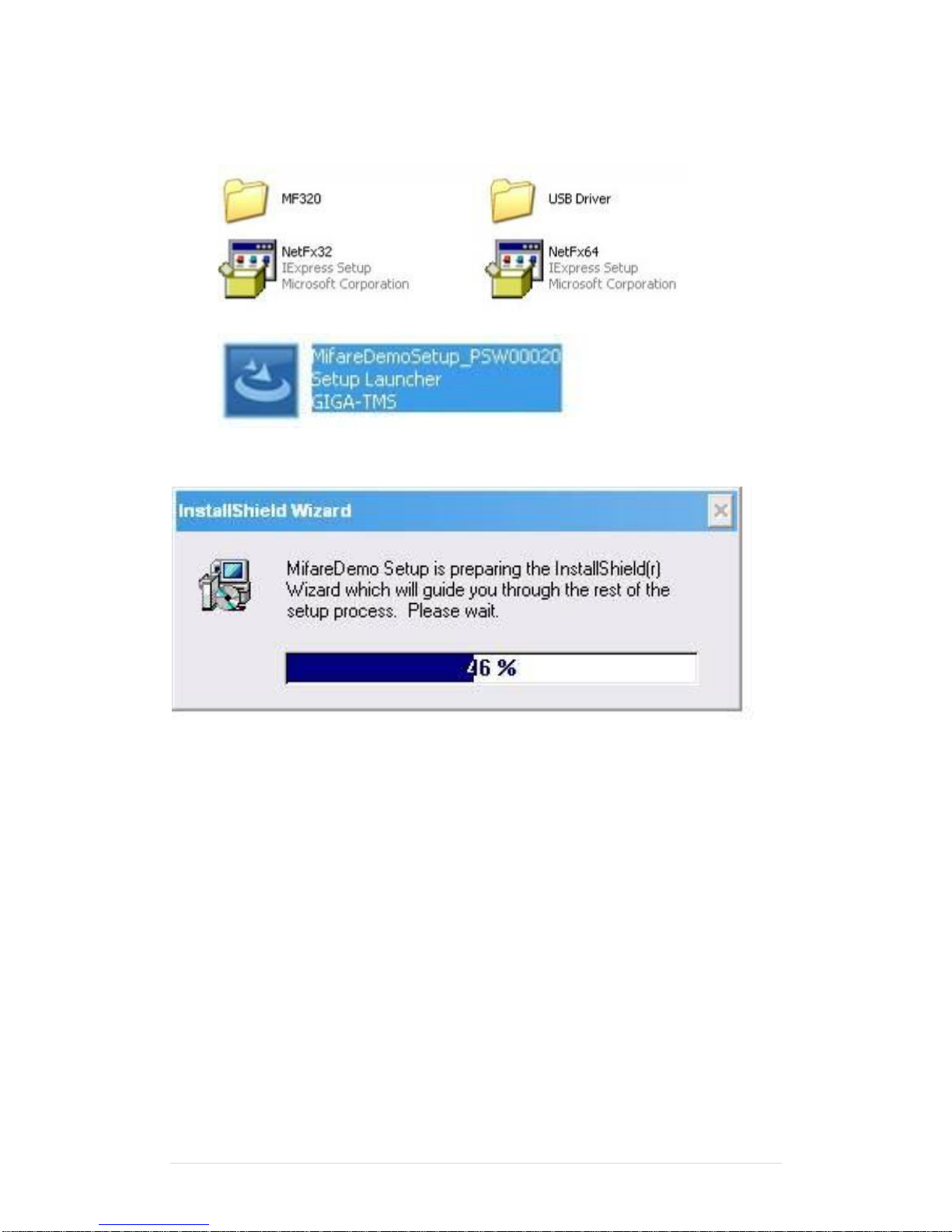
1.3 install RFID utility
MifareDemoSetup_PSW00020.exe
3-1 Path:\MF320\MifareDemoSetup_PSW00020.exe
1.3.1 InstallShield Wizard will be activated.
Page 64
Clientron PT6100 User Manual
Version: 1.0
64 | 111
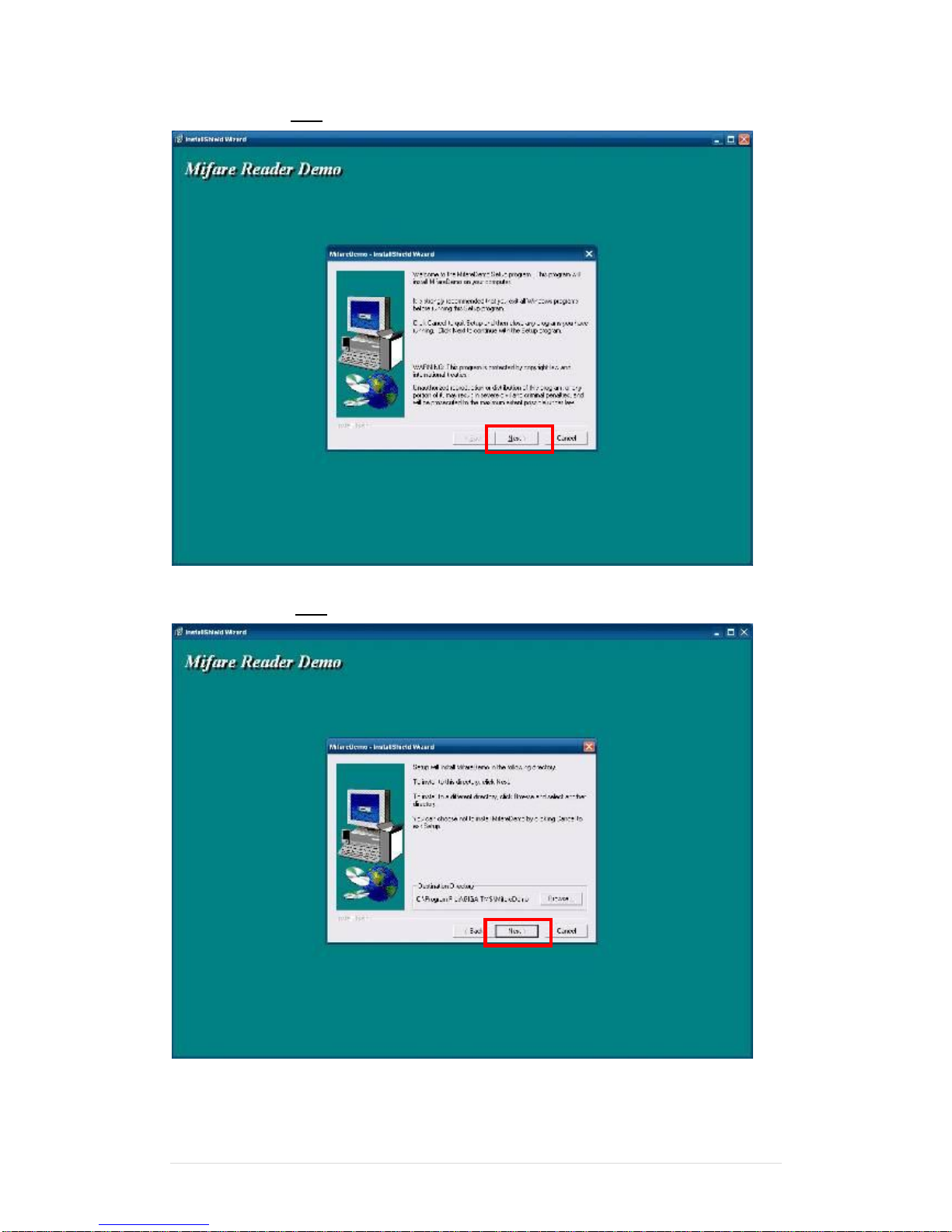
1.3.2 Click “Next”.
1.3.3 Click “Next”.
Page 65
Clientron PT6100 User Manual
Version: 1.0
65 | 111
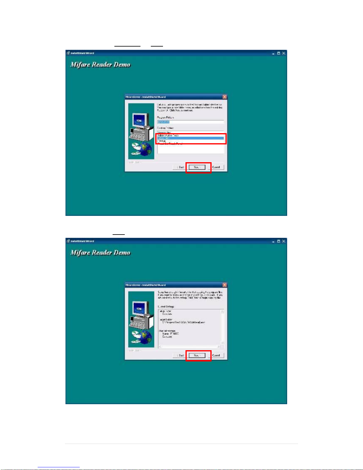
1.3.4 Click “Giga-TMS” & “Next”.
1.3.5 Click “Next”.
Page 66
Clientron PT6100 User Manual
Version: 1.0
66 | 111
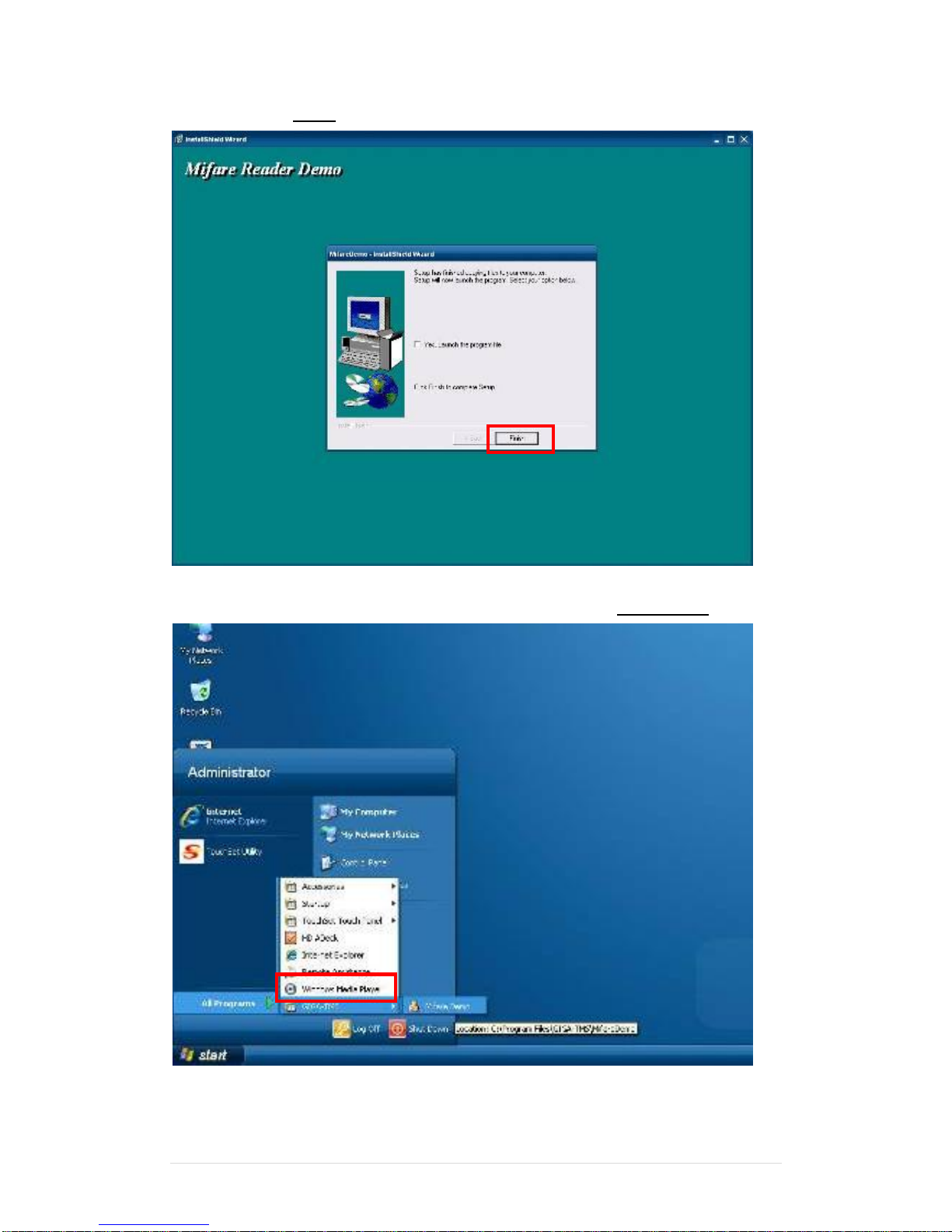
1.3.6 Click “Finish”
2. Run RFID demo program. Start -> All Programs -> GIGA-TMS -> Mifare Demo
Page 67
Clientron PT6100 User Manual
Version: 1.0
67 | 111
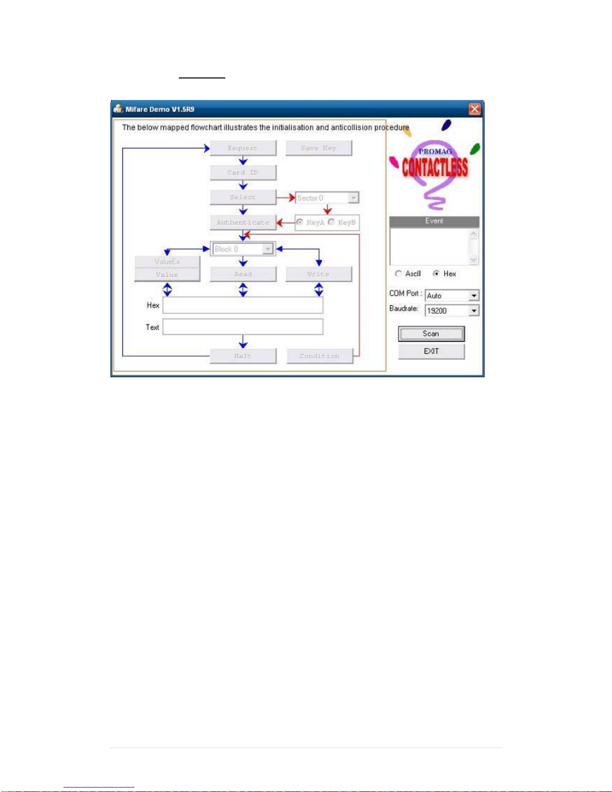
2.1 Run “Auto Scan” Demo AP will detect the RFID reader automatically.
Or select the RFID COM port
Page 68
Clientron PT6100 User Manual
Version: 1.0
68 | 111
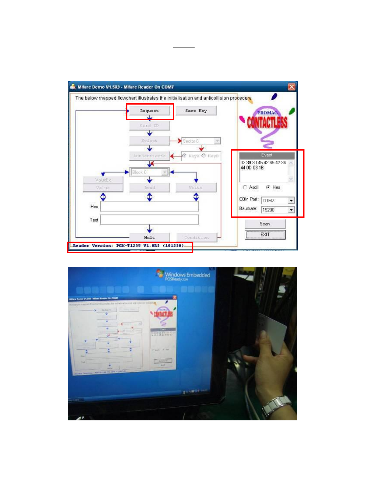
2.2 After finishing the AutoScan, Request box will be ready for the click and Reader
Version will show on the position as marked. (Reader Version: PGM-T1235 V1.0R3
(101230) Place Mifare Card to the RFID reader area. Event Dialog window gets the
data from the Mifare Card.
Place the RFID card on the RFID reader.
Page 69
Clientron PT6100 User Manual
Version: 1.0
69 | 111
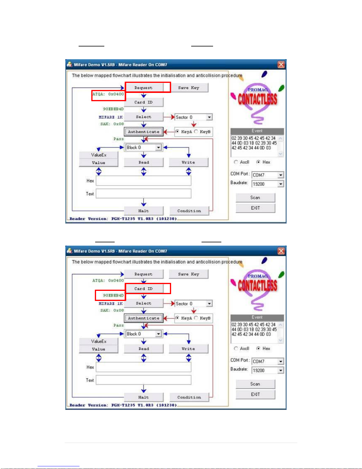
2.3 Card type will be recognized when you click “Request”.
(Your Mifare card should be placed on the RFID reader area.)
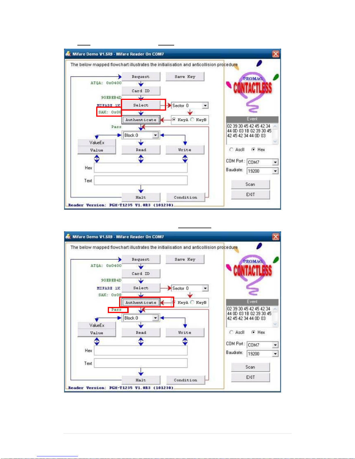
2.4 Card ID will be recognized when you click “Card ID”.
Page 70
Clientron PT6100 User Manual
Version: 1.0
70 | 111
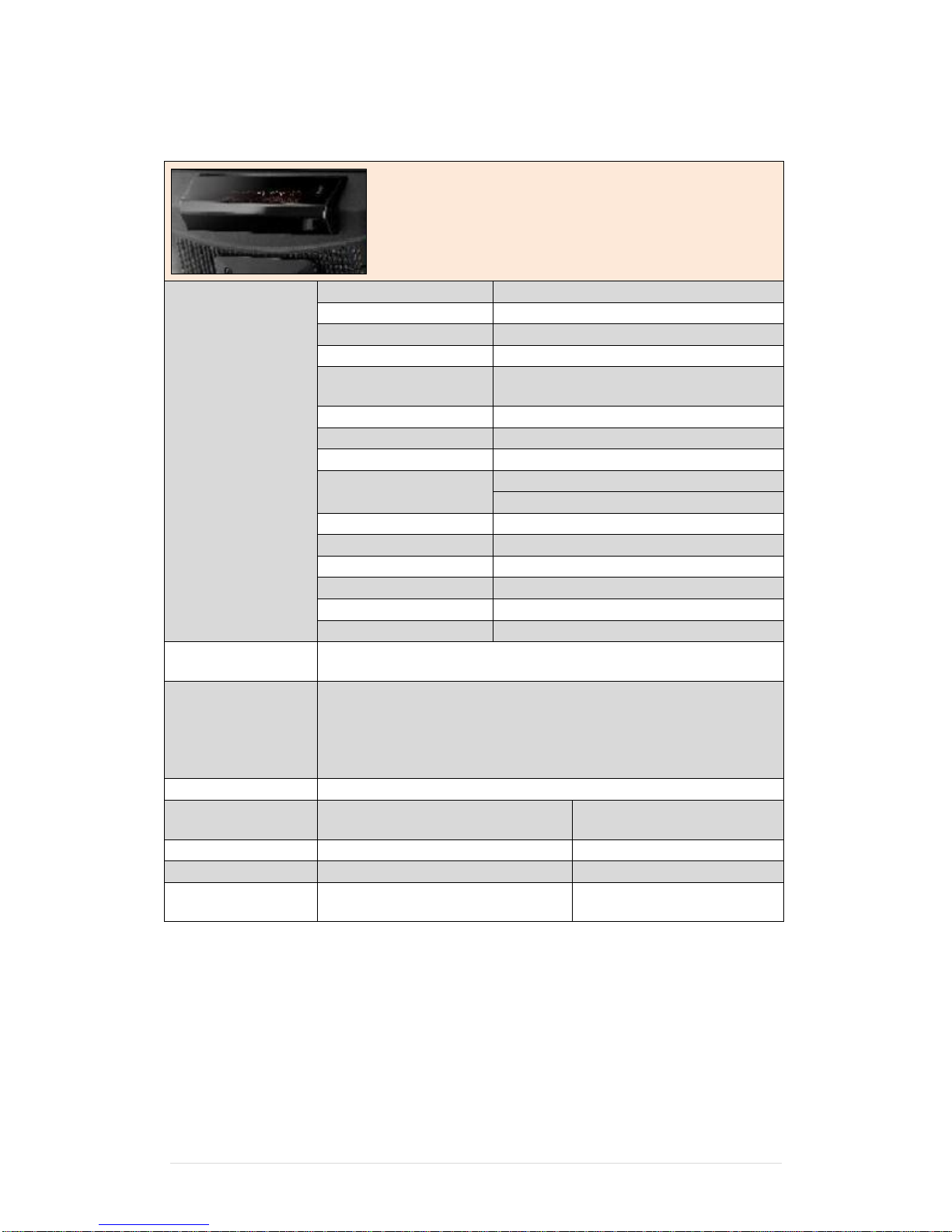
2.5 SAK will be read when you click “Select”.
2.6 The result will show when you click “Authenticate”.
Page 71
Clientron PT6100 User Manual
Version: 1.0
71 | 111
6-5 Internal VFD
Specification
General
Display Method
Vacuum Fluorescent Display(blue-Green)
Number of Characters
40 (20 Columns X 2 Lines)
Brightness
500 ~ 1000 cd/m2
Character Font
5X7 Doc Matrix
Character Type
95 Alphanumeric, 32 International
Characters
Character Size
6.75(H) X 3.75(W)mm
Doc Size (X x Y)
0.55 x 0.75 mm
Download Characters
9 Characters
Height
4.70” (120mm) with Stand-alone Base
9.80” (250mm) with Base and 1 Extension
Panel Dimension
75(H) x 170(W) x 50(D) mm
Pole Dimension
Per Support Length: 130 mm
Base Dimension
33(H) x 159.8(W) x 100(D) mm
Viewing Angle
Max. 90o
Horizontal Rotation
Max. 355 o
Weight
Approx. 980 Grams
Commands Mode
LD220, EPSON, AEDEX, UTC/S, UTC/P, ADM788, DSP800,
CD5220, EMAX, LOGIC CONTROL, Ultimate
Language Support
US English, Int’l English, Bosnia, Croatian, Czech, Danish, Dutch,
Estonian, Faroese, Finnish, Flemish, French, Fr Canadian, German,
Greek, Hebrew, Hungarian, Icelandic, Indonesian, Irish, Italian,
Katakana, Latvian, Lithuanian, Norwegian, Polish, Portuguese,
Romanian, Russian, Slovene, Slovak, Spanish, Swedish
Interface
RS-232(Serial)
Connection
Baud Rate
Direct Connection 9600 or
19,200 bps
Reliability
MTBF
30,000 Hours
Power
Consumption
5 VDC
Safety
EMC Standards
Safety Standards
FCC, CE
Page 72
Clientron PT6100 User Manual
Version: 1.0
72 | 111
Page 73
Clientron PT6100 User Manual
Version: 1.0
73 | 111
Page 74
Clientron PT6100 User Manual
Version: 1.0
74 | 111
Page 75
Clientron PT6100 User Manual
Version: 1.0
75 | 111
6-6 Configuration Utility of i-Button Reader
Notice: For the i-Button Reader device, there are two installation positions with two
different I-button readers from different vendor.
Please select correct configuration utility for installation
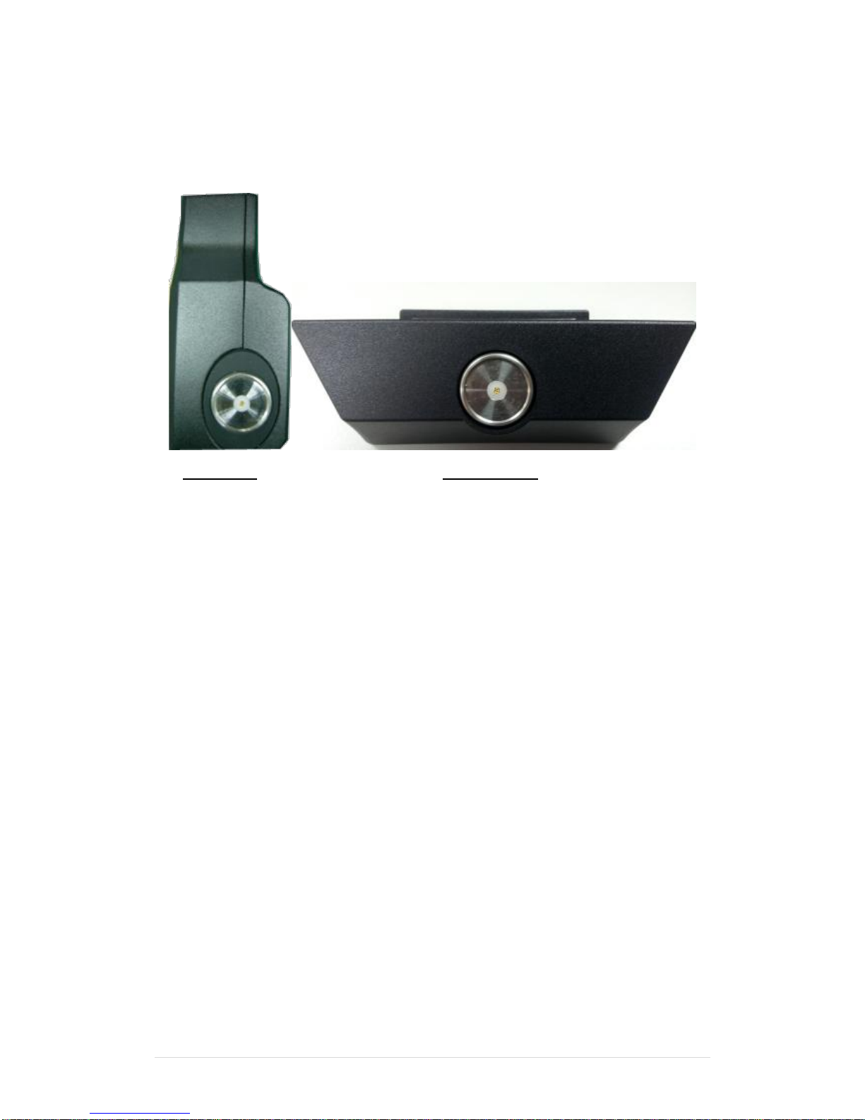
3 in 1 MSR Bottom Case
1. i-Button Reader positioned at side MSR
The i-Button Reader Configuration Utility is used to set up the output format of HID MSR
Installation
Below steps guide you how to install the Utility program.
Insert the setup CD
Run the HIDMSR-20 Utility.exe setup file that is located in the Software folder of CD.
Follow the wizard to complete the installation.
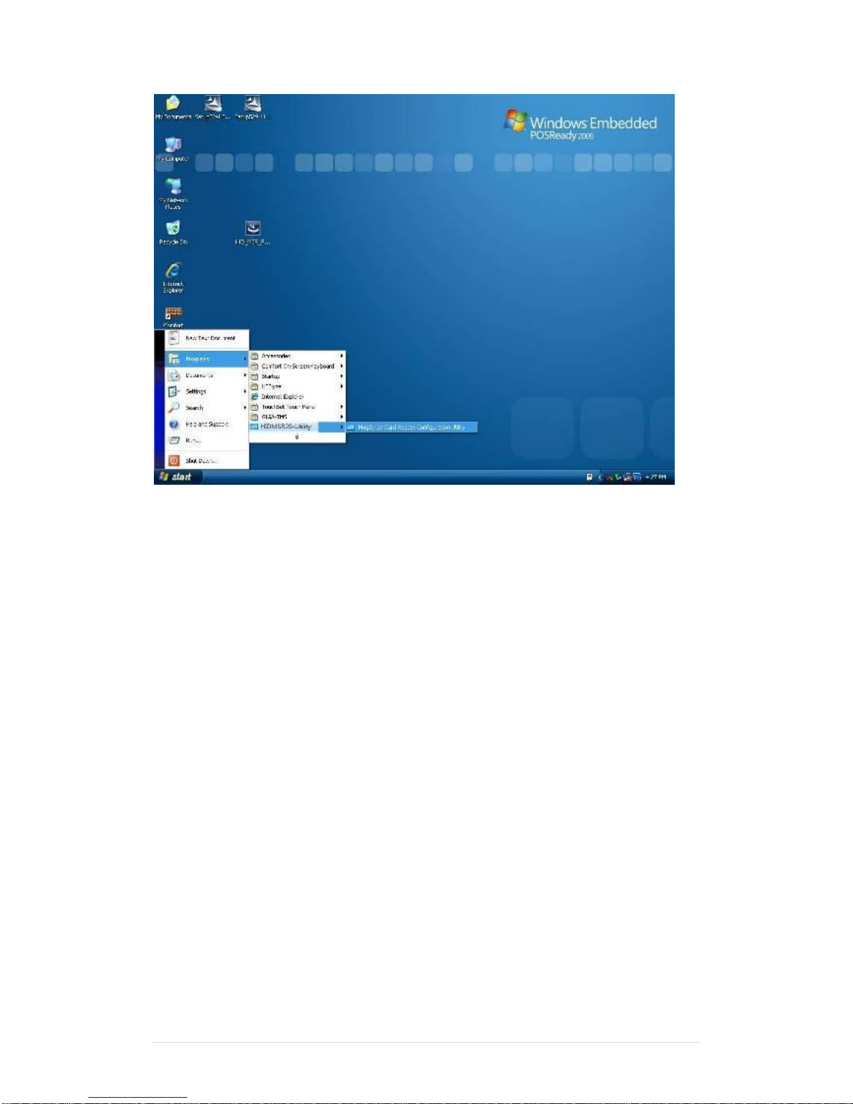
Launching Program
Below steps guide you how to load the Utility program.
From Start/Programs, click HIDMSR-20 Utility folder
Click MagStripe Card Reader Configuration Utility to launch the program.
Page 76
Clientron PT6100 User Manual
Version: 1.0
76 | 111
Page 77
Clientron PT6100 User Manual
Version: 1.0
77 | 111
The utility program will detect the connected reader. If detected, all the input text boxes
will be enabled.
If the reader has not been connected to PC yet, please connect the reader and then click
Refresh to get connected.
Configuration
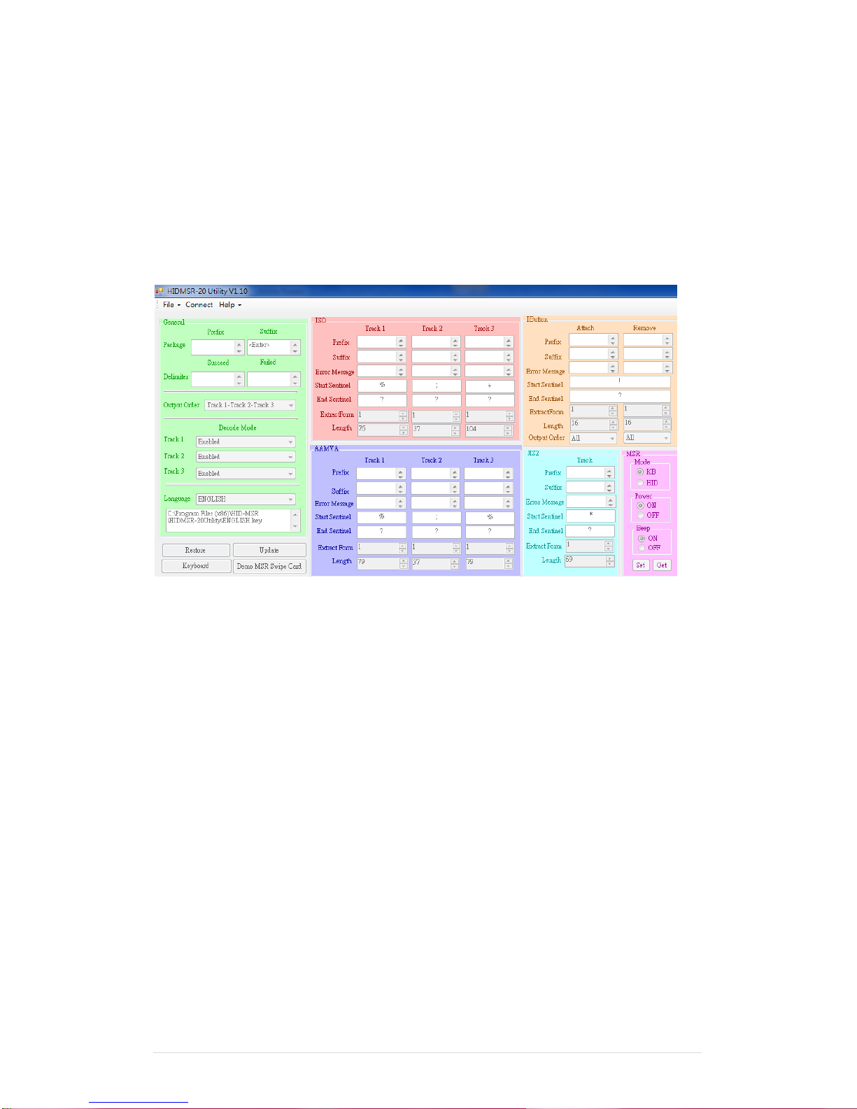
Below is the main window of i-Button Utility program.
For the settings, there are:
Prefix/Suffix: Defines the data string which you would like to append in front or end of
the i-Button key string.
Error Message: Indicates error message when i-Button key read fail.
Message: Indicates message when i-Button key read correctly
SS/ES : Define Start and End sentinel byte for the i-Button ID string
Length : i-Button ID length request from 0~16
Output order : 5 formats could be select at Attach /Remove i-Button ID
0. 0-All
1- CRC.ID
2- ID, FC
3- ID
4-Disabled
Update Settings
Once complete the settings, click Update to update the settings to connected HID MSR
Page 78

Clientron PT6100 User Manual
Version: 1.0
78 | 111
reader.
Save Settings
To save the settings to a file, click Save; specify the file name and location to be saved.
Open Settings
To load pre-saved settings, click Open, specify the settings file, and then click OK to load into
program.
Restore MSR Reader Settings
To load restore settings of connected MSR reader, click Restore ES2: End sentinel for track.
Page 79
Clientron PT6100 User Manual
Version: 1.0
79 | 111
2. I-Button Reader positioned at bottom case
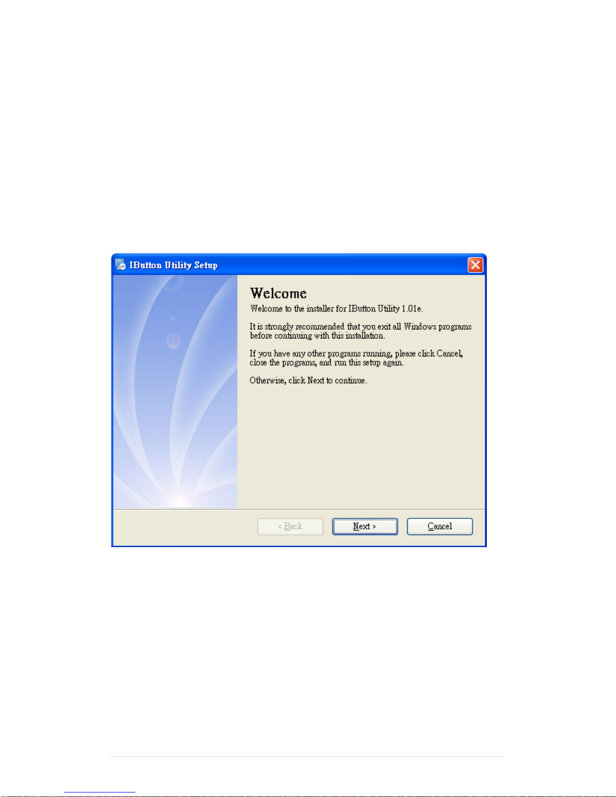
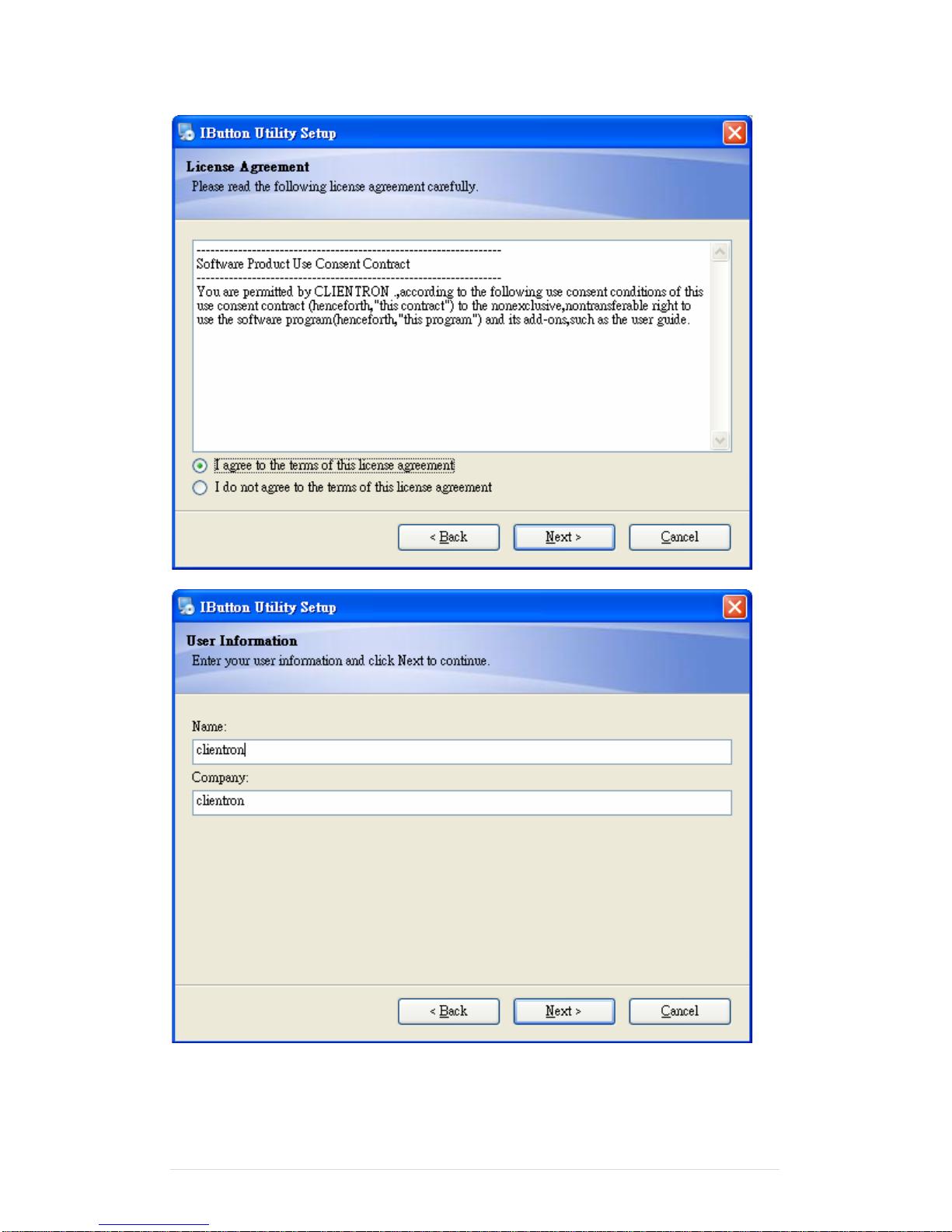
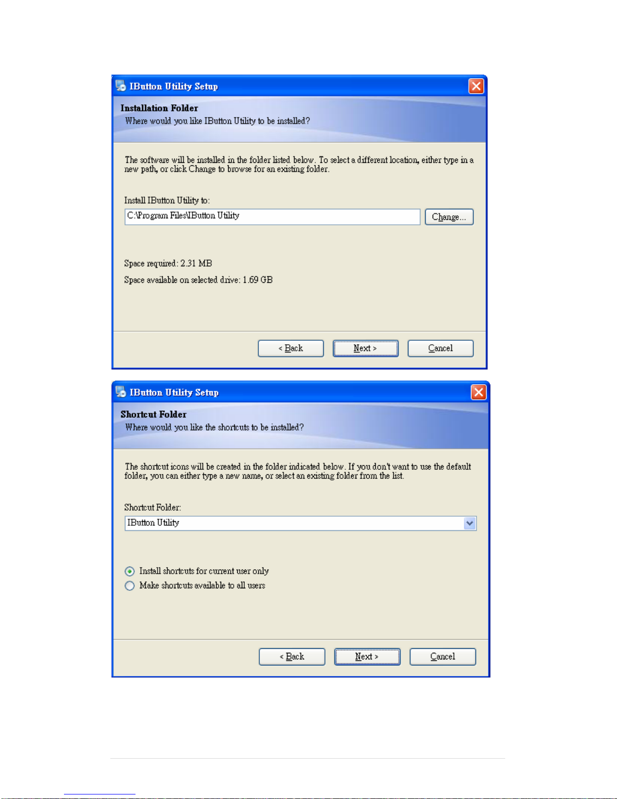
Installation
Below steps guide you how to install the Utility program.
Insert the setup CD
Run the Clientron I Button Utility.exe setup file that is located in the Software folder of
CD
Follow the wizard to complete the installation.
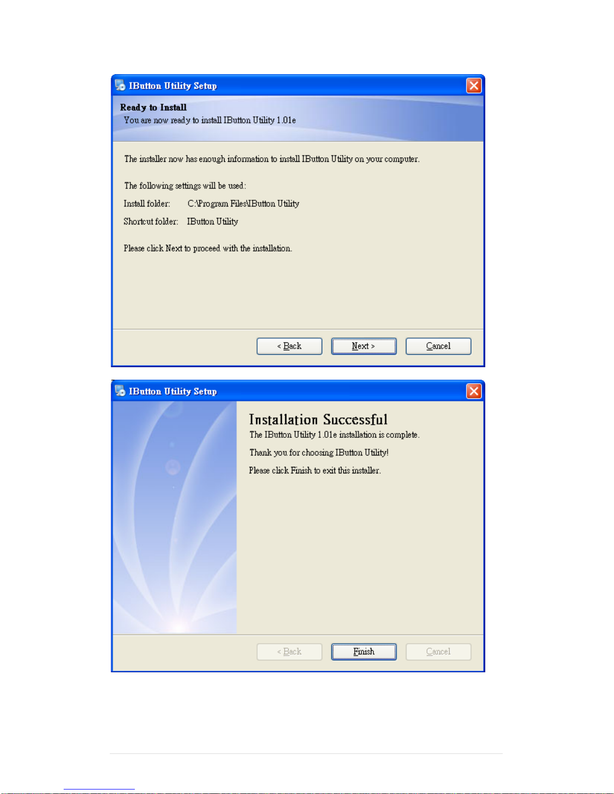
1. Setup IButton _V1.0.exe software
Page 80
Clientron PT6100 User Manual
Version: 1.0
80 | 111
Page 81
Clientron PT6100 User Manual
Version: 1.0
81 | 111
Page 82
Clientron PT6100 User Manual
Version: 1.0
82 | 111
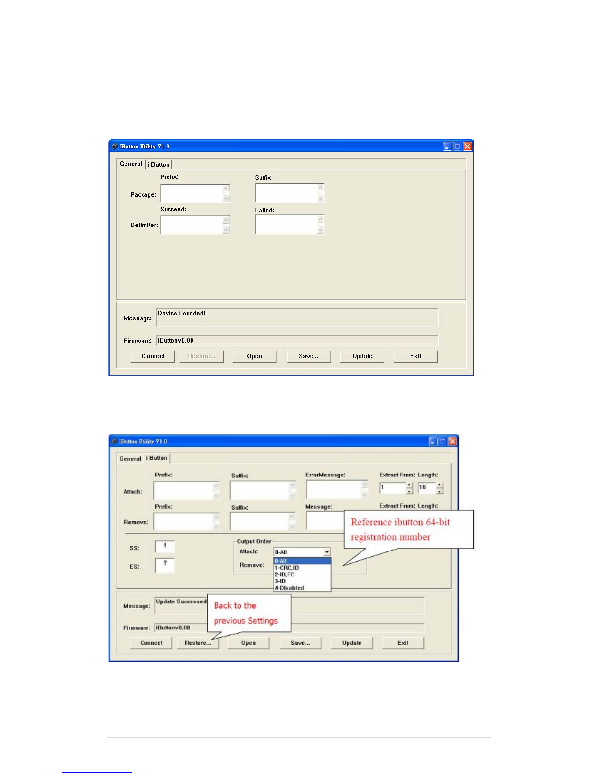
2. To execute “IButton_V1.0.exe” for setup communication between software and
IButton module.
Page 83
Clientron PT6100 User Manual
Version: 1.0
83 | 111
● The utility program will detect the connected reader. If detected, all the input
text boxes will be enabled.
● If the reader has not been connected to PC yet, please connect the reader and
then click Refresh to get connected.
Configuration
Below is the main window of i-Button Utility program.
Page 84
Clientron PT6100 User Manual
Version: 1.0
84 | 111
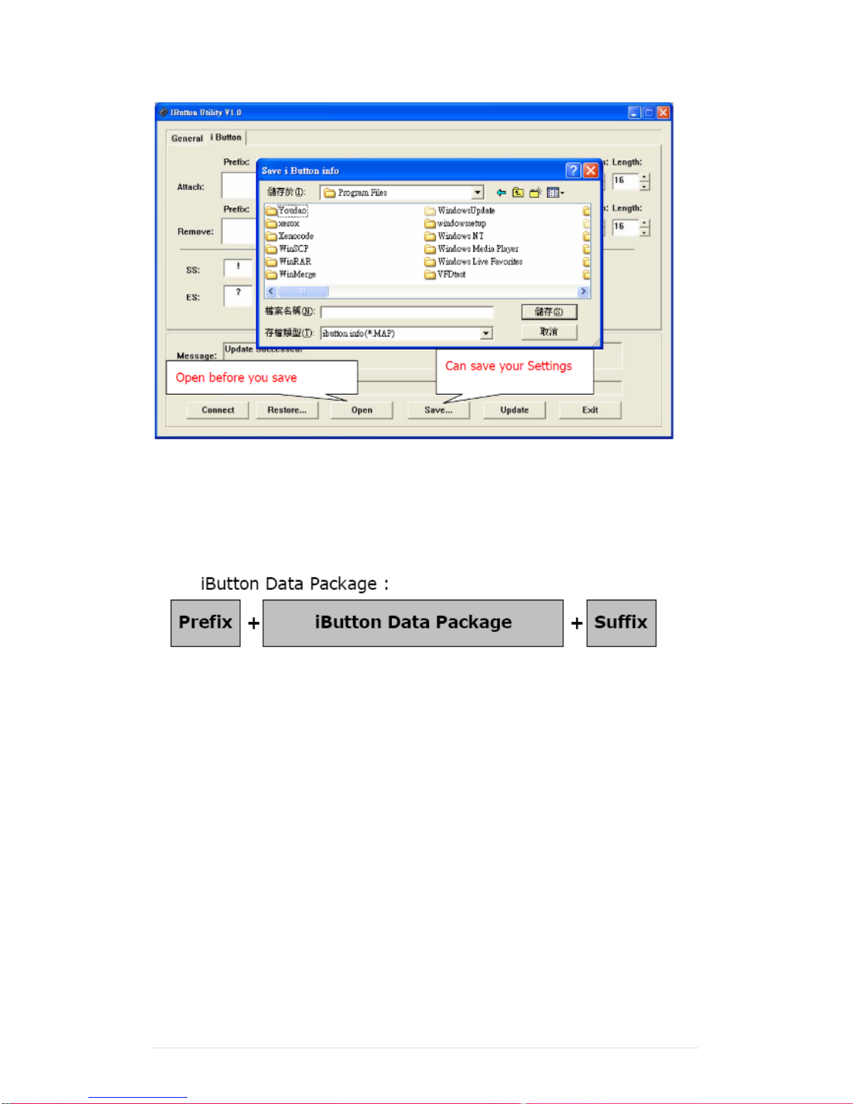
For the settings, there are:
● Prefix/Suffix: Defines the data string which you would like to append in front or
end of the i-Button key string.
● Error Message: Indicates error message when i-Button key read fail.
● Message: Indicates message when i-Button key read correctly
● SS/ES : Define Start and End sentinel byte for the i-Button ID string
iButton data formate:
SS + iButton 64- Bit Registration Number + ES
● Length : i-Button ID length request from 0~16
● Output order : 4 formats could be select at Attach /Remove i-Button ID
iButton 64- Bit Registration Number:
8-Bit CRC + 48-Bit ID + 8-Bit FC
Page 85
Clientron PT6100 User Manual
Version: 1.0
85 | 111
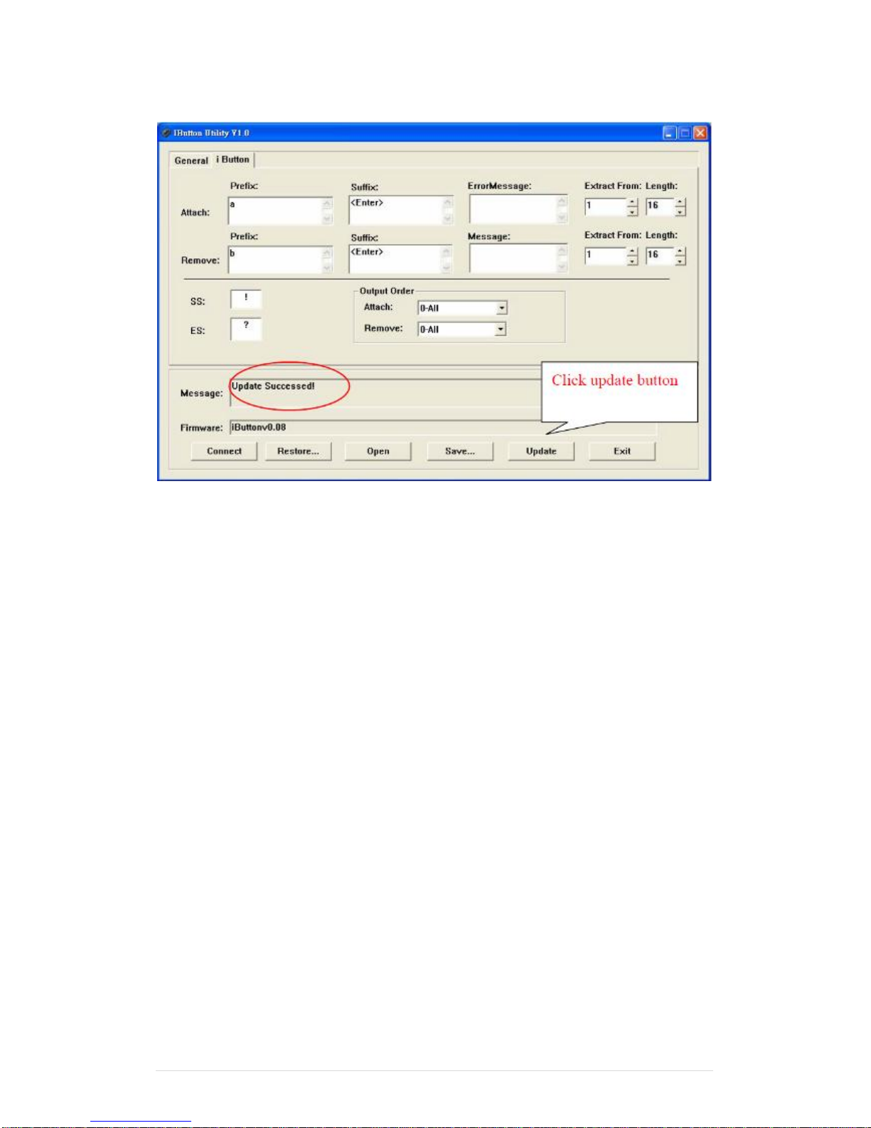
DEMO SETUP&OUTPUT
OUTPUT DATA :
a!ab00000003bdfa01?
b!ab00000003bdfa01?
Page 86
Clientron PT6100 User Manual
Version: 1.0
86 | 111
6-7 Installation and Testing of Smart Card Reader
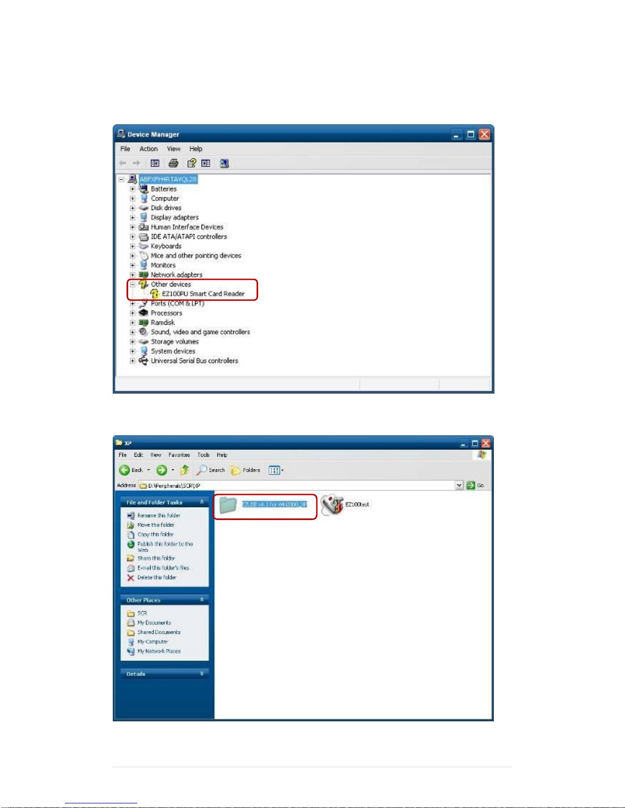
1. Check smart card reader be detected by “Device manager”.
2. Install the SCR driver.
Page 87
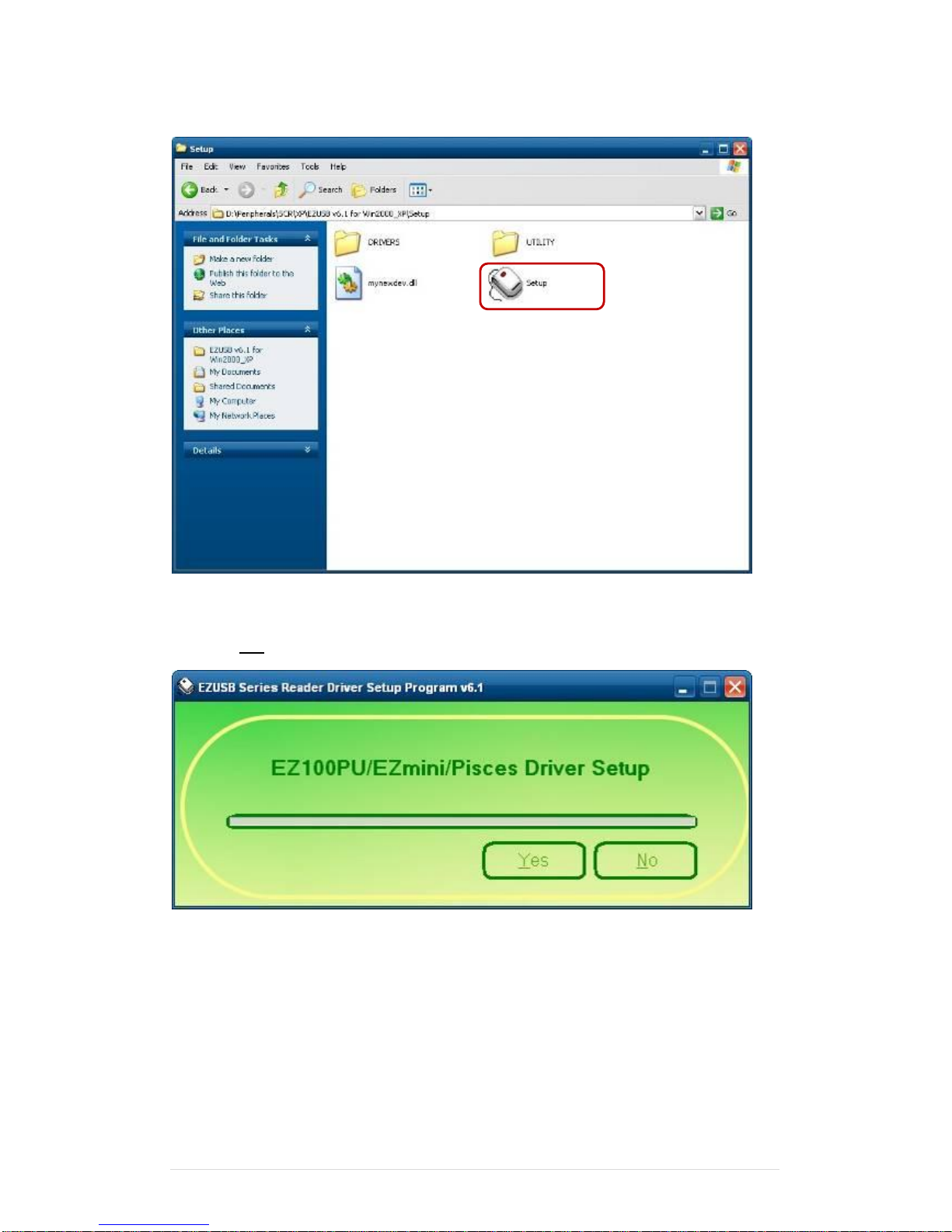
Clientron PT6100 User Manual
Version: 1.0
87 | 111
3. Run Setup.exe.
4. Click “Yes”.
Page 88
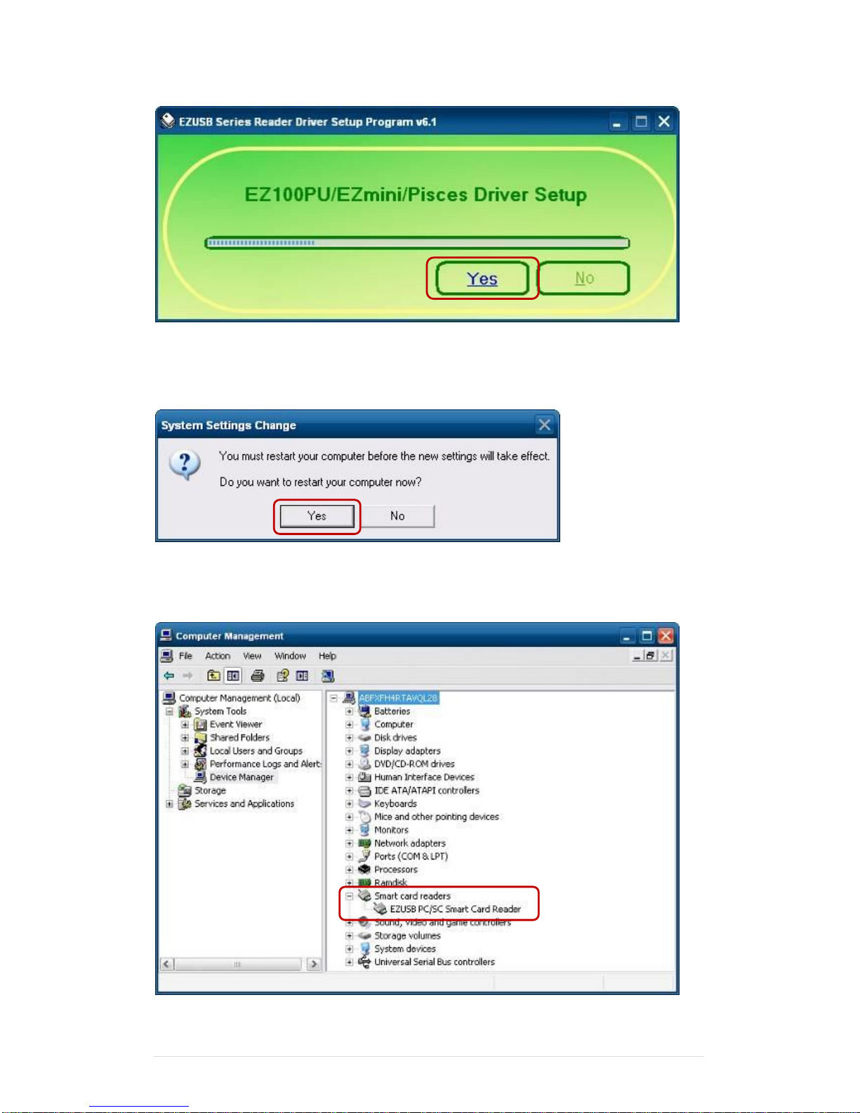
Clientron PT6100 User Manual
Version: 1.0
88 | 111
5. Restart systems.
6. Check SCR reader in Device Manager.
Page 89
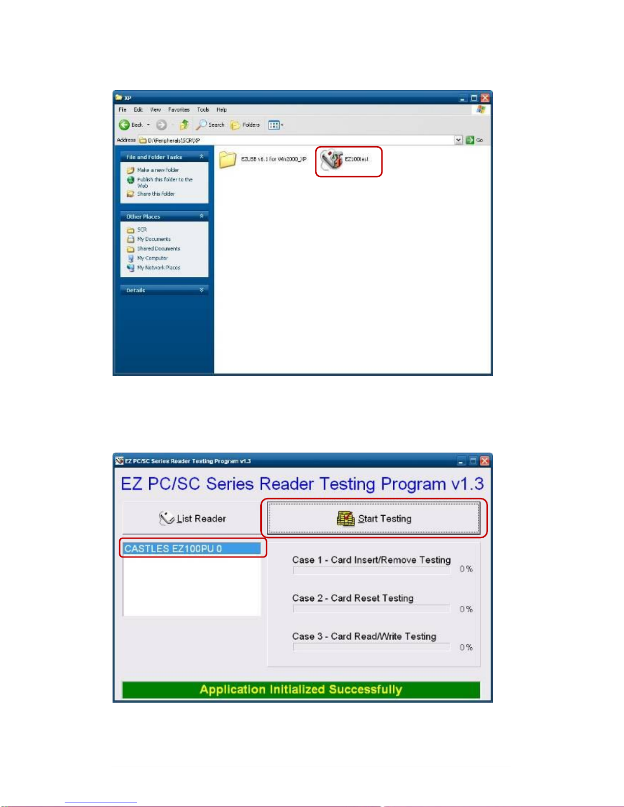
Clientron PT6100 User Manual
Version: 1.0
89 | 111
7. Run the testing program – EZ100test.
8. Conferm that SCR can be detected by the testing program, then run the program - the
Start Testing.
Page 90
Clientron PT6100 User Manual
Version: 1.0
90 | 111
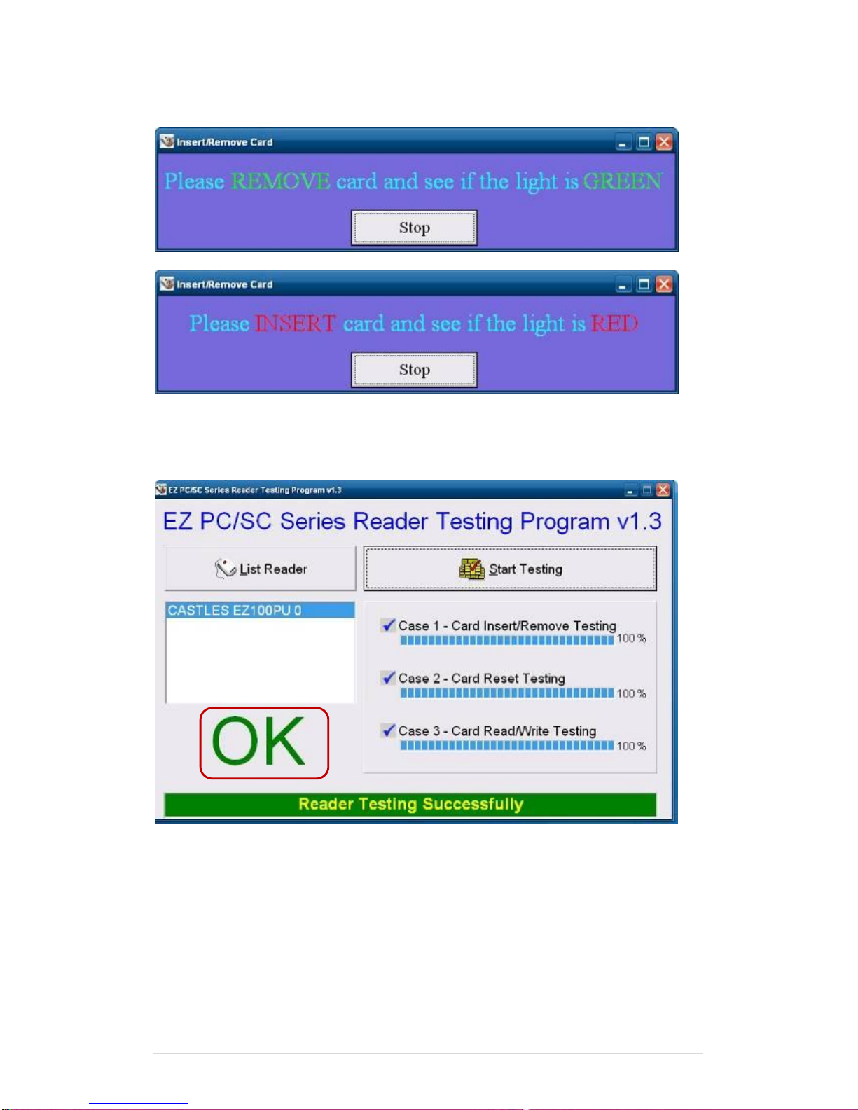
9. Follow dialog boxes displayed to remove and insert card.
10. After finishing the testing, the dialog box will show “oK”.
Page 91
Clientron PT6100 User Manual
Version: 1.0
91 | 111
6-8 WiFi
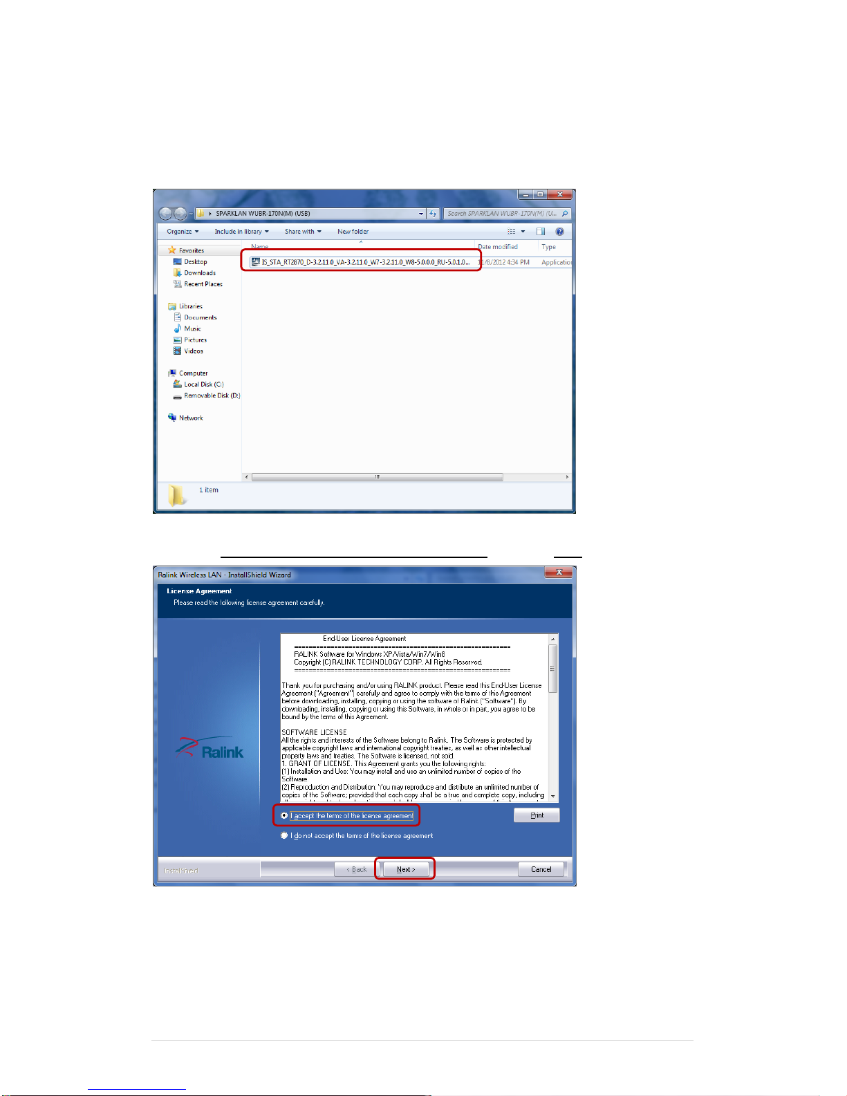
1. Install the WiFi driver.
2. Select “I accept the terms of the license agreement” and click “Next”
Page 92
Clientron PT6100 User Manual
Version: 1.0
92 | 111
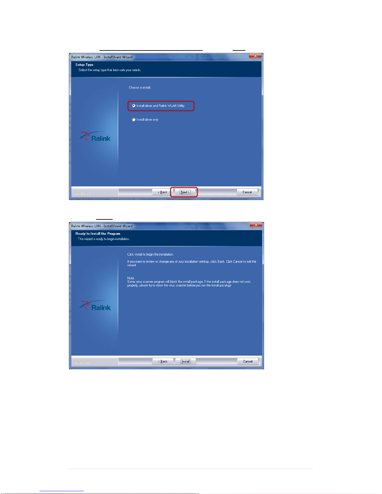
3. Select “Install driver and Ralink WLAN Utility” and click “Next”
4. Click “Install”
Page 93
Clientron PT6100 User Manual
Version: 1.0
93 | 111
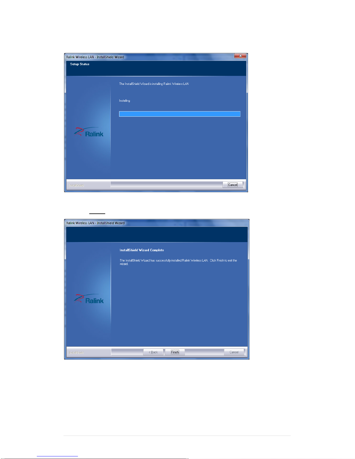
5. Starting install
6. Click “Finish”
Page 94
Clientron PT6100 User Manual
Version: 1.0
94 | 111
6-9 Pole type VFD VD1220
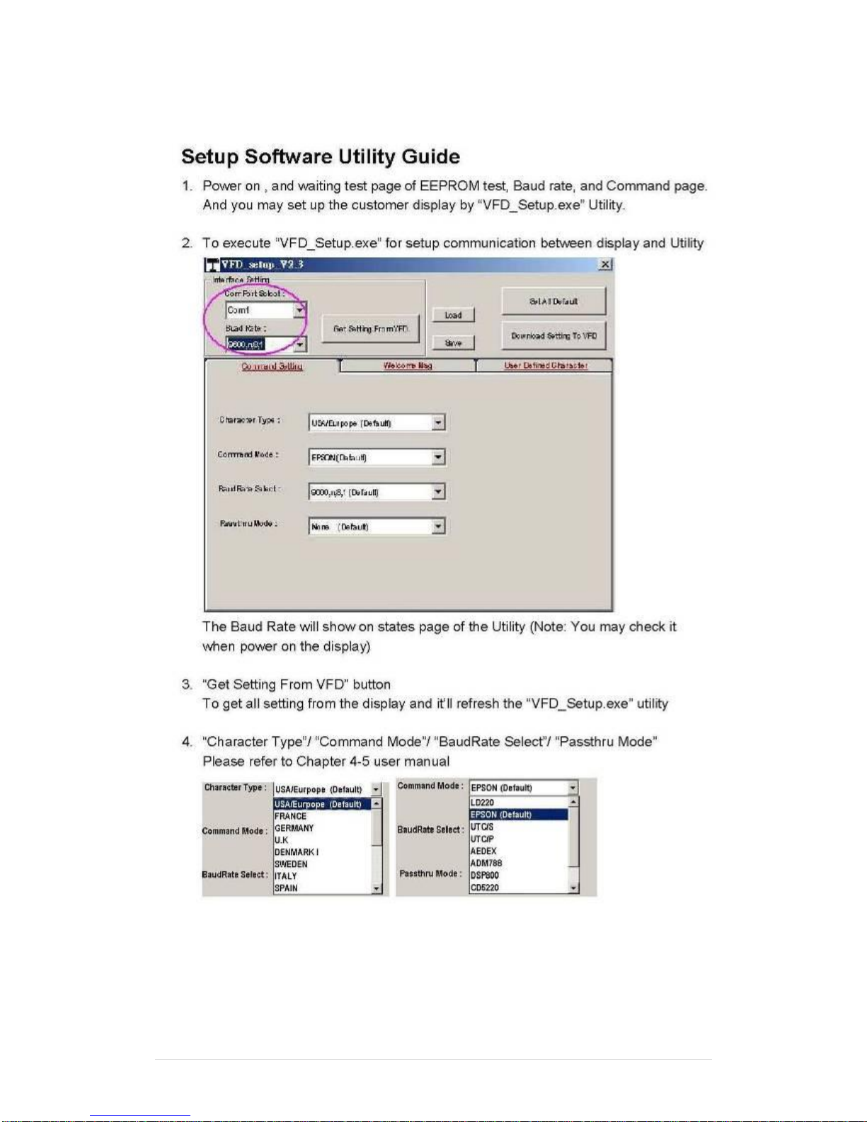
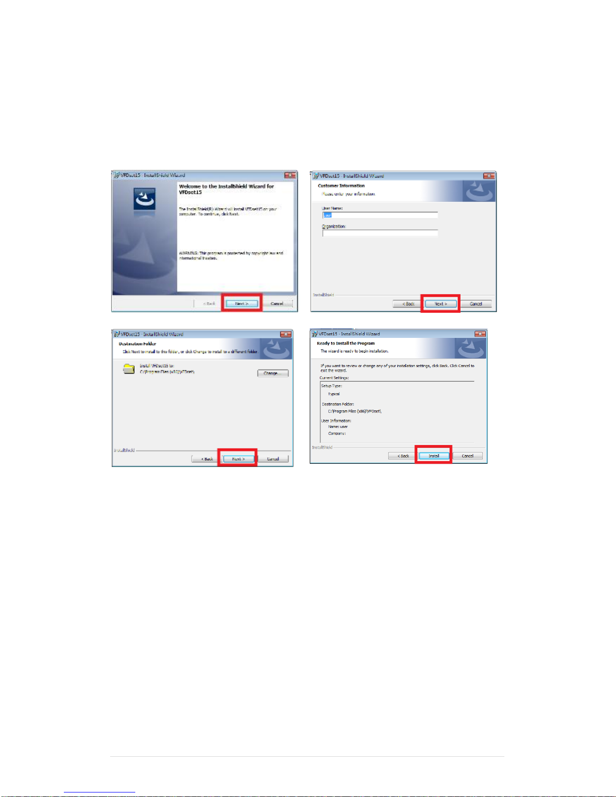
1. Power on VFD and waiting test page of EEPROM test, Baud rate and Command page.
Set up the customer display by " VFDset.exe”
2. Setup VFDset.exe software.
Page 95
Clientron PT6100 User Manual
Version: 1.0
95 | 111
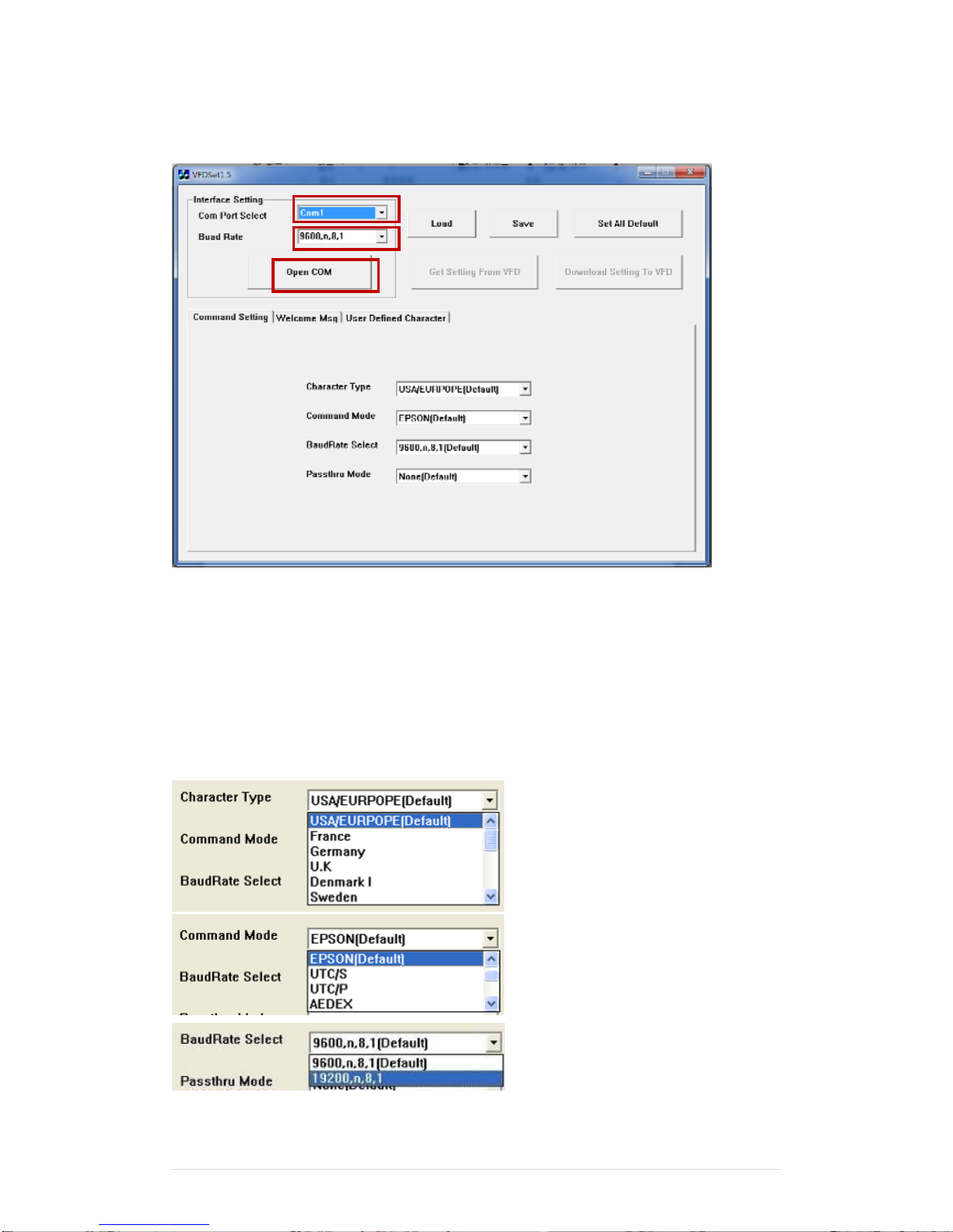
3. To execute “VFDset.exe” for setting up communication between software and VFD
module.
Please then follow the steps as shown in the above figure, the baud rate will show on states
page of VFD module (Note: You may check it when power on VFD module), then click “Open
COM” button.
4. “Get Setting from VFD” button to get all the settings from Clientron and it’ll refresh the
“VFDset.exe” software.
5. Select “Character Type”/ “Command Mode”/ “Baud Rate Select”/ “passthru Mode”.
1
2
3
Page 96
Clientron PT6100 User Manual
Version: 1.0
96 | 111
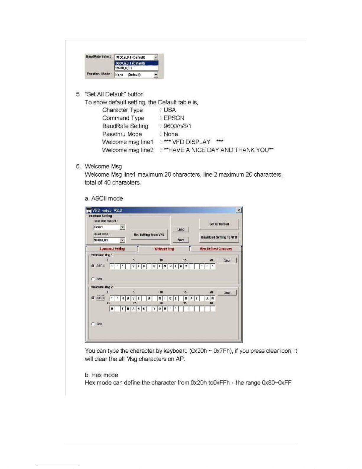
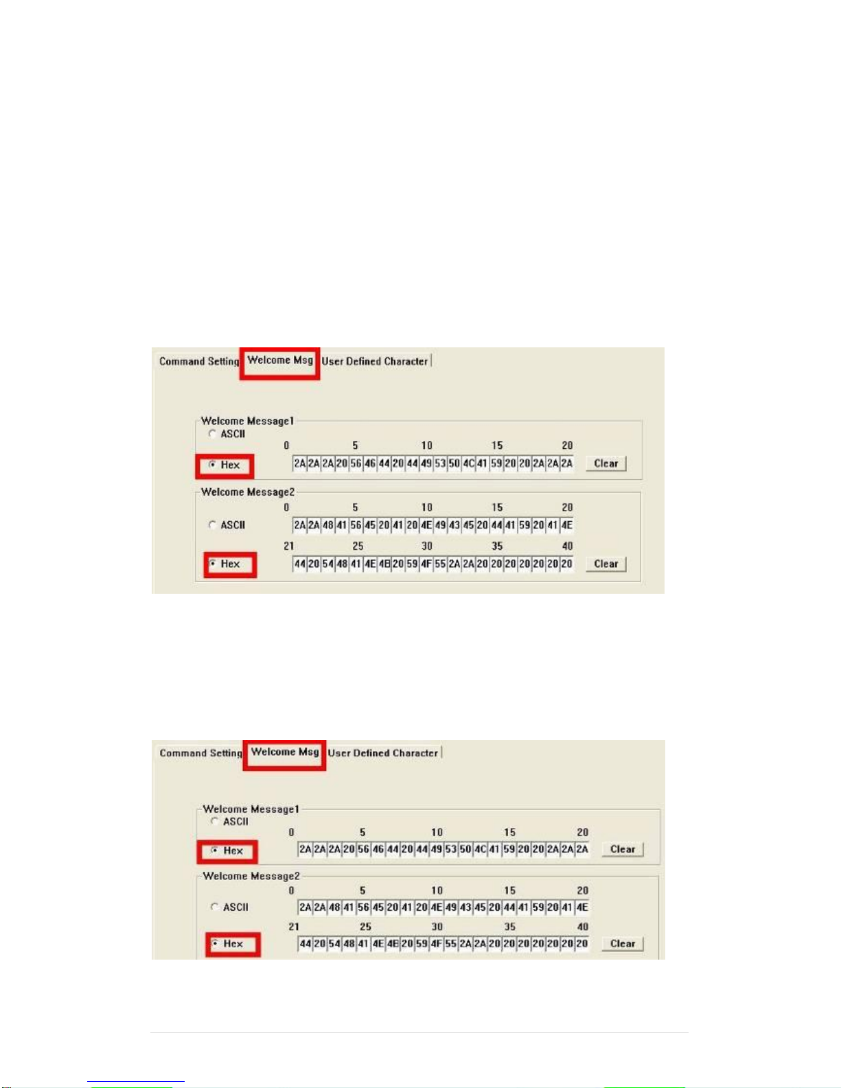
6. Click “Set All Default” button To show default setting, the Default table is
Character Type :USA
Command Type :EPSON/EURPOPE
Baud Rate Setting :9600/n/8/1
Pass-through Mode :None
Welcome msg line1 :*** VFD DISPLAY ***
Welcome msg line2 :**HAVE A NICE DAY AND THANK YOU **
7. Welcome Message
Welcome Message line1 maximum 20 characters, line 2 maximum 20 characters, total of
40 characters.
a. ASCII mode
You can type the character by keyboard (0x20h ~ 0x7Fh), if you press clear icon, it will
clear the all Message characters on AP.
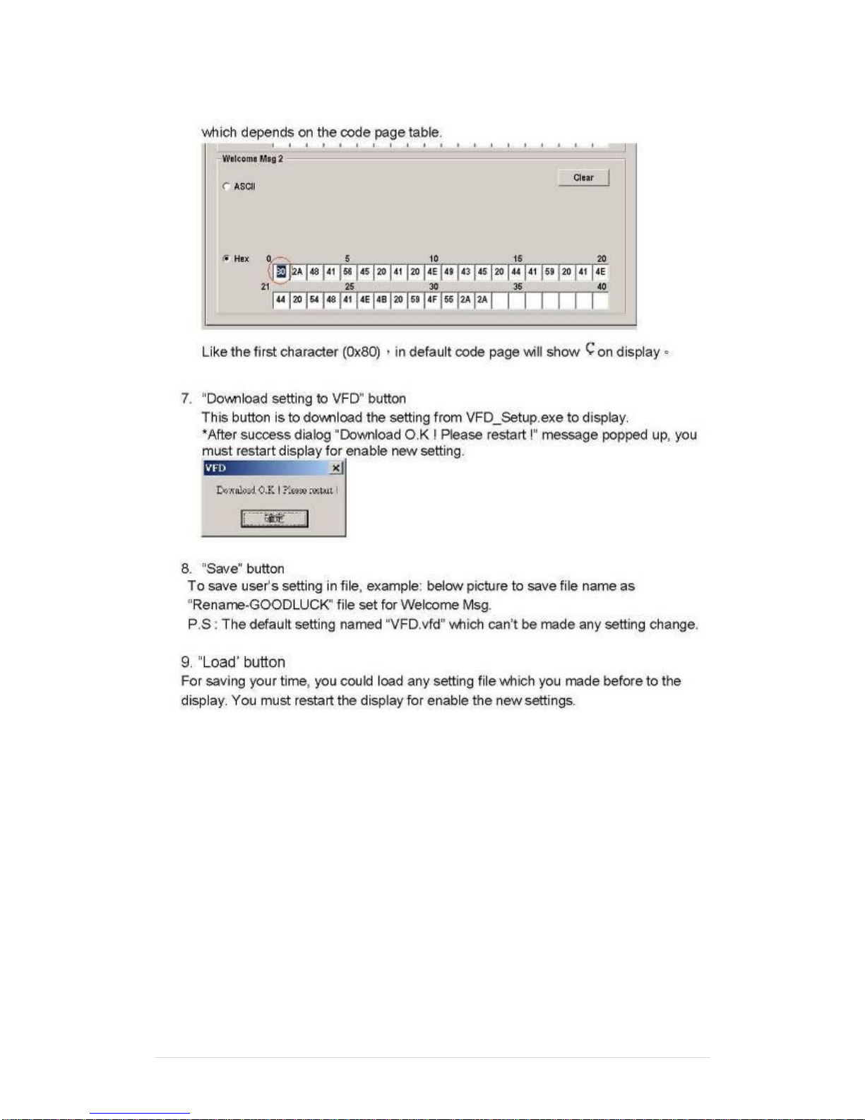
b. Hex mode
Hex mode can define the character from 0x20h to0xFFh,the range 0x80~0XFF which
depends on the code page table.
Like the first character (0x80),in default code page will show on VFD module.
Page 97
Clientron PT6100 User Manual
Version: 1.0
97 | 111
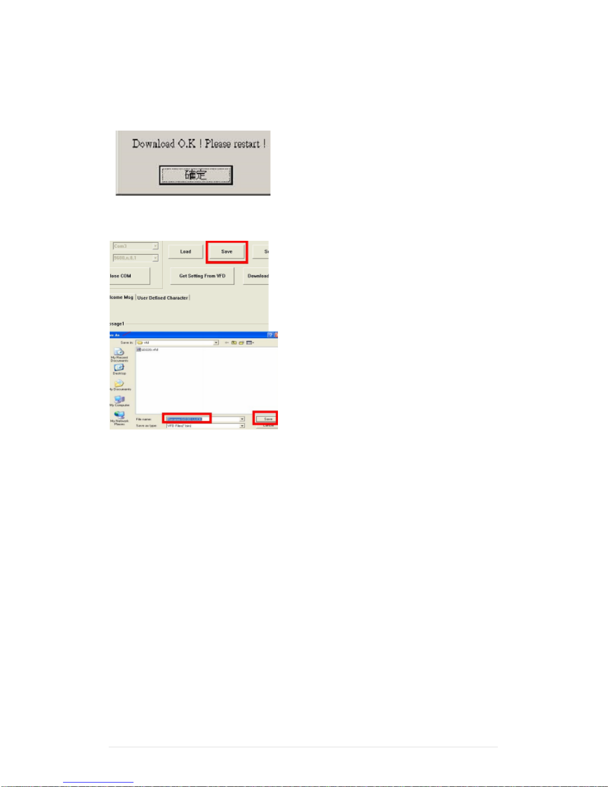
8. Click “Download setting to VFD” button
This button is to download the setting from VFDset.exe to VFD module. After success dialog
“Download O.K! Please restart!” message popped up. Please restart display for enable new
setting
9. Click “Save” button
To save user’s setting in file; for example, below picture to save file name as “GOODLUCK” file
set for Welcome Message.
Page 98
Clientron PT6100 User Manual
Version: 1.0
98 | 111
10. Click “Load’ button
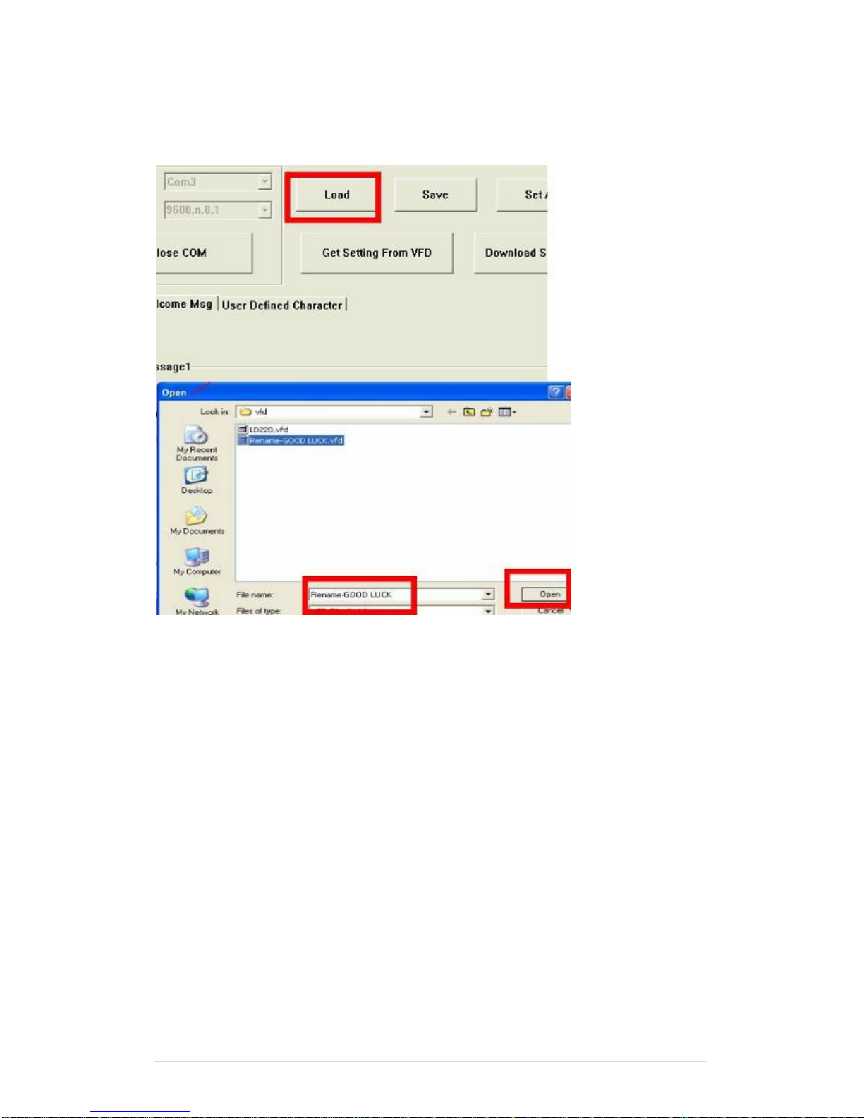
After saving, you must restart the utility here. Then load your setting rename-GOODLUCK.vfd.
Page 99
Clientron PT6100 User Manual
Version: 1.0
99 | 111
7
BIOS/Utility setup
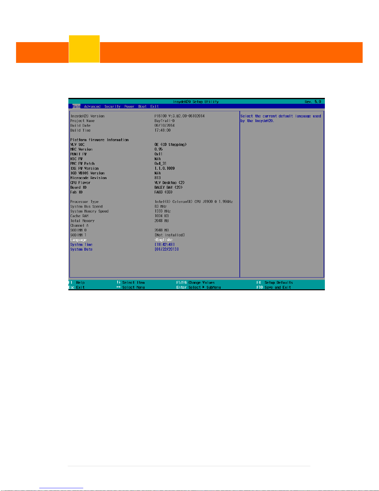
Press <DEL > / <F2> key to enter BIOS SETUP UTILITY when system boot up.
☆ Please press <DEL > / <F2> key tenderly and slowly.
BIOS/Utility setup
7
Page 100
Clientron PT6100 User Manual
Version: 1.0
100 | 111
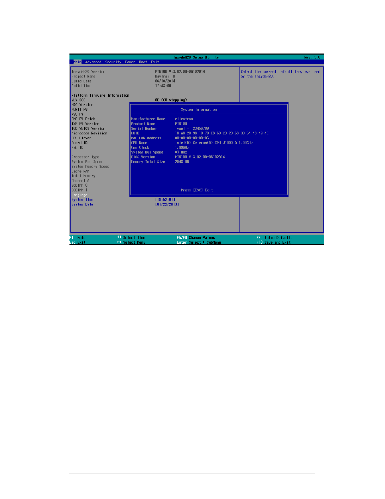
Press <F9> to view the system information
Date and Time
The Date and Time items show the current date and time on the computer. If you are running a
Windows OS, these items are automatically updated whenever you make changes to the
Windows Date and Time Properties utility.
WARNING!
Setting the wrong values in the sections below may cause the system to malfunction.
Make sure that the settings made are compatible with the hardware.
 Loading...