

Page 1
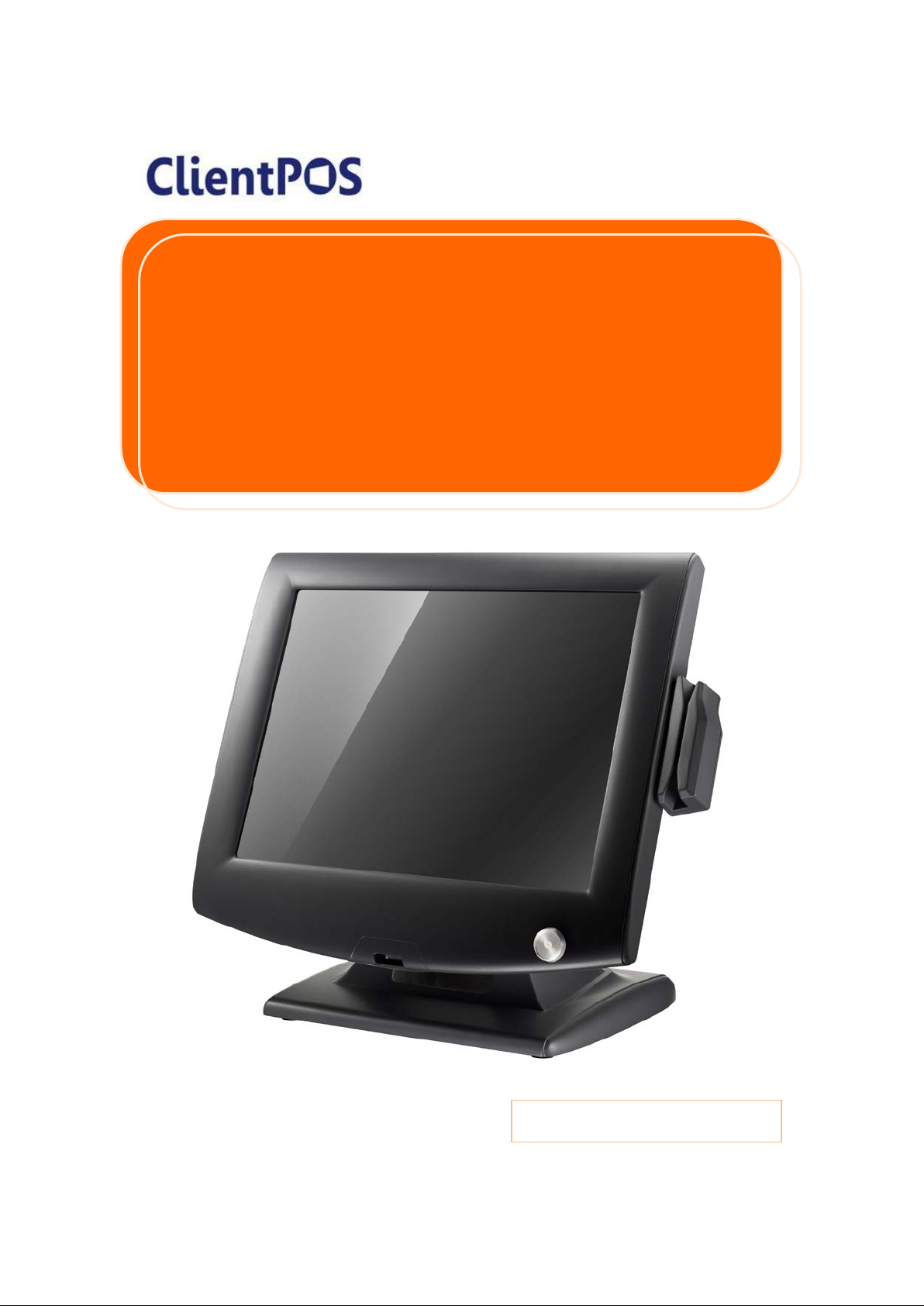
PT8000
P/N :
User Manual
Version: 1.0
Page 2

ClientPOS PT8000 User Manual
Version: 1.0
Copyright
Copyright 2012 Publishing. All Rights Reserved.
This manual, software and firmware described i n i t are copyrighted by their respective owners
and protected under the laws of the Universal Copyright Convention. You may not reproduce,
transmit, transcribe, store in a retrieval system, or translate into any language, in any form or
by any means, electronic, mechanical, magnetic, optical, chemical, biological, molecular,
manual, or otherwise, any part of this publication without the express written permission of the
publisher.
All products and trade names described within are mentioned for identification purpose only.
No affiliation with or endorsement of the m anufacturer is made or implied. Product names and
brands appearing in this manual are registere d trademarks of their respective companies.
The information published herein has been checked for accuracy as of publishing time. No
representation or warranties regarding the fitness of this document for any use are made or
implied by the publisher. We reserve the right to revise this document or make changes in the
specifications of the product described therei n at any time wit hout noti ce and without obligation
to notify any person of such revision or change.
II
Page 3

ClientPOS PT8000 User Manual
Version: 1.0
Safety Instructions
1. Read these instructions carefully. Keep these i nstructions for future reference.
2. Please disconnect this equipment from AC out l et before cleaning. Don’t use liquid or
sprayed detergent for cleaning. Use moisture sh eet or cloth for cleaning.
3. Please keep this equipment from humidity.
4. Lay this equipment on a reliable surface when install. A drop or fall could cause injury.
5. Make sure power cord such a way that people can n ot step on it. Do not place anything
over the power cord.
6. All cautions and warnings on the equipment should be noted.
7. If the equipment is not used for long time, disconnect the equipment from main to avoid
being damaged by transient over voltage.
8. Never pour any liquid into opening, this coul d cause fire or electrical shock.
9. If one of the following situations arises, get the equipment checked by a service
personnel:
a. The power cord or plug is damaged.
b. Liquid has penetrated into the equipment.
c. The equipment has been exposed to moisture.
d. The equipment does not work well or you can not get it work according to user
manual.
e. The equipment has dropped and damaged.
10. Do not leave this equipment in an environment un condi tione d, sto rage tem per a ture belo w
-20°C or above 60°C, it may damage the equipment.
11. Unplug the power cord when doing any service or adding optional kits.
Lithium Battery Caution:
Danger of explosion can happen if the battery i s i ncorrectly replaced. Replace only the original
or equivalent type recommended by the manufacture. Dispose used batteries according to the
manufacture’s instructions.
Do not remove the cover, and ensure no user servi ceable components are inside. Take the
unit to the service center for service and repair.
III
Page 4

ClientPOS PT8000 User Manual
Version: 1.0
CE Notice
This device complies with the requirements of the CE directive.
FCC Notice
This equipment has been tested and found t o comply wit h the lim its f or a Class B digital dev ice,
pursuant to Part 15 of the FCC rules. These li m i ts are designed to provide reasonable
protection against harmful interference in a residential installation. This equipment generates
uses and can radiate radio frequency energy and, i f not installed and used in accordance with
the instructions, may cause harmful interfere nce to radio communications. However, there is
no guarantee that interference will not occ ur i n a particular installation. If this equipment does
cause harmful interference to radio or television r ecep tion, which can be deter mined by turning
the equipment off and on, the user is encouraged to try to correct the interference by one or
more of the following measures:
Reorient or relocate the receiving antenna.
Increase the separation between the equipment and receiver.
Connect the equipment into an outlet on a circuit different from that to which the receiver is
connected.
Consult the dealer or an experienced radio/ T V technician for help.
Shielded interface cables must be used in orde r to comply with emission limits.
Changes or modifications not expressly approved by the party responsible for compliance
could void the user’s authority to operate the equi pment.
WEEE Notice
This appliance is labeled in accordance wit h European Dir ective 2002/ 96/EC concerning waste
electrical and electronic equipment (WE EE). The Directive determines the framework for the
return and recycling of used appliances as appli cable throughout the European Union. This
label is applied to various products to indicate that the product is not to be thrown away, but
rather reclaimed upon end of life per this Dire ct i ve.
IV
Page 5

ClientPOS PT8000 User Manual
Version: 1.0
Table of Contents
Copyright…………………………………………………….
Safety Instructions…………………………………………
CE /FCC/WEEE Notice……………………………………..
1. Packing List………………………………………………
1-1 Standard Accessories………………………………………..
1-2 Optional Accessories………………………………………...
2. System View ……………………………...………. ……
2-1 Rear View……………………………………………………..
2-2 Specification…………………………………………………..
2-3 Internal Layout………………………………………………..
3. Pin Definition……………………………………………...
4. Rear I/O Interface…………………..……………………
II
III
IV
P1
P1
P1
P2
P2
P3
P4
P5
P9
5. System Assembly & Disassembly……………………
5-1 HDD…………………………………………………………....
5-2 RAM…………………………………………………………...
5-3 CFAST………………………………………………………...
5-4 MSR…………………………………………………………...
5-5 Internal VFD…………………………………………………..
5-6 Wi-Fi…………………………………………………………..
6. Device Driver Installation………………………………
6-1 Resistive Type Touch Panel …………………....…………..
6-2 MagStripe Card Reader Configuration Utility…………...
6-3 Fingerprint Reader………………………………………….
6-4 RFID...………………………………………………………...
6-5 Internal VFD………………………………………………….
P11
P11
P12
P13
P13
P14
P15
P17
P17
P23
P29
P38
P47
6-6 i-Button Reader Configuration Utility…………………..…..
V
P51
Page 6

ClientPOS PT8000 User Manual
8. LCD Surface Cleaning…………………………………..
P72
Version: 1.0
6-7 Installation and Testing of Smart Card Reader……………
7. BIOS/Utility Setup………………………………………..
7-1 Advanced……………………………………………………..
7-1-1 ACPI Configuration…………………………………
7-1-2 S5 RTC Wake Settings…………………………….
7-1-3 CPU Configuration………………………………….
7-1-4 IDE Configuration…………………………………...
7-1-5 IT8783F Super IO Configuration………………….
7-1-6 Parallel Port Configuration…………………………
7-2 Chipset………………………………………………………..
7-2-1 Southbridge Configuration…………………………
7-3 Boot……………………………………………………………
7-4 Security……………………………………………………….
7-5 Save & Exit……………………………………………………
P54
P58
P59
P60
P61
P62
P63
P64
P66
P67
P68
P69
P70
P71
VI
Page 7
ClientPOS PT8000 User Manual
Packing List
1
Version: 1.0
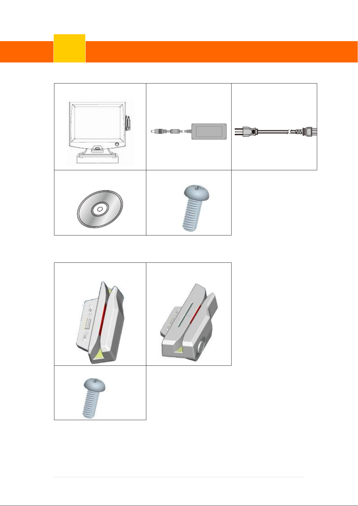
1-1 Standard Accessories
a.
d.
1-2 Optional Accessories
b.
e.
c.
a. System (with stand)
b. Power Adapter
c. Power Cord
d. Driver Bank
e. M3 Screw x2
a.
c.
b.
1. Single MSR
2. 3 IN 1 MSR
3. Screw x2
1| 72
Page 8
ClientPOS PT8000 User Manual
System View
2
1 2 3
4 5 6
7 8 9
10
11
13
14
12
Version: 1.0
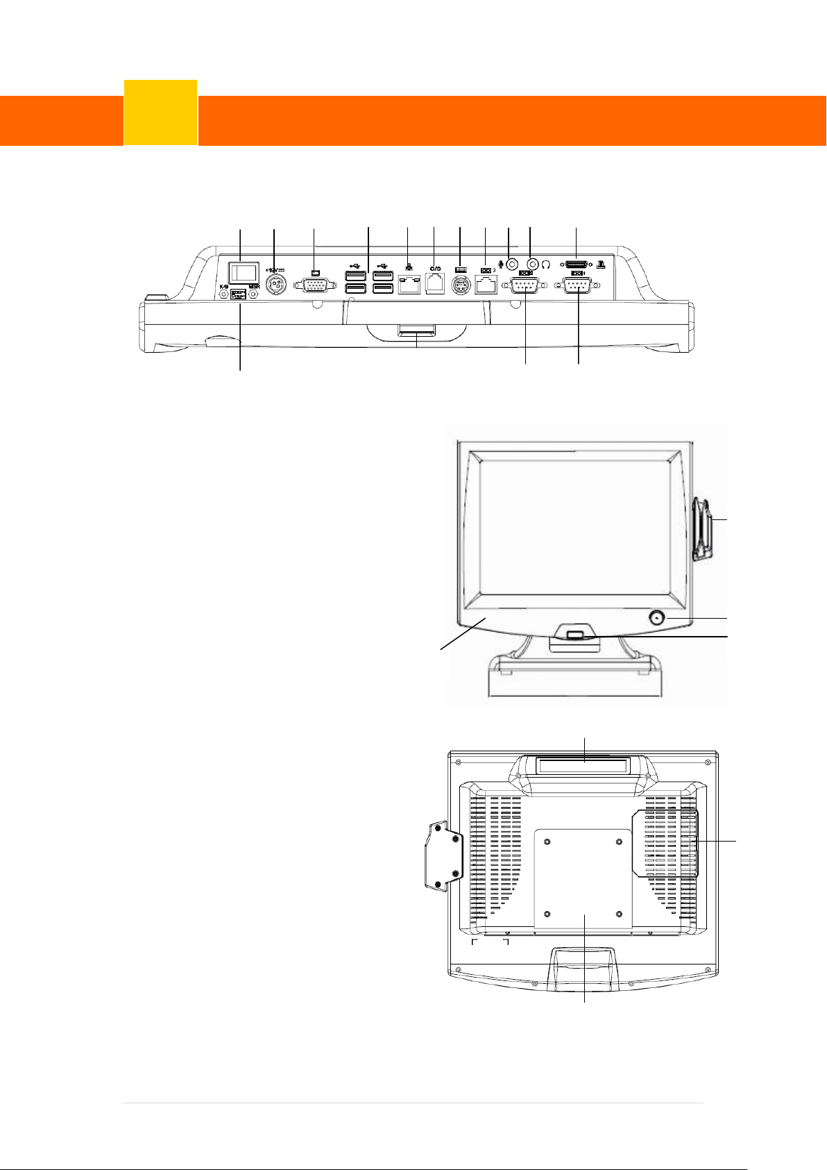
2-1 Rear View
Item
1. Power Switch
2. 19V DC-in lock connector
3. VGA
4. USB x4
5. RJ45(LAN)
6. RJ11 for cash drawer
7. PS/2
8. RJ45(COM3 for External
VFD)
9. Mic-in
10. Line-out
11. LPT(Option)
12. PS/2 MSR Switch
Gear(Option)
13. COM2
14. COM1
15. MSR(Option)
16. iButton(Option)
17. 1D/2D Barcod e
Scanner(Option)
18. RFID(Option)
19. LCM/VFD(Option)
20. HDD / CFast
21. VESA Mount
18
19
☆ Please make sure 19V DC plug
in the right direction before
plugging in DC jack.
15
16
17
20
21
2 | 72
Page 9

ClientPOS PT8000 User Manual
System View
2
Version: 1.0
2-2 Specification
Processor
Chipsets: North Bridge/South Bridge
Memory
Audio
Network
USB
Storage
BIOS
Power
Thermal Solution
Dimension
Operating Temperature
Storage Temperature
Intel Atom D2550 1.86GHZ
Intel NM10
SO-DIMM socket supports DDR3 up to 4GB
Line-out/Mic-in
RJ45 10/100/1000 Base-T
4*USB 2.0
CFast card / 2.5” SATA HDD / SSD
AMI UEFI BIOS Support
DC 19V 90/65W Adaptor
Fan-less
37.54(W) x 37.23(H) x 26.89 (D) cm
0°C ~ 40°C
-20°C ~ 60°C
Storage Humidity
Display
LCD Panel Size
Resolution
Backlight
Brightness
Touch Panel
Note:
• Intel™ Cedarview CPU does not support 64-bit OS, therefore 64-bit Microsoft Windows®
Embedded POSReady 7 and 64-bit Microsoft Windows® 7 are not supported on PT8000.
• Current Intel™ XP Pro / POSReady 2009 graphics driver for Cedarview platform does not
support dual display.
• Please avoid excessive shock during HDD operating.
-20% ~ 80%, non-condensing
15-inch TFT Active Matrix Display
1024*768 Pixels
LED CCFL
400 cd/m2 250 cd/m2
5-Wire Analog Resistive Type
3 | 72
Page 10
ClientPOS PT8000 User Manual
System View
2
Front Side
Version: 1.0
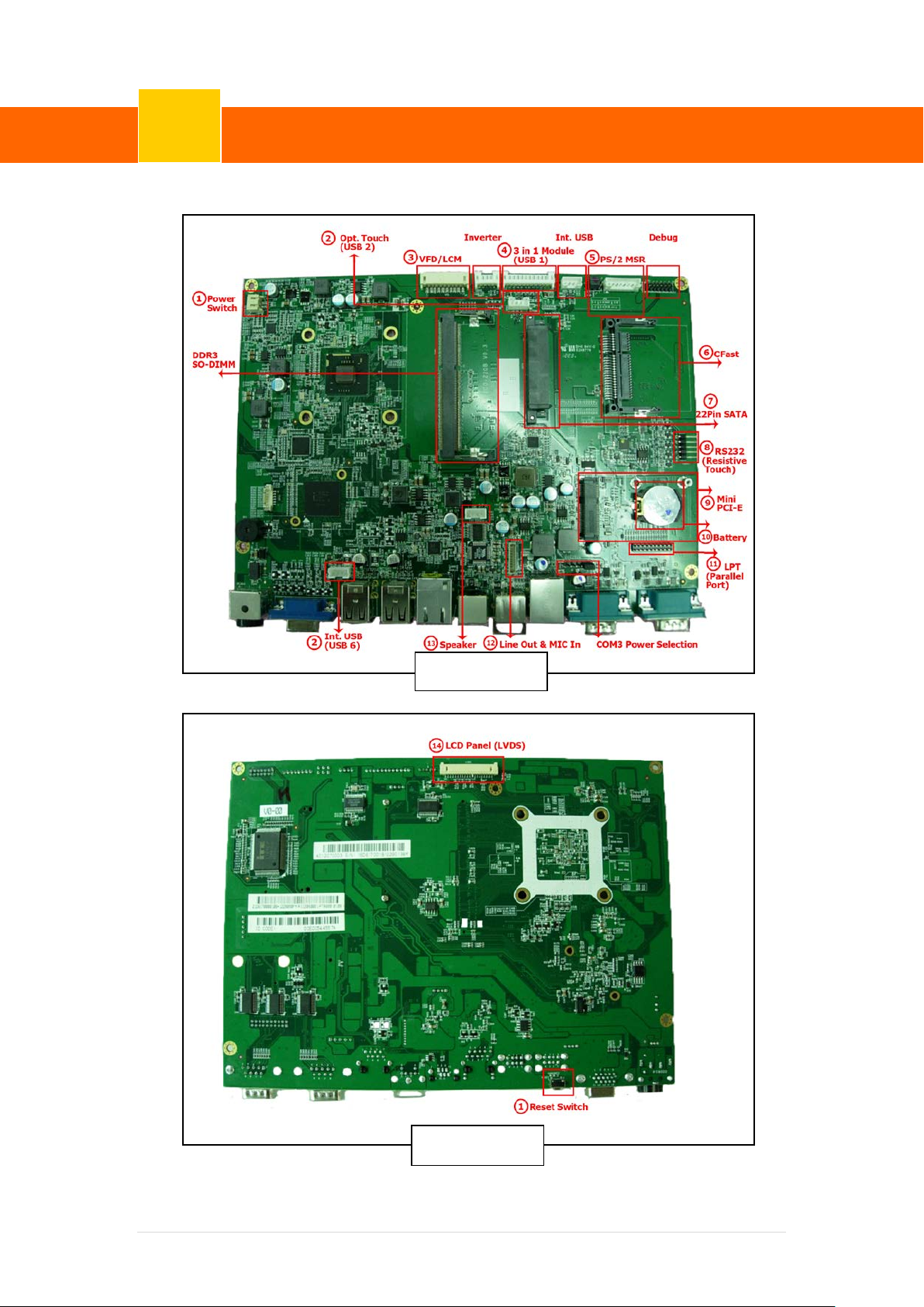
2-3 Internal Layout
Backside
4 | 72
Page 11

ClientPOS PT8000 User Manual
Pin Definition
3
Version: 1.0
1. Power Switch (CN1)
Power switch (CN1)
Pin Signal
1 PWRBTN_N
2 GND
2. Internal connector fo USB6
Pin Signal
1 5V
2 D3 D+
4 GND
3. VFD (COM4)
Pin Signal Pin Signal
1 5V 6 CTS
2 DSR 7 TXD
☆ USB 6 is connected to one hub, and it
is for iButton, RFID and barcode
scanner.
3 Ground 8 RXD
4 DTR 9 Ground
5 RTS 10 12V
4. Internal connector for 3 in 1 module (USB 1)
Pin Signal Pin Signal Pin Signal
1 5V 5 HUB_P1_DP 9 HUB_P3_DP
2 5V 6 HUB_P2_DN 10 GND
3 GND 7 HUB_P2_DP 11 3.3V
4 HUB_P1_DN 8 HUB_P3_DN 12 3.3V
5. PS/2 MSR (CN9)
Pin Signal Pin Signal Pin Signal
1 5V 4 GND 7 K/B Clock
2 K/B Data 5 NC 8 MSR K/B Clock
3 MSR K/B Data 6 GND
5 | 72
Page 12

ClientPOS PT8000 User Manual
Pin Definition
3
Version: 1.0
Jumper setting JP2
Pin Signal Pin Signal Pin Signal
1 K/B Data 3 MSR K/B Data 5 NC
2 K/B Clock 4 MSR K/B Clock 6 NC
6. CFast connector
Pin Signal Pin Signal Pin Signal Pin Signal
1 GND 7 GND 13 NC 19 NC
2 TX 8 CDI 14 GND 20 V3.3
3 TX# 9 GND 15 NC 21 V3.3
4 GND 10 NC 16 NC 22 GND
5 RX# 11 NC 17 NC 23 GND
6 RX 12 NC 18 NC 24 CDO
7. 22Pin SATA connector
Pin Signal Pin Signal Pin Signal Pin Signal
1 GND 7 GND 13 GND 19 GND
2 TX 8 V3.3 14 V5 20 V12
3 TX# 9 V3.3 15 V5 21 V12
4 GND 10 V3.3 16 V5 22 V12
5 RX# 11 GND 17 GND
6 RX 12 GND 18 ACT-/SPIN
8. RS232 type COM(For Resistive Touch)
Pin Signal
1 UR
2 LR
3 SG
4 UL
5 LL
6 | 72
Page 13

ClientPOS PT8000 User Manual
Pin Definition
3
Version: 1.0
9. Mini PCI-E
Pin Signal Pin Signal
1 Wake# 9 GND Pin Signal Pin Signal
2 +3.3V 10 RSVD 17 RSVD 35 GND
3 RSVD 11 REFCLK- 18 GND 36 USB D4 GND 12 RSVD 19 RSVD 37 RSVD
5 RSVD 13 REFCLK+ 20 W_Disable# 38 USB D+
6 1.5V 14 RSVD 21 GND 39 RSVD
7 CLKREQ# 15 GND 22 PERST# 40 GND
8 RSVD 16 RSVD 23 PER_ND 41 RSVD
24 +3.3V_AUX 42 LED_WWAN#
25 PER_PD 43 RSVD
26 GND 44 LED_WLAN#
27 GND 45 RSVD
28 1.5V 46 LED_WPAN#
29 GND 47 RSVD
30 SMB_CLK 48 1.5V
Key
31 PET_ND 49 RSVD
32 SMB_DATA 50 GND
33 PET_PD 51 RSVD
34 GND 52 3.3V
10. Battery
Pin Signal Pin Signal
1 VRTC 2 GND
11. LPT (J7)
Pin Signal Pin Signal Pin Signal
1 STB# 8 SLIN# 15 PD6
2 AFD# 9 PD3 16 GND
3 PD0 10 BUSY 17 PD7
4 ERR# 11 PD4 18 GND
5 PD1 12 PE 19 ACK#
6 INIT# 13 PD5 20 GND
7 PD2 14 SLCT
7 | 72
Page 14

ClientPOS PT8000 User Manual
Pin Definition
3
Version: 1.0
12. Line Out & Mic In (Audio CN8)
Pin Signal Pin Signal
1 GND 6 Line_Out L
2 MIC_Th_L 7 AMP-L
3 MIC_Th_R 8 AMP-R
4 GND 9 Line_Out R
5 GND 10 GND
13. Speaker (CN5)
Pin Signal
1 L+
2 L3 R+
4 R-
14. LCD Panel (LVDS)
LVDS connector
Pin Signal Pin Signal Pin Signal
1 GND 11 GND 1 12V
2 GND 12 LVDS_TX1_DP 2 Ground
3 NC 13 LVDS_TX1_DN 3 No connect
4 NC 14 GND 4 Back light control
5 GND 15 LVDS_TX0_DP 5 Back light enable
6 LVDS_CLK_DP 16 LVDS_TX0_DN
7 LVDS_CLK_DN 17 GND
Back light(Inverter)
8 GND 18 GND
9 LVDS_TX2_DP 19 LCD_VDD
10 LVDS_TX2_DN 20 LCD_VDD
8 | 72
Page 15

ClientPOS PT8000 User Manual
Rear I/O Interface
4
COPY TEST.TXT COM6
Version: 1.0
1. COM Port
Pin Signal Pin Signal Pin Signal
1 DCD 4 DTR 7 RTS
2 RXD 5 Ground 8 CTS
3 TXD 6 DSR 9 5V/12V/Ring
**COM1 and COM2 Pin9 function selection by BIOS Item
2. Cash Drawer(COM 6)
Pin Signal Pin Signal Pin Signal
3 Open/close detection
1 Ground
5 NC
switch on drawer
Drawer kick-out
2
driver signal
4 +12VDC for drawer
6 Ground
kick-out supplied
Example DOS COMMAND for Cash Drawer:
1. Create the file: TEST.TXT
2. Input below contents in TEST.TXT
CONTEXT-"000.0”
MODE COM6:300
3. Run COMMAND under DOS mode
3. VGA
Pin Signal Pin Signal Pin Signal Pin Signal
1 Red 5 GND 9 5V 13 HSYNC
2 Green 6 GND 10 GND 14 VSYNC
3 Blue 7 GND 11 NC 15 DDC_CLK
4 NC 8 GND 12 DDC_DAT
4. PS/2
Pin Signal Pin Signal
1 K/B Data 4 VCC
5. DC Jack
Pin Signal
1 19V
2 Mouse Data 5 K/B Clock
3 GND 6 Mouse Clock
6. 2 layer USB Port
Pin Signal Pin Signal
1 5V 3 D+
2 D- 4 GND
2 GND
3 19V
9 | 72
Page 16
ClientPOS PT8000 User Manual
Rear I/O Interface
4
☆
ON
12
Only K/B
V X
Only MSR
X V
V:Function
K/B + MSR
X V
X: Forbidden
☆
☆☆
VFD)
Version: 1.0
7. Giga LAN
Pin Signal Pin Signal Pin Signal
1 VCC 6 MDI2+ L1 LED1(Green +, Orange -)
2 MDI0+ 7 MDI2- L2 LED1(Green -, Orange +)
3 MDI0- 8 MDI3+ L3 LED2(Yellow +)
4 MDI1+ 9 MDI3- L4 LED2(Yellow -)
5 MDI1- 10 GND
** LED1 : Link signal ** LED2 : Action signal
8. RJ45 type COM3
Pin Signal Pin Signal
1 5V/12V 5 RTS Pin Signal
2 DSR 6 CTS 1 5V
3 Ground 7 TXD 2 NRI#A
4 DTR 8 RXD 3 NC
4 NRI#A
5 12V
Jumper for COM3 Voltage setting
○
1
JP1
◎ ◎ ◎ ◎
NOTICE:
COM 3 port. Warning!! COM3 ( RJ45 Connector) for external VFD use only. Never
use on network device. If you are using on the network device will cause the
device damaged.
COM 3 port will be inactive if POS has internal VFD. (Alternative of COM 3 or internal
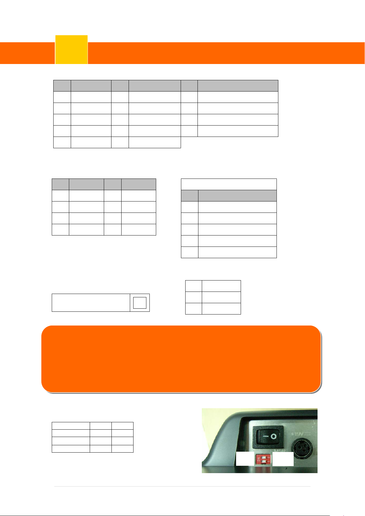
9. PS/2 MSR Switch
Sliding both buttons toward the same side.
5V/12V Jumper selection (JP1)
JP1
5V
1-2
12V
4-5
K/B
10 | 72
MSR
Page 17
ClientPOS PT8000 User Manual
System Assembly & Disassembly
5
2
HDD bracket
67D200418-000B
1
3 4 5
6
7
Version: 1.0
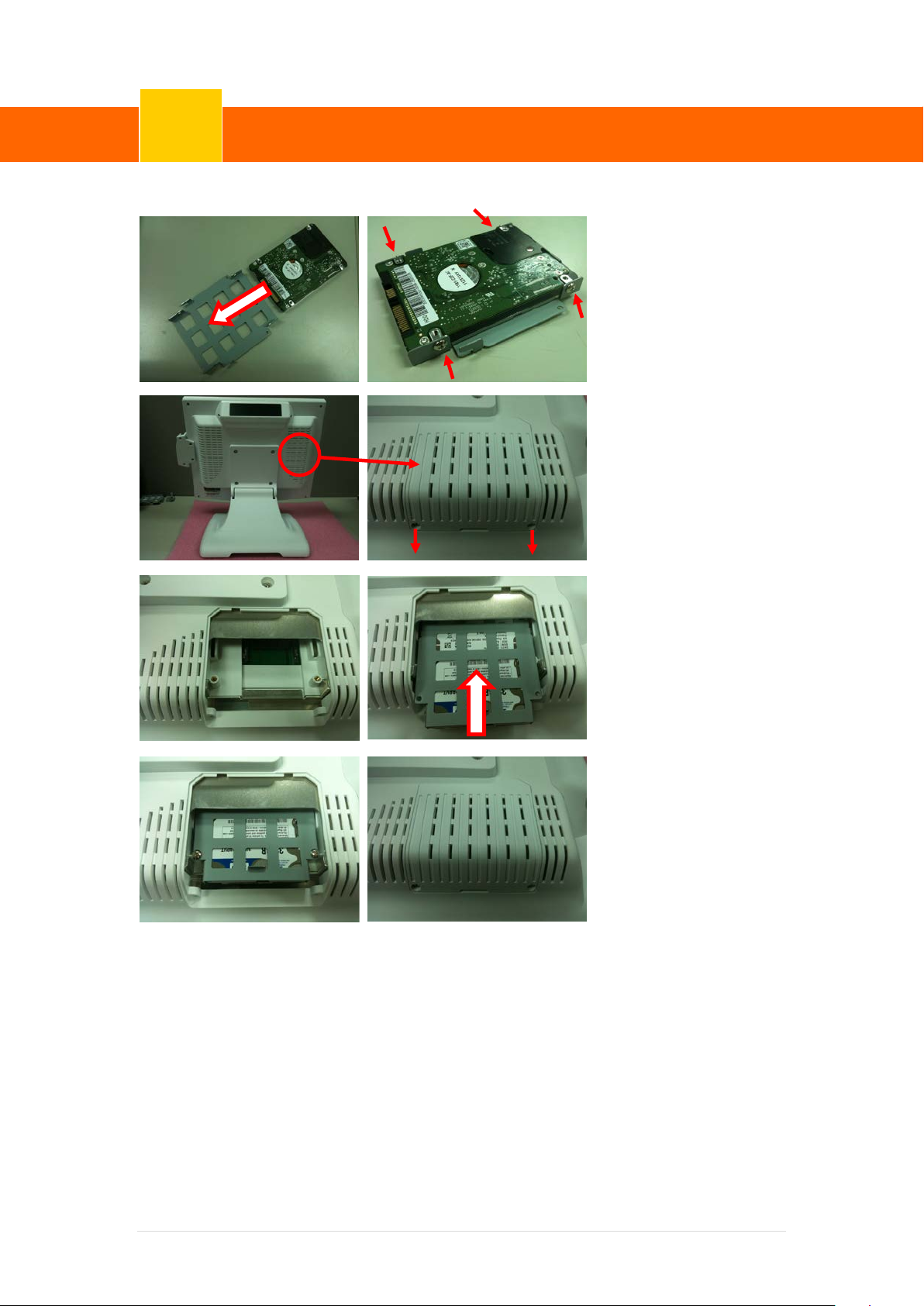
5-1 HDD
1. Put the HDD on the
HDD bracket
(67D200418-000B)
2. Fasten the 4 M3 screws
(64D030044-100B)
3. Unscrew 2 M3 screws
(64D030060-200T)
4. Unscrew the HDD cover
5. Fabricate HDD
W/bracket in HDD
holder
6. Fasten the 2 M3 screws
(64D030044-100B)
7. Fasten the 2 M3 screws
11 | 72
Page 18
ClientPOS PT8000 User Manual
System Assembly & Disassembly
5
3
6
7
5 2 4
1
Version: 1.0
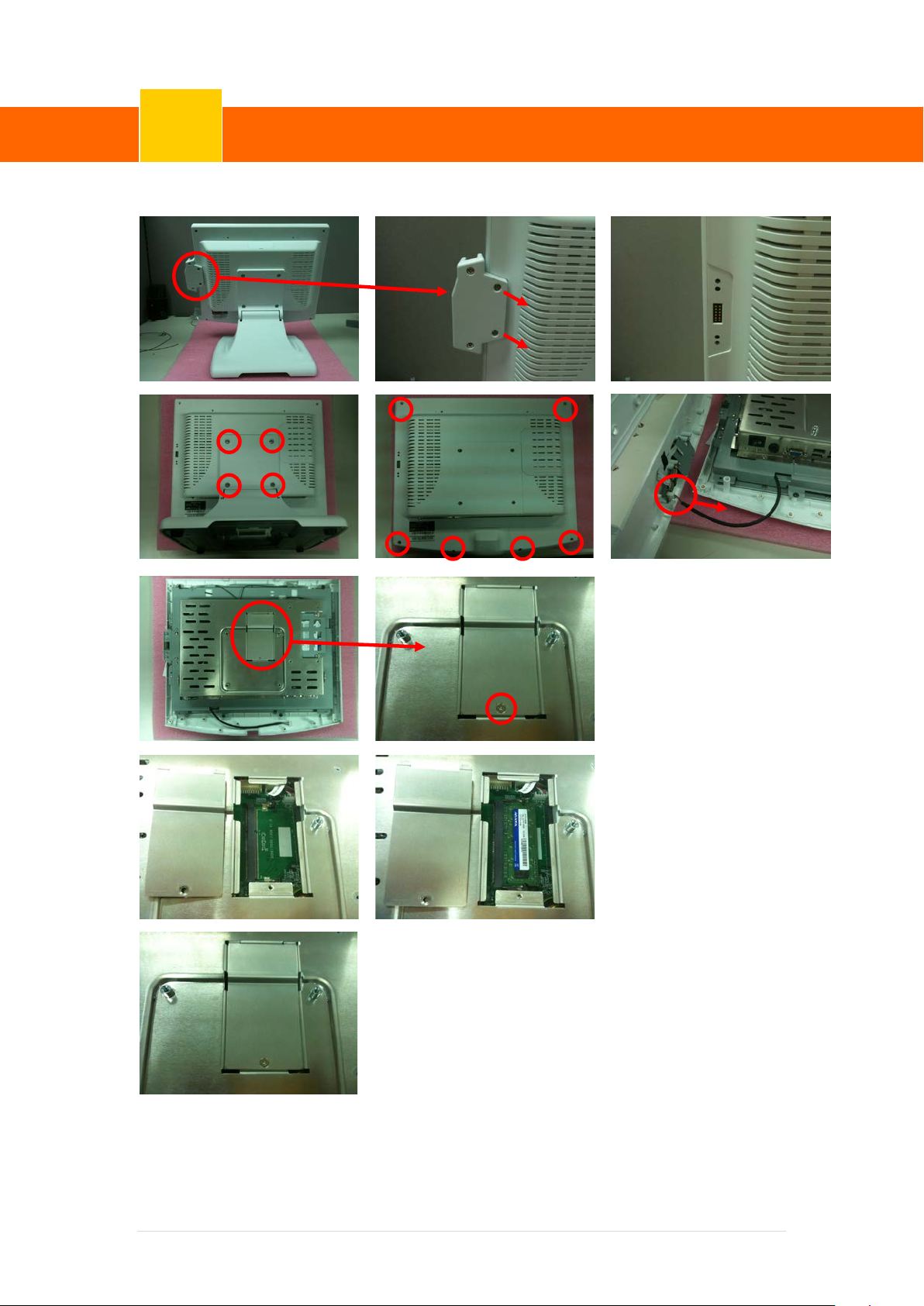
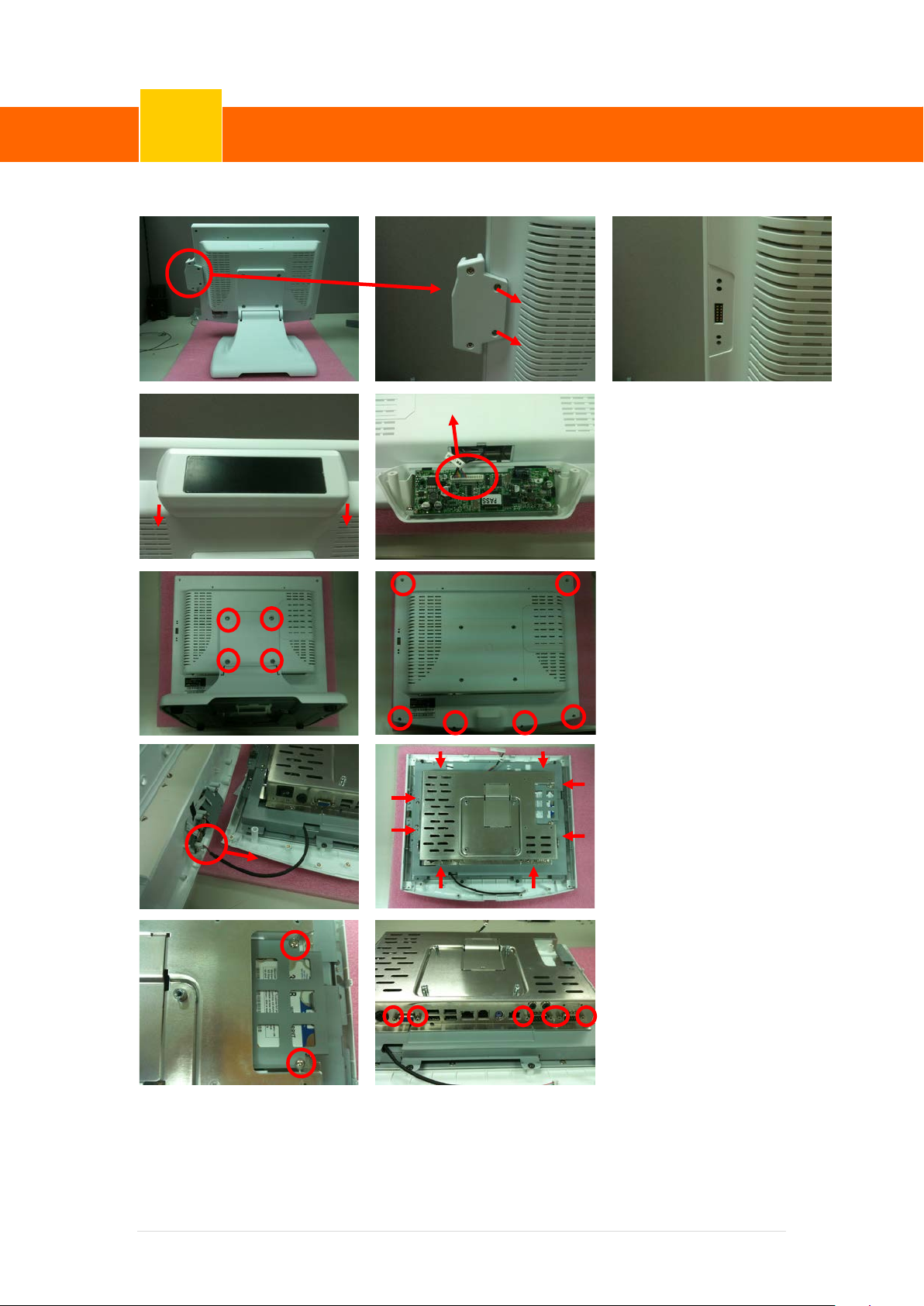
5-2 RAM
1. Unscrew 2 M3 screws
(64DA30104-100B) and
remove MSR
2. Unscrew 4 M4 screws
(64D040081-100B) and
remove the stand.
3. Unscrew 6 M4 screws
(64D030060-200T) and
remove the panel back
4. Remove the scanner cable
5. Unscrew 1 M3 screws
(64D730041-100B)
6. Remove RAM door and
install the RAM
7. Put the RAM door back.
12 | 72
Page 19
ClientPOS PT8000 User Manual
System Assembly & Disassembly
5
1
2
3 1 2
Version: 1.0
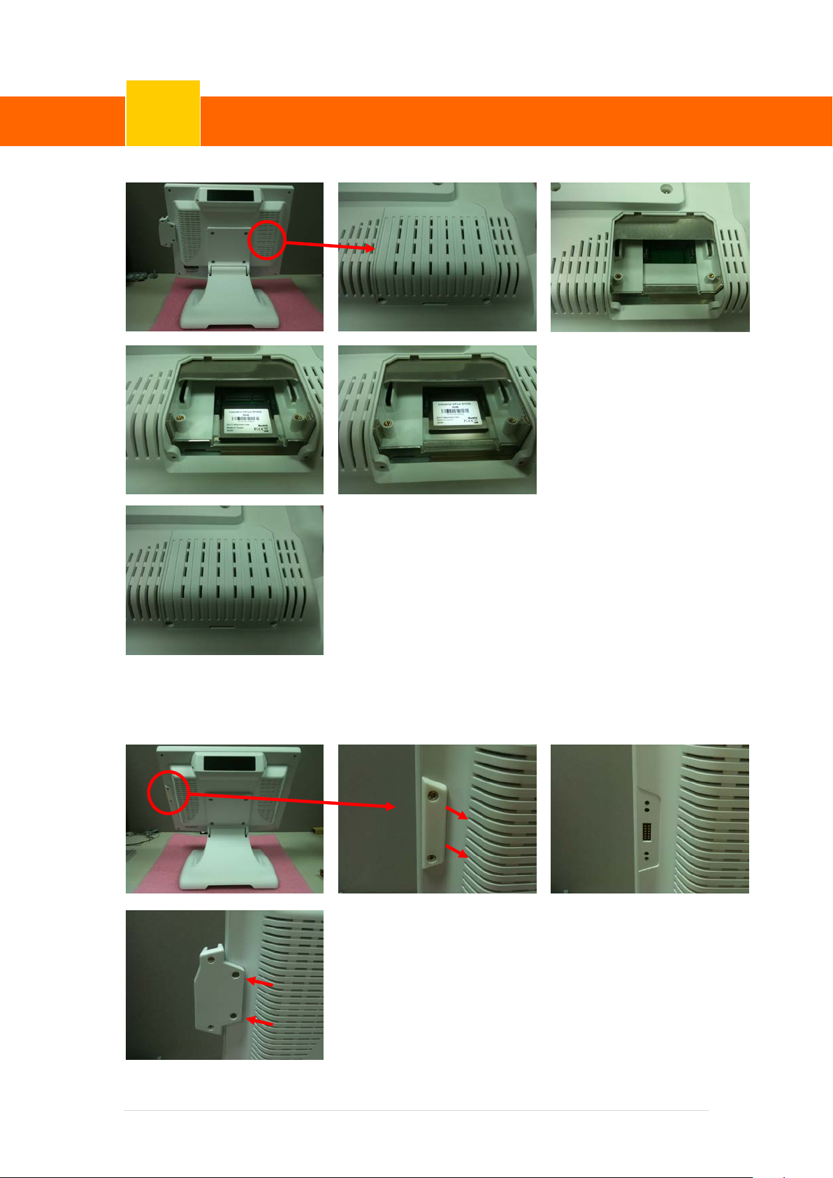
5-3 CFAST
5-4 MSR
1. Unscrew 2 M3 screws
(64D030060-200T) and
remove the HDD cover
2. Insert CFAST card
3. Reinstall the HDD cover
and secure it with screws
1. Unscrew 2 M3 screws (64D030060-200T)
2. Install MSR with screws.
13 | 72
Page 20
ClientPOS PT8000 User Manual
System Assembly & Disassembly
5
1 2 3
4
Version: 1.0
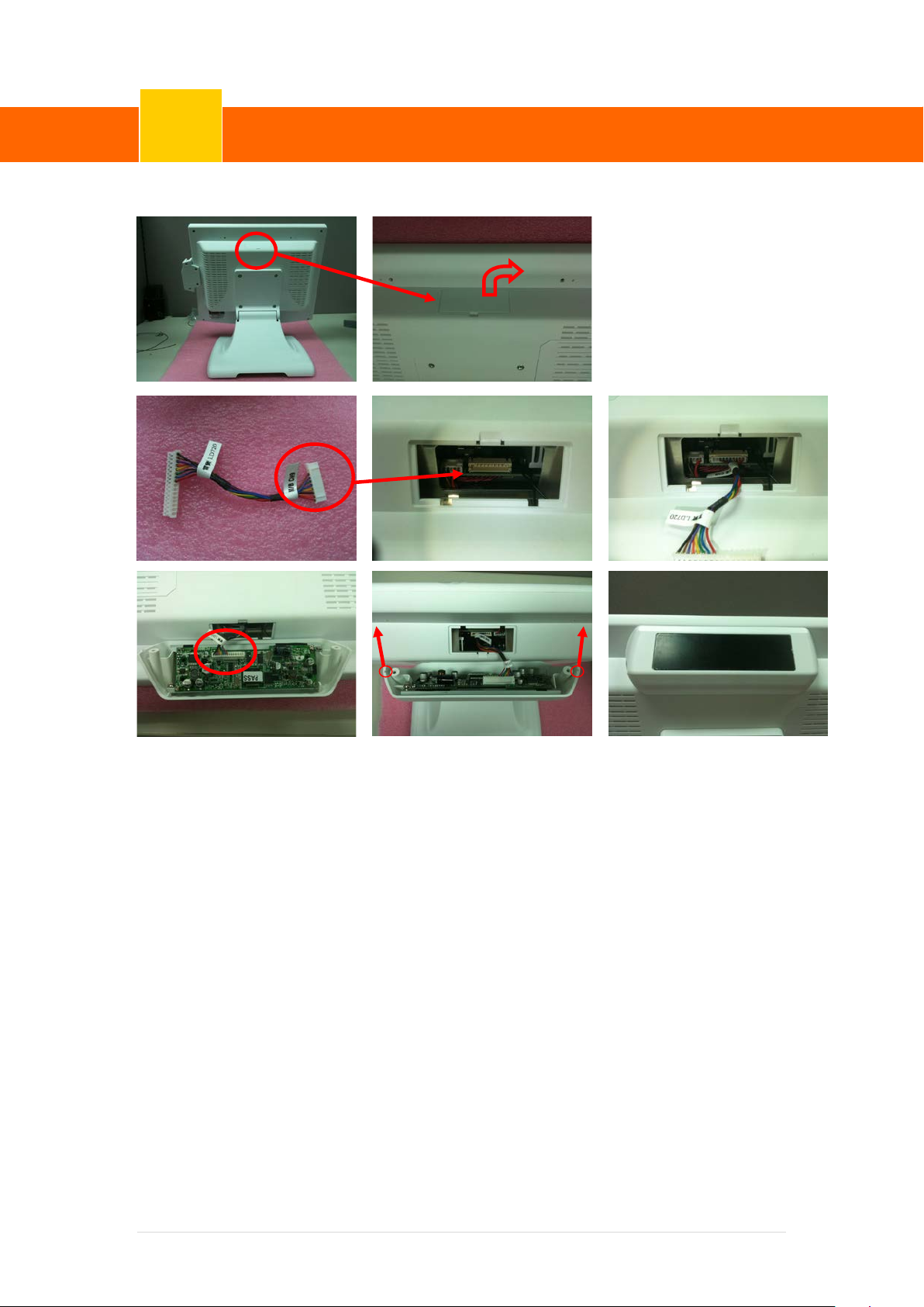
5-5 VFD
1. Remove VFD
door(68D640000-000B)
2. Plug M/B side of VFD cable
(35D510528-000B) into the
motherboard
3. Plug the VFD cable (35D510528-000B) into the VFD device
4. Install VFD with screws.
14 | 72
Page 21
ClientPOS PT8000 User Manual
System Assembly & Disassembly
5
1
2 3 4 5 6 7 8
Version: 1.0
5-6 WLAN
1. Unscrew 2 M3 screws
(64DA30104-100B) and
remove MSR
2. unscrew 2 M3 screws
(64D030060-200T) and
remove the VFD cable from
the VFD module
3. Unscrew 4 M4 screws
(64D040081-100B) and
remove the stand.
4. Unscrew 6 M3 screws
(64D030060-200T) and
remove the panel back
5. Disconnect the scanner
cable
6. Unscrew 8 M3 screws
(64D730041-100B)
7. Unscrew 2 M3 screws
(64D730041-100B) and
remove the HDD with
bracket
8. Unscrew 6 screws
(64D730041-100B) and
remove the shield cover
15 | 72
Page 22
ClientPOS PT8000 User Manual
System Assembly & Disassembly
5
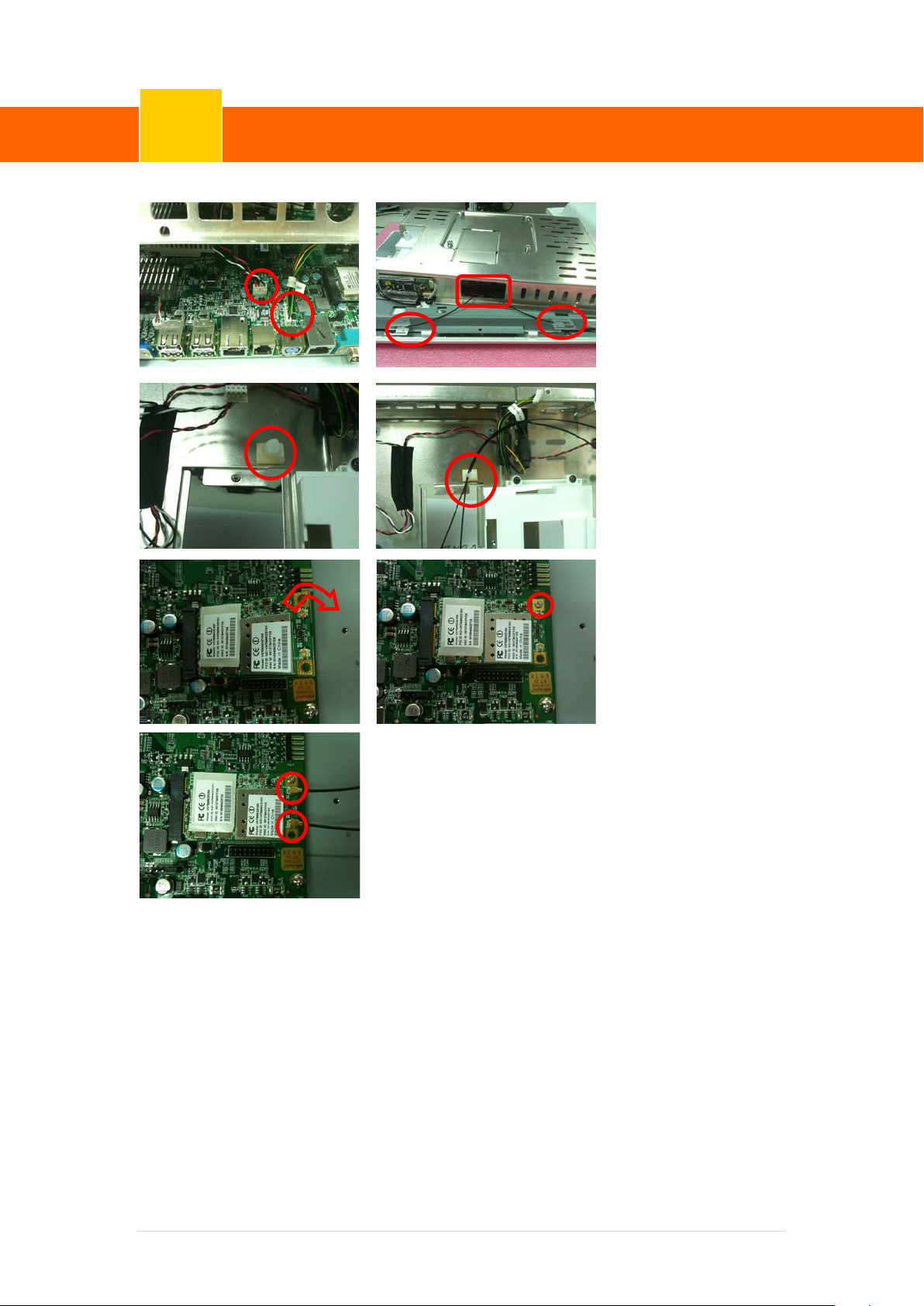
9
Version: 1.0
9. Disconnect the 2 cable
10. Adhere 2 pcs of aerials
(35D510576-000B) through
the red window
11. Adhere the cable clip
10
12. Arrange wires and adhere
them on the cable clip
13. Combine the WLAN card
and secure it with 1 M2
screw (64D920051-100B)
14. Connect 2 wires.
11 12
13
14
16 | 72
Page 23
ClientPOS PT8000 User Manual
Device Driver Installation
6
Version: 1.0
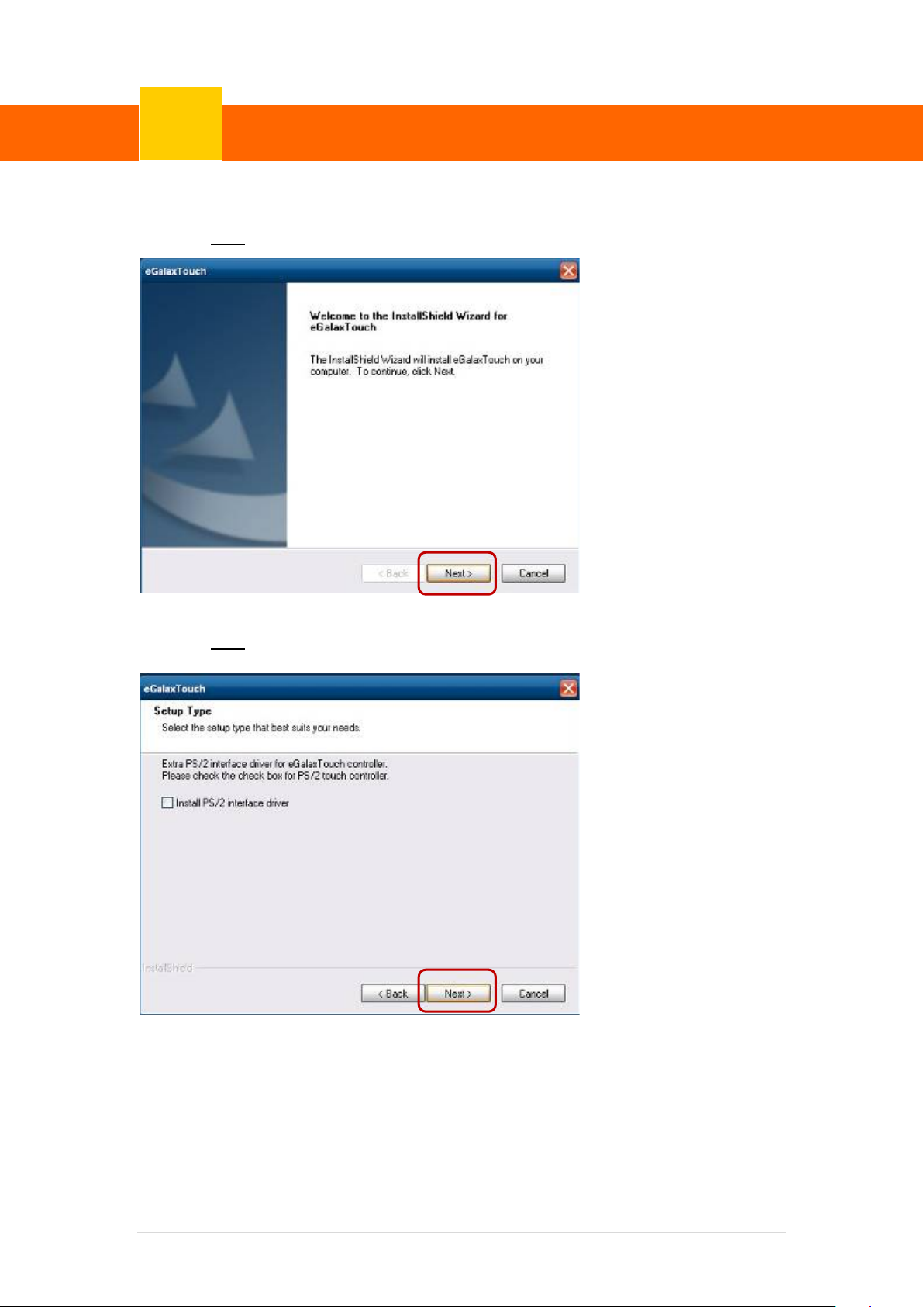
6-1 Resistive Type Touch Panel
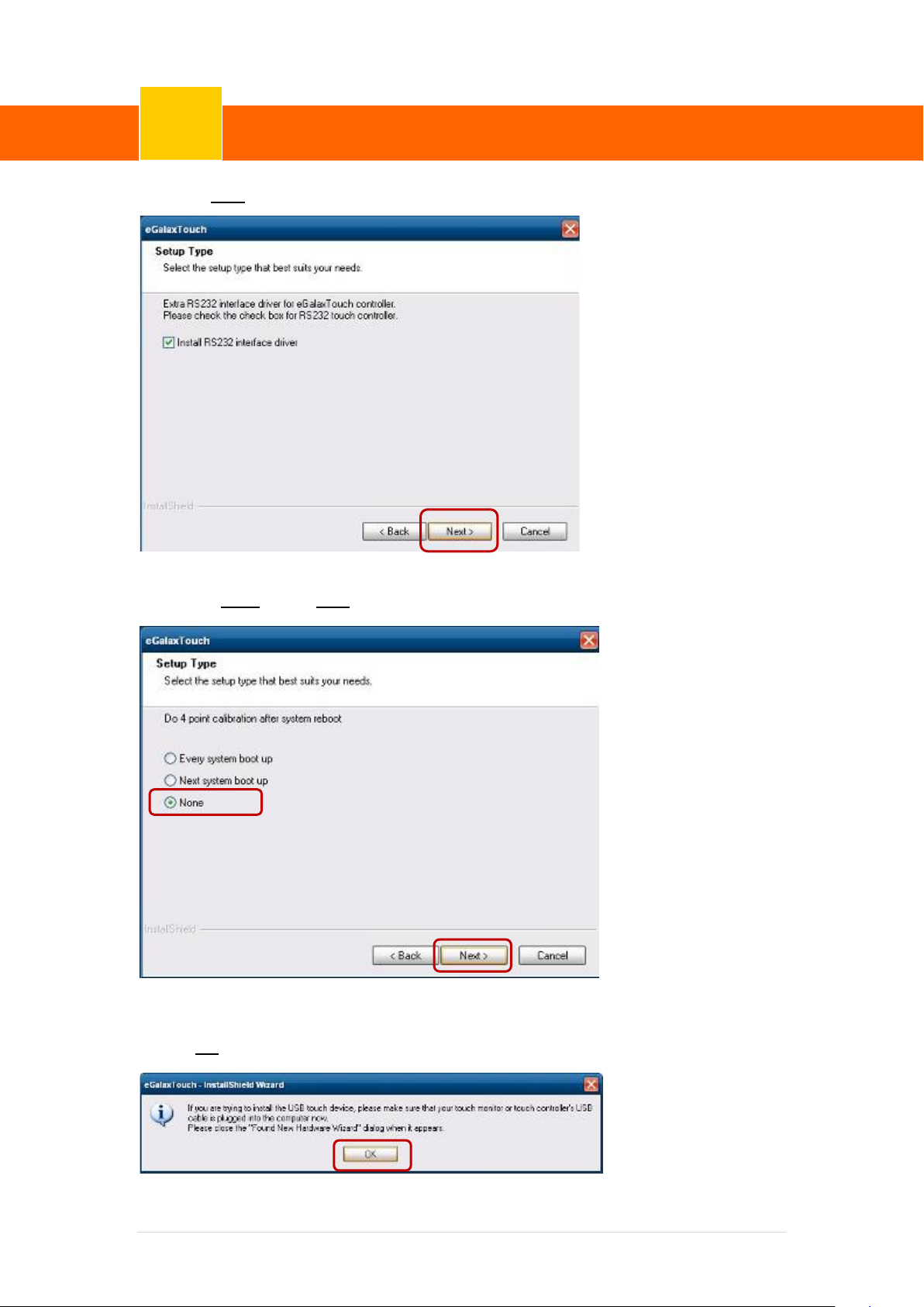
1. Click “Next”.
2. Click “Next”.
17 | 72
Page 24
ClientPOS PT8000 User Manual
Device Driver Installation
6
Version: 1.0
3. Click “Next”.
4. Select “None”, Click “Next”.
5 Click “OK”.
18 | 72
Page 25
ClientPOS PT8000 User Manual
Device Driver Installation
6
Version: 1.0
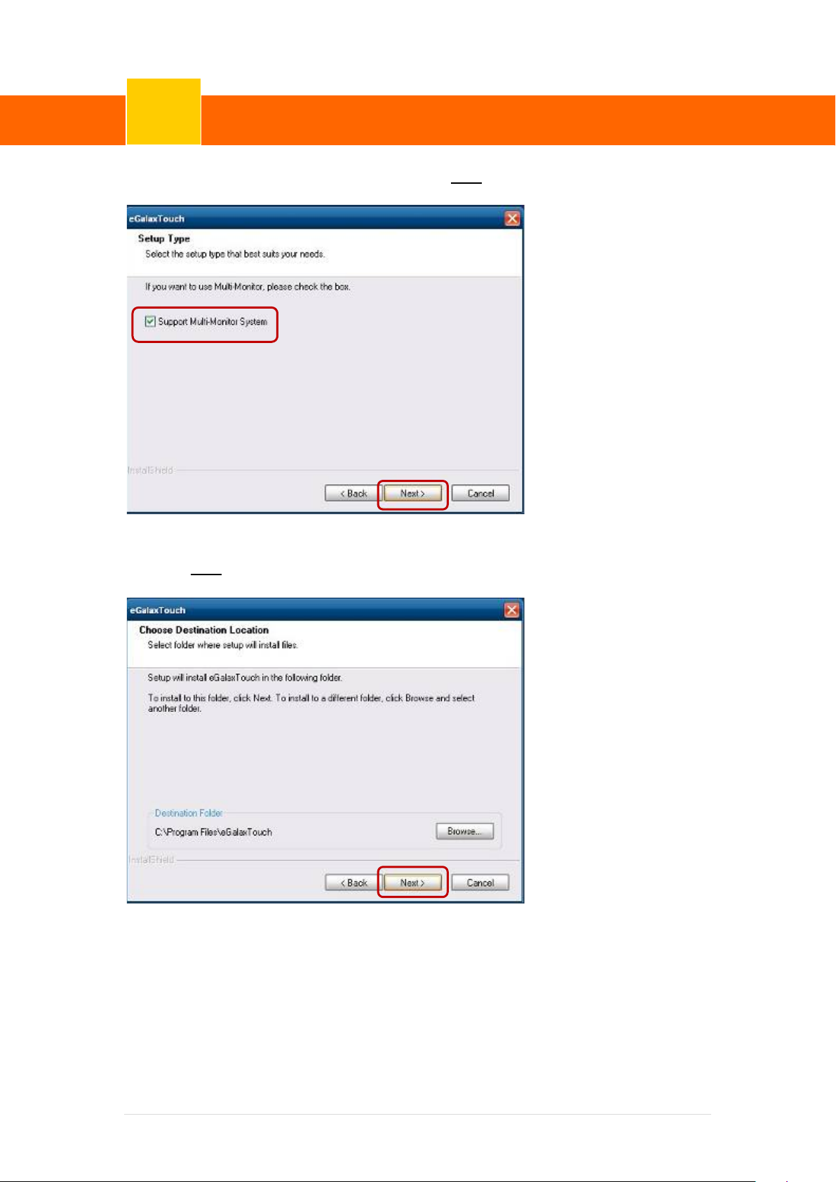
6. Select “Support Multi-Monitor System”, Click “Next”.
7. Click “Next”.
19 | 72
Page 26
ClientPOS PT8000 User Manual
Device Driver Installation
6
Version: 1.0
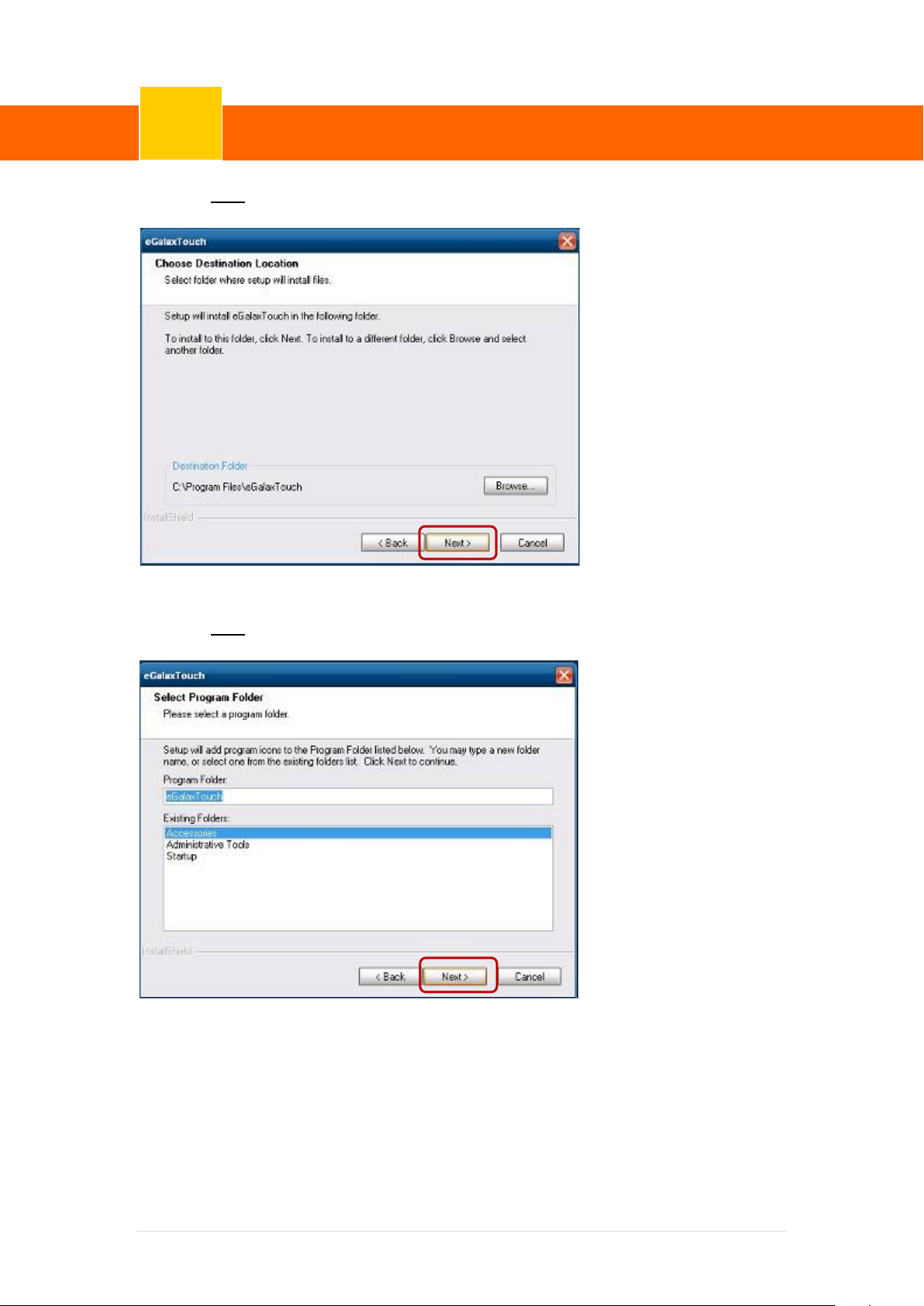
8. Click “Next”.
9. Click “Next”.
20 | 72
Page 27
ClientPOS PT8000 User Manual
Device Driver Installation
6
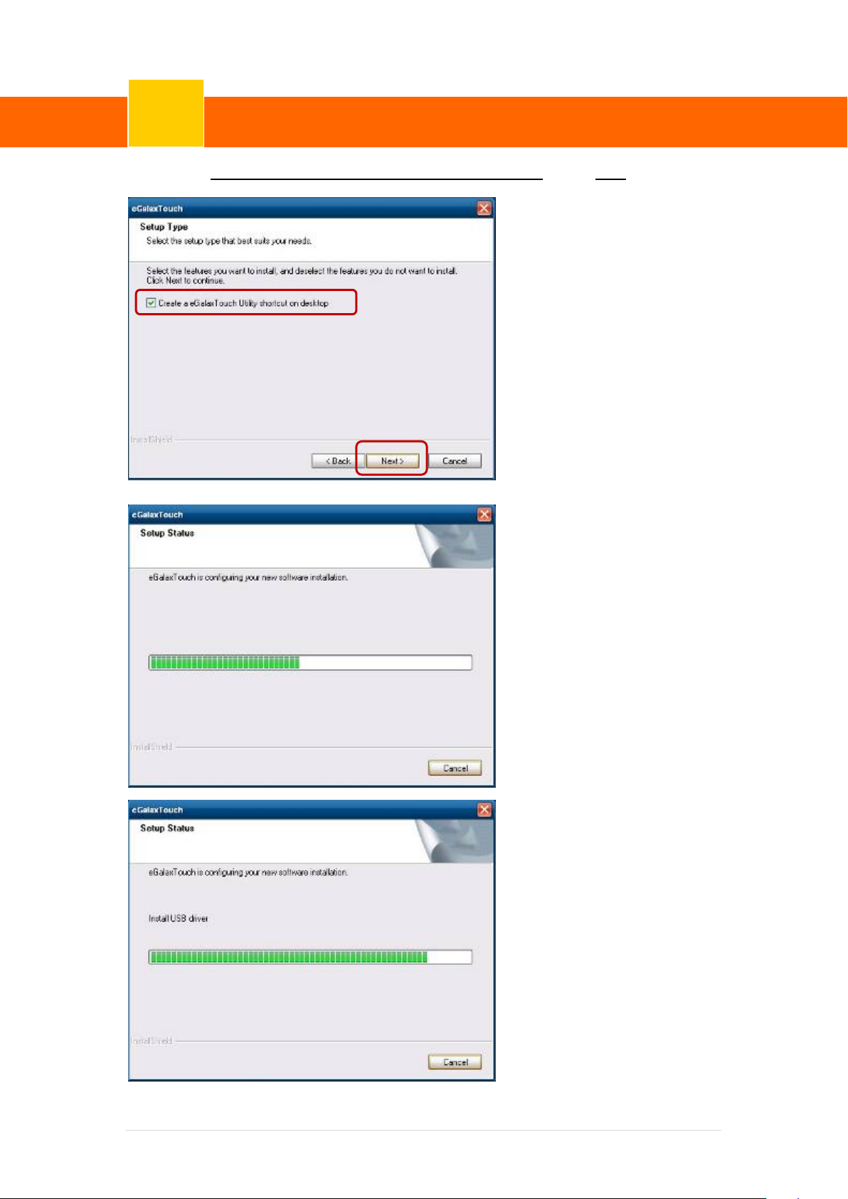
10. Select “Create a eGalaxTouch Utility shortcut on desktop”, Click “Next”.
Version: 1.0
21 | 72
Page 28
ClientPOS PT8000 User Manual
Device Driver Installation
6
Version: 1.0
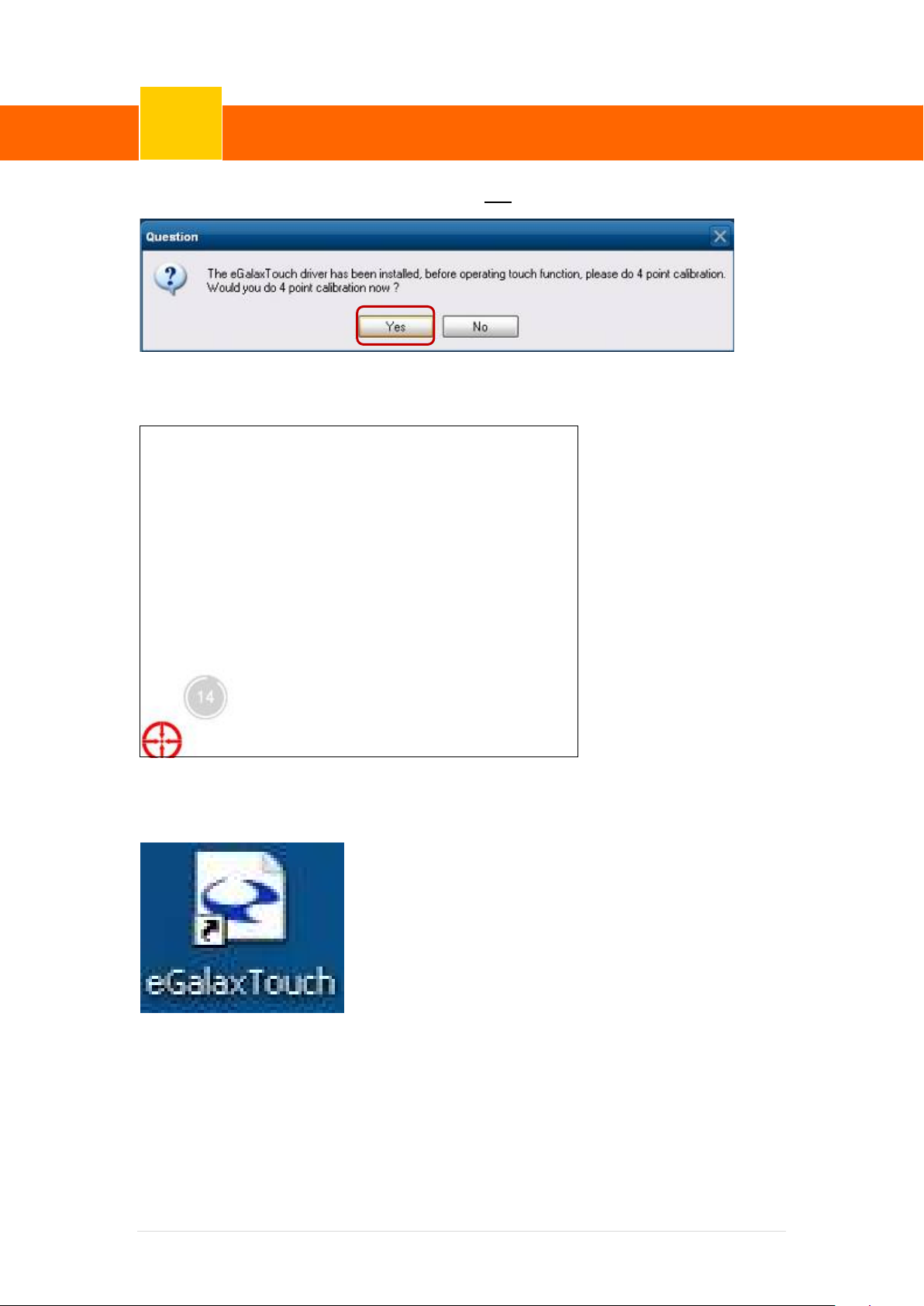
11. Would you do 4 point calibration now? Click “Yes”.
12. Do 4 points aligrment to match display.
13. Calibration utility.
22 | 72
Page 29

ClientPOS PT8000 User Manual
Device Driver Installation
6
Version: 1.0
6-2 MagStripe Card Reader Configuration Utility
The MagStripe Card Reader Configurati on Ut il i ty is used to set up the output format of HID
MSR
Installation
Below steps guide you how to install the Utility program
Insert the setup CD
Run the HID_MSR_PSW00003_V2_0_0.exe setup file that is located in the Software
folder of CD.
Follow the wizard to complete the installation.
Launching Program
Below steps guide you how to load the Utility program.
From Start/Programs, click HID_MSR2 folder
Click MagStripe Card Reader Configuration Utili ty to launch the program.
23 | 72
Page 30
ClientPOS PT8000 User Manual
Device Driver Installation
6
Version: 1.0
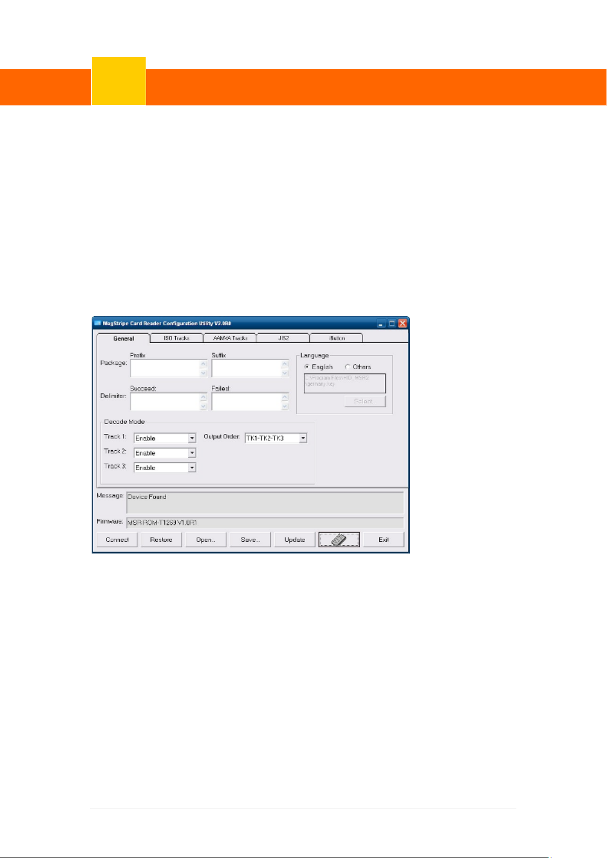
The utility program will detect the connected reader. If detected, all the input text boxes
will be enabled.
If the reader has not bee n conne cted t o PC yet , pl ease co nnect the read er a nd t hen click
Refresh to get connected.
Configuration
Below is the main window of Utility program.
For the settings, there are:
Language: The language defines the code positions of the keyboard. Each language
should use its own settings. Wrong language s elected will cause the wrong character
displayed.
Prefix/Suffix: Defines the data string which y ou would like to append in front or end of
the MSR data string.
Error Message: Indicates whi ch track number cause the error.
Delimiter: Indicates the swipe result.
24 | 72
Page 31

ClientPOS PT8000 User Manual
Device Driver Installation
6
PR2
Version: 1.0
ISO: Define start and end s entinel character.
Decode Mode: Determines the way of outputting the three tracks data.
Shown below is the data structure of the out put string for MSR.
PP PR1 SS1
TK1
ES1 SU1
SS2
PP: Prefix for package.
PR1: Prefix for track 1.
SS1: Start sentinel for track 1.
TK1: Data for track 1, if error happens,
using Error Message instead.
ES1: End sentinel for track 1.
SU1: Suffix for track 1.
PR2: Prefix for track 2.
SS2: Start sentinel for track 2.
TK2: Data for track 2, if error happens,
ES2 SU2 PR3 SS3
TK2
ES3 SU3 SU DM
TK3
ES2: End sentinel for track 2.
SU2: Suffix for track 2.
PR3: Prefix for track 3.
SS3: Start sentinel for track 3.
TK3: Data for track 3, if error happens,
using Error Message instead..
ES3: End sentinel for track 3.
SU3: Suffix for track 3.
SU: Suffix for package.
DM: Delimiter for the swi pe result.
using Error Message instead.
Prefix/Suffix
In default, the prefix and suffix settings are all keep blank. There are 4 kinds of prefix and suffix
to be defined, which are:
Package: For the pref ix st ring, i t is appended i n the f ront of the whole MS R data. For the
suffix, it is appended in the end of the whole MS R data. In most case, the suffix for package is
always to be the “Enter” or “Tab” chara cter. T he m ax dat a len gth of the pr efi x an d suff ix for t he
25 | 72
Page 32

ClientPOS PT8000 User Manual
Device Driver Installation
6
Version: 1.0
package can be up to 127.
TK1: For the prefix st ring, it is appended in the front of the start sentinel of track 2. For
the suffix, it is appended in the end of the end sentinel of track 2. The max data length of the
prefix and suffix for the TK1 can be up to 127.
TK2: For the prefix st ring, it is appended in the front of the start sentinel of track 2. For
the suffix, it is appended in the end of the end sentinel of track 2. The max data length of the
prefix and suffix for the TK1 can be up to 127.
TK3: For the prefix st ring, it is appended in the front of the start sentinel of track 3. For
the suffix, it is appended in the end of the end sentinel of track 3. The max data length of the
prefix and suffix for the TK1 can be up to 127.
ISO
This group defines the start and end sentinel for each track. The sentinel is always used to
extract the track data from the whole MSR data string. The data length for each sentinel is
fixed to one character. Because there is ISO st andard that defining the start and end sentinel
for the three tracks. For the compatible reason, pl ease do not modify the default value if
possible.
Decode Mode
For this group, it contains two kinds of settings, which are:
Track Data Filtering: Determine which track to be, not to be output or needed to be
output.
Switch Output Order: Change the output order of track 1 ~ 3.
26 | 72
Page 33
ClientPOS PT8000 User Manual
Device Driver Installation
6
Version: 1.0
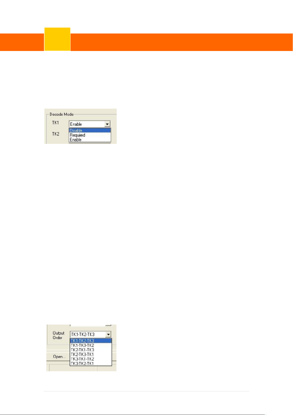
Track Data Filtering
Shown below is the filter setting for track 1. T hi s provides a fool-proofing method in case of
receiving unwanted or uncompleted track data.
These three filter settings are:
Enable: If selected, the data of sp ecified track will be p ackaged in t he MS R data s tring. I f
the specified track data is not decoded, it will leave blank in the MSR data string.
Required: If selected, which means the output MSR data string must contain the
specified track data. If the specified track data i s not decoded, even MSR data string
contains other track data, it will still not to be output .
Disable: If selected, the data of specified track will not be packaged in the MSR data
string. No matter it is decoded or not.
Switch Output Order
Show below is the selection of the three track data output order (sequence). The default order
is Track 1–Track 2–Track 3.
27 | 72
Page 34

ClientPOS PT8000 User Manual
Device Driver Installation
6
There 6 orders allow to be selected. Please select one to fit your application needs.
Version: 1.0
Update Settings
Once complete the settings, click Update to update the settings to connected HID MSR
reader.
Save Settings
To save the settings to a file, click Save; specify the file name and location to be saved.
Open Settings
To load pre-saved settings, click Open, specify the settings file, and then click OK to load into
program.
Restore MSR Reader Settings
To load restore settings of connected MSR reader, click Restore ES2: End sentinel for track.
28 | 72
Page 35
ClientPOS PT8000 User Manual
Device Driver Installation
6
Version: 1.0
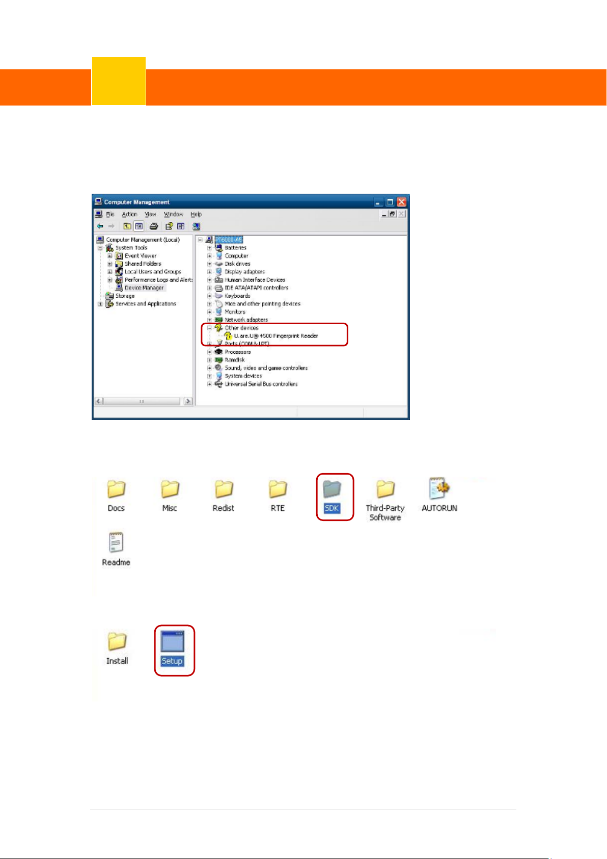
6-3 Fingerprint Reader
1. Check Fingerprint reader be detected by “Device m anager “
2. Select SDK folder.
3. Run Setup.exe.
29 | 72
Page 36
ClientPOS PT8000 User Manual
Device Driver Installation
6
Version: 1.0
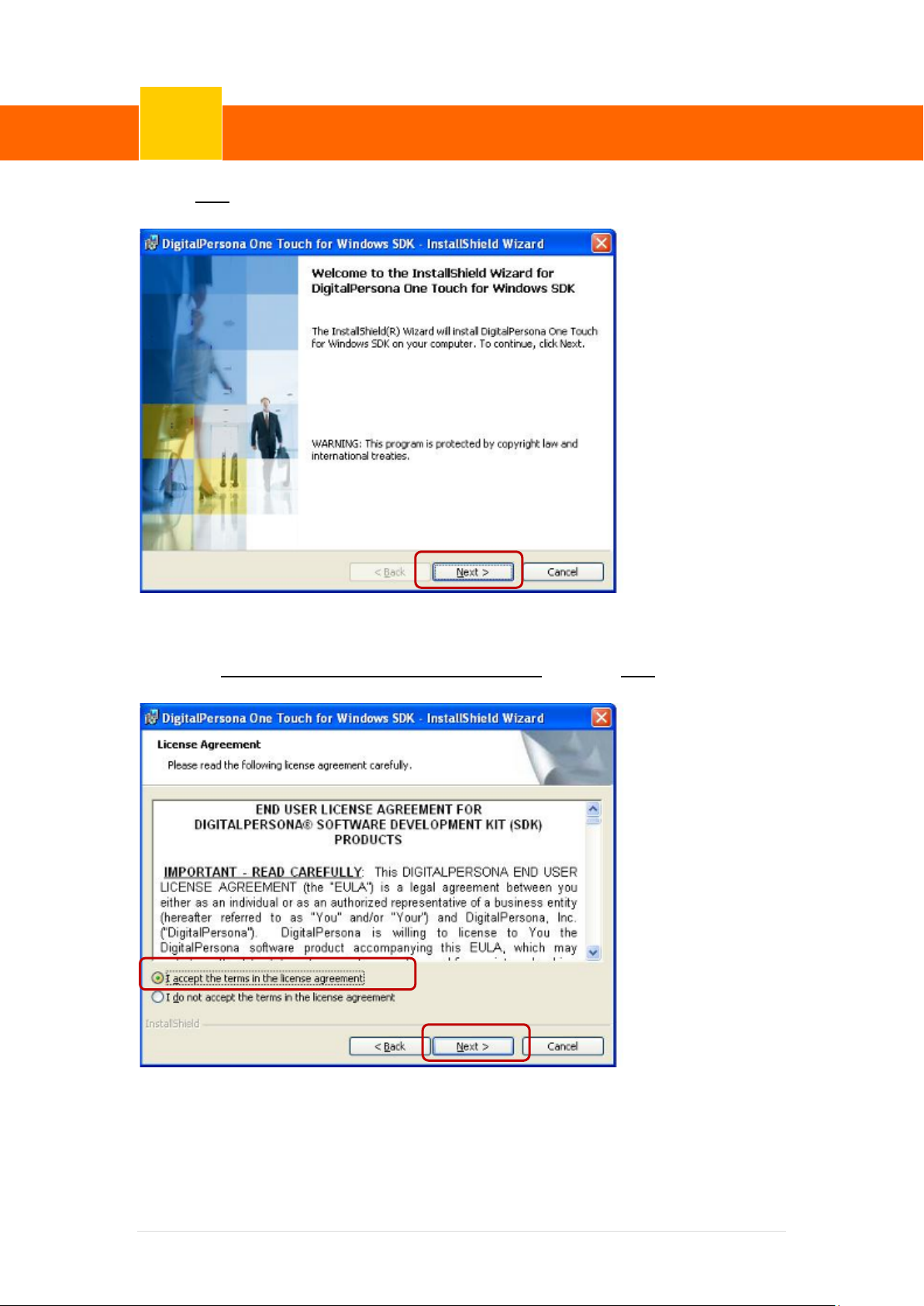
4.Click “Next”.
5. Select “ I accept the terms in the license agreement” and click “Next”.
30 | 72
Page 37
ClientPOS PT8000 User Manual
Device Driver Installation
6
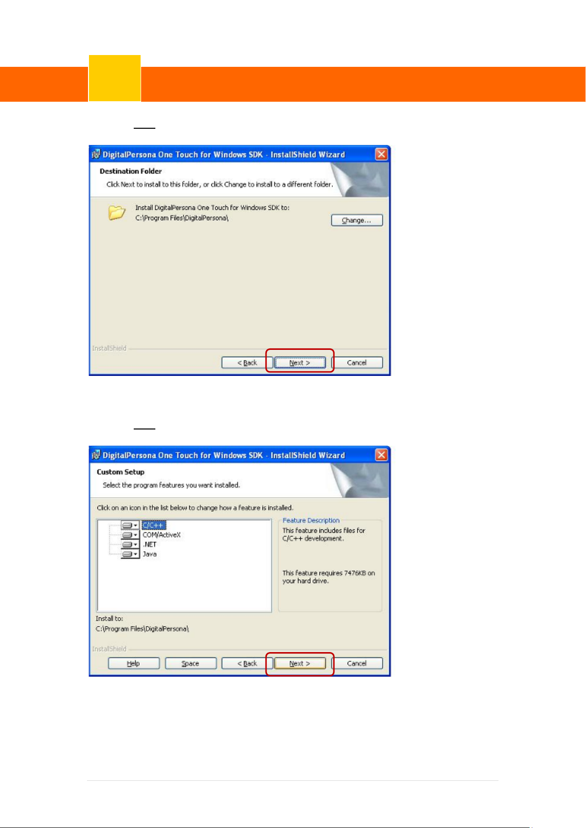
Version: 1.0
6. Click “Next”.
7. Click “Next”.
31 | 72
Page 38
ClientPOS PT8000 User Manual
Device Driver Installation
6
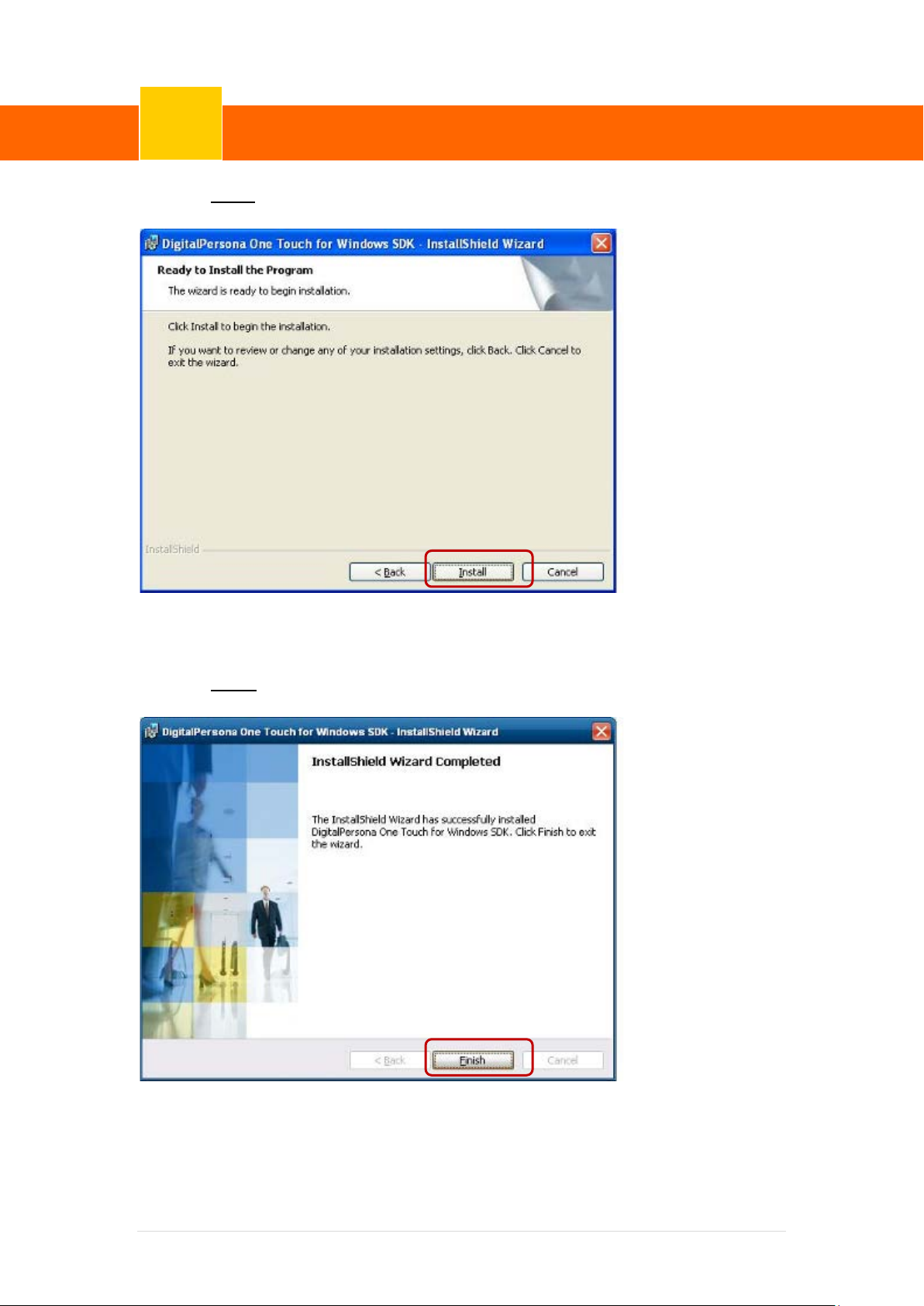
Version: 1.0
8. Click “Install”.
9. Click “Finish”.
32 | 72
Page 39

ClientPOS PT8000 User Manual
Device Driver Installation
6
Version: 1.0
10. Restart systems.
11. Check Fingerprint reader in Device Manager.
33 | 72
Page 40
ClientPOS PT8000 User Manual
Device Driver Installation
6
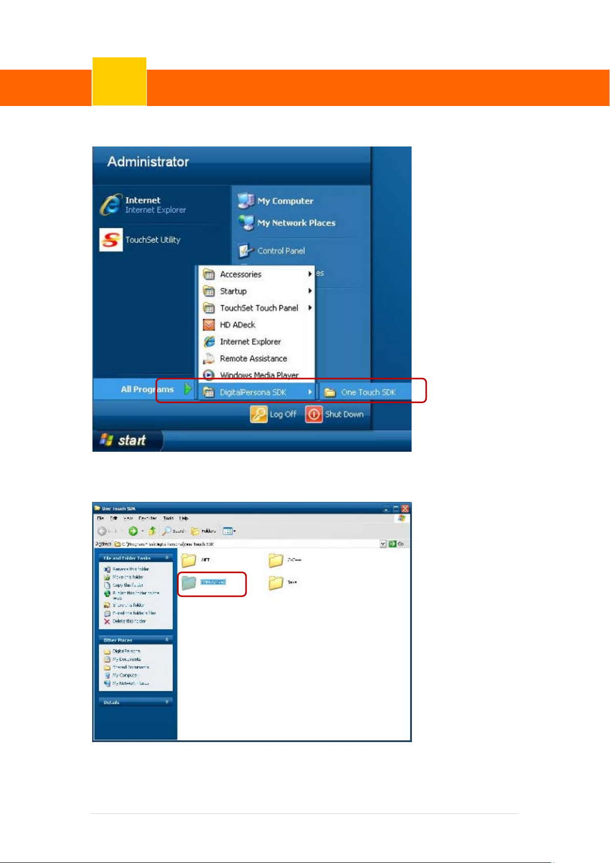
Version: 1.0
12. Launch Fingerprint reader from start menu
13. Select “COM-ActiveX”
34 | 72
Page 41
ClientPOS PT8000 User Manual
Device Driver Installation
6
Version: 1.0
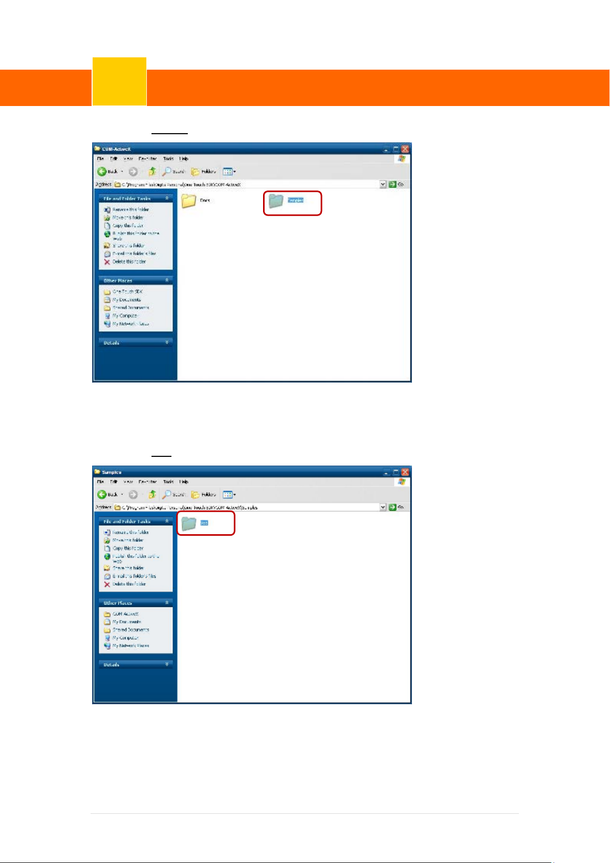
14. Select “Sample”
15. Select ”VB6’.
35 | 72
Page 42
ClientPOS PT8000 User Manual
Device Driver Installation
6
Version: 1.0
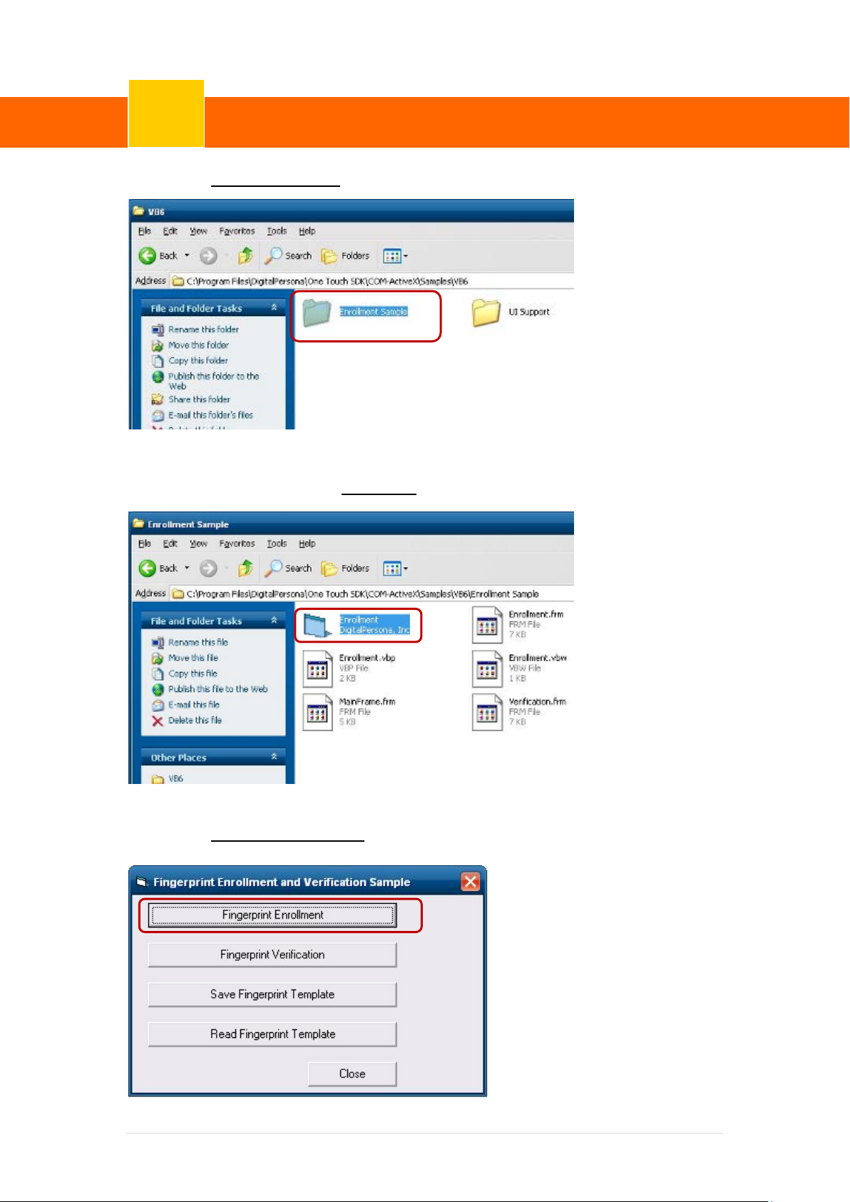
16. Select “Enrollment Sample”.
17. Enroll the fingerprint by the “Enrollment“
18. Select “Fingerprint Enrollment”
36 | 72
Page 43
ClientPOS PT8000 User Manual
Device Driver Installation
6
Version: 1.0
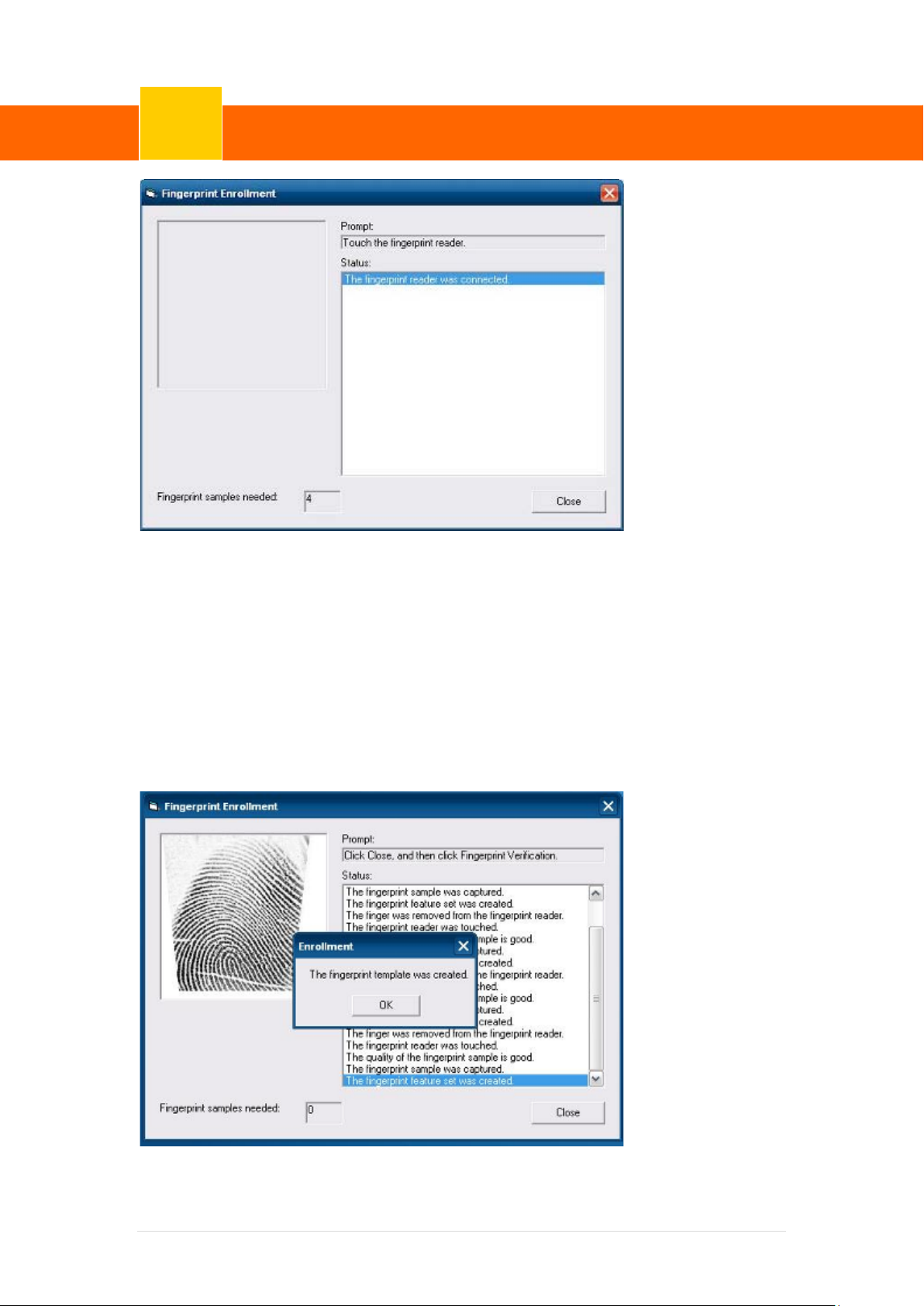
19. Put your finger on fingerprint reader and follow the direction to enroller your fingerprint, it
need scan your fingerprint 4 times
20. After enroller finish it will popup a dialog box
37 | 72
Page 44
ClientPOS PT8000 User Manual
Device Driver Installation
6
Version: 1.0
6-4 RFID
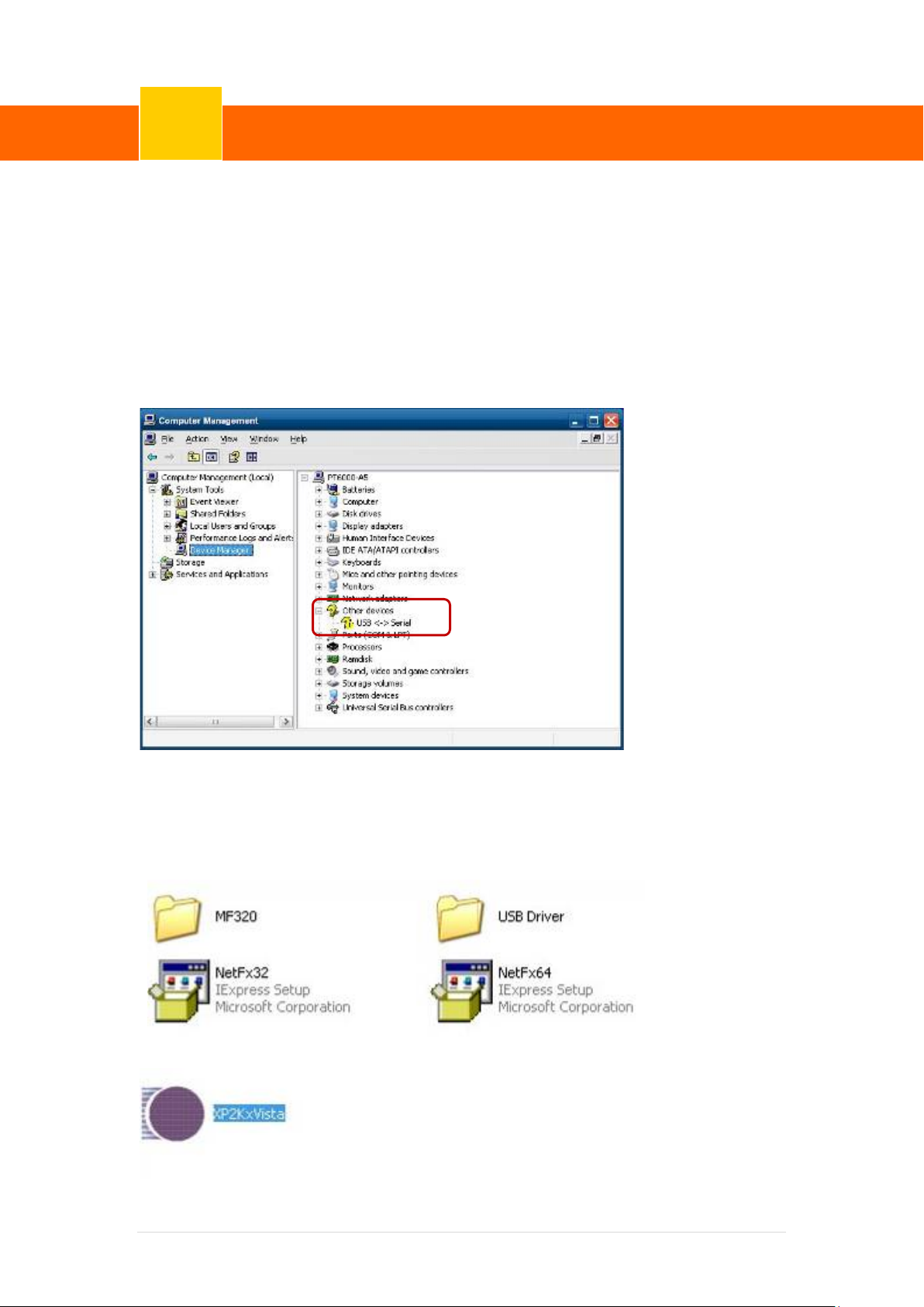
1. Install (Operating System: Microsoft Windows POSReady 2009)
1.1 Check the Device Manager to verify the statu s of RFID reader.
Computer Management -> Device Manager -> Other devices (The device wil l show a
question mark if the installation i s not done properly.)
1.2 Install RFID driver,file name:XP2KxVista.exe
2-1 Path:\USB Driver\ XP2KxVista.exe
38 | 72
Page 45
ClientPOS PT8000 User Manual
Device Driver Installation
6
Version: 1.0
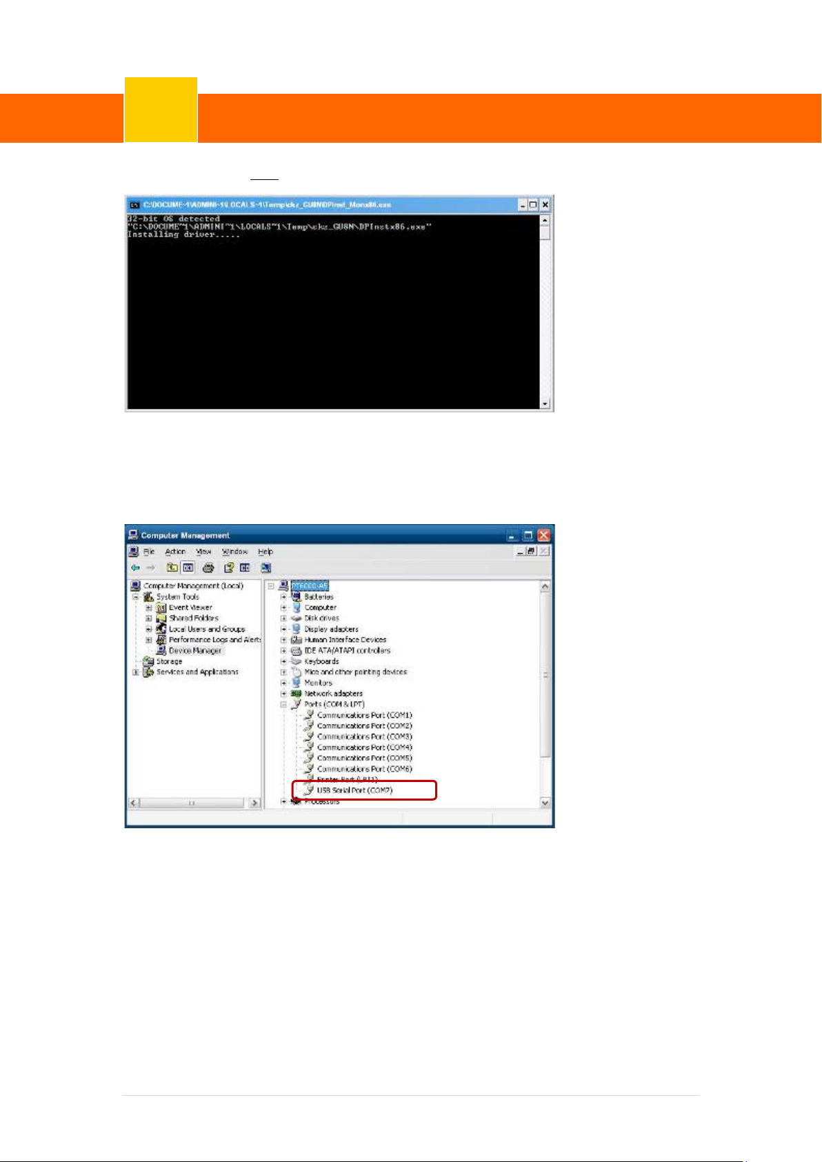
1.2.1 After clicking Next, A pop up console window appears as below.
1.2.2 Check the Device Manager to verify the status of RFID reader.
Computer Management -> Device Manager -> Ports (COM & LPT)
39 | 72
Page 46
ClientPOS PT8000 User Manual
Device Driver Installation
6
Version: 1.0
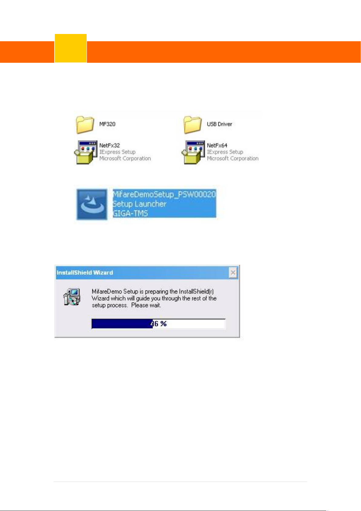
1.3 install RFID utility
MifareDemoSetup_PSW00020.exe
3-1 Path:\MF320\MifareDemoSetup_PSW00020.exe
1.3.1 InstallShield Wizard will be activ ated.
40 | 72
Page 47
ClientPOS PT8000 User Manual
Device Driver Installation
6
Version: 1.0
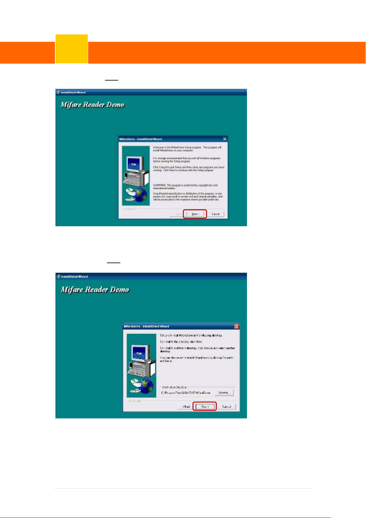
1.3.2 Click “Next”.
1.3.3 Click “Next”.
41 | 72
Page 48
ClientPOS PT8000 User Manual
Device Driver Installation
6
Version: 1.0
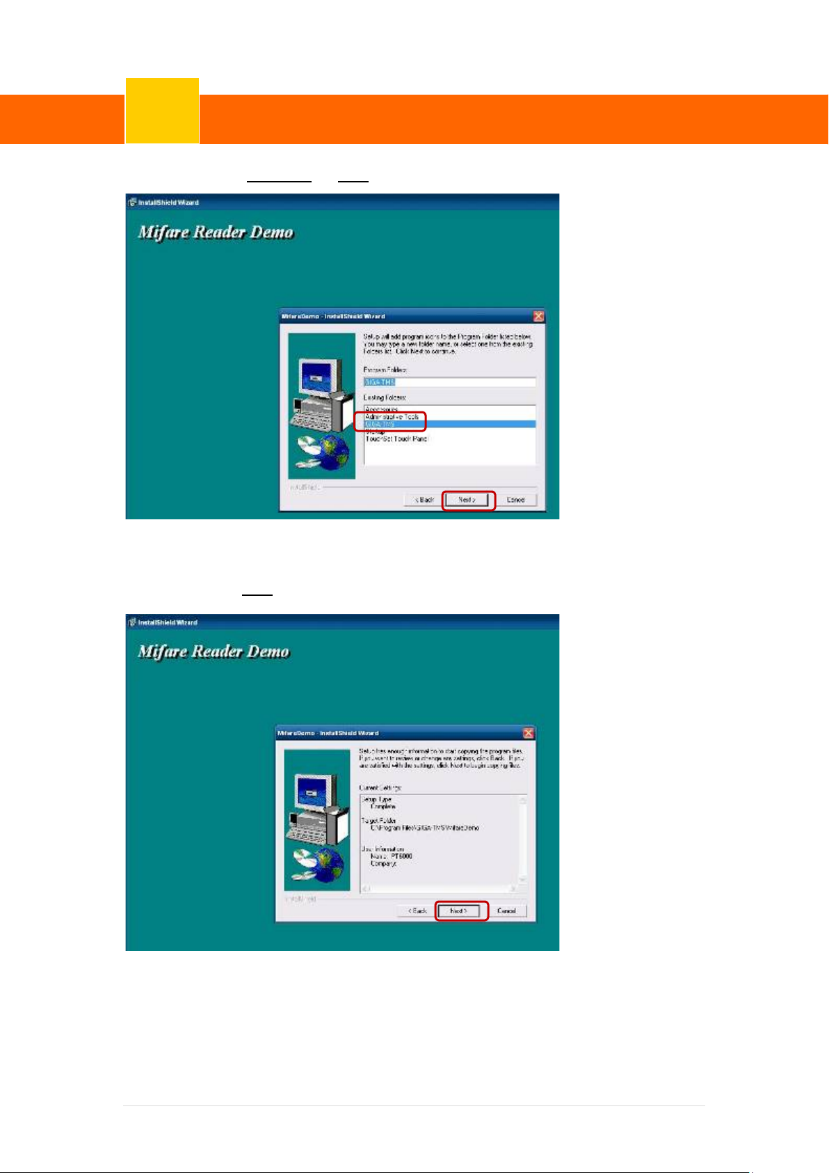
1.3.4 Click “Giga-TMS” & “Next”.
1.3.5 Click “Next”.
42 | 72
Page 49
ClientPOS PT8000 User Manual
Device Driver Installation
6
Version: 1.0
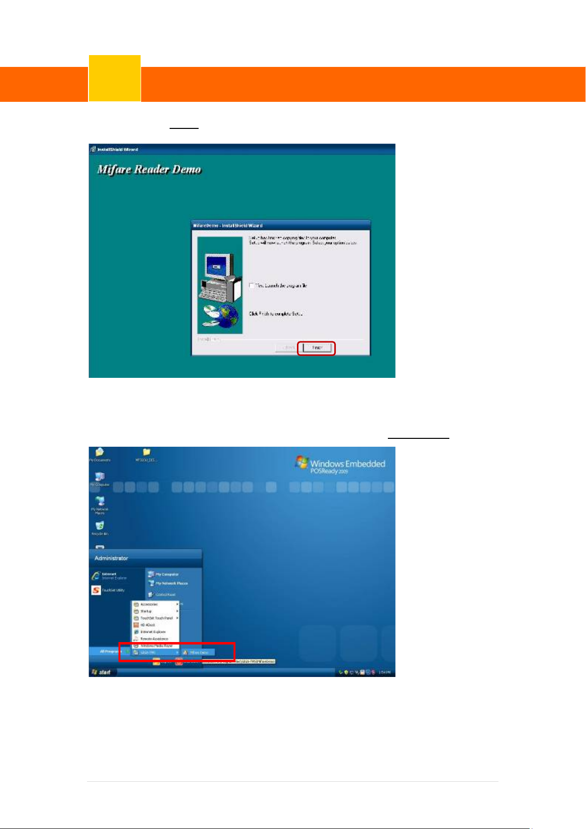
1.3.6 Click “Finish”
2. Run RFID demo program. Start -> All Programs -> GIGA-TMS -> Mifare Demo
43 | 72
Page 50
ClientPOS PT8000 User Manual
Device Driver Installation
6
Version: 1.0
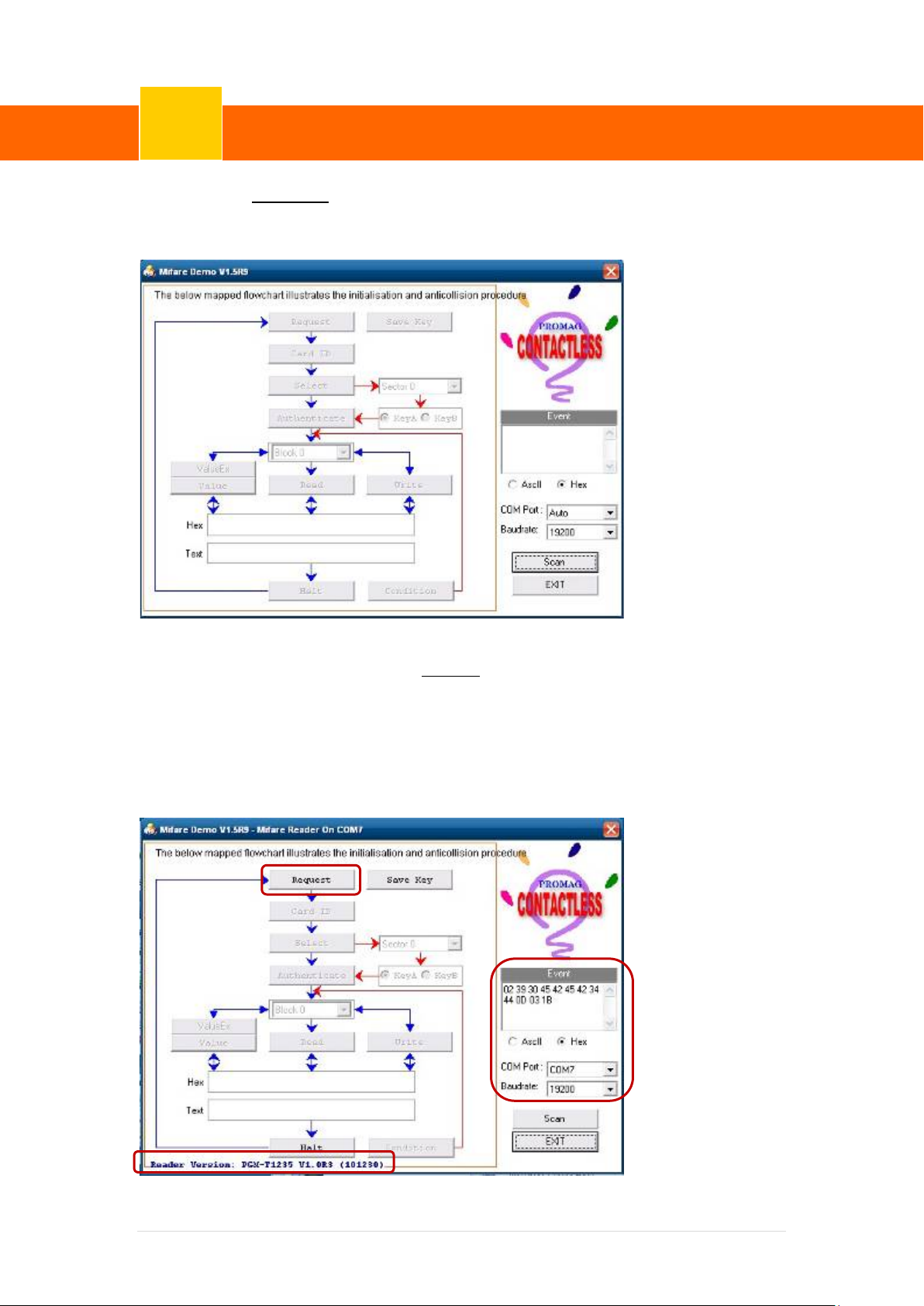
2.1 Run “Auto Scan” Demo AP will detect the RFID reader automatically.
Or select the RFID COM port
2.2 After finishing the AutoScan, Request box will be ready for the cli ck and Reader
Version will show on the position as marked. (Reader Version: PGM-T1235 V1.0R3
(101230) Place Mifare Card to the RFID reader area. Event Dialog window gets the
data from the Mifare Card.
44 | 72
Page 51
ClientPOS PT8000 User Manual
Device Driver Installation
6
Version: 1.0
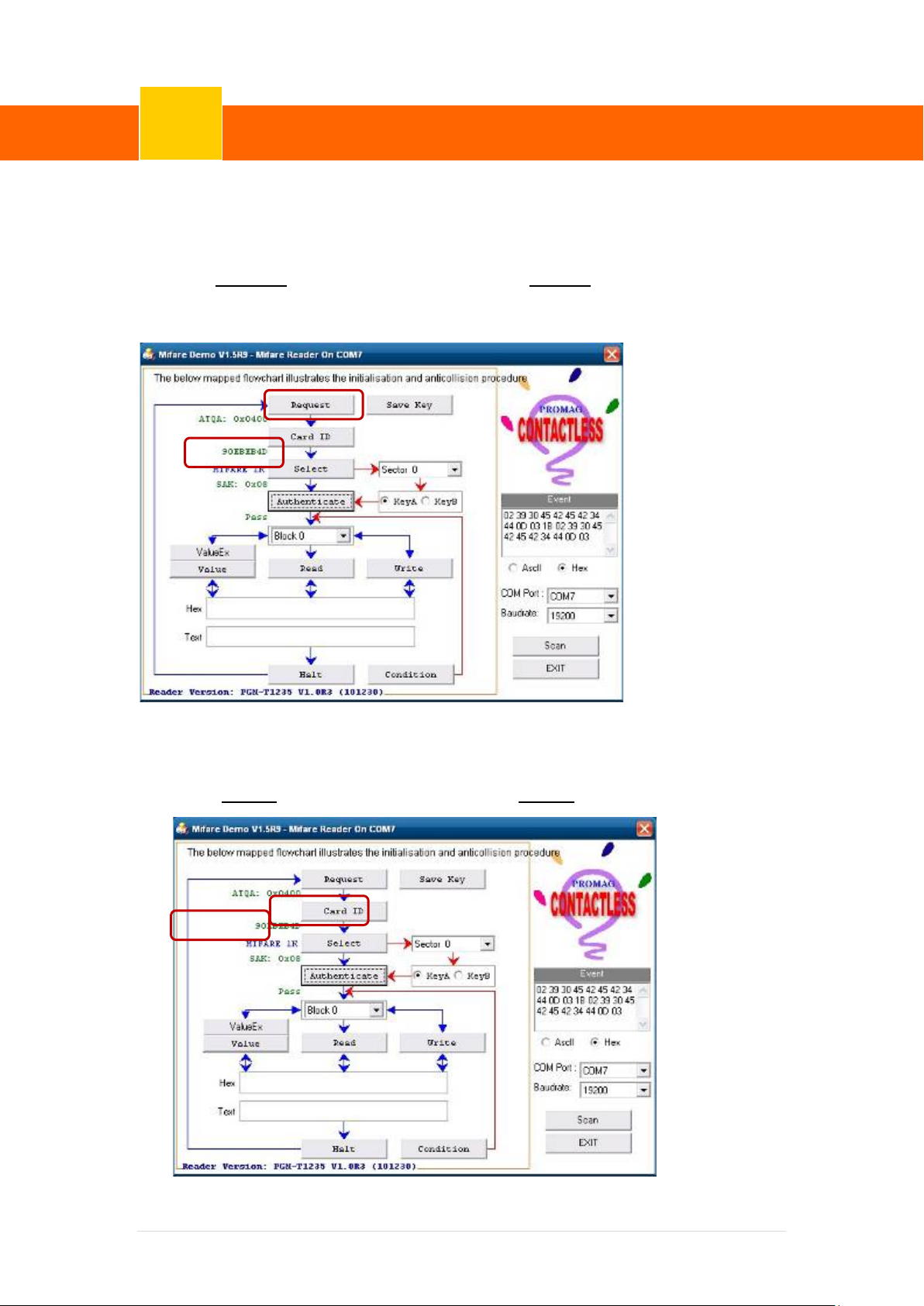
Place the RFID card on the RFID reader.
2.3 Card type will be recognized when you click “Request”.
(Your Mifare card should be placed on the RFID reader ar ea.)
2.4 Card ID will be recognized when you click “Card ID”.
45 | 72
Page 52
ClientPOS PT8000 User Manual
Device Driver Installation
6
Version: 1.0
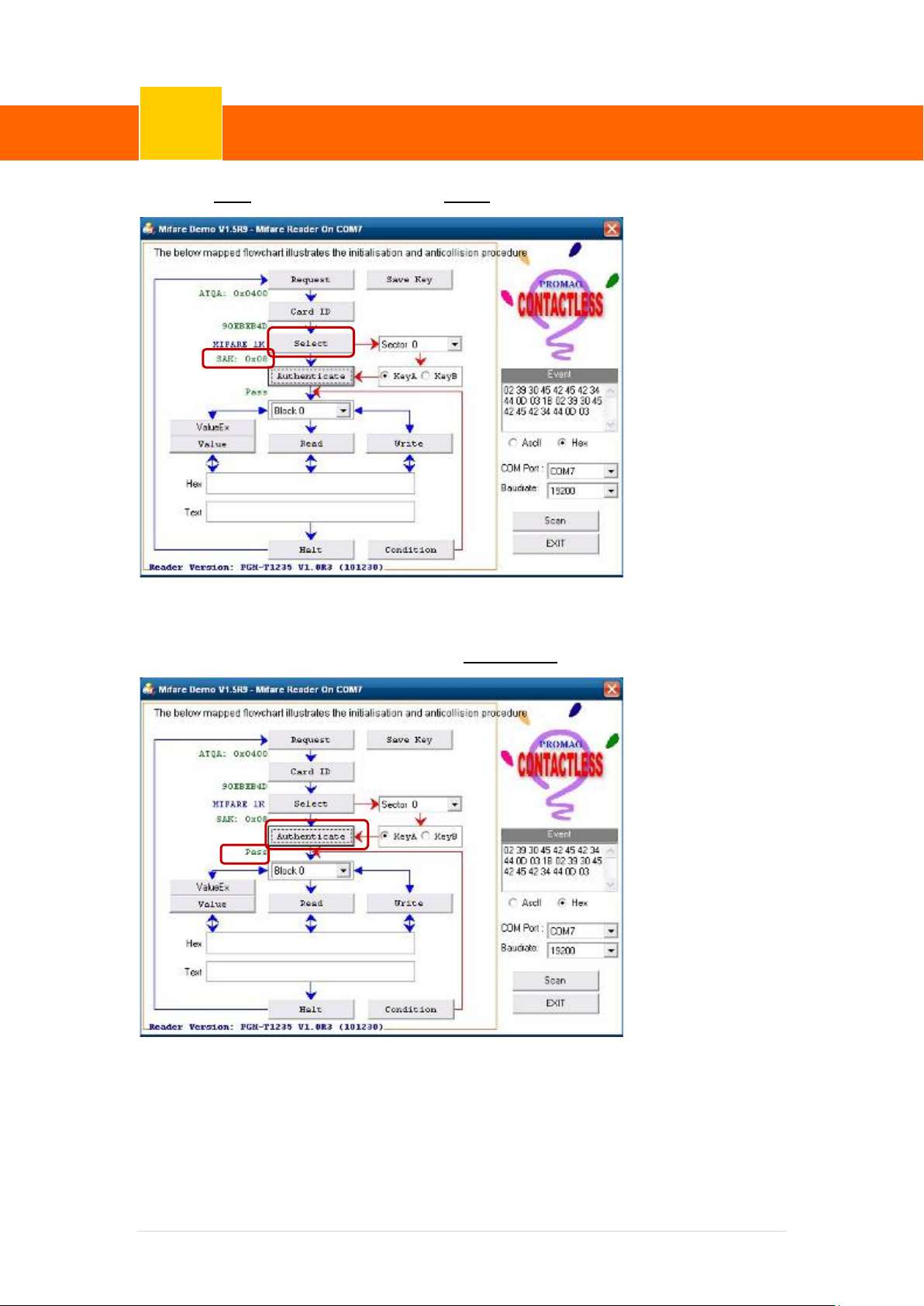
2.5 SAK will be read when you click “Select”.
2.6 The result will show when you click “Authenticate”.
46 | 72
Page 53

ClientPOS PT8000 User Manual
Device Driver Installation
6
CD5220, EMAX, LOGIC CONTROL
Italy, Spain, Norway,
Japan(Katakana), Slavonic, Russian, Greek, Czech, Lativain
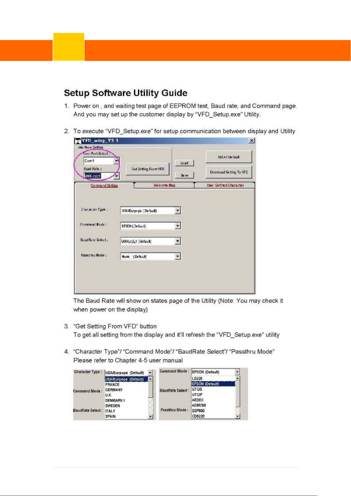
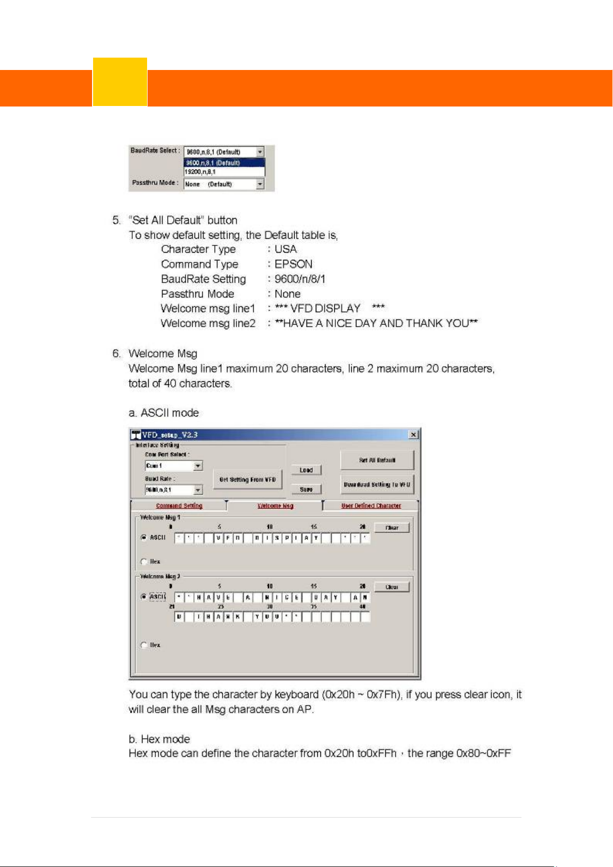
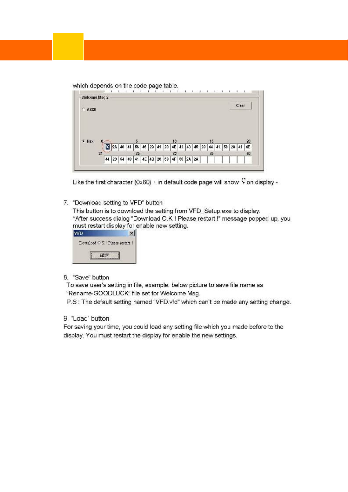
6-5 Internal VFD
Specification
Display Method Vacuum Fluorescent Display(blue-Green)
Number of Characters 40 (20 Columns X 2 Lines)
Brightness 500 ~ 1000 cd/m2
Character Font 5X7 Doc Matrix
General
Character T ype 95 Alphanumeric, 32 International Characters
Character Size 6.75(H) X 3.75(W)mm
Doc Size (X x Y) 0.55 x 0.75 mm
Version: 1.0
Commands Mode
Language Support
Interface
Connection
Reliability
Power
Safety
Download Characters 9 Characters
LD220, EPSON POS D101(default), AEDEX, UTC/S, UTC/P, ADM788, DSP800,
USA, France, Germany, UK, Sweden, Denmark I & II,
RS-232(Serial)
Baud Rate Direct Connection 9600 or 19,200 bps
MTBF 30,000 Hours
Consumption 5-12 VDC
EMC Standards & Safety Standards FCC, CE
47 | 72
Page 54
ClientPOS PT8000 User Manual
Device Driver Installation
6
Version: 1.0
48 | 72
Page 55
ClientPOS PT8000 User Manual
Device Driver Installation
6
Version: 1.0
49 | 72
Page 56
ClientPOS PT8000 User Manual
Device Driver Installation
6
Version: 1.0
50 | 72
Page 57
ClientPOS PT8000 User Manual
Device Driver Installation
6
Version: 1.0
6-6 i-Button Reader Configuration Utility
The i-Button Reader Configuration Utility is used to set up the output format of HID MSR
Installation
Below steps guide you how to install the Utility program.
Insert the setup CD
Run the HID_MSR_PSW00003_V2_0_0.exe setup file that is located in the Software
folder of CD.
Follow the wizard to complete the installation.
Launching Program
Below steps guide you how to load the Utility program.
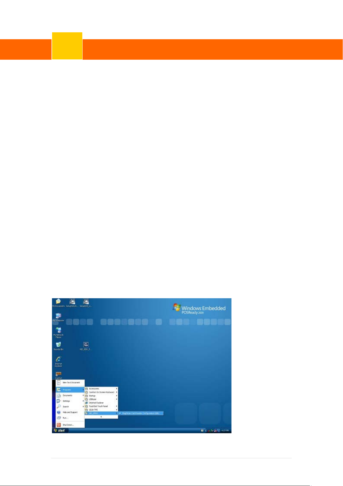
From Start/Programs, click HID_MSR2 folder
Click MagStripe Card Reader Configuration Utili ty to launch the program.
51 | 72
Page 58
ClientPOS PT8000 User Manual
Device Driver Installation
6
Version: 1.0
The utility program will detect the connected reader. If detected, all the input text boxes
will be enabled.
If the reader has not bee n conne cted t o PC yet , pl ease co nnect the read er a nd t hen click
Refresh to get connected.
Configuration
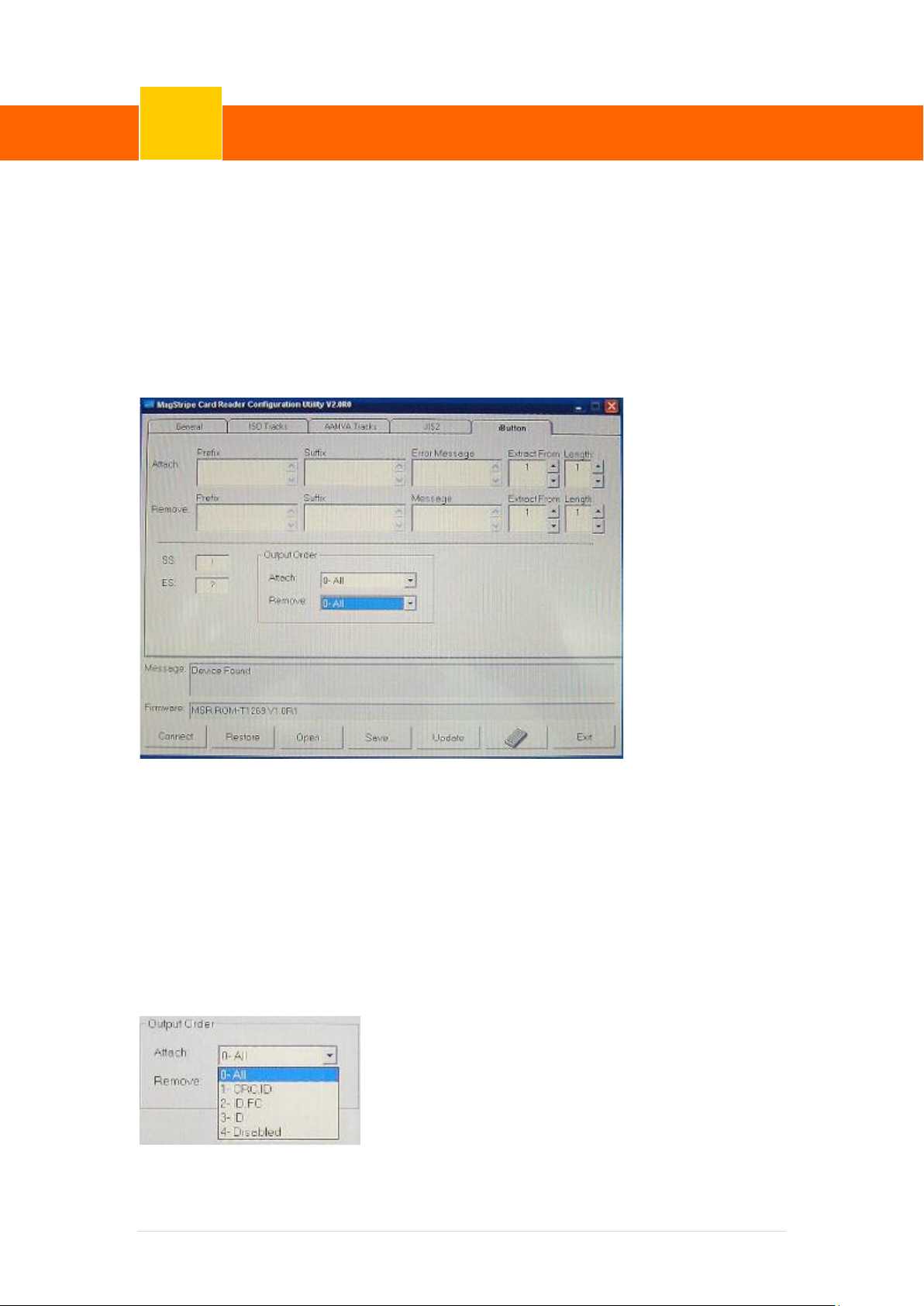
Below is the main window of i-Button Utility program.
For the settings, there are:
Prefix/Suffix: Defines the data string which y ou would like to append in front or end of
the i-Button key string.
Error Message: Indicates error m essage when i-Button key read fail.
Message: Indicates message when i-Button key read correctly
SS/ES : Define Start and End senti nel byte for the i-Button ID string
Length : i-Button ID length request from 0~16
Output order : 4 format could be select at Attach /Remove i-Button ID
52 | 72
Page 59

ClientPOS PT8000 User Manual
Device Driver Installation
6
Version: 1.0
Update Settings
Once complete the settings, click Update to update the settings to connected HID MSR
reader.
Save Settings
To save the settings to a file, click Save; specify the file name and location to be saved.
Open Settings
To load pre-saved settings, click Open, specify the settings file, and then click OK to load into
program.
Restore iButton Reader Settings
To load restore settings of connected iButton reader, click Restore ES2: End sentinel for
track.
53 | 72
Page 60
ClientPOS PT8000 User Manual
Device Driver Installation
6
Version: 1.0
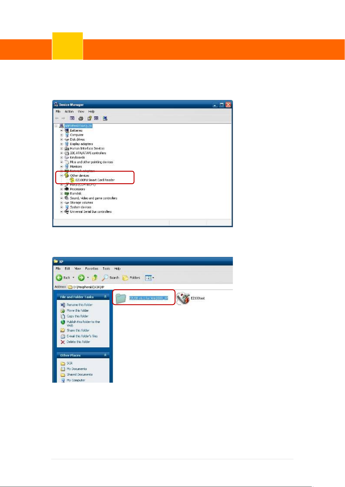
6-7 Installation and Test i ng of Smart Card Reader
1. Check smart card reader be detected by “Device m anager”.
2. Install the SCR driver.
54 | 72
Page 61
ClientPOS PT8000 User Manual
Device Driver Installation
6
Version: 1.0
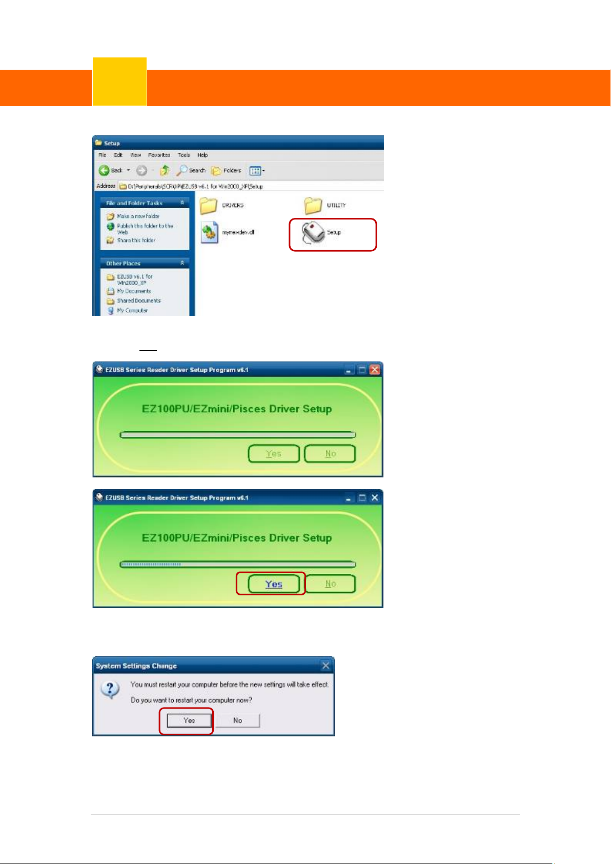
3. Run Setup.exe.
4. Click “Yes”.
5. Restart systems.
55 | 72
Page 62
ClientPOS PT8000 User Manual
Device Driver Installation
6
Version: 1.0
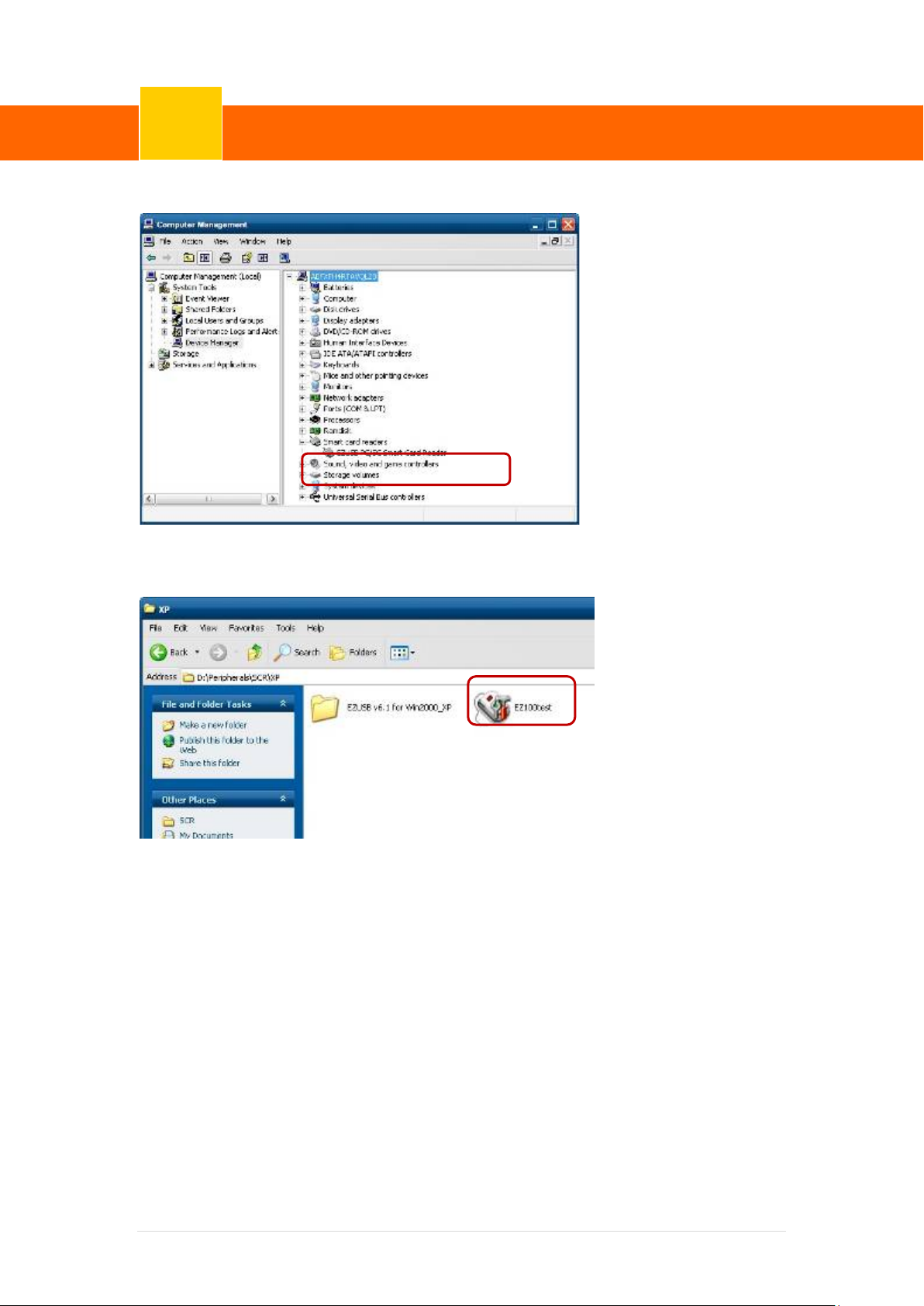
6. Check SCR reader in Device Manager.
7. Run the testing program – EZ100test.
56 | 72
Page 63
ClientPOS PT8000 User Manual
Device Driver Installation
6
Version: 1.0
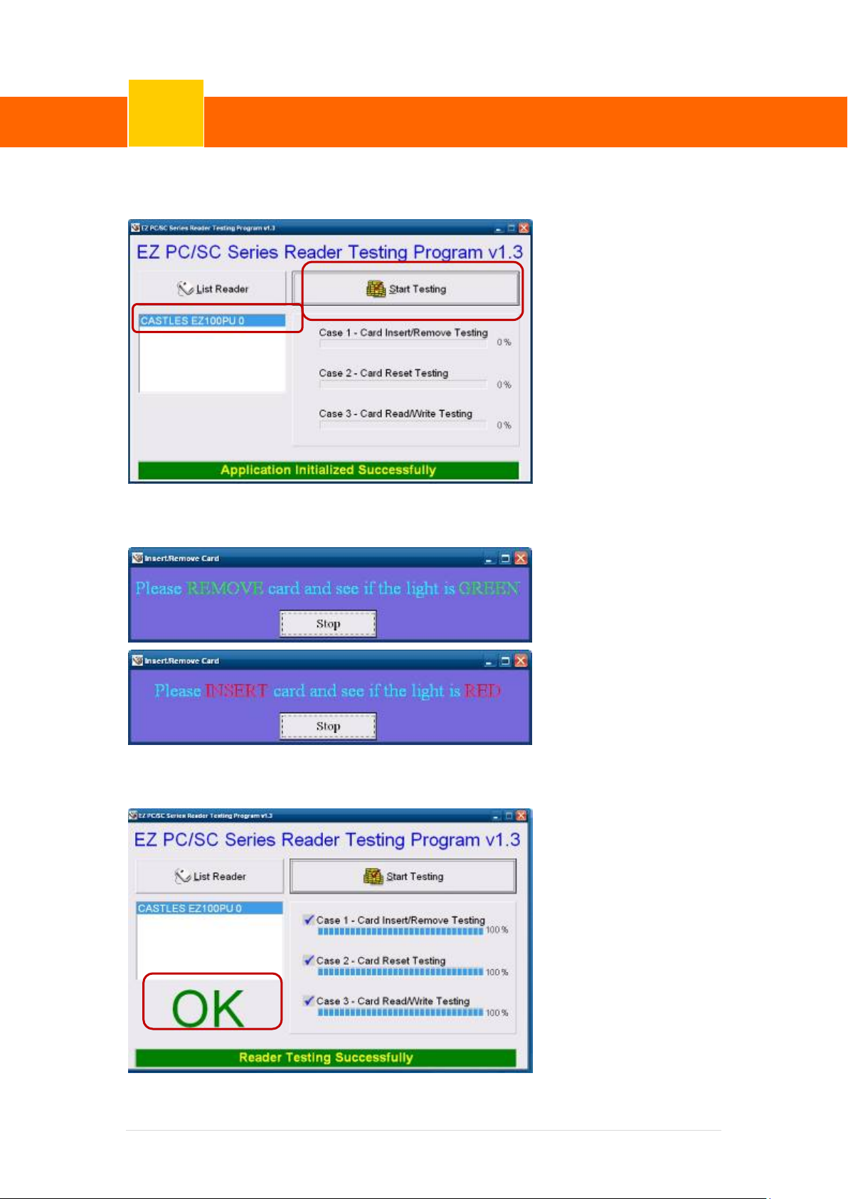
8. Conferm that SCR can be detected by the testing program, t hen run the program - the
St art Testing.
9. Follow dialog boxes displayed to remove and insert card.
10. After finishing the testing, the dialog box will show “oK”.
57 | 72
Page 64
ClientPOS PT8000 User Manual
BIOS/Utility setup
☆
Version: 1.0
7
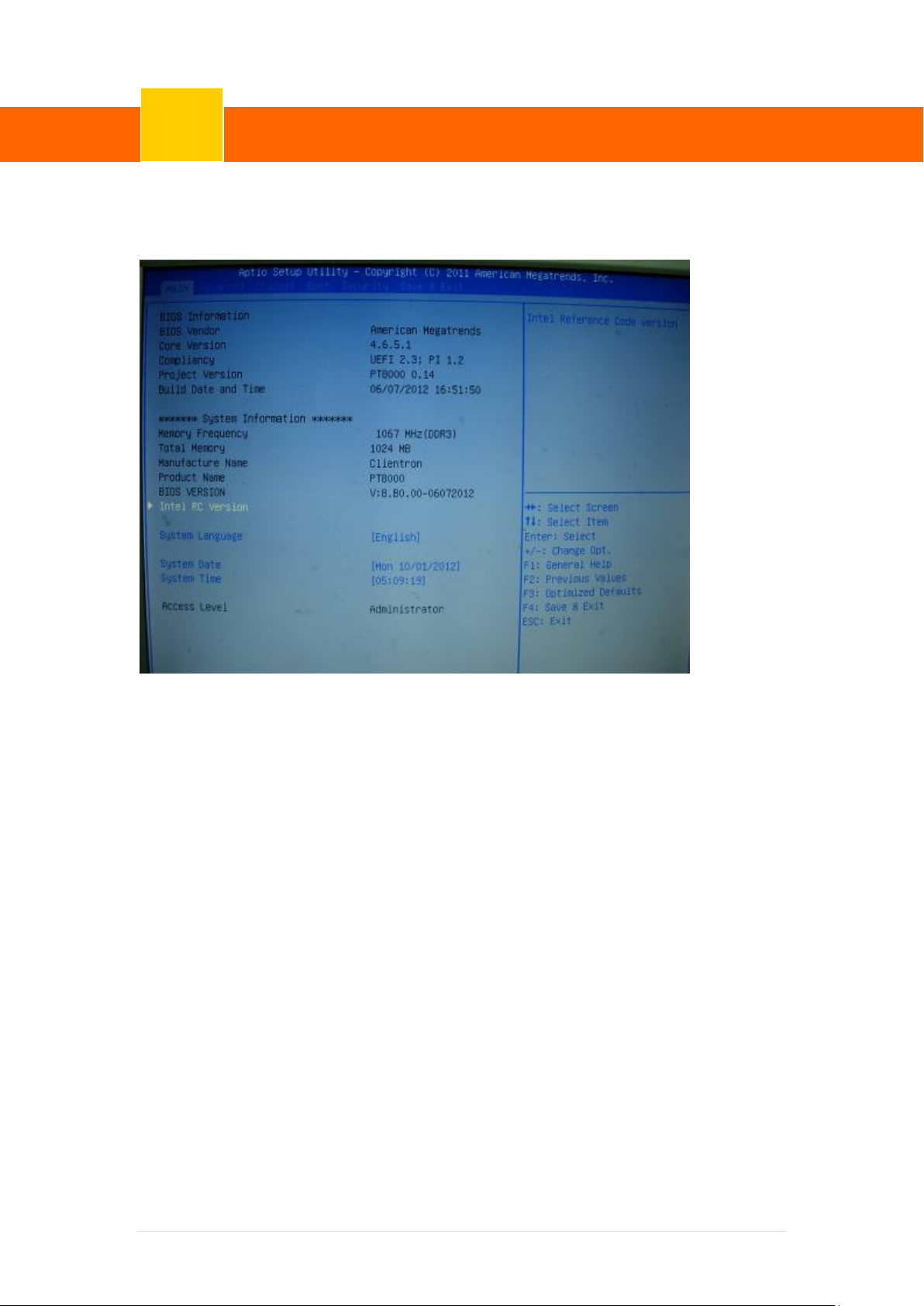
Press <DEL > / <F2> key to enter BIOS SETUP UTILITY when system boot up.
Please press <DEL > / <F2> key tenderly and slowly.
Date and Time
The Date and Time items show the current date and time on the computer. If you are running a
Windows OS, these items are automatically updated whenever you make changes to the
Windows Date and Time Properties utility .
WARNING!
Setting the wrong values in the sections belo w may cause the system to malfunction.
Make sure that the settings made are compatible with the hardware.
58 | 72
Page 65
ClientPOS PT8000 User Manual
BIOS/Utility setup
Version: 1.0
7
7-1 Advanced
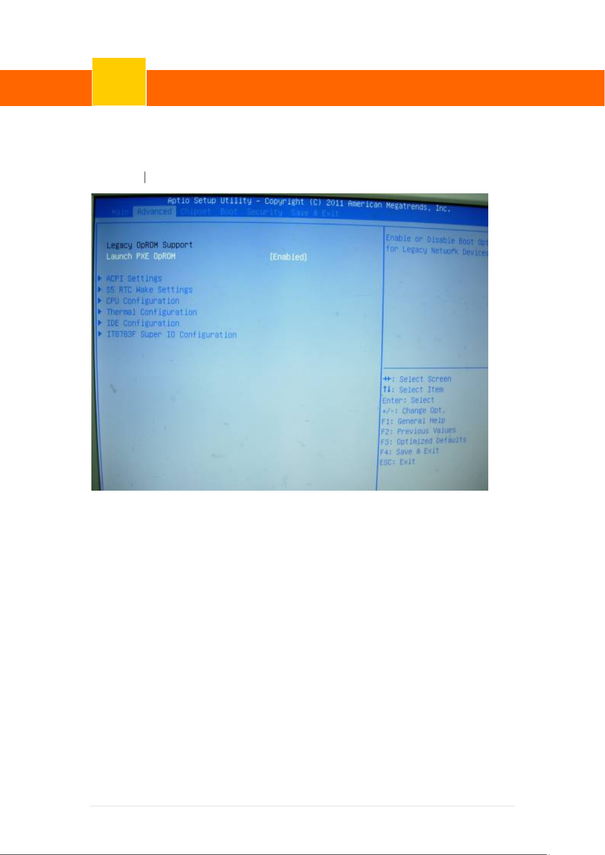
Use the Advanced menu to configure the CPU and peripheral devices through the following
sub-menus:
Launch PXE OPROM: Enable or Disable PXE Funct i on
59 | 72
Page 66
ClientPOS PT8000 User Manual
BIOS/Utility setup
Version: 1.0
7
7-1-1 ACPI Configuration
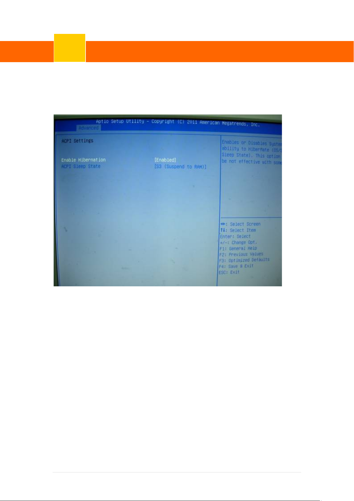
The ACPI Configuration menu configures the A dvanced Configuration and Power Interface
(ACPI) options
ACPI Sleep State
Use the ACP I Sleep State option to sp ecify the sleep state the system enters when it is
not being used.
1. Suspend Disabled
2. S1 (CPU Stop Clock)
DEFAULT The system enters S1 (POS) sleep state. The system appears off. The
CPU is stopped; RAM is refreshed; the system i s running in a low power mode.
3. S3 (Suspend to RAM)
The caches are flushed and the CPU is powered off. Power to the RAM is
maintained. The comput er returns slower to a working state, but more power is
saved.
60 | 72
Page 67
ClientPOS PT8000 User Manual
BIOS/Utility setup
Version: 1.0
7
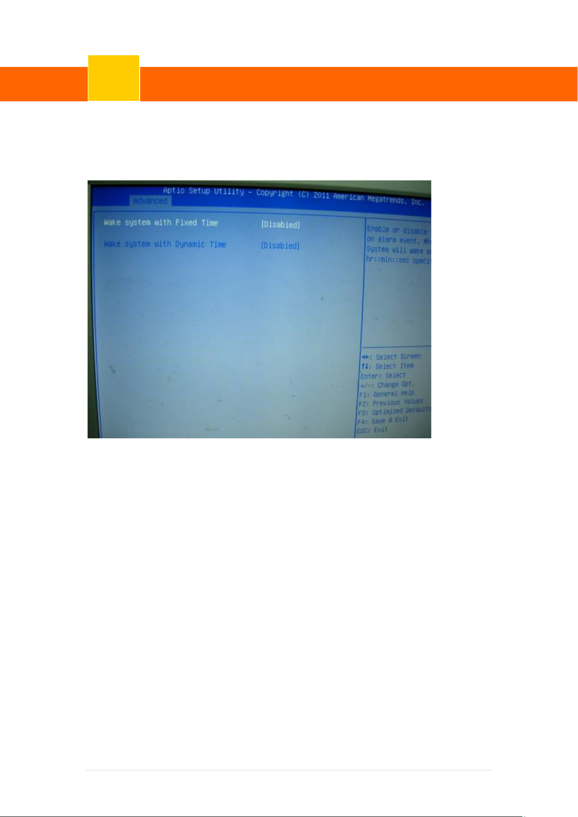
7-1-2 S5 RTC Wake Sett ings
Enable or disable system wake on alarm event. When enabled, system will wake on the
hr::min::sec specified.
61 | 72
Page 68
ClientPOS PT8000 User Manual
BIOS/Utility setup
Version: 1.0
7
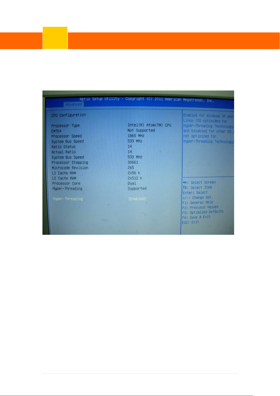
7-1-3 CPU Configur ation
Use the CPU Configuration menu to enter the CPU Information submenu or setup Intel CPU
parameter.
62 | 72
Page 69
ClientPOS PT8000 User Manual
BIOS/Utility setup
Version: 1.0
7
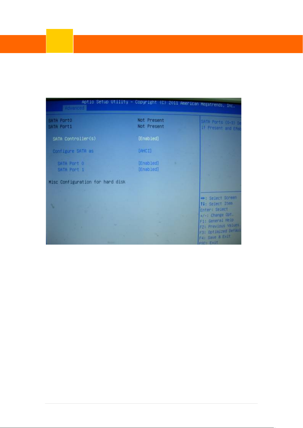
7-1-4 IDE Configuration
Use the SATA Configuration menu to change and/or set the configuration of the SATA devices
installed in the system.
SATA Mode
Use the SATA Mode option to configure SATA devices as normal IDE devices.
Disable Disables SATA devices.
IDE Mode Configures SATA devices as normal IDE dev ice.
RAID Mode Configures SATA devices as RAID device.
63 | 72
Page 70
ClientPOS PT8000 User Manual
BIOS/Utility setup
Version: 1.0
7
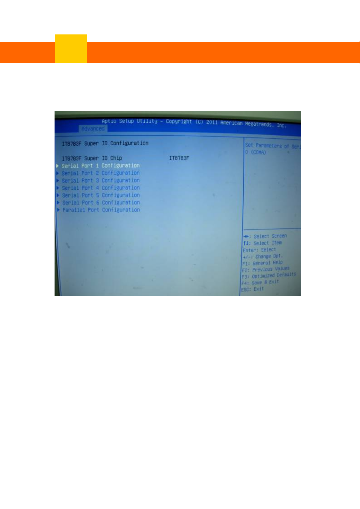
7-1-5 IT8783F Super IO Configuration
Use the Super IO Configuration menu to set or change t he configur ations fo r p ar allel port s a nd
serial ports.
64 | 72
Page 71
ClientPOS PT8000 User Manual
BIOS/Utility setup
Version: 1.0
7
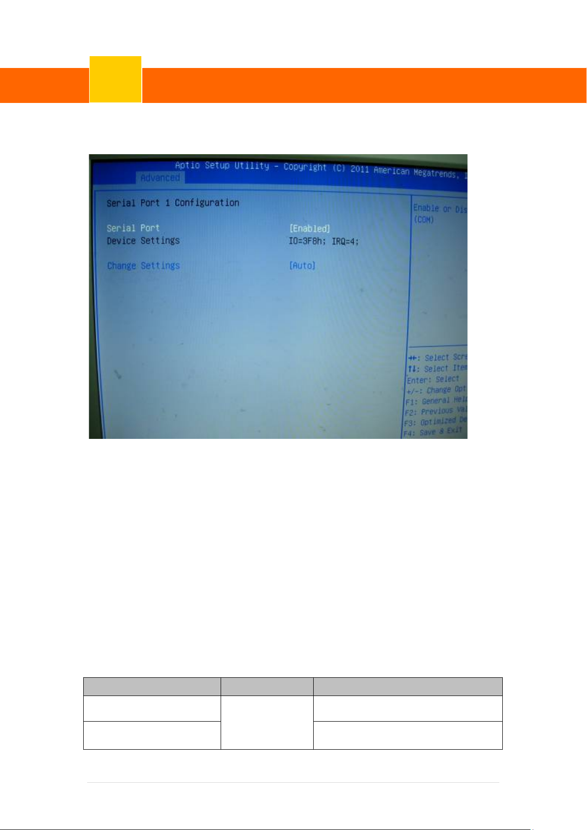
Serial Port n Configuration
Use the Serial Port n Configuration menu to conf i gure the serial port n.
Serial Port [Enabled]
Use the Serial Port option to enable or disable the serial port.
Disabled Disable the serial port
Enabled Enable the serial port
Change Settings [Auto]
Use the Change Settings option to change the se rial port IO port address and interrupt
address.
Auto The serial port IO port address and interru pt address are automatically
detected.
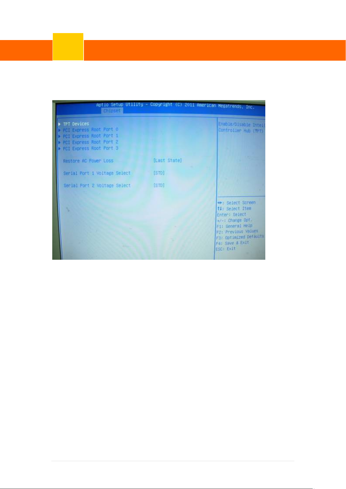
Serial Port 1/2 Voltage Select [STD]
Select "COM1/2 PIN9 Function" and press <Enter> to setup COM 1/2 PIN9 function.
ITEM Option Descriptions
COM1 PIN9 Function STD (Default)
COM1/2 Pin9 select RING function
COM2 PIN9 Function COM1/2 Pin9 select 5V/12V function
5V
12V
65 | 72
Page 72
ClientPOS PT8000 User Manual
BIOS/Utility setup
Version: 1.0
7
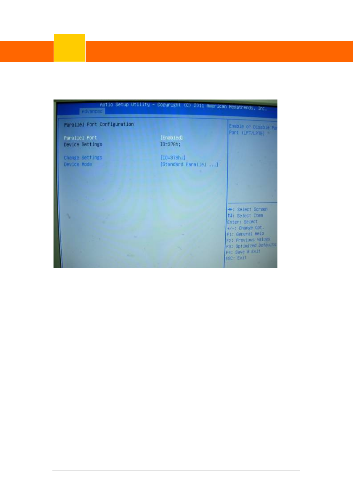
7-1-6 Parallel Port Configuration
Use the Parallel Port Configuration menu to conf i gure the parallel port.
66 | 72
Page 73
ClientPOS PT8000 User Manual
BIOS/Utility setup
Version: 1.0
7
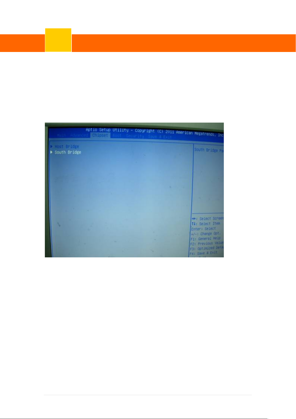
7-2 Chipset
Use the Chipset menu to access the So uthbridge configuration menus
WARNING!
Setting the wrong values for the Chipset BIOS selectio ns in the Chipset BIOS menu may
cause the system to malfunction.
67 | 72
Page 74
ClientPOS PT8000 User Manual
BIOS/Utility setup
Version: 1.0
7
7-2-1 Southbridge Conf iguration
Use the Southbridge Configuration menu to conf i gure the Southbridge chipset.
68 | 72
Page 75
ClientPOS PT8000 User Manual
BIOS/Utility setup
Version: 1.0
7
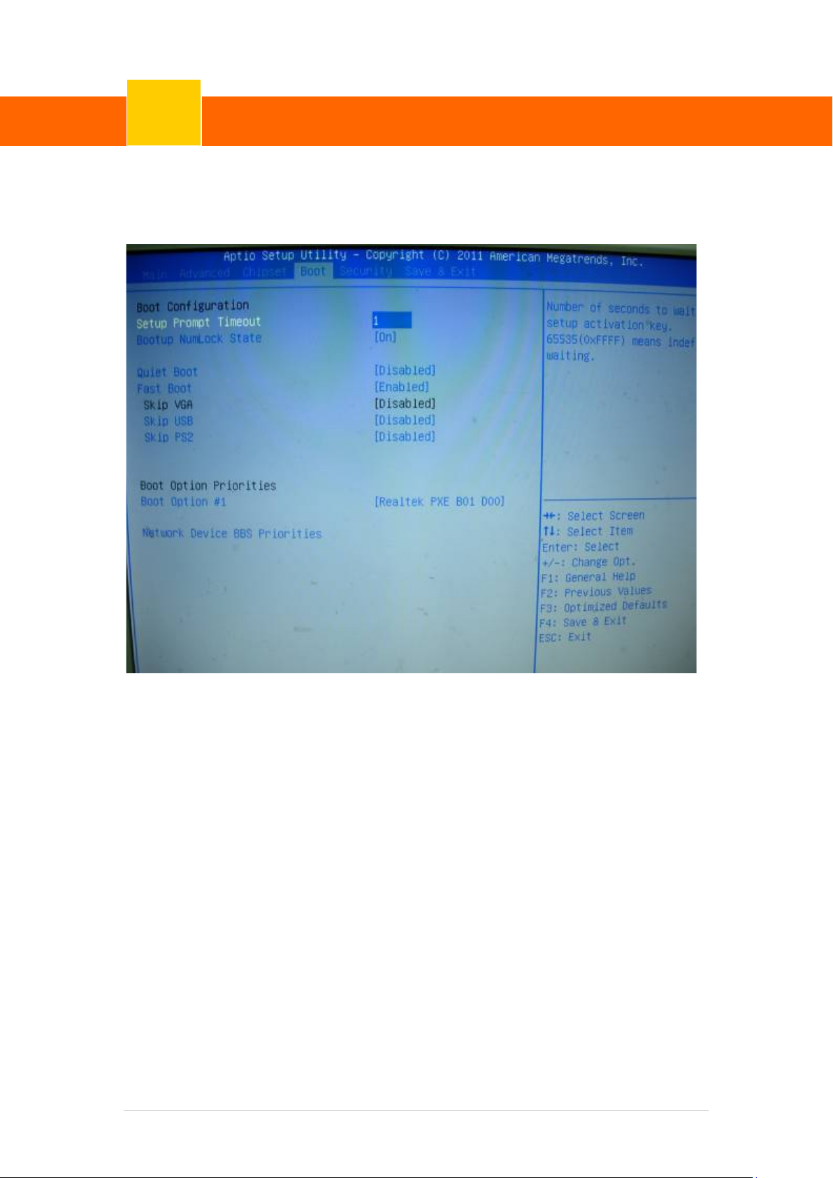
7-3 Boot
Use the Boot menu to configure system boot options.
Bootup NumLock State [On]
Use the Bootup NumLock State BIOS option to specify if the number l ock s etting must be
modified during boot up.
Quiet Boot [Enabled]
Use the Quiet Boot BIOS option to select the scr een d i splay when the system boots.
69 | 72
Page 76
ClientPOS PT8000 User Manual
BIOS/Utility setup
Version: 1.0
7
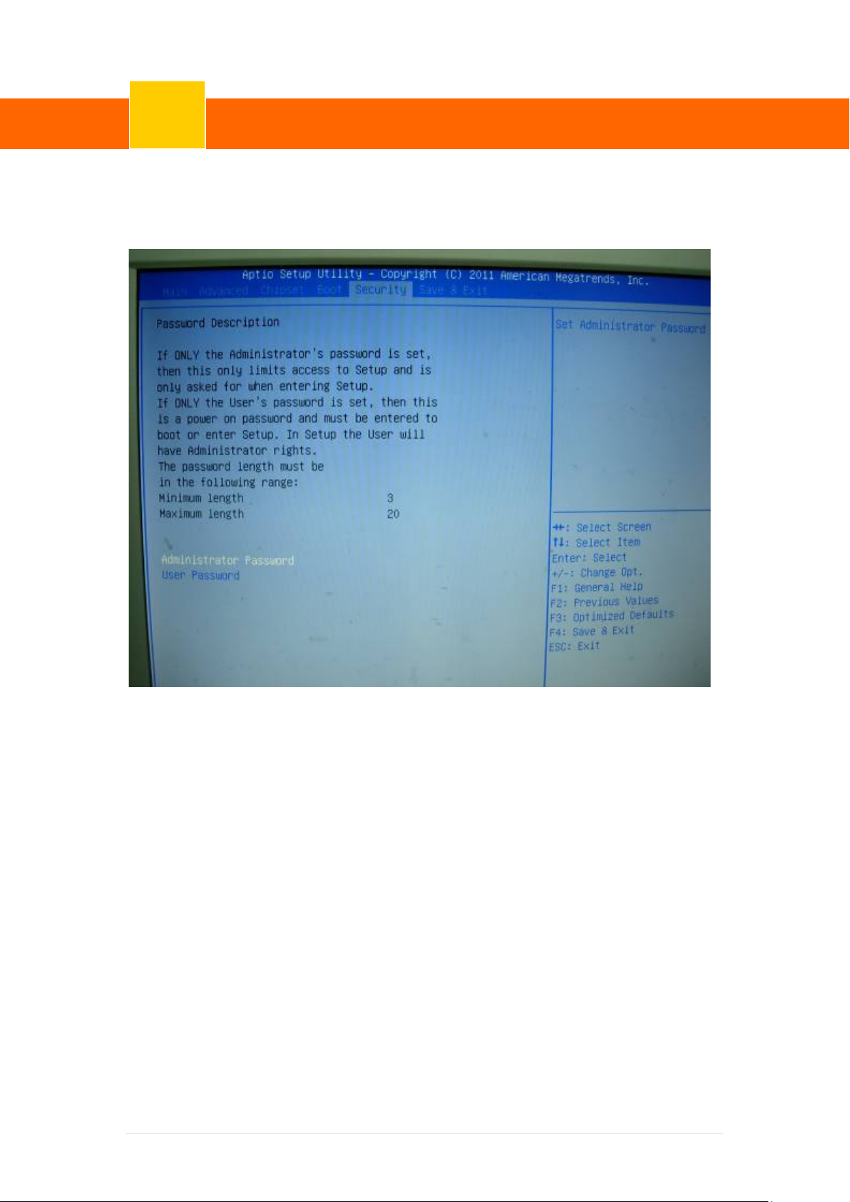
7-4 Security
Use the Security menu to set system and user passwords.
Administrator Password
Use the Adm inistrator Password to set or change an administrator pas sw ord.
User Password
Use the User Password to set or change a user password.
70 | 72
Page 77
ClientPOS PT8000 User Manual
BIOS/Utility setup
Version: 1.0
7
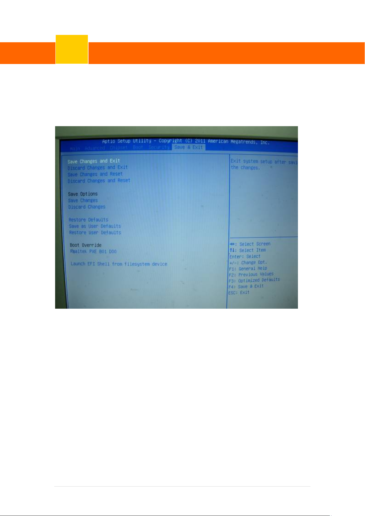
7-5 Save & Exit
Use the Save & Exit menu to load default BIOS values, optimal failsafe values and to save
configuration changes.
71 | 72
Page 78

ClientPOS PT8000 User Manual
LCD Surface Cleaning
8
Version: 1.0
1. How to clean the LCD surface properly?
☆ Do not spray any liquids on the LCD screen directly, and do not use paper t owels,
this can cause the LCD screen to become scratched.
☆ Always apply the solution to your cloth first, not directly t o the parts you are
cleaning. You want to avoid dripping the solution directly into your computer or
laptop.
☆ Stroke the cloth across the display in one direction, moving from the top of the
display to the bottom.
2. What are some of the basic supplies needed to clean an LCD
screen?
☆ A soft cot ton cloth. When cleaning the LCD screen it is important to use a soft
cotton cloth, rather than an old rag. Some m aterials, such as paper towels, could
cause scratches and damage the LCD screen.
☆ Solution of water and isopropyl alcohol. Thi s solution can be used along with the
soft cotton cloth.
☆ Computer wipes. Only use these if they specifically state on the package they are
designed for LCD laptop screens. Computer wipes can come in handy for fast
clean-ups or when you want to avoid mixing up a cleaning solution yourself.
3. What types of cleaners are acceptable?
☆ Water
☆ Vinegar (mixed with water)
☆ Isopropyl Alcohol
NOTICE: The following cleaners are unacceptable:
☆ Acetone
☆ Ethyl alcohol
☆ Ethyl acid
☆ Ammonia
☆ Methyl chloride
72| 72
 Loading...