

manual
V1.0 May 2018WWW.CLF-LIGHTING.COM
SPECTRUM P2 VARI-WHITE
S
PECTRUM P
2
V-W

table of CONTENTS
WWW.CLF-LIGHTING.COM
Dimensions
1
Safety Informat io n
2
Fixture overvie w
4
Introduction
5
AC power
5
Power voltage
5
Power cables
6
Relaying power to o th er devices
6
Data link
6
Tips for reliable da ta t ransmission
6
Physical instal la tion
7
Fastening the fix tu re to a flat surface
7
Setup
8
Control panel and m en u navigation
8
DMX address setti ng
8
Control Mode
9
Static Color opti on s
10
Auto Show
11
Master / Slave
11
Personality
11
Dimmer speed
11
Dimmer curve
11
Key-Lock
11
Refresh rate
11
LCD brightness
11
DMX HOLD
11
Dimmer mode
12
Information
12
Software type
12
Usage time
12
Temperature
12
UID
12
Factory reset
12
DMX protocols
13
Onboard control m en us
15
Exploded view
16
Specification s
17
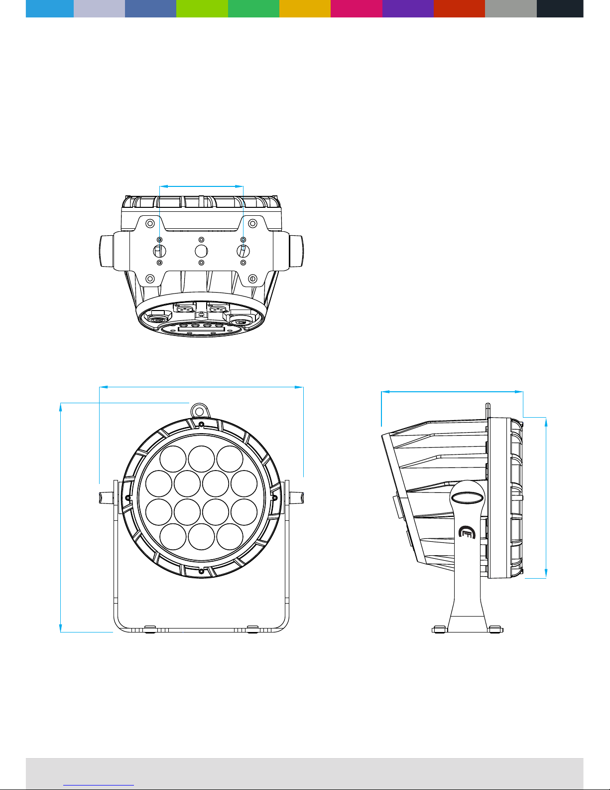
Dimensions
All dimensions are in millimeters
WWW.CLF-LIGHTING.COM
1.0
SPECTRUM P2
V-W
106
260
290
Φ203
180
WWW.CLF-LIGHTING.COM
2.0
The fo llowing symbols are used to identi fy important safety informatio n on the product and in this manual:
WARNING!
Read the safety precautions in this section before
installing, powering, operating or servicing this
product
DANGE R!
Safet y ha zard.
Risk of s ev ere
injur y or d eath.
DANGE R!
Hazar do us
volta ge . Risk of
letha l or s evere
elect ri c shock .
WAR NING!
Fire ha za rd.
WAR NING!
LED lig ht
emiss io n. Risk o f
eye inj ur y.
WAR NING!
Burn ha za rd. Hot
surfa ce . Do not
touch .
WAR NING!
Wear pr otect ive
eyewe ar .
WAR NING!
Refer t o us er
manua l.
Warning! Risk Group 3 (high risk) LED product according to EN 62471. Do not look into the beam at a distance
of less than 3 meters from the front surface of the product. Do not view the light output with optical instruments
or any device that may concentrate the beam.
This product is for professional use only. It is not for household use.
This product presents risks of severe injury or death due to fire and burn hazards, electric shock and falls.
Read this manual before installing, powering or servicing the fixture, follow the safety precautions listed below and
observe all warnings in this manual and printed on the fixture. If you have questions about how to operate the fixture
safely, please contact your supplier.
PROTECTION FROM ELECTRIC SHOCK
l Disconnect the fixture from AC power before removing or installing any cover or part and when not in use.
l Always ground (earth) the fixture electrically.
l Use only a source of AC power that complies with local building and electrical codes and has both overload and
ground-fault (earth-fault) protection.
l Before using the fixture, check that all power distribution equipment and cables are in perfect condition and rated for
the current requirements of all connected devices.
l Power input and through out cables must be rated 20A minimum, have three conductors 1.5 mm² (16 AWG) minimum
conductor size and an outer cable diameter of 5 - 15 mm . Cables must be hard usage type (SJT or equivalent) and
heat-resistant to 90° C minimum.
l Use only cable connectors to connect to power input sockets. Use only
® ®
PowerCON TRUE 1 PowerCON TRUE 1
cable connectors to connect to power through put sockets.
l Isolate the fixture from power immediately if the power plug or any seal, cover, cable, or other component is
damaged, defective, deformed, wet or showing signs of overheating. Do not reapply power until repairs have been
completed.
WWW.CLF-LIGHTING.COM
3.0
Do not expose the fixture to rain or moisture
l Refer any service operation not described in this manual to a qualified technician.
l Socket outlets used to supply the fixture with power or external power switches must be located near the fixtures and
easily accessible so that the fixtures can easily be disconnected from power.
PROTECTION FROM BURNS AND FIRE
l Do not operate the fixture if the ambient temperature (Ta) exceeds 40°C.
l The exterior of the fixture becomes hot during use. Avoid contact by persons and materials.
Allow the fixture to cool for at least 10 minutes before handling.
l Keep all combustible materials (e.g. fabric, wood, paper) at least 100 mm away from the fixture.
l Keep flammable materials well away from the fixture.
l Ensure that there is free and unobstructed airflow around the fixture.
l Do not illuminate surfaces within 200 mm of the fixture.
l Do not attempt to bypass thermostatic switches or fuses.
l If you relay power from one fixture to another using power throughput sockets, do not connect more than ten the
fixture in total to each other in an interconnected chain.
l Connect only other the fixture to fixture power throughput sockets. Do not connect any other type of device to these
sockets.
l Do not connect any other type of device to these sockets.
l Do not stick filters, masks or other materials onto any optical component, besides the optional CLF Yara filters.
l Do not modify the fixture in any way not described in this manual.
l Do not use fixture on a dimmer.
PROTECTION FROM INJURY
l Do not look continuously at LEDs from a distance of less than 3 meters from the front surface of the fixture without
protective eyewear such as shade 4-5 welding goggles. At less than this distance, the LED emission can cause eye
injury or irritation. At distances of 3 meters and above, light output is harmless to the naked eye provided that the
eye’s natural aversion response is not overcome.
l Do not look at LEDs with magnifiers, telescopes, binoculars or similar optical instruments that may concentrate the
light output.
l Ensure that persons are not looking at the LEDs from within 3 meters when the product lights up suddenly. This can
happen when power is applied, when the product receives a DMX signal, or when SERVICE menu items are
selected.
l Fasten the fixture securely to a fixed surface or structure when in use.
l Ensure that any supporting structure and/or hardware used can hold at least 10 times the weight of all the devices
they support.
l Allow enough clearance around the fixture to ensure that it cannot collide with an object or another fixture when it
moves.
l Check that all external covers and rigging hardware are fastened securely.
l Block access below the work area and work from a stable platform whenever installing, servicing or moving the
fixture.
l Do not operate the fixture with missing or damaged covers, shields or any optical component.

WWW.CLF-LIGHTING.COM
4.0
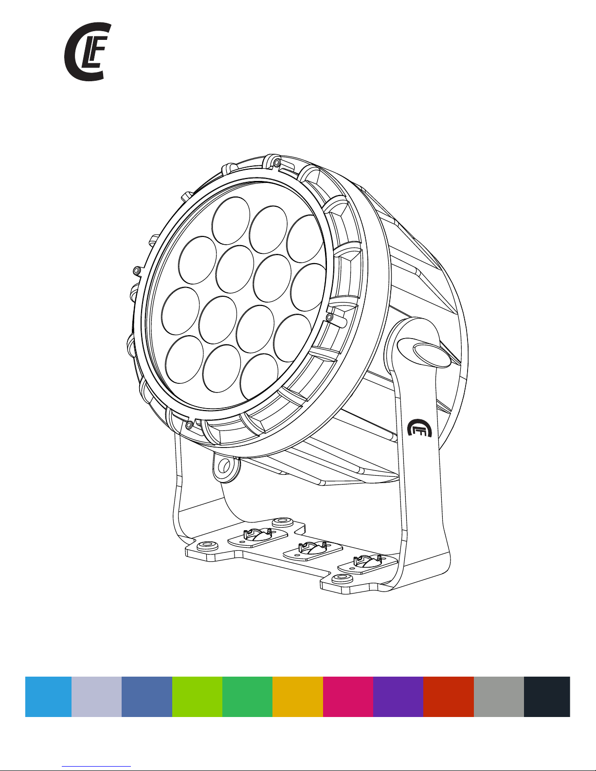
fixture overview
Control buttons
Safety cable
attachment point
LCD Display
5P DMX input
5P DMX output
AC mains power
throughput
AC mains power
input
G Clamp with
Quicklock # 875760
(Optional)
Omega bracket with
Quicklock # 520114
(Optional)
3P DMX input (optional)
# CLF-13-453
3P DMX output (optional)
# CLF-13-454
P2
VARI- WHITE
SPECTRUM

WWW.CLF-LIGHTING.COM
5.0
Introduction
Warning! Read “Safety Information” on page 2 before installing, powering, operating or servicing the fixture.
Before applying power to the fixture:
l Check that the local AC mains power source is within the fixture’s power voltage and frequency ranges.
l See “Power cables and power plug” on page 6. Install a power input connector on a suitable
®
PowerCON TRUE 1
power cable.
Using for the first time
Outdoor C+W LED Fixture
Affordable lighting essential
¢ Unique bracket design
¢ Touring proof
¢ Smooth Cool white + Warm white mixing
¢ Ip65 rating
¢ Silent operation
¢ Smooth projection
®
¢ Powercon true 1
in & out
¢ RDM ready
AC power
War ni ng! Read “Safety Information” starting on page 2 before connecting the fixtures to AC mains power.
War ning! For protection from electric shock, the fixture must be grounded (earthed). The power
distributioncircuit must be equipped with a fuse or circuit breaker and ground-fault (earth-fault) protection.
War ning! Socket outlets or external power switches used to supply the fixture with power must be
located near the fixture and easily accessible so that the fixtures can easily be disconnected from power.
Important! Do not i ns ert or remove live connectors to app ly o r cut power, as this
®
PowerCON TRUE 1
may cause arcing at t he t erminals that will da ma ge the connectors .
Important! Do not u se a n external dimming sy st em to supply power to t he f ixture, as this may cau se
damage to the fixtu re t hat is not covered by the p ro duct warranty.
The fixture can be ha rd -wired to a electrica l in stallation if you wan t to i nstall it permanent ly, or a power plug
that is suitable fo r th e local power outlets c an b e installed on the powe r ca ble.
power voltage
War ni ng! Check that the volt ag e range specified on th e fi xtures serial num be r la bel matches the loc al
AC mains power volt ag e be fore applying pow er t o the fixture.
The fixtures acce pt s AC mains power at 100-24 0 V no minal, 50/60 Hz. Do not a pp ly AC mains power to the
fixture at any othe r vo ltage than specifie d.

WWW.CLF-LIGHTING.COM
6.0
power cables
Power input and thr ou ghput cables must be ra te d 20A minimum, have thre e co nductors 1.5 mm² (16 AWG)
minimum conduct or s ize and an outer cable di am eter of 5 - 15 mm. Cables mus t be h ard usage type (SJT or
equivalent) and h ea t- resistant to 90°C mi ni mum. In the EU the cable mu st b e HAR approved or equiv al ent.
If you install a powe r pl ug on the power cable, in st all a grounding-typ e (e arthed) plug that is ra te d 20A
minimum. Follow t he p lug manufacturer’s instru ct ions. Table 1 shows s ta ndard wire color- co di ng schemes
and some possible p in i de ntification sch em es; if pins are not clear ly i dentified.
Relaying power to other devices
War ni ng! Do not connect more t ha n ten fixtures in tot al t o AC ma ins power in one inte rc on nected chain.
Power can be relaye d to a no ther device via the throughput sock et .
®
PowerCON TR UE 1
If you daisy chain th e fi xtures in a chain so that t he y all draw AC mains power vi a th e first fixture, ce rt ai n
points must be resp ec ted:
2
• A he avy duty, thre e- co nductor, 16 AWG or 1.5 mm cable with SJT or e quivalent cable jac ke t must be used to
connect the first f ix ture to AC mains power.
• connectors must be used to draw AC mains power from the fixtures power throughput
®
PowerCON TR UE 1
sockets and yellow connectors must be used to supply power at the fixture’s power input
®
PowerCON TRUE 1
sockets.
• No matter what the AC ma in s power voltage is, do no t co nnect more than ten the f ix ture in total ( inclu di ng
the first fixture ) to AC m ains power in one inter co nnected daisy chain u si ng power input and thro ug h out
connectors.
A DMX 512 data link is req ui re d in order to control a f ix ture via DMX. The f ixture has 5-pin XLR co nn ectors for
DMX data input and ou tp ut. The pin-o ut o n al l connectors is pin 1 = s hi eld, pin 2 = cold (-), and pi n 3 = ho t (+)
Pins 4 and 5 in the 5-pin X LR c onnectors are not use d.
tips for reliable data transmission
To connect the fixtur e to d ata:
1. Conn ect the DMX data output from the controller to the 5-pin XLR connector of t he n earest fixture.
2. Connect the DMX ou tp ut of the fixture close st t o the controller to the D MX i nput of the next fixt ur e and
continue connec ti ng fixtures output to i np ut.
Wire Color (EU models)
Wire Color (US models)
Conductor
Symbol
Brown
Black
LiveLBlue
White
Neutral
N
Yellow/Green
Green
Ground (earth)
or
DATA LINK
Table 1 : Wire color-coding and power connections

WWW.CLF-LIGHTING.COM
7.0
Physical installation
War ni ng! The fixtu re m ust be either fastene d to a f lat surface such as a sta ge o r wall, or clamped to a t ru ss or
similar structu re i n any orientation usi ng a r igging clamp.
War ni ng! If the fixture can ca us e injury or damage it if fa ll s, attach an approv ed s afety cable to one of the
safety cable atta ch ment points on the base ( se e “Fixture overview ” on p age 4).
Check that all surf ac es to be illuminated ar e mi nimum 200 mm. from the fi xt ure, that combust ib le m aterials
(wood, fabric, pa pe r, etc.) are minimum 100 m m. f rom the fixture, that t he re is free airflow ar ou nd the fixture
and that there are no f la mmable materials ne ar by.
Fastening the fixture to a flat surface
The fixture can be fa st ened to a fixed flat surf ac e that is oriented at any a ng le. Check that the su rf ace can
support at least 10 t im es the weight of all fixt ur es and equipment to be in st alled on it.
War ni ng! The suppo rt ing surface must be har d an d flat or air vents in the ba se m ay be blocked, which wi ll
cause overheati ng . Fasten the fixture se cu rely. Do not sta nd i t on a surface or leave it wh er e it can be moved
or can fall over. Attac h a se curely anchored saf et y cable to the safety cab le a ttachment point (se e “F ixture
overview” on page 4 ) if t he fixture is to be insta ll ed in any location wher e it m ay fall and cause injur y or
damage if the prima ry a ttachment fails.
1. Block access und er t he work area. Wor ki ng from a stable plat fo rm, hang the fixture on t he t russ. Tighten
the rigging clamp .
2. Secure the fixtu re a gainst clamp failur e wi th a secondary attach me nt such as an approve d sa fe ty cable
that is rated for the w ei ght of the fixture usin g on e of the attachment poi nt s at the edges of the bas e (s ee
“Fixture overvi ew ” on page 4). Do not use any ot he r part of the fixture as a sa fe ty cable attachme nt p oint.

WWW.CLF-LIGHTING.COM
8.0
SETUP
War ni ng! Read “Safety Info rm ation” on page 2 before i ns talling, poweri ng , op erating the fixtu re .
Control panel and menu navigation
The onboard contr ol p anel and backlit grap hi c display are used to set t he f ixture’s DM X ad dress, configure
individual fixt ur e settings (persona li ty), read out data and ex ec ute service utiliti es . See “Onboard cont ro l
menus” on page 11 fo r a complete list of me nu s an d commands.
Using the control b ut tons
• To enter the menu s el ect [MODE].
• Press [UP] and [DOW N] t o scroll within a menu or a dj ust values.
• To enter a menu, se le ct a function or appl y a se le ction, press [ENT ER ].
• To escape a funct io n or move back one level in t he m enu structure, pr es s [MODE].
• Holding down the "U P" a nd " DOWN" button for mo re t han 3 seconds, the MENU d is play will rotate 180° .
• Menu = Manual
• Enter = Test mode
DMX address setting
The DMX address, also known as the start channel, is the first channel used to receive instructions from the controller.
For independent c on trol, each fixture mu st b e assigned its to a separ at e channel .
The DMX address can b e co nfigured by using the D MX AD DRESS menu in the contr ol p anel. For setting the
DMX address press [ EN TER] before you can cha ng e the address.
• The main scre en w ill show a 'dot' and the ba ck light will be switc he d off when a DMX sign al i s detected.
• The fixture i s fu lly RDM ready. So wh en you are using a RDM read y co nsole you can address t he u nit and
read out its comple te s tatus. For RDM functi on s please refer to the ANSI /E STA E1.20-200 6 st an dard

WWW.CLF-LIGHTING.COM
9.0
Control mode
DMX control mode is s el ected in the CONTROL MO DE m enu. The fixture has 5 DM X co ntrol modes:
2ch
3ch
4ch
5ch
6ch
Dimmer
Cool white
Warm white
CCT
Strobe
Fade

WWW.CLF-LIGHTING.COM
10.0
Static Color options
There are three options for static color:
1. FIXED Color
Several options from combinated warm white and cool white values. Use Up and Down to scroll through the options.
2. CCT
Easy color choice between 2800K (warm white) to 6000K (cood white)
3. Manual Color
Mix your own color with each warm white and cool white value seperately.
Cool White
Warm white
CW+WW
Dimmer
<000-255>
Dimmer
CW
<000-255>
Dimmer Cool white
WW
<000-255>
Dimmer Warm white
Strobe
<00-20>
Strobe <00-20Hz>
2800 K
4500 K
3200 K
4800 K
3500 K
5000 K
3800 K
5500 K
4000 K
6000 K

WWW.CLF-LIGHTING.COM
11.0
Auto show
The auto function gives which are working without any DMX console. Hit [ENTER] to adjust the 3 auto programs
speed of the program from 1-3.Auto
Master/Slave
You can choose between master or slave functioning. The chosen mode is visible in the homescreen. The fixture will
automatically go to slave function when no DMX signal is offered.
1) Auto 1
Auto program 1
2) Auto 2
Auto program 2
3) Auto 3
Auto program 3
Here you can set all functions for the fixture.
personality
Dimmer Speed
Normal / Smooth 1 / Smooth 2 / Smooth 3 / Smooth 4
Dimmer curve
lin
e
a
r / S
qu
are law / INV S
qua
re l
aw / S- C
urv
e / Spe
c
ia
l
KEY-Lock
Locks
all
the
button
functions
.
Standard
unlocking
password
is
(MODE+UP+MODE+DOWN+MODE+UP+MODE+DOWN+ENTER)
Refresh rate
Controls the
Flicker
frequency
of
the
fixture
600
1200
2400
4800
L
CD b
r
ig
h
tne
s
s
Set the
LCD display
brightness(1-10)
DMX HOLD
DMX HOLD =
The
fixture
will
remember
on
last
values
when
you
disconnect DMX
NO DMX HOLD =
The
fixture has
no
output when
you
disconnect DMX

WWW.CLF-LIGHTING.COM
12.0
Software type
Shows
software
version (
Vx.
x)
Usage time
Us
e of t
ime a
n
d u
se t
ime r
ese
t
(
pas
s
w
or
d
)
T
emperature
L
E
D
b
oa
r
d
c
ur
r
e
nt
tem
p
e
ra
ture
U
I
D
S
h
o
w
s t
h
e u
niq
u
e I
D f
o
r th
e R
DM p
rotoc
oll. <
0x
0
2E
200
0
2
x
xx
x
>
Information
Factory reset
Resets the fixture to its factory default settings.
Please reboot power before reset takes effect.
DIMMER MODE
provides five dimming options (see picture below):
Output
Output
Output
Output
DMX %
LINEAR
DMX %
SQUARE LAW
DMX %
INVERSE SQUARE LAW
DMX %
S-CURVE
Output
DMX % Up DMX % Down
SPECIAL
l LINEAR – the increase in light intensity appears to be linear as DMX value is increased.
l SQUARE LAW – light intensity control is finer at low levels and coarser at high levels.
l INV Square law – light intensity control is coarser at low levels and finer at high levels.
l S-CURVE – light intensity control is finer at low levels and high levels and coarser at medium levels.
l Special – the light intensity was linear increase with DMX value , and light intensity control is finer at low level
with DMX values decrease , the dimmer speed will also has effect on it
Whichever DIMMER CURVE option you select, you can choose between NORMAL or SMOOTH 1 / 2 / 3 / 4 dimming
settings:
l NORMAL is the default setting. It gives a virtually instantaneous reaction when you dim from one intensity to
another, but dimming slowly from one intensity to another may appear slightly uneven.
l The MOOTH 1 / 2 / 3 / 4 setting gives smoother dimming during slow changes in intensity, but it limits the speed
of dimming changes slightly. This makes it ideal for slow, smooth dimming, but a short time-lag may be
noticeable if you try to dim quickly from one intensity to another.

WWW.CLF-LIGHTING.COM
13.0
dmx protocols
2CH
Function
Value
Setting
Remark
1
Cool white
000 - 255
0 - 100%
2
Warm white
000 - 255
0 - 100%
3CH
Function
Value
Setting
Remark
1
Dimmer
000 - 255
0 - 100%
2
Cool white
000 - 255
0 - 100%
3
Warm white
000 - 255
0 - 100%
4CH
Function
Value
Setting
Remark
1
Dimmer
000 - 255
0 - 100%
2
Cool white
000 - 255
0 - 100%
3
Warm white
000 - 255
0 - 100%
4
CCT
000 - 009
010 - 255
No function
6000K - 2800K
5 CH
Function
Value
Setting
Remark
1
Dimmer
000 - 255
0 - 100%
2
Cool white
000 - 255
0 - 100%
3
Warm white
000 - 255
0 - 100%
4
CCT
000 - 009
010 - 255
No function
6000K - 2800K
5
Strobe
000 - 024
025 - 064
065 - 069
070 - 084
085 - 089
090 - 104
105 - 109
110 - 124
125 - 129
130 - 144
145 - 149
150 - 164
165 - 169
170 - 184
185 - 189
190 - 204
205 - 209
210 - 224
225 - 229
230 - 244
245 - 255
Shutter open
Strobe 1 (fast → slow )
Shutter open
Strobe 2: opening p ul se (fast → slow)
Shutter open
Strobe 3: closing p ul se (fast → slow)
Shutter open
Strobe 4: random st ro be (fast → slow)
Shutter open
Strobe 5: random op en ing pulse (fast → slow)
Shutter open
Strobe 6:random c lo sing pulse (fast → slow )
Shutter open
Strobe 7: burst pul se ( fast → slow)
Shutter open
Strobe 8: random bu rs t pulse (fast → slow)
Shutter open
Strobe 9:sine wav e (f ast → slow)
Shutter open
Strobe 10: burst (f as t → slow)
Shutter open

WWW.CLF-LIGHTING.COM
14.0
dmx protocols
6 CH
Function
Value
Setting
Remark
1
Dimmer
000 - 255
0 - 100%
2
Cool white
000 - 255
0 - 100%
3
Warm white
000 - 255
0 - 100%
4
CCT
000 - 009
010 - 255
No function
6000K - 2800K
5
Strobe
000 - 024
025 - 064
065 - 069
070 - 084
085 - 089
090 - 104
105 - 109
110 - 124
125 - 129
130 - 144
145 - 149
150 - 164
165 - 169
170 - 184
185 - 189
190 - 204
205 - 209
210 - 224
225 - 229
230 - 244
245 - 255
Shutter open
Strobe 1 (fast → slow )
Shutter open
Strobe 2: opening p ul se (fast → slow)
Shutter open
Strobe 3: closing p ul se (fast → slow)
Shutter open
Strobe 4: random st ro be (fast → slow)
Shutter open
Strobe 5: random op en ing pulse (fast → slow)
Shutter open
Strobe 6:random c lo sing pulse (fast → slow )
Shutter open
Strobe 7: burst pul se ( fast → slow)
Shutter open
Strobe 8: random bu rs t pulse (fast → slow)
Shutter open
Strobe 9:sine wav e (f ast → slow)
Shutter open
Strobe 10: burst (f as t → slow)
Shutter open
6
Fade
000
1 - 255
No function
Dimmer Speed

WWW.CLF-LIGHTING.COM
15.0
Onboard control menus
NO.
Main Menu
Menu level 2
Menu level 3
Remark
1
DMX ADDRESS
<001>
Default 001
2
CONTROL MODE
2CH
1. Cool white 2.Warm white,
Default : 5CH
3CH
1. Dimmer, 2. , 3.Cool white Warm white
4CH
1. Dimmer, 2. , 3. , 4.CCT.Cool white Warm white
5CH
1. Dimmer, 2. , 3. , 4.CCT, Cool white Warm white
5,Strobe
6CH
1. Dimmer, 2. , 3. , 4.CCT, Cool white Warm white
5.Strobe. 6,Fade
3
PERSONALITY
Dimmer Speed
Normal
Default : Normal
Smooth 1
Smooth 2
Smooth 3
Smooth 4
Dimmer curve
linear
Square law
INV Square law
S-Curve
Special
Default : linear
Key-Lock
ON/OFF
Default : OFF
Refresh rate
600/1200/2400 /4 80 0
Default : 4800
LCD brightness
Level(1 - 10)
DMX HOLD
DMX HOLD
NO DMX HOLD
Default : DMX HOLD
4
STATI C CO LOR
Fixed color
CW WW CW+WW
Default : CW+WW
CCT
2800K, 3200K, 350 0K , 3800K, 4000K, 4500K ,
4800K, 5000K, 550 0K , 6000K
Default : 4000K
Manual color
Dimmer 0-255
Default : 255
CW 0-255
Default : 255
WW 0-255
Default : 255
Strobe 0-20
Default : 0
5
AUTO
AUTO 1
Speed 0 2 0-
Default : Speed 0
AUTO 2
Speed 0 2 0-
Default : Speed 0
AUTO 3
Speed 0 2 0-
Default : Speed 0
6
INFO
Software type
VX.XX
Usage time
TOTAL Xxxx H
Temperature
XXX℃
UID
0x02E2000xxxx x
7
FACTORY RES ET
LOAD
Please reboot pow er b efore reset takes effect!

WWW.CLF-LIGHTING.COM
16.0
exploded view
NO.
Description
Part Number
1
Front Cover ring CLF-14-003
2
Rubber glass ring CLF-14-010
3
Tempered front glass CLF-14-013
4
Lens kit
CLF-19-002
5
LED board CLF-19-006
6
LED board radiator CLF-14-002
7
Fan
CLF-14-016
8
Fan cover
CLF-14-017
9
Power supply
CLF-14-015
10
Power supply support bracket CLF-14-007
11
Case body CLF-14-001
12
Display board
CLF-19-005
13
Display
sticker
CLF-19-004
14
Acrylic display support CLF-14-012
15
PowerCON TRUE1 input socket
CLF-14-027
16
PowerCON TRUE1 output socket
CLF-14-028
17
DMX 5 pin male chassis part waterproof
CLF-14-032
18
DMX 5 pin female chassis part waterproof CLF-14-031
19
Valve CLF-14-023
20
Knob for bracket CLF-14-014
21
Bracket CLF-19-003

WWW.CLF-LIGHTING.COM
17.0
Specifications
Physical
Length
260mm
Width
180mm
Height
295mm
Weight
3.8 kg without accessories
Dynamic Efects
beam angle
15°
Optics
Light source
14 pcs high-power LED (cool white + Warm white)
Control and Programming
Control
DMX512-A
DMX channels
2 / 3 / 4 / 5 / 6
Setting and addressing
Control panel with backlit LCD graphic display
Protocol
RDM, USITT DMX512-A
Control and Programming
Color
Black
Housing
High strength die-casting aluminum
Protection rating
IP 65 ( If rubbers covers are place correctly when connectors are not used )
Installation
Orientation
Any
Minimum distance to combustible materials
100 mm. from fixture
Minimum distance to illuminated surfaces
200 mm. from fixture
Connections
AC power input
®
PowerCON TRUE 1 input socket
AC power throughput
®
PowerCON TRUE 1 output socket
DMX data in/out
5 pin locking XLR (3 pin optional with # CLF-13-453 & CLF-13-454)
Electrical
AC power
100-240 V nominal, 50/60 Hz
Maximum total power consumption
110 W
Power supply unit
Auto-ranging electronic switch mode
Power consumption, all efects static, zero light output
<15 W
Power consumption
120 V, 60 Hz
105 W, PF * 0.985
240 V, 50 Hz
101 W, PF * 0.829
* PF = power factor. Measurements made at nominal voltage with all LEDs at full intensity. Allow for a deviation of +/- 10%.
Cooling
Passive
Maximum ambient temperature (Ta max.)
40° C
Minimum ambient temperature (Ta min.)
5° C
Total heat dissipation (calculated, +/- 10%)
820 BTU/hr.

WWW.CLF-LIGHTING.COM
CLFLIGHTING
SPECTRUM P2 VARI-WHITE
 Loading...