

CLF Lighting Orion User Manual
manual
WWW.CLF-LIGHTING.COM V1.0 OCTOBER 2018
orion

table of CONTENTS
Dimensions 1
Safety Instruction 2
Fixture overview 4
Introduction 5
AC Power 5
Power voltage 5
Power cables 6
Relaying power to other devices 6
Data link 6
Tips for reliable data transmission 6
Physical installation 7
Fastening the xture to a at surface 7
Outdoor IP-rated xtures 8
Condensation/moisture inside housing 8
Fixtures temperature specication 8
Setup 9
Control panel and menu navigation 9
DMX address setting 9
Onboard control menus 10
DMX protocol 15
Gobo overview 22
Photometrics 23
Circuit connection diagram 24
Specifications 25
WWW.CLF-LIGHTING.COM
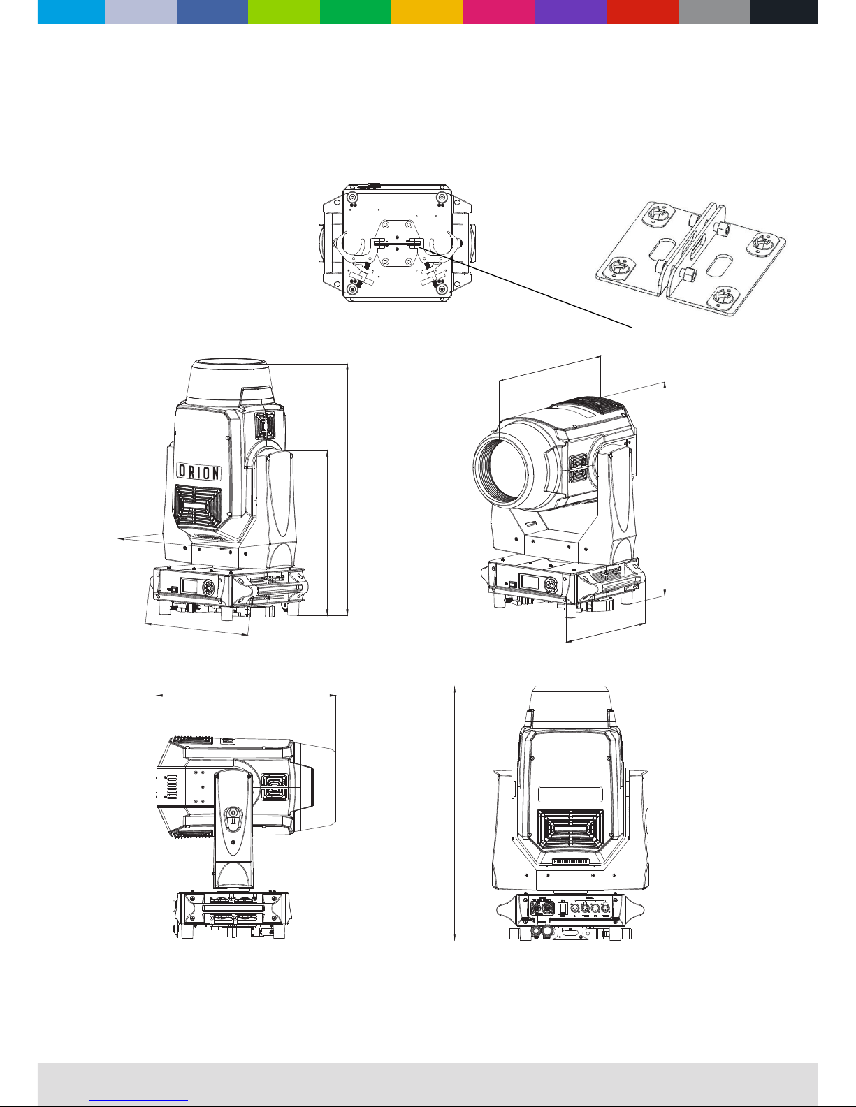
Dimensions
All dimensions are in millimeters
WWW.CLF-LIGHTING.COM
1
orion
654
438
380
654
300
521
460
460,29
401
OPTIONAL HANGING BRACKET
ART. NO. 160022
Safety Instruction
WWW.CLF-LIGHTING.COM
2
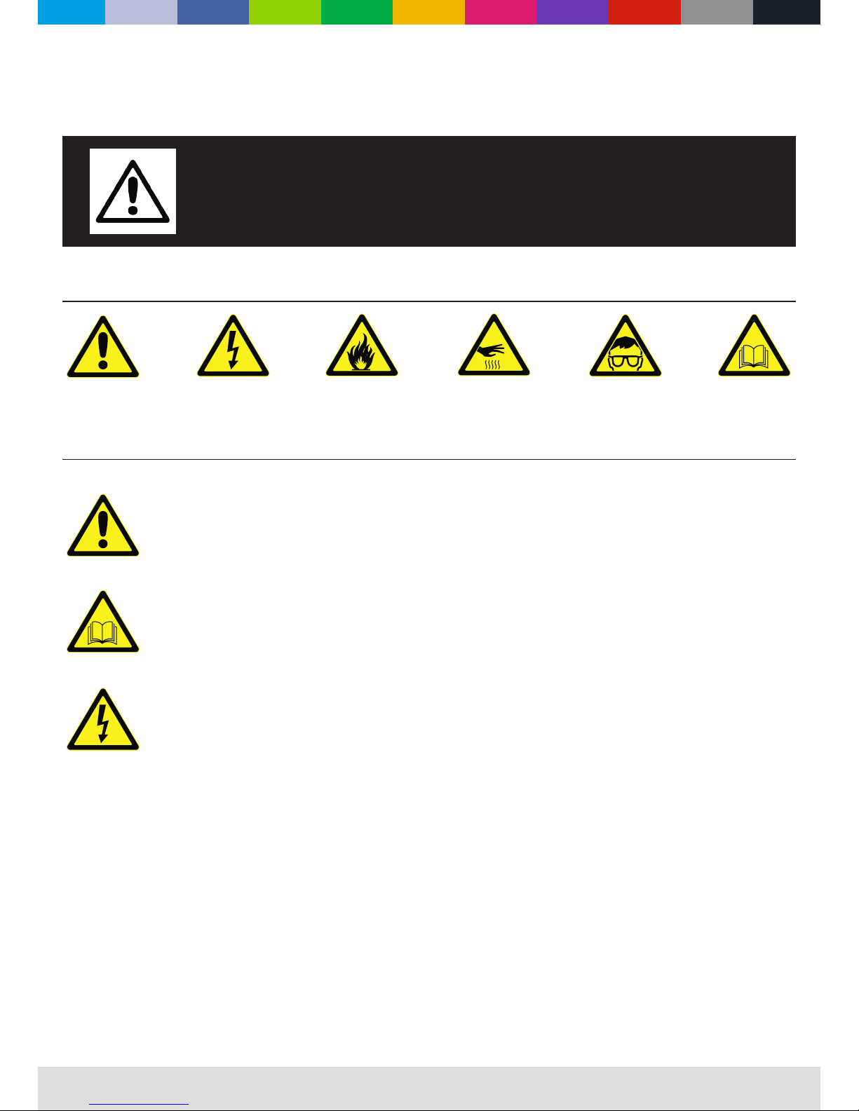
WARNING!
Read the safety precautions in this section before
installing, powering, operating or servicing this
product.
The following symbols are used to identify important safety information on the product and in this manual:
DANGER!
Safety hazard.
Risk of severe
injury or death.
DANGER!
Hazardous
voltage. Risk of
lethal or severe
electric shock.
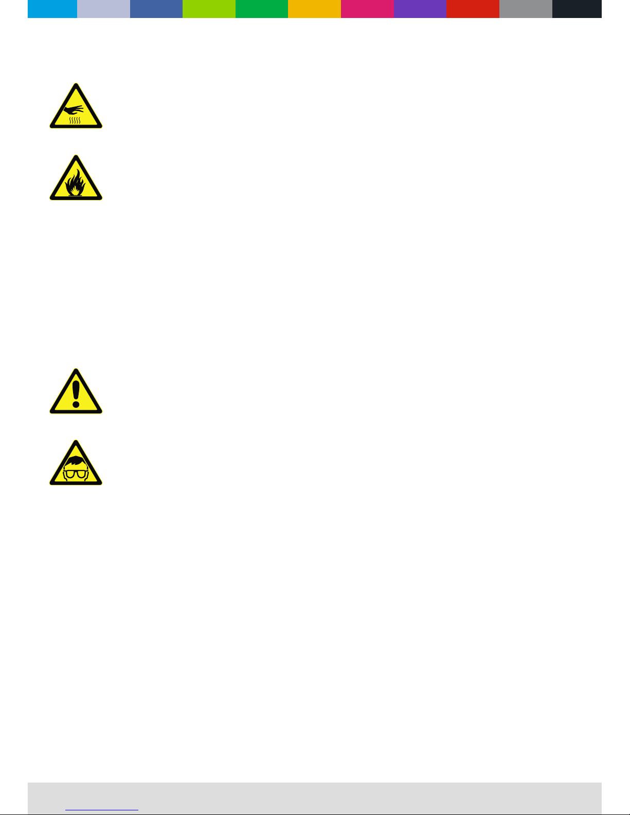
WARNING!
Fire hazard.
WARNING!
Burn hazard. Hot
surface. Do not
touch.
WARNING!
Wear protective
eyewear.
WARNING!
Refer to user
manual.
This product is for professional use only. It is not for household use.
This product presents risks of severe injury or death due to re and burn hazards, electric shock and falls.
Read this manual before installing, powering or servicing the xture, follow the safety precautions listed below and
observe all warnings in this manual and printed on the xture. If you have questions about how to operate the xture
safely, please contact your supplier.
PROTECTION FROM ELECTRIC SHOCK
• Disconnect the xture from AC power before removing or installing any cover or part and when not in use.
• Always ground (earth) the xture electrically.
• Use only a source of AC power that complies with local building and electrical codes and has both overload and
ground-fault (earth-fault) protection.
• Before using the xture, check that all power distribution equipment and cables are in perfect condition and rated
for the current requirements of all connected devices.
• Power input and throughput cables must be rated 20 A minimum, have three conductors 1.5 mm² (16 AWG)
minimum conductor size and an outer cable diameter of 5 - 15 mm. Cables must be hard usage type (SJT or
equivalent) and heat-resistant to 90° C minimum.
• Use only PowerCON TRUE 1
®
cable connectors to connect to power input sockets. Use only PowerCON TRUE 1
®
cable connectors to connect to power through put sockets.
• Isolate the xture from power immediately if the power plug or any seal, cover, cable, or other component is
damaged, defective, deformed, wet or showing signs of overheating. Do not reapply power until repairs have been
completed.
• Refer any service operation not described in this manual to a qualied technician.
• Socket outlets used to supply xture xtures with power or external power switches must be located near the
xtures and easily accessible so that the xtures can easily be disconnected from power.
WWW.CLF-LIGHTING.COM
3
PROTECTION FROM BURNS AND FIRE
• The exterior of the xture becomes hot during use. Avoid contact by persons and materials.
Allow the xture to cool for at least 5 minutes before handling.
• Keep all combustible materials (e.g. fabric, wood, paper) at least 1 metres away from the xture.
• Keep ammable materials well away from the xture.
• Ensure that there is free and unobstructed airow around the xture.
• Do not illuminate surfaces within 12 metres of the xture.
• Do not attempt to bypass thermostatic switches or fuses.
• If you relay power from one xture to another using power throughput sockets, do not connect more than ten
xture xtures in total to each other in an interconnected chain.
• Connect only other xture xtures to xture power throughput sockets.
• Do not connect any other type of device to these sockets.
• Do not stick lters, masks or other materials onto any optical component.
• Do not modify the xture in any way not described in this manual.
PROTECTION FROM INJURY
• Fasten the xture securely to a xed surface or structure when in use. The xture is not portable when installed.
• Ensure that any supporting structure and/or hardware used can hold at least 10 times the weight of all the devices
they support.
• Allow enough clearance around the head to ensure that it cannot collide with an object or another xture when it
moves.
• Check that all external covers and rigging hardware are securely fastened.
• Block access below the work area and work from a stable platform whenever installing, servicing or moving the
xture.
• Do not operate the xture with missing or damaged covers, shields or any optical component.
WWW.CLF-LIGHTING.COM
4
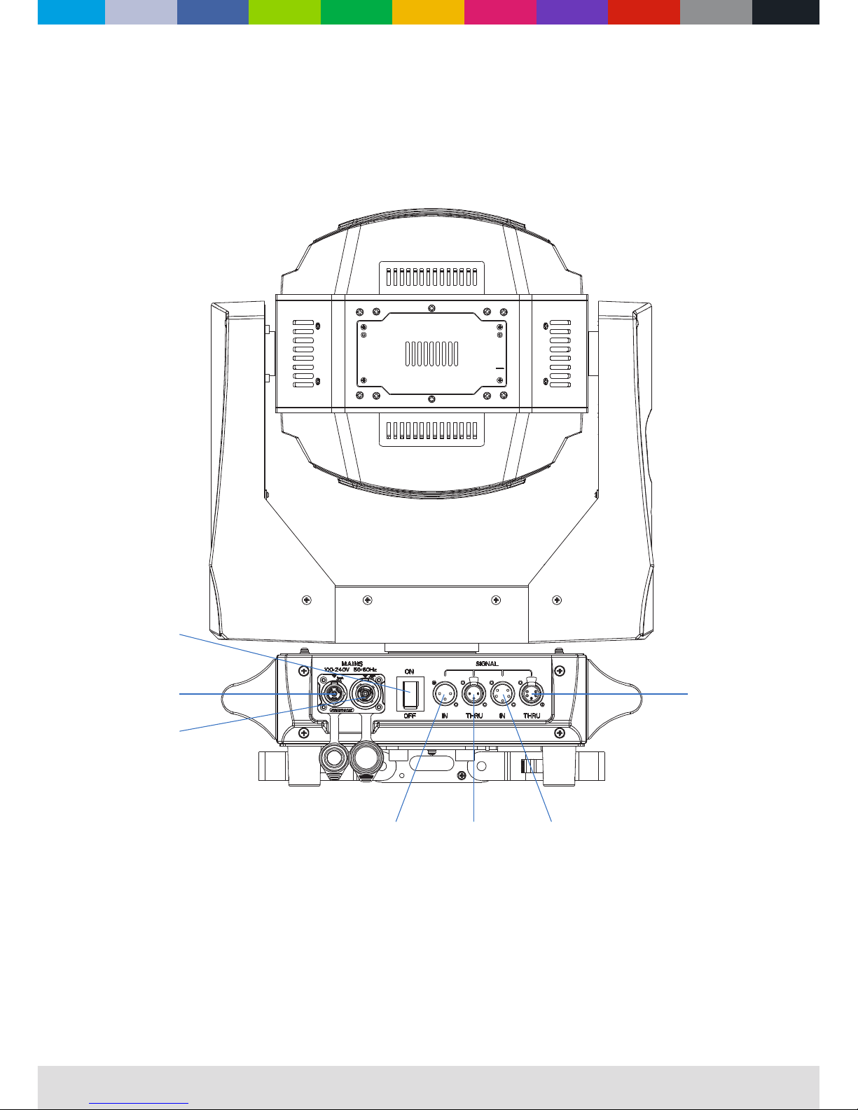
Fixture overview
AC MAINS POWER INPUT
main switch
AC MAINS POWER OUTPUT
3P DMX INPUT 5P DMX INPUT
5P DMX OUTPUT
3P DMX INPUT
WWW.CLF-LIGHTING.COM
5
Introduction
feature packed
hybrid luminaire
■ CMY Color Mixing System
■ Fixed Color Wheel
■ 2 Gobo Wheels
■ 3 + 1 Double Wheel Prisms
■ 2 Level Frost Eect
■ Zoom 2° - 42°
■ Eect wheel
Using for the rst time
Warning! Read “Safety Information” before installing, powering, operating or servicing the xture. Before applying power to the
xture:
Check that the local AC mains power source is within the xture’s power voltage and frequency ranges.
See “Power cables and power plug” on page 6. Install a PowerCON TRUE 1 ® power input connector power cable.
AC Power
Warning! Read “Safety Information” starting on before connecting the xtures to AC mains power.
Warning! For protection from electric shock, the xture must be grounded (earthed). The power
distributioncircuit must be equipped with a fuse or circuit breaker and ground-fault (earth-fault) protection.
Warning! Socket outlets or external power switches used to supply the xture with power must be located near
the xture and easily accessible so that the xtures can easily be disconnected from power.
Important! Do not insert or remove live PowerCON TRUE 1 ® connectors to apply or cut power, as this may
cause arcing at the terminals that will damage the connectors.
Important! Do not use an external dimming system to supply power to the xture, as this may cause damage to
the xture that is not covered by the product warranty.
The xture can be hard-wired to a electrical installation if you want to install it permanently, or a power plug that is
suitable for the local power outlets can be installed on the power cable.
Power voltage
Warning! Check that the voltage range specied on the xture serial number label matches the local AC mains power
voltage before applying power to the xture.
The xtures accepts AC mains power at 100-240 V nominal, 50/60 Hz. Do not apply AC mains power to the xture at any
other voltage than specied.

WWW.CLF-LIGHTING.COM
6
Power cables
Power input and throughput cables must be rated 16A minimum, have three conductors 1.5 mm² (16 AWG) minimum conductor size and
an outer cable diameter of 5 - 15 mm. Cables must be hard usage type (SJT or equivalent) and heat- resistant to 90°C minimum. In the
EU the cable must be HAR approved or equivalent.
If you install a power plug on the power cable, install a grounding-type (earthed) plug that is rated 16A minimum. Follow the plug
manufacturer’s instructions. Table 1 shows standard wire color-coding schemes and some possible pin identication schemes; if pins are
not clearly identied.
Data link
A DMX 512 data link is required in order to control a xture via DMX. The xture has 5-pin XLR connectors for DMX data input and output.
The pin-out on all connectors is pin 1 = shield, pin 2 = cold (-), and pin 3 = hot (+) Pins 4 and 5 in the 5-pin XLR connectors are not used.
Tips for reliable data transmission
To connect the xture to data:
1. Connect the DMX data output from the controller to the 5-pin XLR connector of the nearest xture.
2. Connect the DMX output of the xture closest to the controller to the DMX input of the next xture and continue connecting xtures
output to input.
Relaying power to other devices
Warning! Do not connect more than ve xtures in total to AC mains power in one interconnected chain. Power can be relayed to another
device via the PowerCON TRUE 1 ® throughput socket.
If you daisy chain the xtures in a chain so that they all draw AC mains power via the rst xture, certain points must be respected:
A heavy duty, three-conductor, 16 AWG or 1.5 mm2 cable with SJT or equivalent cable jacket must be used to connect the rst xture to
AC mains power.
• PowerCON TRUE 1 ® connectors must be used to draw AC mains power from the xtures power throughput sockets and yellow
PowerCON TRUE 1 ® connectors must be used to supply power at the xture’s power input sockets.
• No matter what the AC mains power voltage is, do not connect more than the xture in total ( including the rst xture) to AC mains
power in one interconnected daisy chain using power input and through out connectors.
Wire Color (EU models) Wire Color (US models) Conductor Symbol
Brown Black Live L
Blue White Neutral N
Yellow/Green Green Ground (earth) or
Table 1 : Wire color-coding and power connections

WWW.CLF-LIGHTING.COM
7
Physical installation
Warning! The xture must be either fastened to a at surface such as a stage or wall, or clamped to a truss or
similar structure in any orientation using a rigging clamp.
Warning! If the xture can cause injury or damage if it falls, attach an approved safety cable to one of the safety cable
attachment points on the base (see “Fixture overview”).
Check that all surfaces to be illuminated are minimum 12 metres. from the xture, that combustible materials
(wood, fabric, paper, etc.) are minimum 1 metres. from the xture, that there is free airow around the xture
and that there are no ammable materials nearby.
Fastening the xture to a at surface
The xture can be fastened to a xed at surface that is oriented at any angle. Check that the surface can
support at least 10 times the weight of all xtures and equipment to be installed on it.
Warning! The supporting surface must be hard and at or cooling may be blocked, which will cause overheating.
Fasten the xture securely. Do not stand it on a surface or leave it where it can be moved or can fall over. Attach a
securely anchored safety cable to the safety cable attachment point (see “Fixture overview”) if the xture is
to be installed in any location where it may fall and cause injury or damage if the primary attachment fails.
1. Block access under the work area. Working from a stable platform, hang the xture on the truss with the
arrow on the base towards the area to be illuminated. Tighten the rigging clamp.
2. Secure the xture against clamp failure with a secondary attachment such as an approved safety cable
that is rated for the weight of the xture using one of the attachment points at the edges of the base (see
“Fixture overview”). Do not use any other part of the xture as a safety cable attachment point.
 Loading...