

CLF LED WASH RGBW XL User Manual
WWW.CLF-LIGHTING.COM
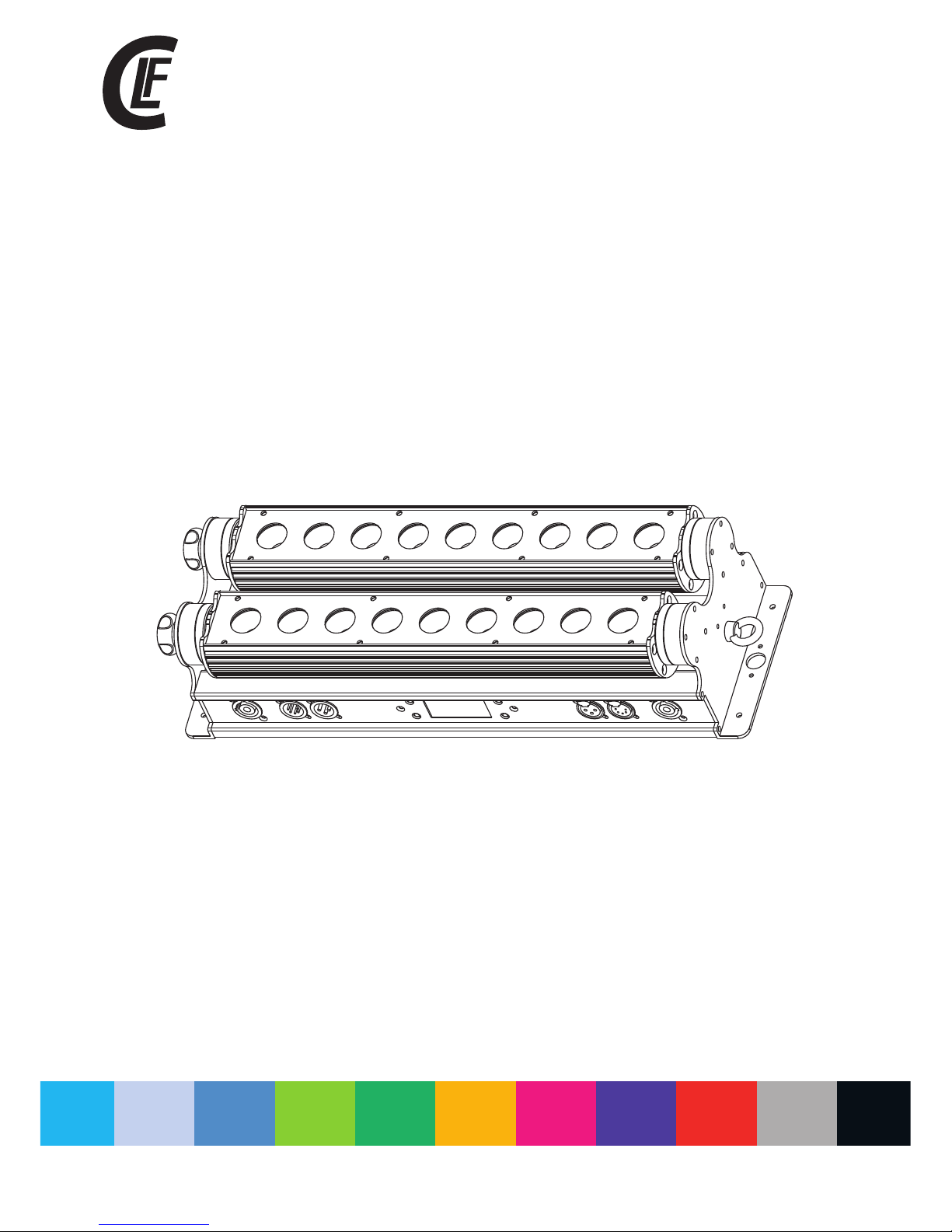
manual
LED WASH RGBW XL
V1.0 2017JANUARY

table of CONTENTS
WWW.CLF-LIGHTING.COM
Dimensions
1
Safety Information
2
Fixture overview
4
Introduction
5
AC power
5
Power voltage
5
Power cables
5
Relaying power to other devices
6
Data link
6
Tips for reliable data transmission
6
Physical installation
7
Fastening the fixtur e to a f la t su rf ac e
7
Setup
8
Control panel and menu navigation
8
DMX address setting
8
Control Mode
8
Static Color options
9
Auto Show
9
Master / Slave
9
ID Address Instructio ns
10
Setting
12
Custom program
12
Lock
12
DMX protocols
13
Onboard control menus
18
Blow-out Diagram
19
Specifications
20
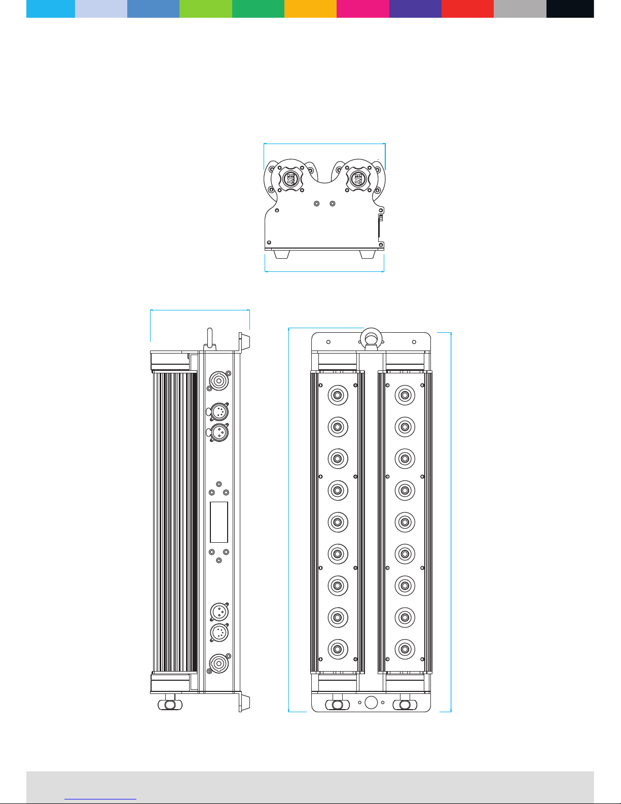
Dimensions
All dimensions are in millimeters
WWW.CLF-LIGHTING.COM
1.0
153
125
150
483
478
WWW.CLF-LIGHTING.COM
2.0
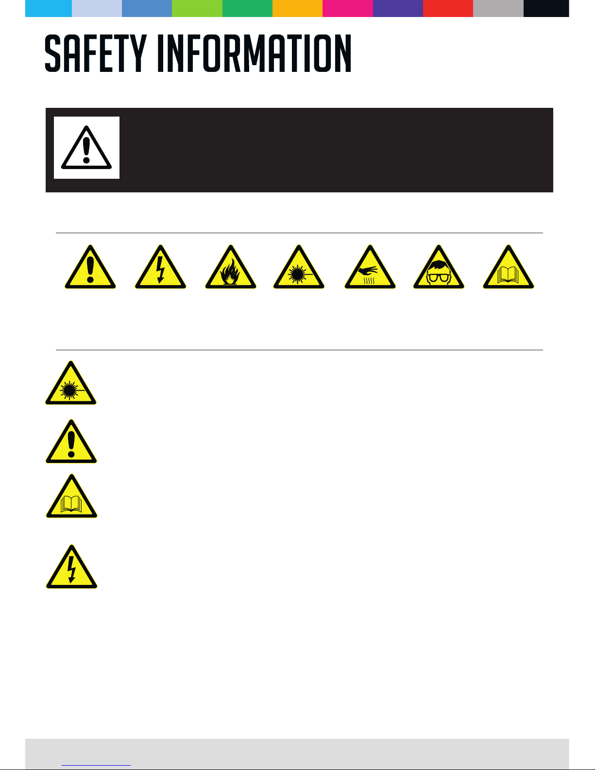
The followi ng symbols are use d to identify impo rtant safety information on the product and in this manual:
WARNING!
Read the safety precautions in this section before
installing, powering, operating or servicing this
product
DANGER!
Safety ha za rd.
Risk of sev er e
injury or d ea th.
DANGER!
Hazardo us
voltage . Ri sk of
lethal or s ev ere
electri c sh ock.
WAR NING!
Fire haza rd .
WAR NING!
LED light
emissio n. R isk of
eye injur y.
WAR NING!
Burn haza rd . Hot
surface . Do n ot
touch.
WAR NING!
Wear pr ot ective
eyewear .
WAR NING!
Refer to us er
manual.
Warning! Risk Group 3 (high risk) LED product according to EN 62471. Do not look into the beam at a distance
of less than 3 meters from the front surface of the product. Do not view the light output with optical instruments
or any device that may concentrate the beam.
Disconnect the fixture from AC power before removing or installing any cover or part and when not in use.
Always ground (earth) the fixture electrically.
Use only a source of AC power that complies with local building and electrical codes and has both overload and
ground-fault (earth-fault) protection.
Before using the fixture, check that all power distribution equipment and cables are in perfect condition and rated for
the current requirements of all connected devices.
Power input and through out cables must be rated 20A minimum, have three conductors 1.5 mm² (16 AWG) minimum
conductor size and an outer cable diameter of 5 - 15 mm . Cables must be hard usage type (SJT or equivalent) and
heat-resistant to 90° C minimum.
Use only cable connectors to connect to power input sockets. Use only cable connectors
to connect to power through put sockets.
Isolate the fixture from power immediately if the power plug or any seal, cover, cable, or other component is
damaged, defective, deformed, wet or showing signs of overheating. Do not reapply power until repairs have been
completed.
This product is for professional use only. It is not for household use.
This product presents risks of severe injury or death due to fire and burn hazards, electric shock and falls.
Read this manual before installing, powering or servicing the fixture, follow the safety precautions listed below and
observe all warnings in this manual and printed on the fixture. If you have questions about how to operate the fixture
safely, please contact your supplier.
PROTECTION FROM ELECTRIC SHOCK
l
l
l
l
l
l
l
® ®
PowerCON PowerCON
WWW.CLF-LIGHTING.COM
3.0
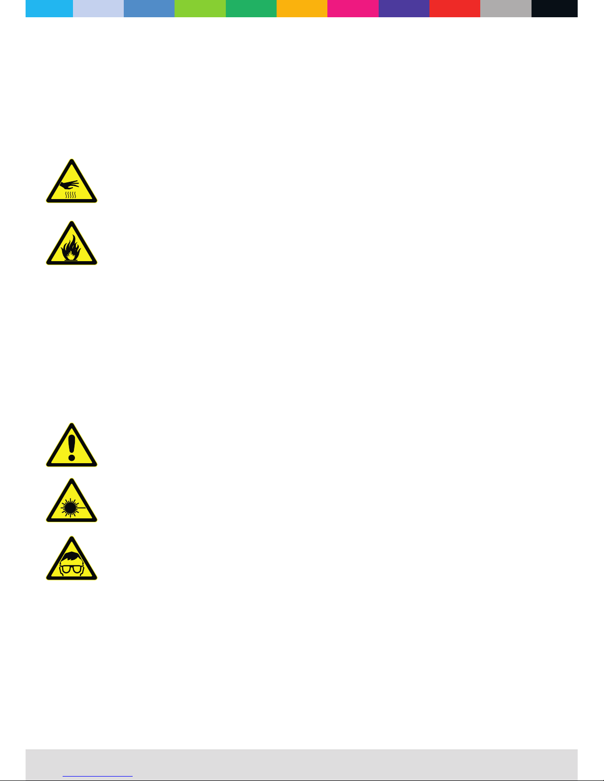
Do not expose the fixture to rain or moisture
Refer any service operation not described in this manual to a qualified technician.
Socket outlets used to supply the fixture with power or external power switches must be located near the fixtures and
easily accessible so that the fixtures can easily be disconnected from power.
Do not operate the fixture if the ambient temperature (Ta) exceeds 40°C.
The exterior of the fixture becomes hot during use. Avoid contact by persons and materials.
Allow the fixture to cool for at least 10 minutes before handling.
Keep all combustible materials (e.g. fabric, wood, paper) at least 100 mm away from the fixture.
Keep flammable materials well away from the fixture.
Ensure that there is free and unobstructed airflow around the fixture.
Do not illuminate surfaces within 200 mm of the fixture.
Do not attempt to bypass thermostatic switches or fuses.
If you relay power from one fixture to another using power throughput sockets, do not connect more than ten the
fixture in total to each other in an interconnected chain.
Connect only other the fixture to fixture power throughput sockets. Do not connect any other type of device to these
sockets.
Do not stick filters, masks or other materials onto any optical component.
Do not modify the fixture in any way not described in this manual
Do not use fixture on a dimmer
Do not look continuously at LEDs from a distance of less than 3 meters from the front surface of the fixture without
protective eyewear such as shade 4-5 welding goggles. At less than this distance, the LED emission can cause eye
injury or irritation. At distances of 3 meters and above, light output is harmless to the naked eye provided that the
eye’s natural aversion response is not overcome.
Do not look at LEDs with magnifiers, telescopes, binoculars or similar optical instruments that may concentrate the
light output.
Ensure that persons are not looking at the LEDs from within 3 meters when the product lights up suddenly. This can
happen when power is applied, when the product receives a DMX signal, or when SERVICE menu items are
selected.
Fasten the fixture securely to a fixed surface or structure when in use.
Ensure that any supporting structure and/or hardware used can hold at least 10 times the weight of all the devices
they support.
Allow enough clearance around the fixture to ensure that it cannot collide with an object or another fixture when it
moves.
Check that all external covers and rigging hardware are securely fastened.
Block access below the work area and work from a stable platform whenever installing, servicing or moving the
fixture.
Do not operate the fixture with missing or damaged covers, shields or any optical component.
l
l
l
l
l
l
l
l
l
l
l
l
l
l
l
l
l
l
l
l
l
l
l
l
PROTECTION FROM BURNS AND FIRE
PROTECTION FROM INJURY
Do not connect any other type of device to these sockets.
WWW.CLF-LIGHTING.COM
4.0
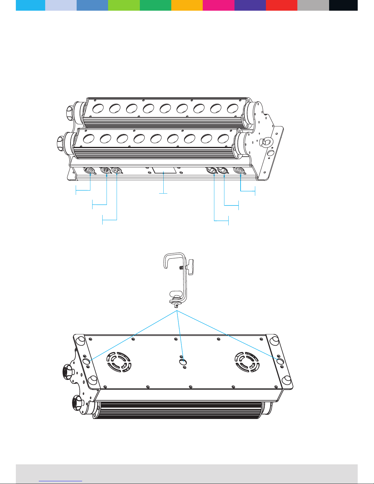
fixture overview
G Clamp with
Quicklock # 875760
(Optional)
5PIN D MX IN
5PIN D MX OUT
3PIN D MX IN
3PIN D MX OUT
MAIN S IN
MAIN S OUT
Disp lay
WWW.CLF-LIGHTING.COM
5.0
Introduction
Warning! Read “Safety Information” on page 2 before installing, powering, operating or servicing the fixture.
Before applying power to the fixture:
Check that the local AC mains power source is within the fixture’s power voltage and frequency ranges.
See “Power cables and power plug” on page 6. Install a power input connector on a suitable power
cable.
l
l
®
PowerCON
Using for the first time
This compact LED-based wallwasher features:
RGBW color control with color temperature control
Onboard control panel and LED graphic display
Each line can be control independently
nSuperior Color mixing via unique lens design
nExceptionally smooth projection
n
n
n
n
n
n
User defined program/ inner optional program
LED display with p as sw or d pr ot ec ti on
5 distinct dimming curves
AC power
War ni ng! Read “Safety Information” starting on page 2 before connecting the fixtures to AC mains power.
War ning! For protection from electric shock, the fixture must be grounded (earthed). The power
distributioncircuit must be equipped with a fuse or circuit breaker and ground-fault (earth-fault) protection.
War ning! Socket outlets or external power switches used to supply the fixture with power must be
located near the fixture and easily acce ssible so that the fixtures can easily be disconnected from power.
Important! Do not insert o r re mo ve l iv e connectors to apply or cut p ow er, a s th is m ay
cause arcingat the t er mi na ls t ha t wi ll d am ag e th e co nn ec to rs .
Important! Do not use an e xt er na l di mm in g sy st em t o su pp ly p ow er t o th e fi xture, as this may cause
damage to the fixture th at i s no t co ve re d by t he p ro du ct w ar ra nt y.
The fixture can be har d- wi re d to a e le ct ri ca l in st al la tion if you want to install it permanently, or a po we r pl ug
that is suitable for t he l oc al p ow er o ut le ts c an b e in st al led on the power cable.
power voltage
War ni ng ! Check that the voltage range specified on the fixtures serial number label matches the local
AC mains power vol ta ge b ef or e ap pl yi ng p ow er t o th e fi xt ure.
The fixtures accep ts AC m ai ns p ow er a t 10 0- 24 0 V no mi na l, 5 0/60 Hz. Do not apply AC mains power to the
fixture at any other v ol ta ge t ha n sp ec if ie d.
®
PowerCON
WWW.CLF-LIGHTING.COM
6.0
power cables
Power input and thro ug hp ut c ab le s mu st b e ra te d 20 A min imum, have three conductors 1.5 mm² (16 AWG)
minimum conduc to r si ze a nd a n ou te r ca bl e di am et er o f 5 - 15 m m. Cables must be hard usage type (SJT or
equivalent) an d he at - re si st an t to 9 0° C mi ni mu m. I n th e EU t he cable must be HAR approved or equivalent.
If you install a power p lu g on t he p ow er c ab le , in st al l a gr ou nding-type (earthed) plug that is rated 20A
minimum. Follow th e pl ug m an uf ac tu re r’s instructions. Table 1 shows standard wire color-coding schemes
and some possibl e pi n id en ti fi ca ti on s ch em es ; if p in s are not clearly identified.
Relaying power to other devices
War ni ng ! Do not connect more than ten fixtures in total to AC mains power in one interconnected chain.
Power can be relay ed t o an ot he r de vi ce v ia t he throughput socke t.
If you daisy chain the f ix tu re s in a c ha in s o th at t he y al l dr aw AC m ains power via the first fixture, certain
points must be respe ct ed :
2
• A heavy duty, thr ee -c on du ct or, 1 6 AWG or 1.5 mm cable with SJT or equivalent cable jacket must be used to
connect the first fixt ur e to AC m ai ns p ow er.
• connectors must be used to draw AC mains power from the fixtures power throughput sockets and
yellow connectors must be used to supply power at the fixture’s power input sockets.
• No matter what the AC mai ns p ow er v ol ta ge i s, d o no t co nn ec t mo re than ten the fixture in total (i.e.
including the fi rs t fi xt ur e) t o AC ma in s po we r in o ne i nt er connected daisy chain using power input and through
out connectors.
®
PowerCON
®
PowerCON
®
PowerCON
A DMX 512 data link is re qu ir ed i n or de r to c on tr ol a f ix tu re v ia D MX. The fixt ur e ha s 3 & 5- pi n XL R co nn ec to rs
for DMX data input and o ut pu t. The pin-out on all connectors is pin 1 = shie ld , pi n 2 = co ld ( -) , an d pi n 3 = ho t
(+) Pins 4 and 5 in the 5-pi n XL R co nn ec to rs a re n ot u se d.
tips for reliable data transmission
To connect the fixture t o da ta :
1. Connect the DMX data output from the cont roller to 3 or
2. Connect the DMX out pu t of t he f ix tu re c lo se st t o th e co nt ro ll er to the DMX input of the next fixture and
continue conne ct in g fi xt ur es o ut pu t to i np ut .
5-pin XLR connec to r of t he n ea re st f ix tu re .
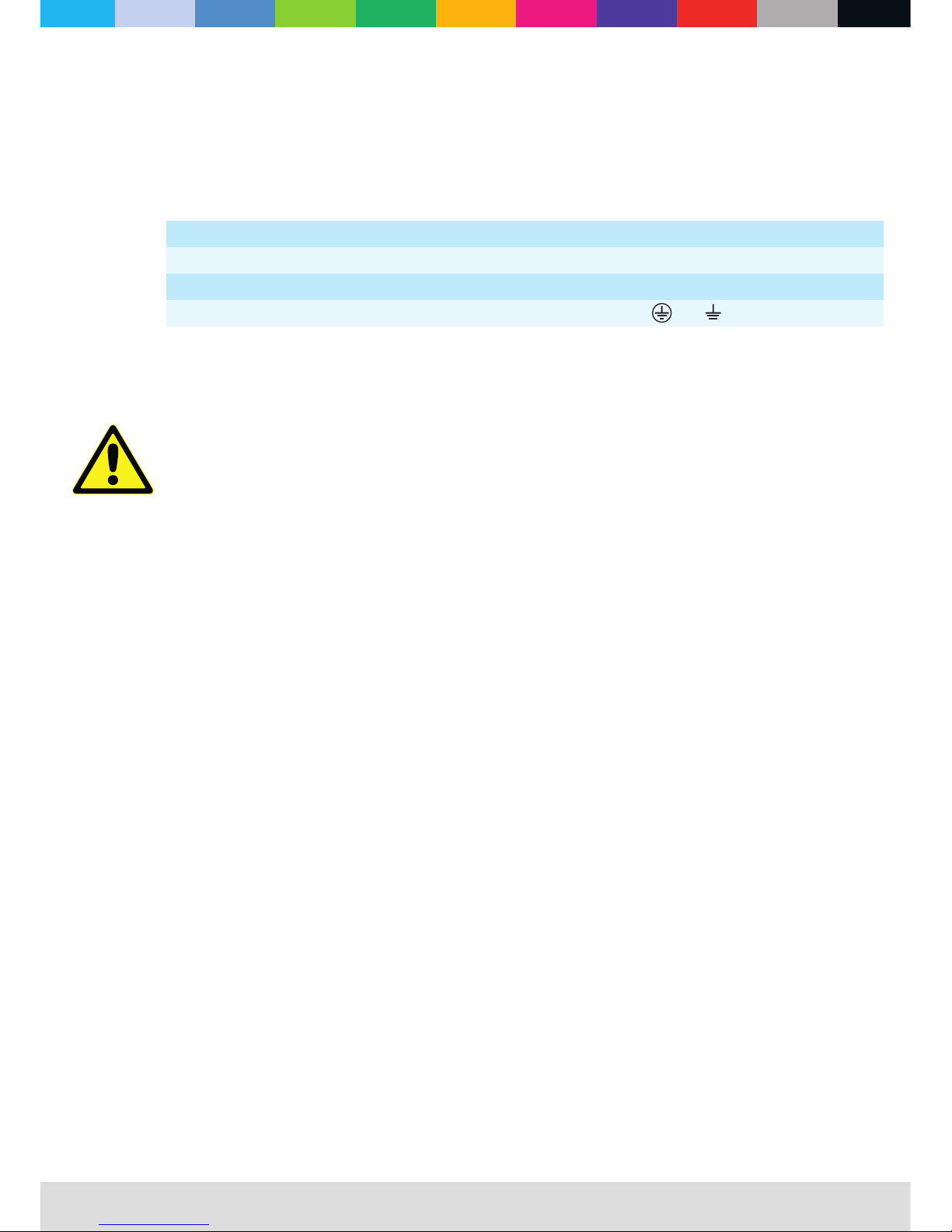
Wire Color (EU models)
Wire Color (US models)
Conductor
Symbol
Screw (US)
Brown
Black
Live
L
Yellow or Brass
Blue
White
Neutral
N
Silver
Yellow/Green
Green
Ground (earth)
or
Green
DATA LINK
Table 1 : Wire color-coding and power connections
 Loading...