

Page 1
manual
V2.0 AUGUST 2017WWW.CLF-LIGHTING.COM
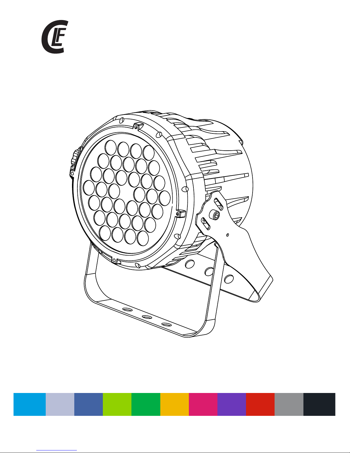
dynamic white par
Page 2
WWW.CLF-LIGHTING.COM
Dimensions 1
Safety information 2
Fixture overview 4
Introduction 5
AC power 5
Power voltage 5
Power cables 6
Relaying power to other devices 6
Data link 6
Tips for reliable data transmission 6
Physical installation 7
Setup 8
Control panel and menu navigation 8
DMX address setting 8
Control mode 8
Menu navigation 9
DMX protocols 10
Specications 12
Blow-out diagram 13
table of CONTENTS
Page 3
WWW.CLF-LIGHTING.COM
1.0
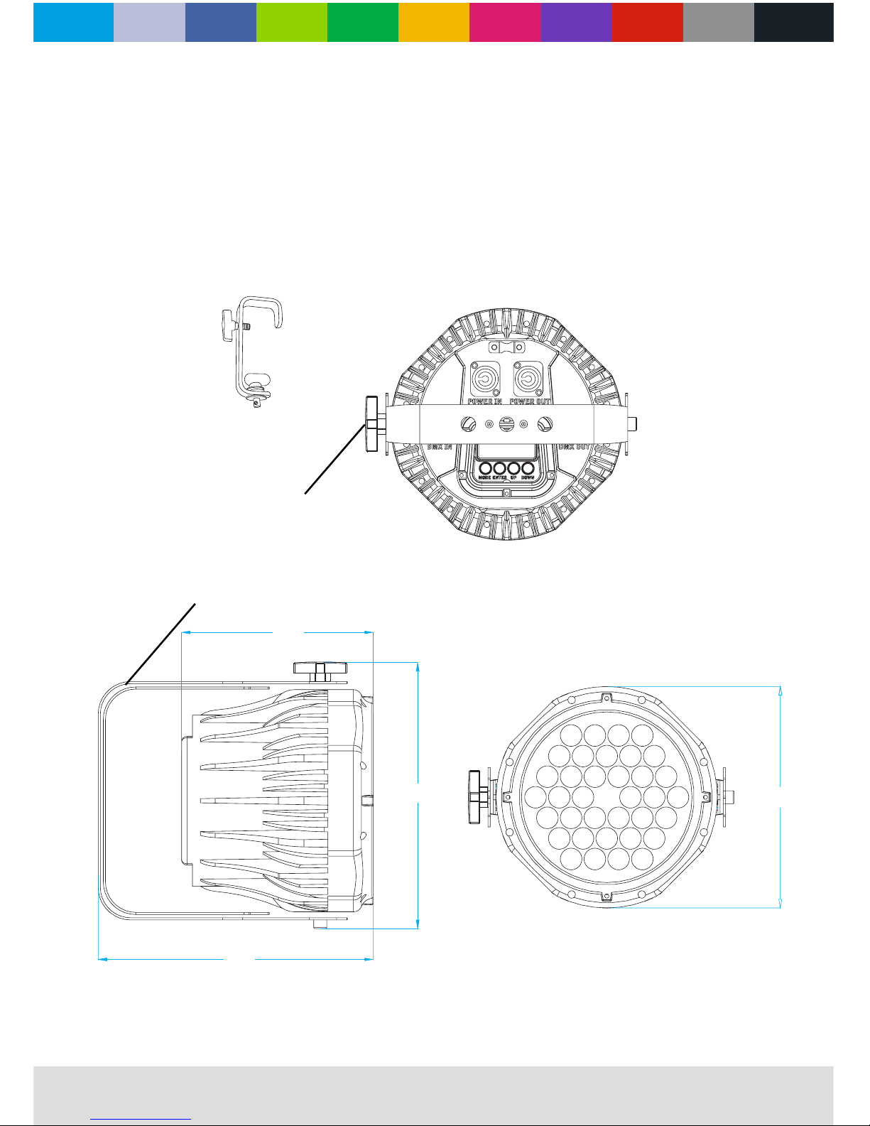
Dimensions
All dimensions are in millimeters
207
G Clamp with
Quicklock #875760
(Optional)
153
150
G Clamp with
Quicklock #875760
(Optional)
278
207
483
125
205
255
177
300
G Clamp with
Quicklock #875760
(Optional)
158
HANGING BRACKET / FLOOR STAND
BRACKET ADJUSTMENT KNOB
Page 4
WWW.CLF-LIGHTING.COM
Safety Information
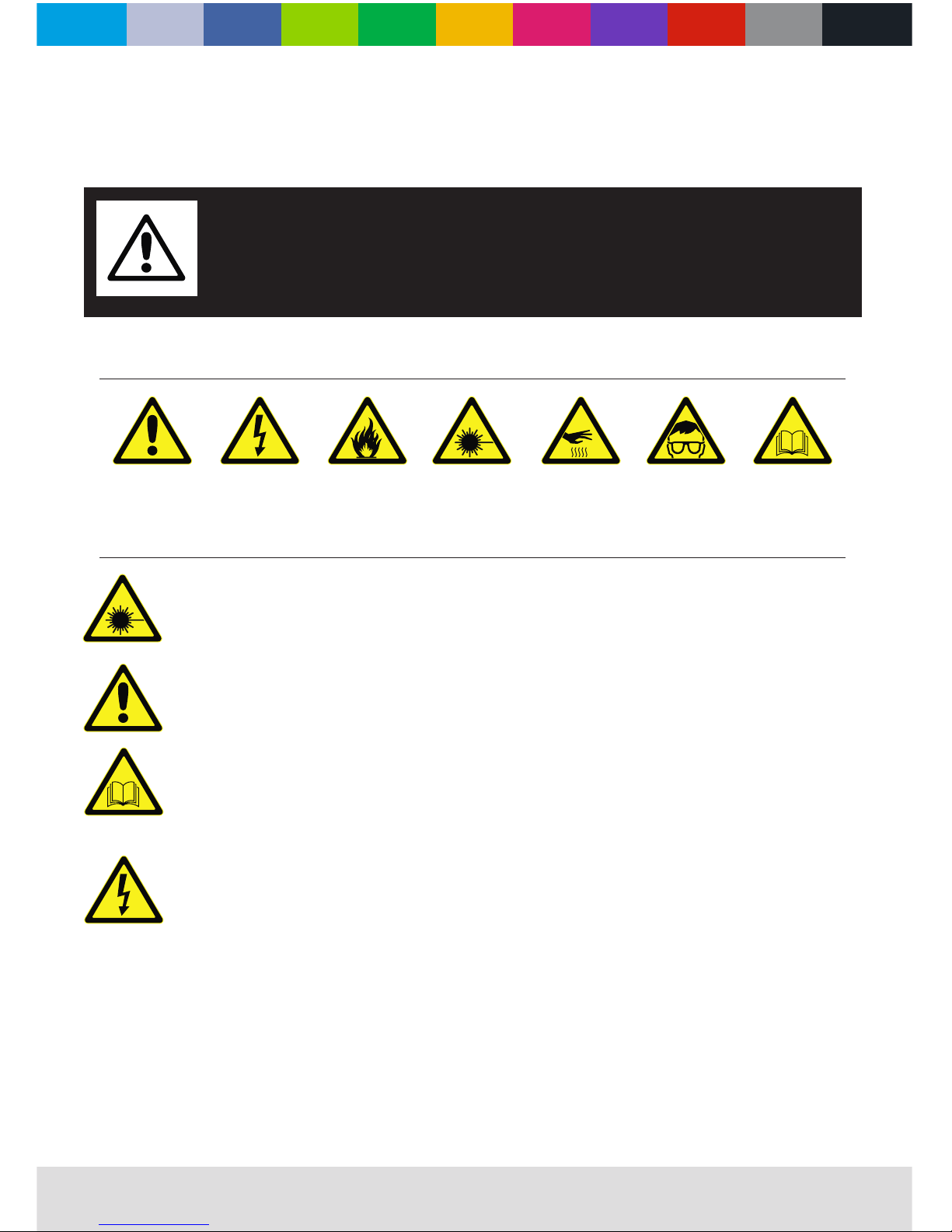
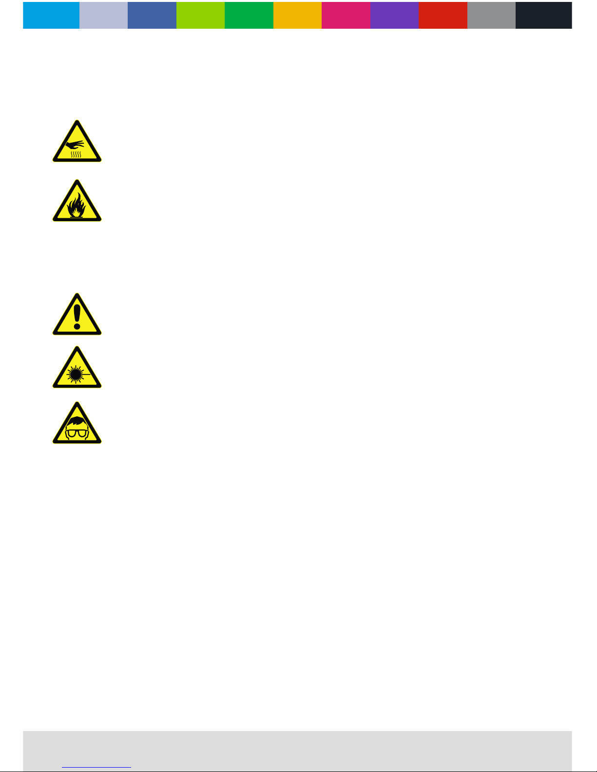
The following symbols ar e us ed t o id en ti fy i mp or ta nt s af et y in fo rm at io n on t he p roduct and in this manual:
WARNING!
Read the safety precautions in this section before
installing, powering, operating or servicing this
product
DANGE R!
Safet y hazar d.
Risk of s evere
injur y or deat h.
DANGE R!
Hazar dous
volta ge. Ris k of
letha l or seve re
elect ric sho ck.
WAR NING!
Fire ha zard.
WAR NING!
LED lig ht
emiss ion. Ri sk of
eye inj ury.
WAR NING!
Burn ha zard. H ot
surfa ce. Do no t
touch .
WAR NING!
Wear pr ote ctive
eyewe ar.
WAR NING!
Refer t o user
m
anual .
Warning! Risk Group 3 (high risk) LED product according to EN 62471. Do not look into the beam at a distance
of less than 8.3 meters from the front surface of the product. Do not view the light output with optical
instruments or any device that may concentrate the beam.
This product is for professional use only. It is not for household use.
This product presents risks of severe injury or death due to fire and burn hazards, electric shock and falls.
Read this manual before installing, powering or servicing the fixture, follow the safety precautions listed below and
observe all warnings in this manual and printed on the fixture. If you have questions about how to operate the fixture
safely, please contact your supplier.
PROTECTION FROM ELECTRIC SHOCK
Disconnect the fixture from AC power before removing or installing any cover or part and when not in use.
Always ground (earth) the fixture electrically.
Use only a source of AC power that complies with local building and electrical codes and has both overload and
ground-fault (earth-fault) protection.
Before using the fixture, check that all power distribution equipment and cables are in perfect condition and rated for
the current requirements of all connected devices.
Power input and throughput cables must be rated 20 A minimum, have three conductors 1.5 mm² (16 AWG) minimum
conductor size and an outer cable diameter of 5 - 15 mm . Cables must be hard usage type (SJT or equivalent) and
heat-resistant to 90° C minimum.
Use only powerCON cable connectors to connect to power input sockets. Use only powerCON cable connectors to
connect to power through put sockets.
Isolate the fixture from power immediately if the power plug or any seal, cover, cable, or other component is
damaged, defective, deformed, wet or showing signs of overheating. Do not reapply power until repairs have been
completed.
2.0
Page 5
WWW.CLF-LIGHTING.COM
Do not expose the xture to rain or moisture
• Refer any service operation not described in this manual to a qualied technician.
• Socket outlets used to supply xture xtures with power or external power switches must be located near the xtures
and easily accessible so that the xtures can easily be disconnected from power.
PROTECTION FROM BURNS AND FIRE
• Do not operate the xture if the ambient temperature (Ta) exceeds 40° C .
• The exterior of the xture becomes hot during use. Avoid contact by persons and materials.
Allow the xture to cool for at least 5 minutes before handling.
• Keep all combustible materials (e.g. fabric, wood, paper) at least 100 mm away from the xture.
• Keep ammable materials well away from the xture.
• Ensure that there is free and unobstructed airow around the xture.
• Do not illuminate surfaces within 200 mm of the xture.
• Do not attempt to bypass thermostatic switches or fuses.
• If you relay power from one xture to another using power throughput sockets, do not connect more than ten xture
xtures in total to each other in an interconnected chain.
• Connect only other xture xtures to xture power throughput sockets.
• Do not connect any other type of device to these sockets.
• Do not stick lters, masks or other materials onto any optical component.
• Do not modify the xture in any way not described in this manual.
PROTECTION FROM INJURY
• Do not look continuously at LEDs from a distance of less than 3 meters from the front surface of the xture without
protective eyewear such as shade 4-5 welding goggles. At less than this distance, the LED emission can cause eye
injury or irritation. At distances of 3 meters and above, light output is harmless to the naked eye provided that the
eye’s natural aversion response is not overcome.
• Do not look at LEDs with magniers, telescopes, binoculars or similar optical instruments that may concentrate the
light output.
• Ensure that persons are not looking at the LEDs from within 8.3 meters when the product lights up suddenly.
This can happen when power is applied, when the product receives a DMX signal, or when SERVICE menu items
are selected.
• Fasten the xture securely to a xed surface or structure when in use. The xture is not portable when installed.
• Ensure that any supporting structure and/or hardware used can hold at least 10 times the weight of all the devices
they support.
• Allow enough clearance around the head to ensure that it cannot collide with an object or another xture when it moves.
• Check that all external covers and rigging hardware are securely fastened.
• Block access below the work area and work from a stable platform whenever installing, servicing or moving the xture.
• Do not operate the xture with missing or damaged covers, shields or any optical component.
3.0
Page 6
WWW.CLF-LIGHTING.COM
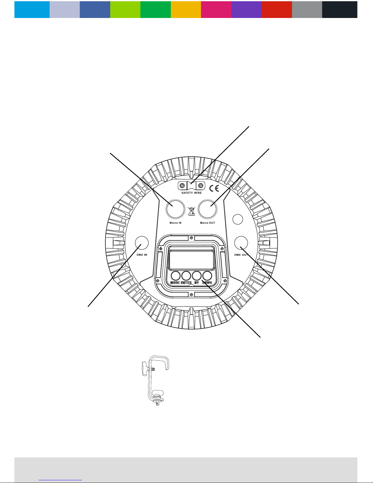
xture overview
max 10.7A
4.0
207
G Clamp with
Quicklock #875760
(Optional)
153
150
G Clamp with
Quicklock #875760
(Optional)
SAFETY
POWER OUT
DMX OUT
CONTROL BOARD
DMX IN
POWER IN
Page 7
WWW.CLF-LIGHTING.COM
introduction
ac power
Compact cold white & warm white LED xture:
• 25° beam angle
• Extensive white color temperature control (2.800K – 6.500K, CRI>90)
• Solid housing
• Double bracket for oor and truss mounting
• ‘Flicker free’ operation
• Powercon in and out
Using for the rst time
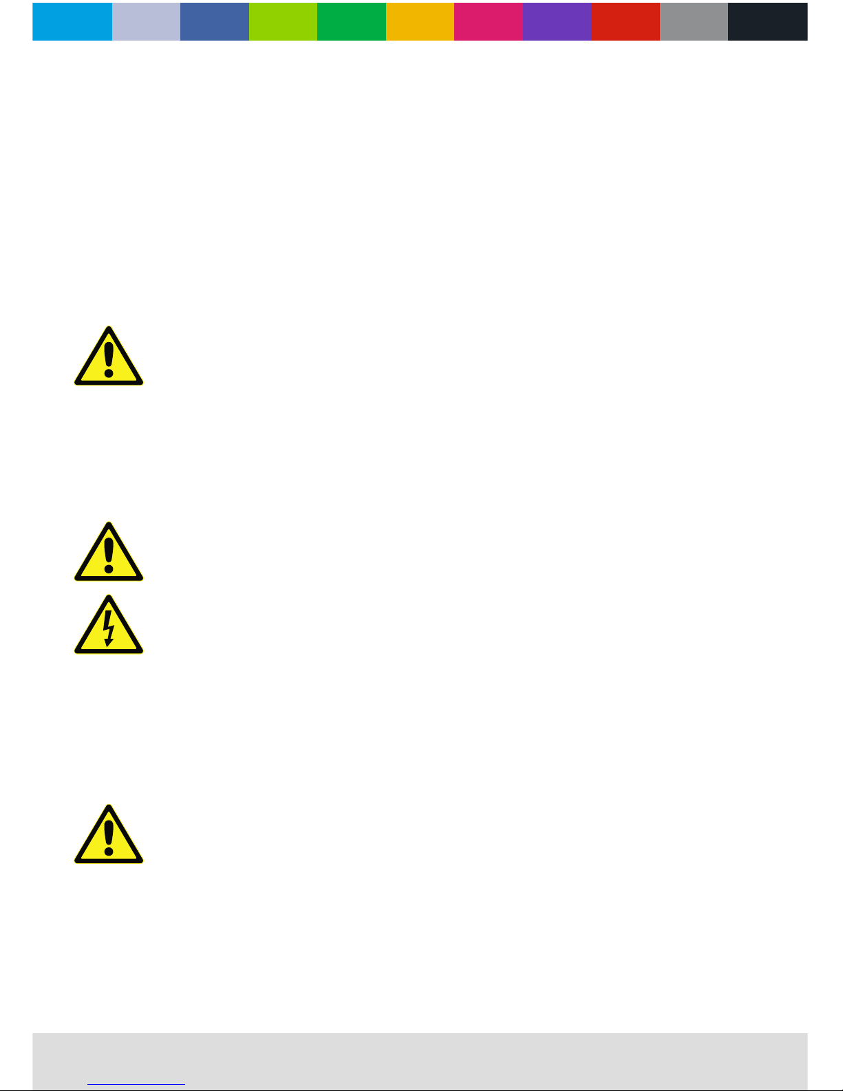
Warning! Read “Safety Information” on page 2 before installing, powering, operating or servicing the xture.
Before applying power to the xture:
• Check that the local AC mains power source is within the xture’s power voltage and frequency ranges.
• See “Power cables and power plug” on page 6. Install a powerCON power input connector on a suitable power
cable. If drawing power from a mains power outlet, install a suitable power plug on the power cable.
Warning! Read “Safety Information” starting on page 2 before connecting the xtures to AC mains power.
Warning! For protection from electric shock, the xture must be grounded (earthed). The power distribution
circuit must be equipped with a fuse or circuit breaker and ground-fault (earth-fault) protection.
Warning! Socket outlets or external power switches used to supply the xture with power must be located
near the xture and easily accessible so that the xtures can easily be disconnected from power.
Important! Do not insert or remove live powerCON connectors to apply or cut power, as this may cause
arcing at the terminals that will damage the connectors.
Important! Do not use an external dimming system to supply power to the xture, as this may cause damage
to the xture that is not covered by the product warranty.
The xture can be hard-wired to a electrical installation if you want to install it permanently, or a power plug that is
suitable for the local power outlets can be installed on the power cable.
power voltage
Warning! Check that the voltage range specied on the xtures serial number label matches the local AC
mains power voltage before applying power to the xture.
The xtures accepts AC mains power at 100-240 V nominal, 50/60 Hz. Do not apply AC mains power to the xture at
any other voltage than specied on the xture’s serial number label.
5.0
Page 8
WWW.CLF-LIGHTING.COM
power cables
Power input and throughput cables must be rated 20 A minimum, have three conductors 1.5 mm² (16 AWG) minimum
conductor size and an outer cable diameter of 5 - 15 mm. Cables must be hard usage type (SJT or equivalent) and
heat resistant to 90°C minimum. In the EU the cable must be HAR approved or equivalent.
If you install a power plug on the power cable, install a grounding-type (earthed) plug that is rated 20 A minimum.
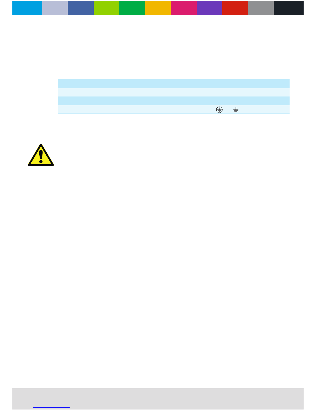
Follow the plug manufacturer’s instructions. Table 1 shows standard wire color-coding schemes and some possible
pin identication schemes; if pins are not clearly identied, or if you have any doubts.
Relaying power to other devices
Warning! Do not connect more than 8 xtures in total to AC mains power in one interconnected chain.
Power can be relayed to another device via the light-grey PowerCon throughput socket.
If you daisy chain the xtures in a chain so that they all draw AC mains power via the rst xture, certain points must be
respected:
• A heavy duty, three-conductor, 16 AWG or 1.5 mm2 cable with SJT or equivalent cable jacket must be used to
connect the rst xture to AC mains power.
• PowerCON connectors must be used to draw AC mains power from the xtures power output sockets. Blue power CON connectors must be used to supply power through the xture’s power input sockets.
A DMX 512 data link is required in order to control a xture via DMX. The xture has 3-pin XLR connectors for DMX
data input and output. The pin-out on all connectors is pin 1 = shield, pin 2 = cold (-), and pin 3 = hot (+).
tips for reliable data transmission
To connect the xture to data:
1. Connect the DMX data output from the controller to the closest xture’s male 3-pin XLR DMX input connector.
2. Connect the DMX output of the xture closest to the controller to the DMX input of the next xture and continue
connecting xtures output to input.
Wire Color (EU models) Wire Color (USmodels) Conductor Symbol Screw (US)
Brown Black Live L Yellow or Brass
Blue White Neutral N Silver
Yellow/Green Green Ground (earth) or Green
Table 1: Wire color-coding and power connections
6.0
DATA LINK
Page 9
WWW.CLF-LIGHTING.COM
Warning! The xture must be either fastened to a at surface such as a stage or wall, or clamped to a truss or
similar structure in any orientation using a rigging clamp.
Warning! If the xture can cause injury or damage it if falls, attach an approved safety cable to one of the
safety cable attachment points on the base (see “Fixture overview” on page 4).
Check that all surfaces to be illuminated are minimum 200 mm. from the xture, that combustible materials
(wood, fabric, paper, etc.) are minimum 100 mm. from the head, that there is free airow around the xture
and that there are no ammable materials nearby. Make sure that it is impossible for the moving head to
collide with another xture or other object.
Fastening the xture to a at surface
The xture can be fastened to a xed at surface that is oriented at any angle. Check that the surface can support at
least 10 times the weight of all xtures and equipment to be installed on it.
Warning! The supporting surface must be hard. Fasten the xture securely. Do not stand it on a surface or leave
it where it can be moved or can fall over. Attach a securely anchored safety cable to the safety cable attachment
point (see “Fixture overview” on page 4) if the xture is to be installed in any location where it may fall and
cause injury or damage if the primary attachment fails.
1. Block access under the work area. Working from a stable platform, hang the xture on the truss with the arrow on
the base towards the area to be illuminated. Tighten the rigging clamp.
2. Secure the xture against clamp failure with a secondary attachment such as an approved safety cable that is rated
for the weight of the xture using one of the attachment points at the edges of the base (see “Fixture overview” on page 4).
Do not use any other part of the xture as a safety cable attachment point.
7.0
Physical installation
Page 10
WWW.CLF-LIGHTING.COM
Warning! Read “Safety Information” on page 2 before installing, powering, operating or servicing the xture.
Control panel and menu navigation
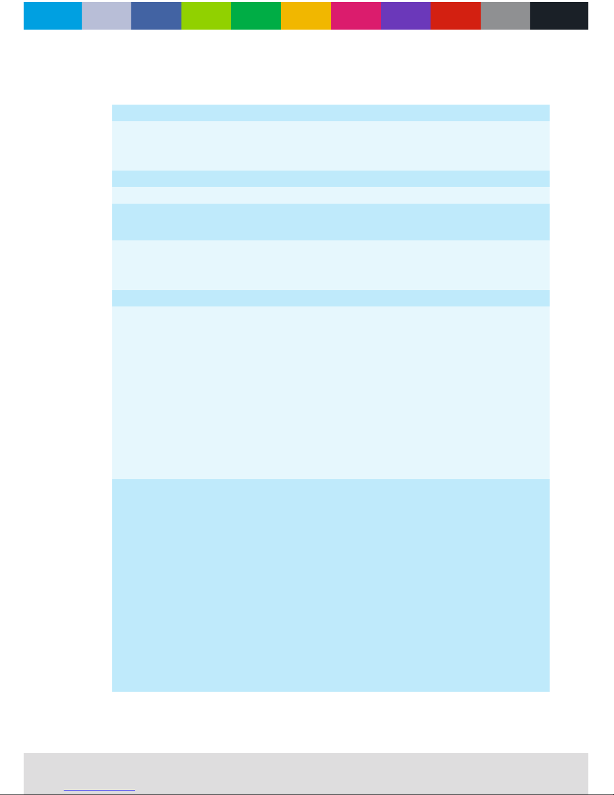
The onboard control panel and display are used to set the xture’s DMX address, congure individual xture settings
(personality), read out data and execute service utilities. See “Menu Navigation” on page 9 for a complete list of menus
and commands.
Using the control buttons
• To enter the menu select [MODE].
• Press [UP] and [DOWN] to scroll within a menu or adjust values.
• To enter a menu, select a function or apply a selection, press [ENTER].
• To escape a function or move back one level in the menu structure, press [MODE].
DMX address setting
The DMX address, also known as the start channel, is the rst channel used to receive instructions from the controller.
For independent control, each xture must be assigned its own control channels.
The DMX address is congured using the DMX address [DMX] menu in the control panel. For setting the DMX address
press [ENTER] before you can change the adddres.
• If a DMX signal is presented to the xture, a red dot is shown on the menu screen.
Control mode
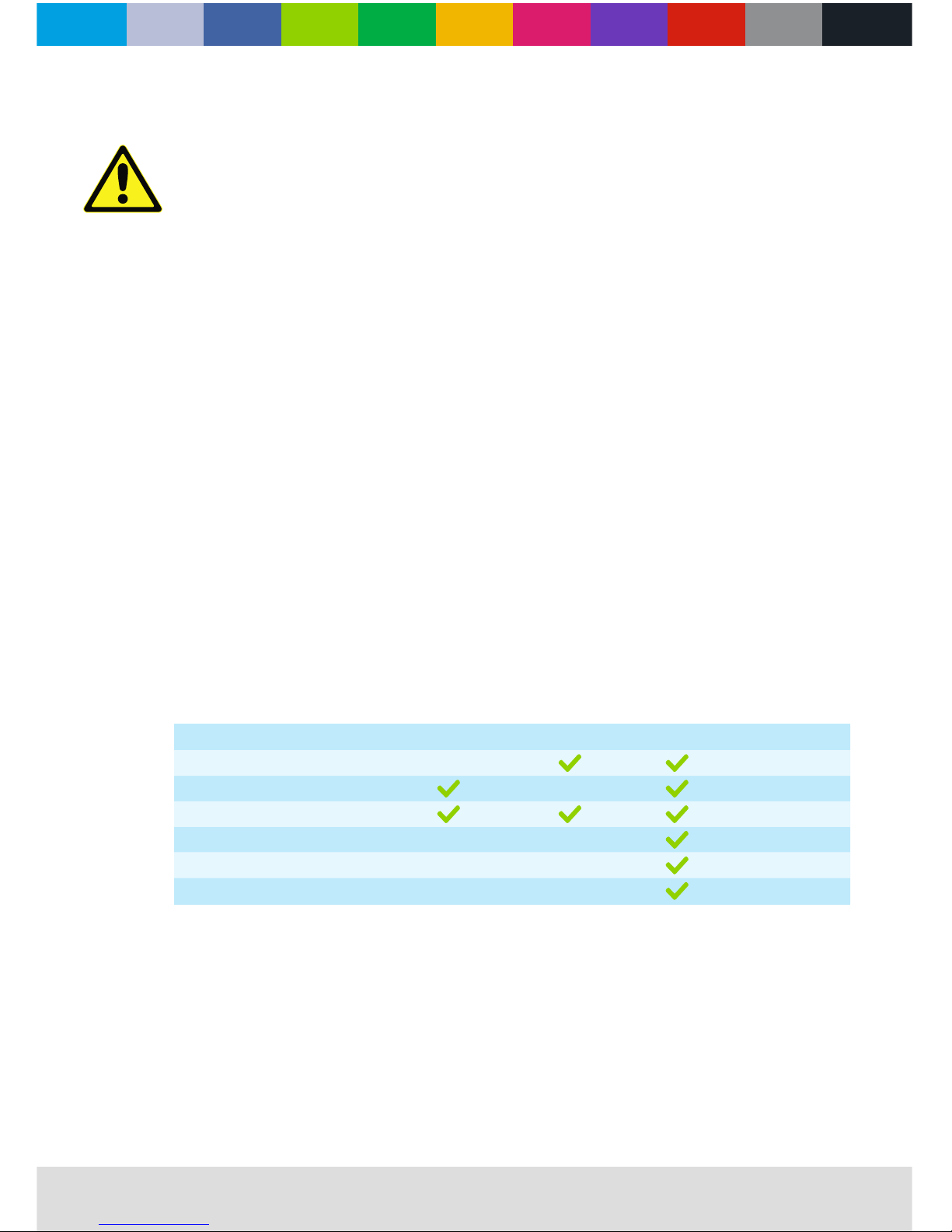
DMX control mode is selected in the control mode [PERS] menu. The xture has three DMX control modes:
2ch 3ch 7ch
Cool white & warm white
CCT
Dimming
Strobe
ID
Dimmer Speed
8.0
SETUP
Page 11
WWW.CLF-LIGHTING.COM
MAIN FUNCTION SUB FUNCTION SELECTION INSTRUCTION
STAT
C000
000 - 255
(0 - 100%)
User can combine cool white and warm white to
generate a custom color
W000
S000 00 - 20 Select strobe frequency
AUTO AT00 01 - 03 3 auto programs available
DMX D001 001 - 512 Set DMX start address
RUN
DMX
Sets the operating made for the xture to receive
signal from a DMX controller (DMX) and receive
signal from master xture (SLAVE).
SLAV
PERS
07CH 7 CHS: D + C + W
02CH 2 CHS: Dimmer + CCT
03CH 3 CHS: Dimmer + C + W
ID 01 - 66 Assign ID address for xtures
SET
IDSW
ON - OFF
Enable or disable ID
LOCK
ON - OFF
Enables or disables password lockout
Unlock with password:
(MODE, UP, MODE, DOWN, MODE, UP, MODE, DOWN)(ENTER)
DIM
OFF
‘OFF’ means select linear dimming, or choose dimmer 1 - 4 to control the dimming speed. Dimming 1
of the fastest dimming curves, 4 for the most slowly
dimming curve.
DIM 1 / 2 / 3 / 4
RESET
Password
(UP, UP, DOWN,
DOWN, ENTER)
Reset factory defaults
VER 1.31 Version number
CCT
2800
C000
Preset custom whites, to choose dierent color
temperatures.
3000
3200
3400
4200
W000
4900
5600
5900
9.0
MENU NAVIGATION
Page 12

WWW.CLF-LIGHTING.COM
02 CHANNELS VALUE DESCRIPTION
1. Dimming 000 - 255 0 - 100%
2. CCT
000 - 010 No function
011 - 040 White 1: 2800K
041 - 070 White 2: 3000K
071 - 100 White 3: 3200K
101 - 130 White 4: 3400K
131 - 160 White 5: 4200K
161 - 190 White 6: 4900K
191 - 220 White 7: 5600K
221 - 255 White 8: 5900K
dmx protocols
10.0
DMX512 controller mode
1. DMX operate mode setting
Access control panel function by pressing MODE until [RUN] is displayed.
Press ENTER, press UP/DOWN buttuns untill the [DMX] is displayed.
Press ENTER, press MODE return to MENU.
2. setting DMX512 address
[DMX] --> [001--512]
Access control panel function by presenting MODE until [RUN] is displayed.
Press ENTER, add or reduce channels by pressing UP/DOWN between 001 and 512.
Press MODE to exit.
3. setting channels
[PERS] --> [02CH, 03CH, 07ch]
Access control panel function by presenting MODE until [PERS] is displayed.
Press ENTER, select DMX channel by pressing UP/DOWN.
Press MODE to exit.
03 CHANNELS VALUE DESCRIPTION
1. Dimming 000 - 255
0 - 100%
2. Cool white 000 - 255 0 - 100%
3. Warm white 000 - 255 0 - 100%
Page 13
WWW.CLF-LIGHTING.COM
dmx protocols
11.0
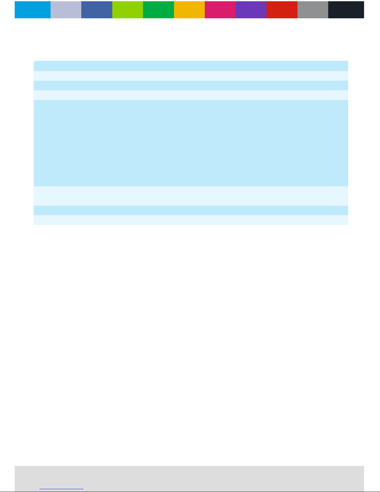
07 CHANNELS VALUE DESCRIPTION
1. Dimming 000 - 255 0 - 100%
2. Cool white 000 - 255 0 - 100%
3. Warm white 000 - 255 0 - 100%
4. CCT
000 - 010 No function
011 - 040 White 1: 2800K
041 - 070 White 2: 3000K
071 - 100 White 3: 3200K
101 - 130 White 4: 3400K
131 - 160 White 5: 4200K
161 - 190 White 6: 4900K
191 - 220 White 7: 5600K
221 - 255 White 8: 5900K
5. Strobe
000 - 001 No function
002 - 255 0 - 20Hz
6. Dimmer speed 000 - 255 Dimmer speed
7. ID 000 - 255 ID address selection
Page 14
WWW.CLF-LIGHTING.COM
Physical
Length 255mm
Width 205mm
Height 300mm
Weight 4 kg
Dynamic Eects
LED color mixing Cold white / warm white
LED color temperature control Variable 2800K (91 CRI) - 6500K (85 CRI)
Optics
Light source 36 high power LED’s, 18x CW & 18x WW
Control and Programming
Control DMX / master / slave
DMX channels 2 / 3 / 7
Setting and addressing Control panel with seven digit display
Protocol DMX512-A
Control and Programming
Color Black
Housing High strength die-casting aluminum
Protection rating IP 22
Installation
Orientation Any
Minimum distance to combustible materials 100 mm. from xture
Minimum distance to illuminated surfaces 200 mm. from xture
Connections
AC power input PowerCON input socket
AC power output PowerCON output socket
DMX data in/out 3-pin locking XLR
Electrical
AC power 100-240 V nominal, 50/60 Hz
Maximum total power consumption 90 W
Power supply unit Auto-ranging electronic switch mode
Power consumption in standby mode 2 W
Power consumption
120 V, 60 Hz 90 W, PF 0.6
240 V, 50 Hz 90 W, PF 0.6
PF = power factor. Measurements made at nominal voltage with all LEDs at full intensity. Allow for a deviation of +/- 10%. Thermal
Cooling Convection
Maximum ambient temperature (Ta max.) 40° C
Minimum ambient temperature (Ta min.) 5° C
Specications
12.0
Page 15
WWW.CLF-LIGHTING.COM
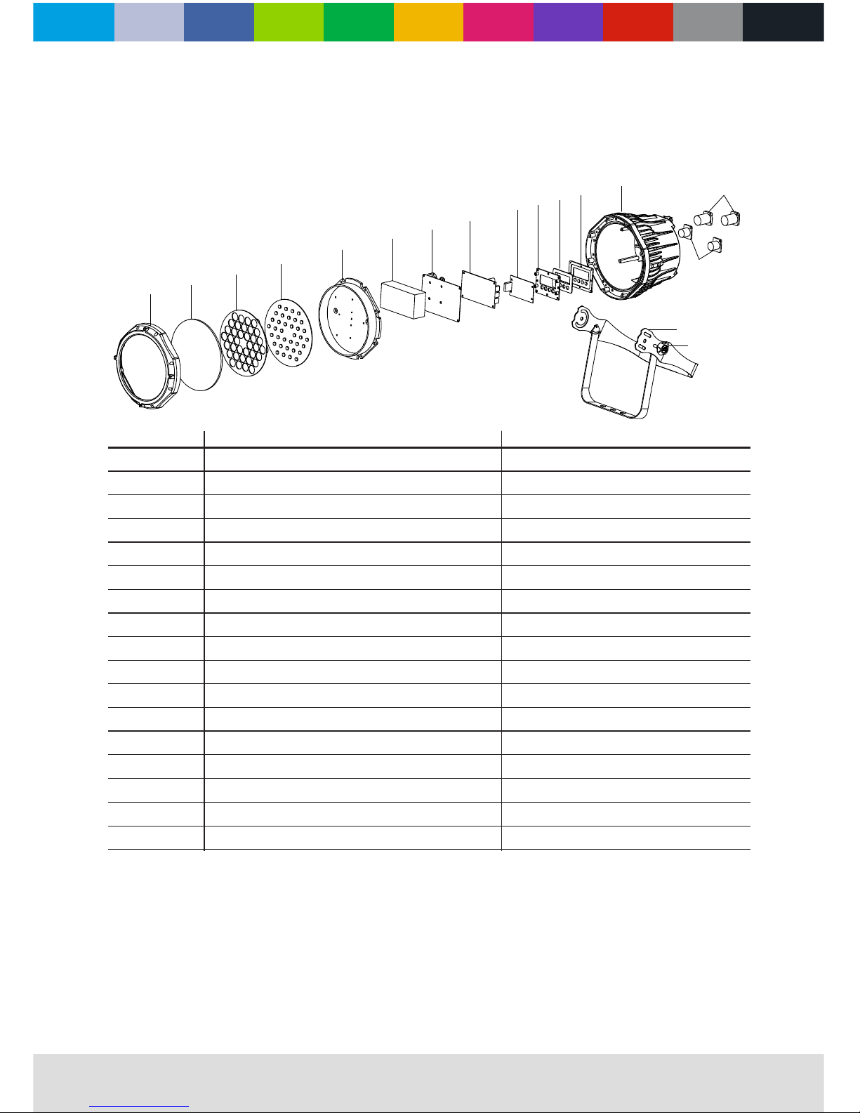
blow out diagram
Blow-out Diagram.
1
2
3
4
5
6
7
8
9
10
11
12
13
14
15
16
17
1
2
3
4
5
6
7
8
9
10
11
12
13
14
15
16
17
Description
Front cover ring
Tempered front glass
Lens holder
LED Board
LED Board radiator
Power supply
Power supply support bracket
LED Driver board
Display board
Display board support bracket
Display screen cover
Rubber button pad
Dynamic white case body
Power socket set
DMX socket set
Bracket complete
Knob bracket
Part Number
CLF-02-019
CLF-02-021
CLF-02-022
CLF-02-039
CLF-02-037
CLF-02-024
CLF-02-038
CLF-02-025
CLF-02-026
CLF-02-027
CLF-02-028
CLF-02-029
CLF-02-030
CLF-02-031
CLF-02-032
CLF-02-033
CLF-02-034
13.0
Page 16

WWW.CLF-LIGHTING.COMCLFLIGHTING
DYNAMIC WHITE PAR
 Loading...