

Page 1
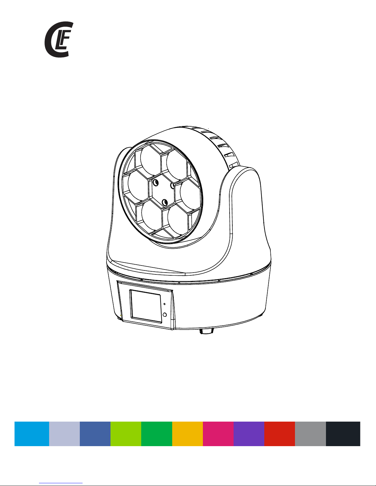
manual
V1.0 NOVEMBER 2017WWW.CLF-LIGHTING.COM
beam 6
Page 2
WWW.CLF-LIGHTING.COM
2
Safety instructions 3
Fixture overview 4
Dimensions 4
Photometric data 5
Physical installation 5
Mounting 6
Power and signal connection 7
Power connection 8
Control mode 9
Circuit connecting diagrtam 9
Onboard control menu 10
DMX protocol 14
Cleaning and maintenance 16
Specications 16
table of CONTENTS
Page 3

WWW.CLF-LIGHTING.COM
3
Safety instructions
Safety instructions
The following symbols ar e us ed t o id en ti fy i mp or ta nt s af et y in fo rm at io n on t he p ro du ct and in this manual:
WARNING!
Read the safety precautions in this section before
installing, powering, operating or servicing this
product
DANGE R!
Safet y hazar d.
Risk of s evere
injur y or deat h.
DANGE R!
Hazar dous
volta ge. Ris k of
letha l or seve re
elect ric sho ck.
WAR NING!
Fire ha zard.
WAR NING!
LED lig ht
emiss ion. Ri sk of
eye inj ury.
WAR NING!
Burn ha zard. H ot
surfa ce. Do no t
touch .
WAR NING!
Wea r pr ote ctive
eyewe ar.
WAR NING!
Refer t o user
m
anual .
WARNING!
Read the safety precautions in this section before
installing, powering, operating or servicing this
product
WARNING!
To guarantee proper and consistent operation, it is important to follow the
guidelines in this manual. The manufacturer will not accept responsibility for
damages resulting from the misuse of this xture due to the disregard of the information printed in this manual.
In order to ensure the xture could operate normally, the ambient temperature must not exceed 38°C and 0°C. Under
normal conditions, the highest sectional surface temperature will be up to 60°C.
The xture is designed with electric shock protection. The xture should be connected to a power supply system with
earth grounding. The xture’s ground cable should be connected with the ground cable of the power supply system as
well.
When the isolation is damaged please ask the manufacturer, distributor or a professional mechanic for a new power
cable as replacement in order to avoid dangerous situations.
Never open the xture while power is connected.
Never look directly into the light source. You risk injury to your eyes, which may cause blindness.
Please be aware that damages caused by modications to the device are not subject to warranty.
Page 4

WWW.CLF-LIGHTING.COM
4
xture overview
operation panel
dimensions
operation panel
dimensional drawings
155
268
226
Page 5
WWW.CLF-LIGHTING.COM
5
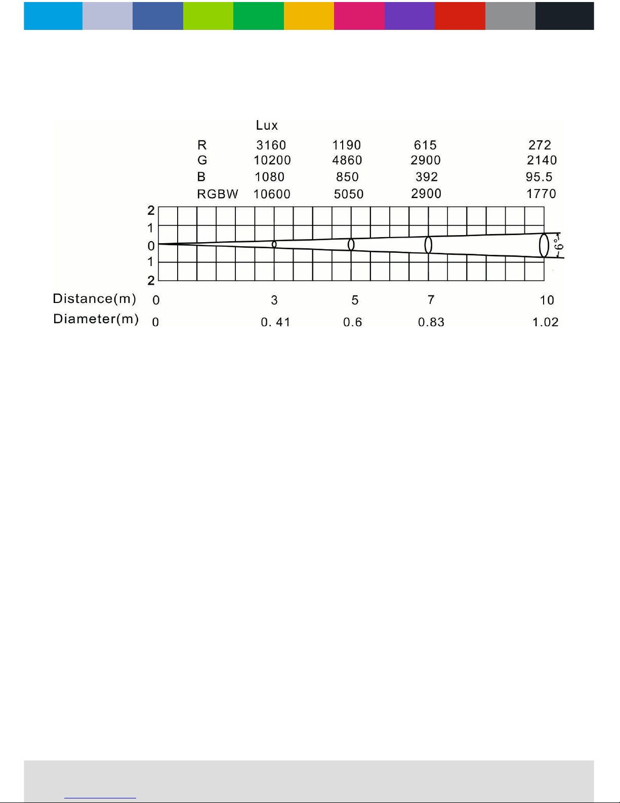
photometric data
photometric data
physical installation
CAUTION:
Before mounting the xture to any surface, make sure that the installation area can hold a minimum point load of 10 times the device’s
weight. Fixture installation must always be secured with a secondary safety attachment, such as an appropriate safety cable.
To avoid injury, never stand directly below the device when mounting, removing, or servicing the xture.
MOUNTING POINTS:
Overhead mounting requires experience, including calculating working load limits, knowledge of the installation material being used and
periodic safety inspection of all installation materials and the xture. If you don’t have these qualications, do not attempt the installation
yourself. Wrong installation can result in injuries. Be sure to complete all rigging and installation procedures before connecting the main
power cord to the appropriate wall outlet.
Page 6

WWW.CLF-LIGHTING.COM
6
MOUNTING:
The xture is operational in any mounting position. Be sure the xture is kept at least 50cm away from any ammable materials (decoration
etc.).
When mounted with a clamp, always use and install the supplied safety cable as a safety measure to prevent accidents.
Quicklock
Page 7
WWW.CLF-LIGHTING.COM
7
power and signal connection
POWER SUPPLY:
Use powerCON plug to connect the xture to the main power supply.
Please check if the voltage and the frequency are the same as mentioned on the xture.
SIGNAL CONNECTION:
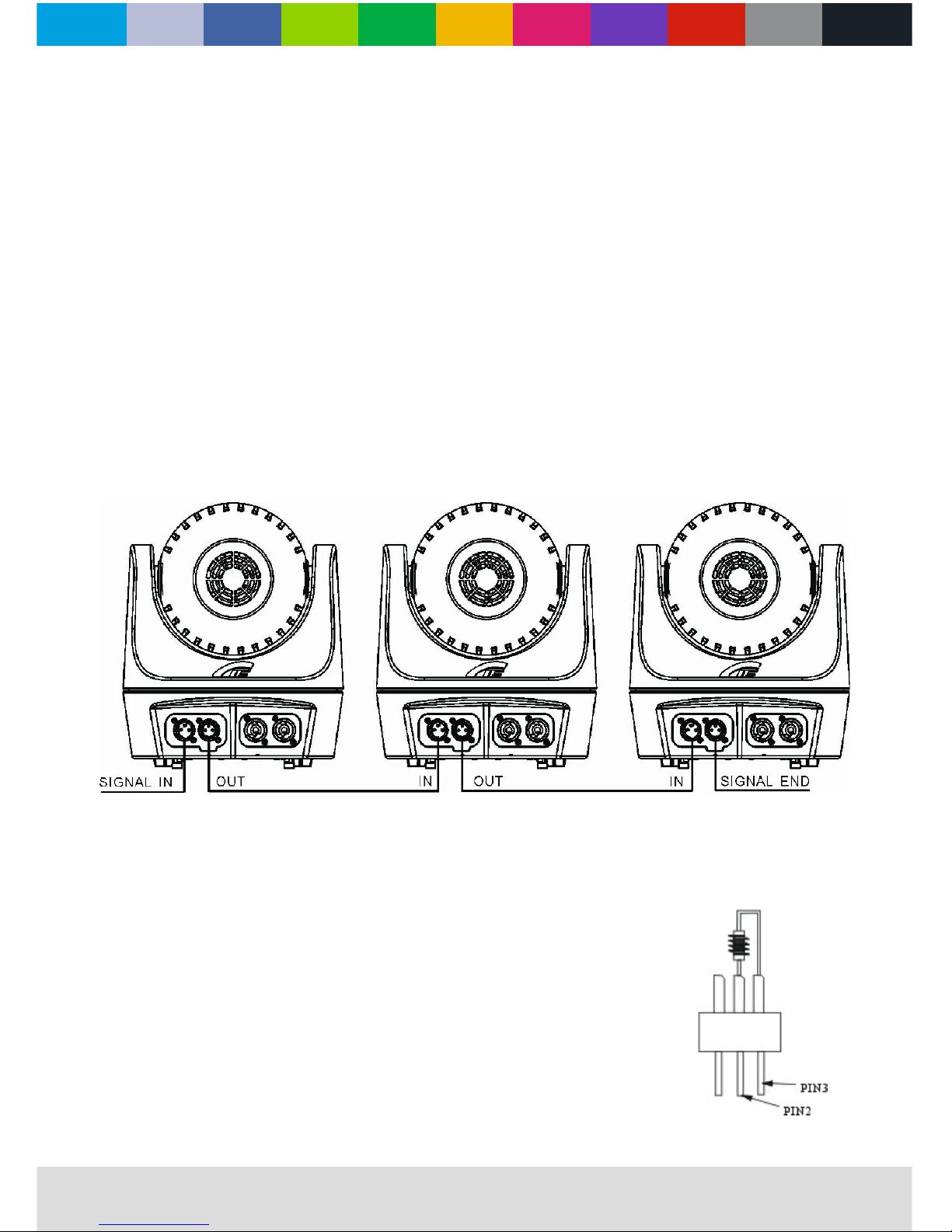
Please use the 5 pin XLR connectors to connect the rst xture’s DMX output to the next xture’s input, and so on.
As connect in the following gure.
power and signal connection
POWER SUPPLY:
Use the professional plug to connect the projector to the main power supply. Please check
if the voltage and the frequency are the same as mentioned on the projector. When each
SIGNAL CONNECTION:
s output to the
s input. And
in the same way for the rest, eventually connect the last device’s output, all the devices are
The device control signal output and input uses the 5-pin XLR plug and socket.
The resistance of each core is at least a diameter of 0.5mm. (Notice: The inside leading wire
of the 5-pin XLR plug can’t touch each other or the earth). We recommend to use the DMX
signal terminator during the installation to avoid electronic reection of the digital control
signal. The DMX terminator is a XLR connector with a 120Ω & 1/2W resistor connected across
pin 2 and 3 (see picture on the right). Which is plugged into the output socket on the last
xture in the chain. Refer to the connection as in above picture. We advise to use a DMX
signal distributor when the distance of the lights is more then 15 meter, to prevent signal loss.
s output to the
s input. And
Page 8
WWW.CLF-LIGHTING.COM
8
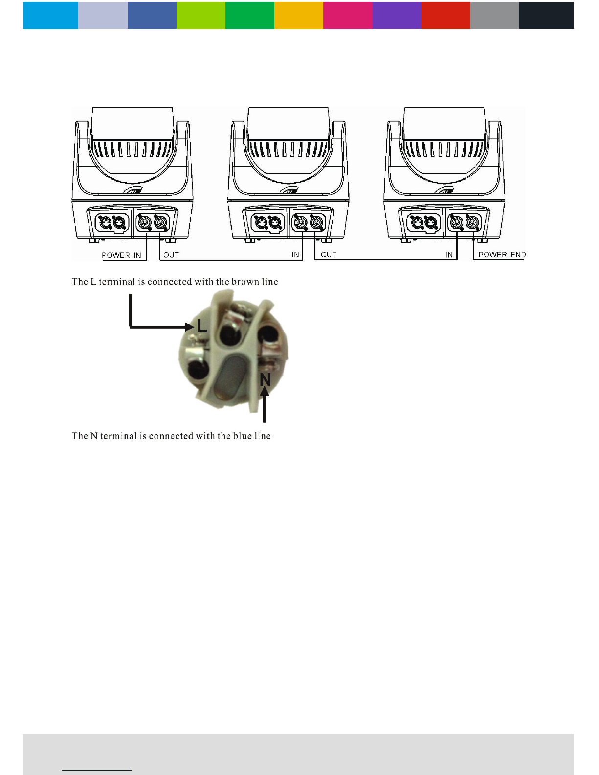
power connection
light power connection
Do not daisychain more then 6 xtures.
Page 9
WWW.CLF-LIGHTING.COM
9
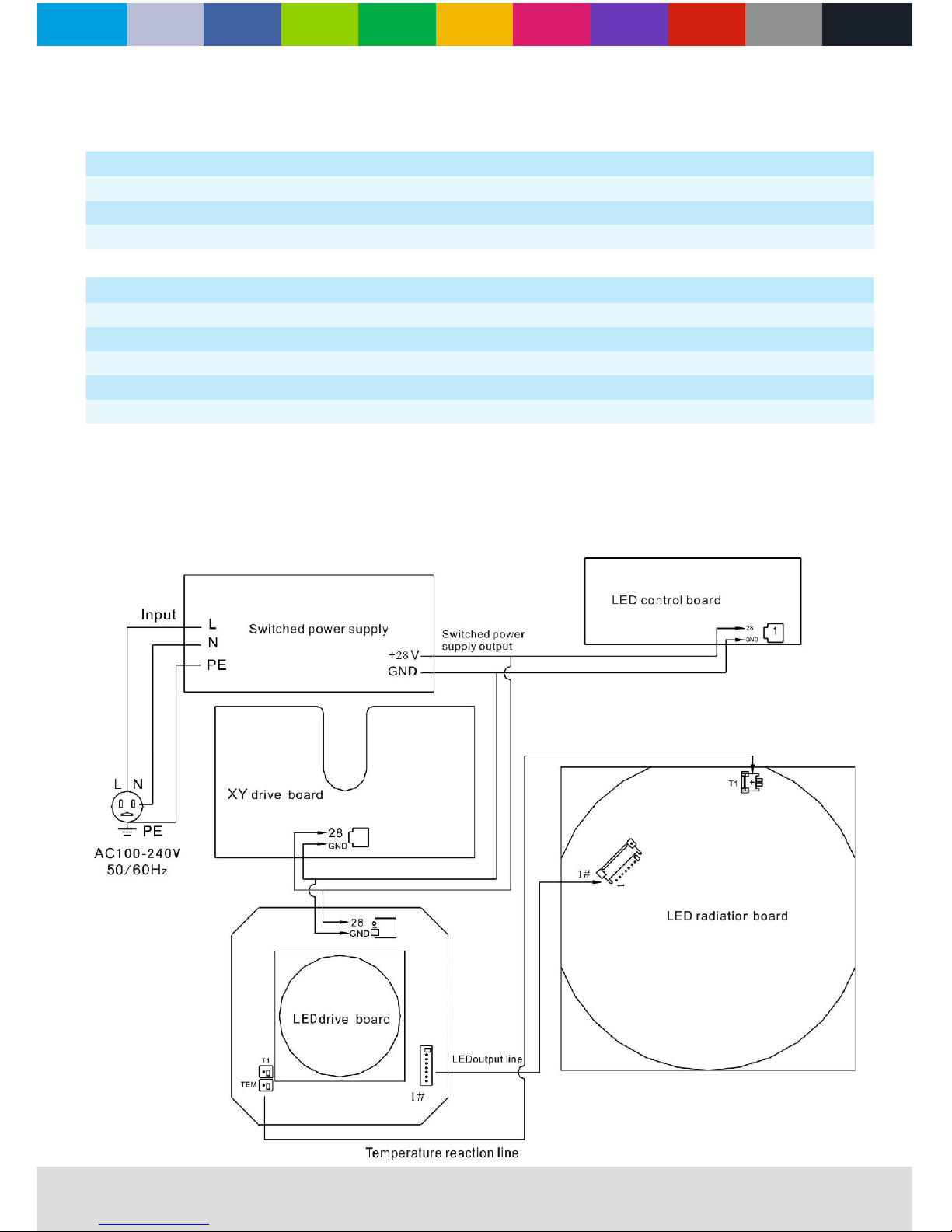
circuit connection diagram
STANDARD 11CH
1. Dimmer 4. Green 7. Pan 10. Rota speed
2. Shutter 5. Blue 8. Tilt 11. Fixture control
3. Red 6. White 9. Rota lens
channels
STANDARD 17CH
1. Dimmer 6. Blue 11. Tilt 16. Calibration
7. White 17. Slave ID
3. Shutter 8. Macro color 13. Rota lens
4. Red 9. Pan 14. Rota speed
5. Green
15. Fixture control
circuit connection diagram
STANDARD 11CH
1. Dimmer 4. Green 7. Pan 10. Rota speed
2. Shutter 5. Blue 8. Tilt 11. Fixture control
3. Red 6. White 9. Rota lens
control mode
STANDARD 17CH
1. Dimmer 6. Blue 11. Tilt 16. Calibration
2. Dimmer ne 7. White 12. Tilt ne 17. Slave ID
3. Shutter 8. Macro color 13. Rota lens
4. Red 9. Pan 14. Rota speed
5. Green 10. Pan ne 15. Fixture control
Page 10
WWW.CLF-LIGHTING.COM
10
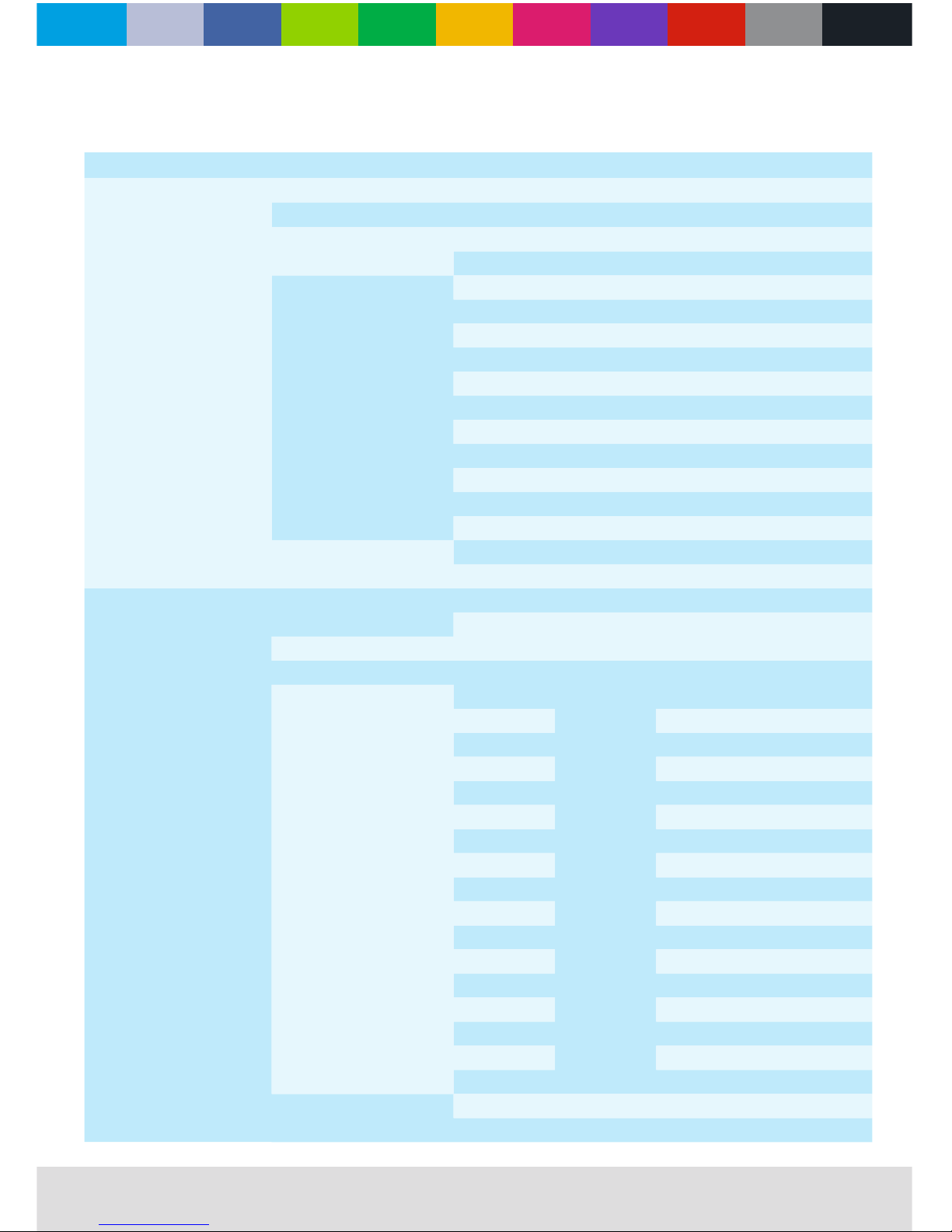
onboard control menu
MENU REMARK
Setting
DMX address 001 - 512
Fixture ID
000 - 064
Channel mode
Standard 11CH Default
Extended 17CH
DMX Function
Hold
Black
D. scene
Program 1
Program 2
Program 3
Program 4
Program 5
Program 6
Program 7
Program 8
Slave - Master
Slave mode
Master mode
Info
Fixture times
Power on time ****H
Lamp on time ****H
Fixture temperature Lamp_tem ****°C
RDM UID ********
DMX live
1. Dimmer
0 - 255
2. Dimmer ne
3. Shutter
4. Red
5. Green
6. Blue
7. White
8. Macro color
9. Pan
10. Pan ne
11. Tilt
12. Tilt ne
13. Rota lens
14. Rota sp
15. Fixturecontrol
16. Calibration
17. Slave ID
Version info
LED_XY_SOFT:V2.00
LED_DPY_SOFT:V4.00
Page 11
WWW.CLF-LIGHTING.COM
11
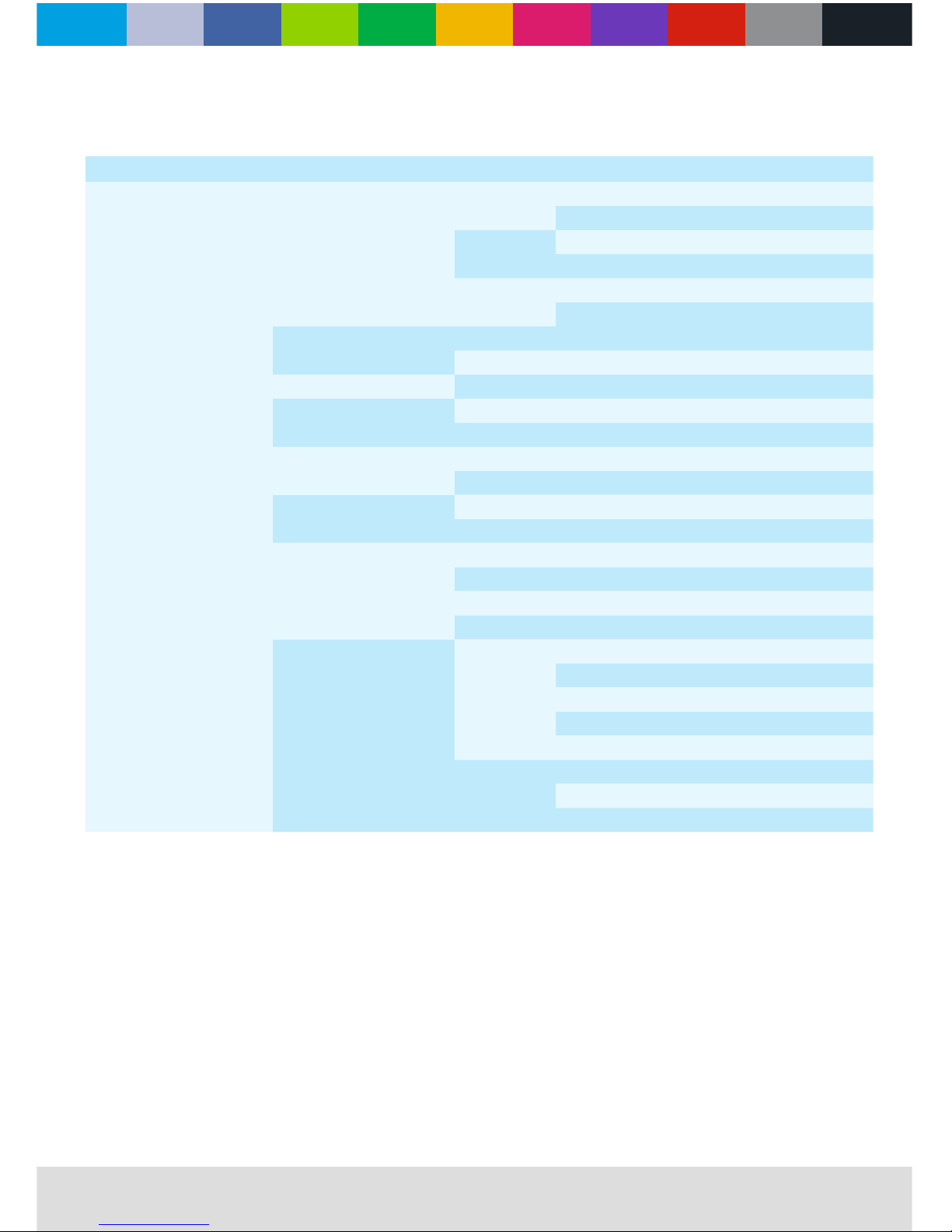
onboard control menu
MENU REMARK
Personality
Pan / Tilt
P/T swap
OFF Default
ON
Pan invert
OFF Default
ON
Tilt invert
OFF Default
ON
DMX reset
ON Default
OFF
Reset System reset
Quick closedown
ON Default
OFF
P/T angle limit
Close
Open
Program on/o
Close
Open
Set P/T angle
Pan start
Pan end
Tilt start
Tilt end
Display
Display sleep Light always
2 minutes
4 minutes
6 minutes
Display intensity 10 - 100
Display rotation Rotate 180
Normal
TFT calibration
Page 12
WWW.CLF-LIGHTING.COM
12
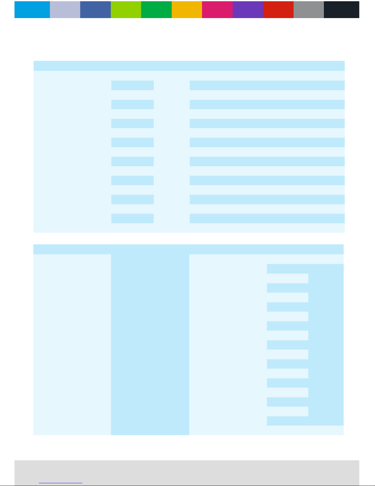
onboard control menu
MENU MENU I REMARK
Manual control
1. Dimmer
0 - 255
2. Dimmer ne
3. Shutter
4. Red
5. Green
6. Blue
7. White
8. Macro color
9. Pan
10. Pan ne
11. Tile
12. Tilt ne
13. Rota lens
14. Rota sp
15. Fixturecontrol
16. Calibration
17. Slave ID
MENU MENU IV
Program Edit program Edit program 1
Scene 0 - 100
1. Dimmer
0 - 255
2. Dimmer ne
3. Shutter
4. Red
5. Green
6. Blue
7. White
8. Macro color
9. Pan
10. Pan ne
11. Tilt
12. Tilt ne
13. Rota lens
14. Rota sp
15. Fixturecontrol
16. Calibration
17. Slave ID
Save scene
Page 13
WWW.CLF-LIGHTING.COM
13
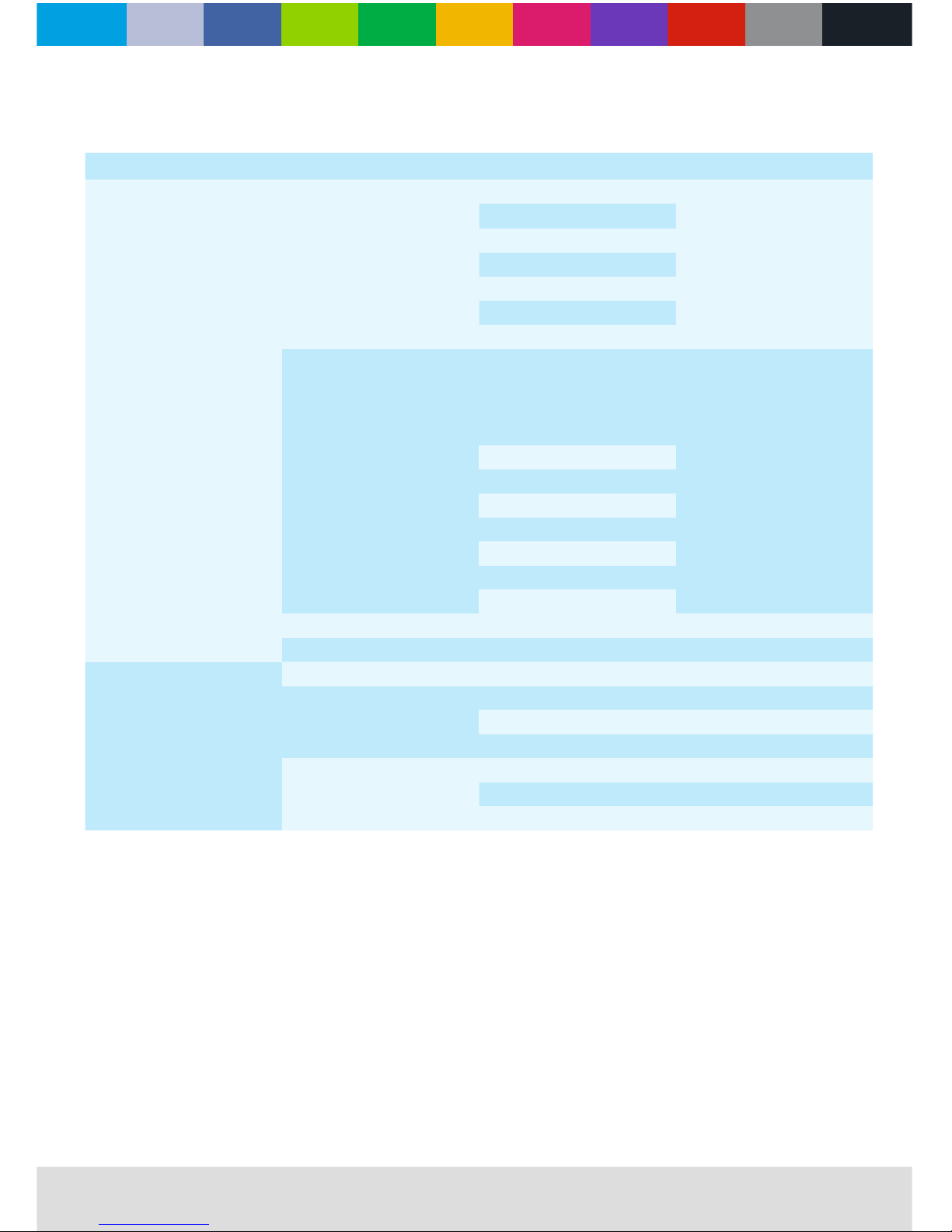
onboard control menu
MENU MENU IV
Program
Edit program
Edit program 2
Same as ‘Edit program 1‘
Edit program 3
Edit program 4
Edit program 5
Edit program 6
Edit program 7
Edit program 8
Set program
Set program 1
Start step 0 - 100
End step 0 - 100
Step time 0 - 255
Save
Set program 2
Same as ‘Set program 1‘
Set program 3
Set program 4
Set program 5
Set program 6
Set program 7
Set program 8
Run Running program
Fixed scene Scene 001 - 100
Service
Error list
Adjust
Pan ±5.00%
Tilt ±5.00%
Rotatable lens ±5.00%
Factory
Default
Adjust default
Firmware update ****
Page 14
WWW.CLF-LIGHTING.COM
14
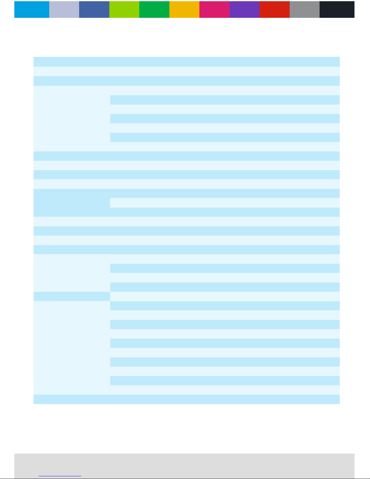
dmx protocol
CHANNEL DMX VALUES % EFFECT
1. Dimmer 0 - 255 0 - 100
2. Dimmer ne 0 - 255 0 - 100
3. Shutter
0 - 9 0 - 3
10 - 49 4 - 19 Light --> dark, slow --> fast
50 - 89 20 - 34 Dark --> light, slow --> fast
90 - 119 35 - 46 Dark --> light --> dark, slow --> fast
120 - 179 47 - 70 Random fast --> slow strobe
180 - 250 71 - 98 In-phase, slow --> fast
251 - 255 99 - 100 Unused range
4. Red 0 - 255 0 - 100
5. Green 0 - 255 0 - 100
6. Blue 0 - 255 0 - 100
7. White 0 - 255 0 - 100
8. Macro color
0 - 1 0 - 1
2 - 254 1 - 99 Shadow
255 100
9. Pan 0 - 255 0 - 100
10. Pan ne 0 - 255 0 - 100
11. Tilt 0 - 255 0 - 100
12. Tilt ne 0 - 255 0 - 100
13. Rotatable lens
0 - 127 0 - 49
128 - 135 50 - 52
136 - 231 53 - 90
232 - 255 91 - 100
14. Rota sp 0 - 255 0 - 100
15. Fixture control
0 - 9 0 - 3
10 - 14 4 - 5
15 - 19 6 - 7
20 - 24 8 - 9
25 - 29 10 - 11
30 - 34 12 - 13
35 - 239 14 - 93
240 - 244 94 - 95
245 - 249 96 - 97
250 - 255 98 - 100
16. Calibration 0 - 255 0 - 100
Page 15
WWW.CLF-LIGHTING.COM
15
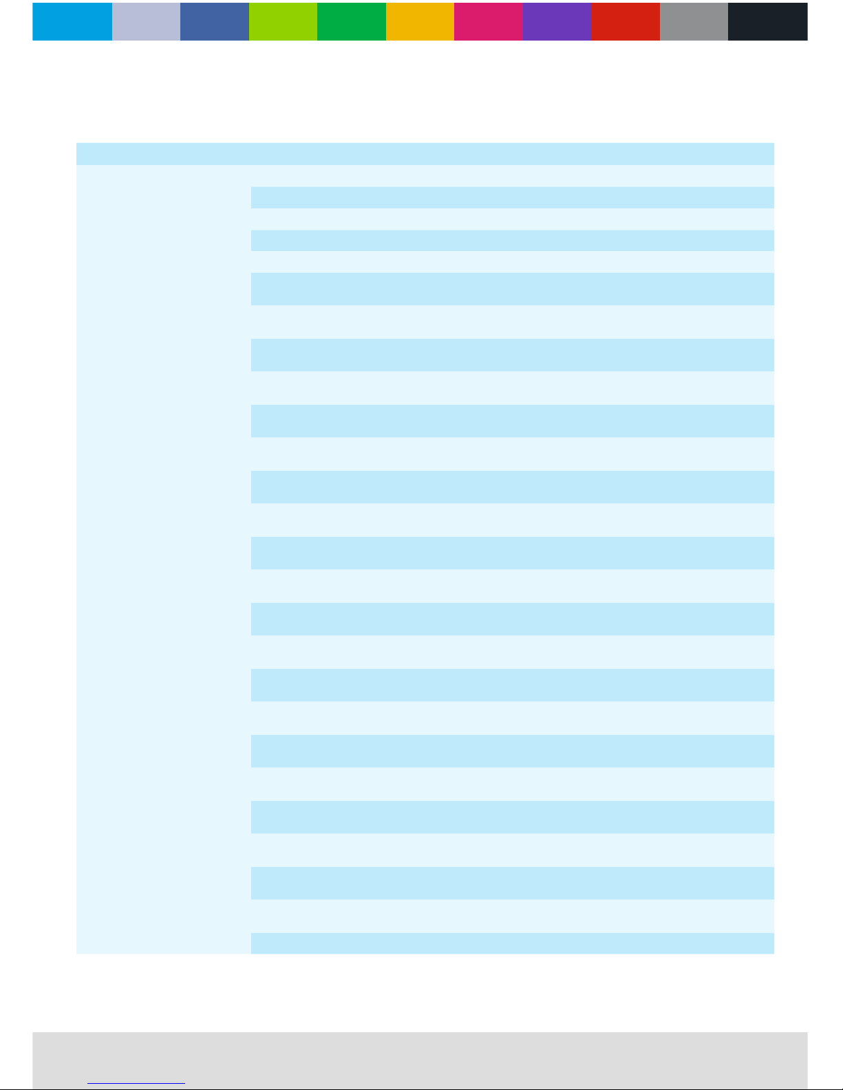
CHANNEL DMX VALUES % EFFECT
17. Slave ID
0 - 2 0
3 - 5 1 - 2 ID:1 eective
6 - 8 2 - 3 ID:2 eective
--- ---
192 - 194 75 - 76 ID:64 eective
195 - 197 76 - 77
ID is (2xn) + 1 eective, (n=0 - 31)
1, 3, 5, 7, 9 ... 63
198 - 200 77 - 78
ID is (2xn) + 2 eective, (n=0 - 31)
2, 4, 6, 8, 10 ... 64
201 - 203 78 - 79
ID is (3xn) + 1 eective, (n=0 - 21)
1, 4, 7, 10, 13 ... 64
204 - 206
80 - 81 ID is (3xn) + 2 eective, (n=0 - 20)
2, 5, 8, 11, 14 ... 62
207 - 209
81 - 82 ID is (3xn) + 3 eective, (n=0 - 20)
3, 6, 9, 12, 15 ... 63
210 - 212
82 - 83 ID is (4*n) + 1 eective, (n=0 - 15)
1, 5, 9, 13, 17 … 61
213 - 215
83 - 84 ID is (4*n) + 2 eective, (n=0 - 15)
2, 6, 10, 14, 18 … 62
216 - 218
84 - 85 ID is (4*n) + 3 eective, (n=0 - 15)
3, 7, 11, 15, 19 … 63
219 - 221 85 - 86
ID is (4*n) + 4 eective, (n=0 - 15)
4, 8, 12, 16, 20 … 64
222 - 224 87 - 88
ID is (5*n) + 1 eective, (n=0 - 12)
1, 6, 11, 16, 21 … 61
225 - 227 88 - 89
ID is (5*n) + 2 eective, (n=0 - 12)
2, 7, 12, 17, 22 … 62
228 - 230 89 - 90
ID is (5*n) + 3 eective, (n=0 - 12)
3, 8, 13, 18, 23 … 63
231 - 233
90 - 91 ID is (5*n) + 4 eective, (n=0 - 12)
4, 9, 14, 19, 24 … 64
234 - 236
91 - 92 ID is (5*n) + 5 eective, (n=0 - 11)
5, 10, 15, 20, 25 … 60
237 - 239
93 - 94 ID is (6*n) + 1 eective, (n=0 - 10)
1, 7, 13, 19, 25 … 61
240 - 242
94 - 95 ID is (6*n) + 2 eective, (n=0 - 10)
2, 8, 14, 20, 26 … 62
243 - 245
95 - 96 ID is (6*n) + 3 eective, (n=0 - 10)
3, 9, 15, 21, 27 … 63
246 - 248
96 - 97 ID is (6*n) + 4 eective, (n=0 - 10)
4, 10, 16, 22, 28 … 64
249 - 251
97 - 98 ID is (6*n) + 5 eective, (n=0 - 9)
5, 11, 17, 23, 29 … 59
252 - 254
98 - 99 ID is (6*n) + 6 eective, (n=0 - 9)
6, 12, 18, 24, 30 … 60
255 100 All ID’s are valid
dmx protocols
Page 16
WWW.CLF-LIGHTING.COM
16
• In order to ensure the xture could work normally it should be kept clean always .The lens should also be regularly cleaned to
maintain an optimum light output. Do not use any type of chemicals on the lens. It will damage the lens.
• Please disconnect the power supply of the xture when you start maintenance.
CAUTION: Disconnect the xture from the main power before you start with the maintenance.
cleaning and maintenance
specications
Voltage 240VAC 50/60Hz
Power 91W
LED chips 6x RGBW 4 in 1 LED chip
Lens degree Standard 1.5°
Beam angle Minimum 6°, maximum 51°
Color RGBW
Strobe 1-30 times / second electronic strobe and
random strobe
Pan 540°
Tilt 180°
Control mode DMX512, RDM ready
Channel Standard CH11 & extended CH17
Display menu 2.4 inch TFT touch screen
Software Upgrade by XLR cable
Fixture size 226 x 226 x 286 mm
Netto weight 3,8 kg
Fixture size 226 x 268mm
Ambient temperature 0°C - 38°C
Page 17

WWW.CLF-LIGHTING.COMCLFLIGHTING
beam 6
 Loading...