


Contents
About this Concise User Guide .........................................................1
System Startup ..................................................................................4
System Map: Front View with LCD Panel Open (Models A & B) ..6
System Map: Front View with LCD Panel Open (Models C & D) ..7
LED Indicators ..................................................................................8
Keyboard ...........................................................................................9
Function Keys & Visual Indicators .................................................10
Control Center ......... .......................................................... ..............11
System Map: Front, Left, Right, Rear & Bottom Views ................13
(Models A & B) .......................................... ............................. .......13
System Map: Front, Left, Right, Rear & Bottom Views
(Models C & D) .......................................... ............................. .......14
Windows 8.1 Control Panel ............................................................15
Windows 8.1 Start Screen & Desktop ............................................15
Apps & Tiles ...................................................................................16
Charms Bar ............................. ........................................................16
Video Features ................................................................................17
Audio Features ................................................................................19
Power Options .................................... ............................. ................20
Driver Installation .................................................................. .........21
3G Module ......................................................................................22
Troubleshooting ..............................................................................23
Specifications ............... ................................. .................................. 24
Inhalt
Über das Ausführliche Benutzerhandbuch .....................................27
Schnellstart ................... ............... .................. .................. ................30
Systemübersicht: Ansicht von vorne mit geöffnetem LCD-Bildschirm
(Modelle A & B) .............. ........................................................ .......32
Systemübersicht: Ansicht von vorne mit geöffnetem LCD-Bildschirm
(Modelle C & D) .............................................................................33
LED-Anzeigen ............... ................................................... ..............34
Tastatur ................... ......................... ........................ ........................35
Funktionstasten ................................................................................36
Control Center (Steuerzentrum) .................................................... ..37
Systemübersicht: Ansicht von vorne, links, rechts, hinten und unten
(Modelle A & B) ....................................................................... ......39
Systemübersicht: Ansicht von vorne, links, rechts, hinten und unten
(Modelle C & D) ....................................................................... ......40
Windows 8.1 Systemsteuerung .......................................................41
Windows 8.1 Start-Bildschirm und Desktop ...................................41
Apps und Kacheln ...........................................................................42
Charms-Leiste .................................................................................42
Grafikfunktionen ................................................. ............................43
Audiofunktionen ..............................................................................45
Energieoptionen ..............................................................................46
Installation der Treiber ....................................................................47
3G-Modul ........................ ............................................. ...................48
Fehlerbehebung ...............................................................................49
Technische Daten ............................................................................50
Sommaire
A propos de ce Guide Utilisateur Concis ........................................53
Guide de démarrage rapide .............................................................56
Carte du système: Vue de face avec l’écran LCD ouvert
(Modèles A & B) ...................................................... ......................58
Carte du système: Vue de face avec l’écran LCD ouvert
(Modèles C & D) ... ............................. ............................. ...............59
Indicateurs LED ....................... ............................. ..........................60
Clavier ...................... .................................................... ...................61
Touches fonction .... ............................. ............................. ...............62
Control Center (Centre de contrôle) .......................... ......................63
Carte du système: Vues de face, gauche, droite, arrière & dessous
(Modèles A & B) ....................................................... ......................65
Carte du système: Vues de face, gauche, droite, arrière & dessous

(Modèles C & D) ...........................................................................66
Panneau de Configuration de Windows 8.1 ....................................67
Écran d'accueil & bureau de Windows 8.1 .....................................67
Applications et Vignettes ................................................................68
Barre des charmes ...........................................................................68
Caractéristiques vidéo .....................................................................69
Caractéristiques audio .....................................................................71
Options d’alimentation ....................................................................72
Installation du pilote .......................................................................73
Module 3G .................................. ....................................................74
Dépannage .................. ...... ....... .... ....... ..... ...... ..... ...... ....... .... ....... .....75
Spécifications ............... ................................. .................................. 76
Contenidos
Acerca de esta Guía del Usuario Concisa .......................................79
Guía rápida para empezar ...............................................................82
Diferencias de modelos ...................................................................83
Mapa del sistema: Vista frontal con panel LCD abierto
(Modelos A & B) ................................................................... .........84
Mapa del sistema: Vista frontal con panel LCD abierto
(Modelos C & D) ............................................................................85
Indicadores LED ...................................................................... .......86
Teclado ....................... ............. ................ ............... ................ .........87
Control Center (Centro de control) .... ............................... ..............89
Mapa del sistema: Vistas frontal, izquierda, derecha, posterior
e inferior (Modelos A & B) ............................................................91
Mapa del sistema: Vistas frontal, izquierda, derecha, posterior
e inferior (Modelos C & D) ............................................................92
Panel de Control de Windows 8.1 ...................................................93
Pantalla Inicio y escritorio de Windows 8.1 ...................................93
Apps y Mosaicos .............................................................................94
Barra Charms ................................... ............................. ..................94
Parámetros de vídeo .............. ..........................................................95
Características de audio ...................................................................97
Opciones de energía ........................................................................98
Instalación de controladores ............................................................99
Módulo 3G ....................................................................................100
Solución de problemas ................................. ............................. ....101
Especificaciones ................ ............................................... .............102
Sommario
Informazioni su questa guida rapida .............................................105
Guida di avvio rapido ....................................................................108
Descrizione del sistema: Vista anteriore con pannello LCD aperto
(Modelli A & B) ...........................................................................110
Descrizione del sistema: Vista anteriore con pannello LCD aperto
(Modelli C & D) ................................................... ........................111
Indicatori LED ............. ..................................................................112
Tastiera ................... ............................................. ..........................113
Tasti funzione ................................................................................114
Control Center (Centro di controllo) .............................................115
Descrizione del sistema: Vista anteriore, sinistra, destra, posteriore e
inferiore (Modelli A & B) .................................................. .. .........117
Descrizione del sistema: Vista anteriore, sinistra, destra, posteriore e
inferiore (Modelli C & D) .................................................. .. .........118
Pannello di controllo di Windows 8.1 ...........................................119
Schermata Start e Desktop di Windows 8.1 ... ...............................119
App & Titoli ..................................................................................120
Charms Bar ....................................................................................120
Funzioni video . ............................. ............................. ... .................121
Funzionalità audio .........................................................................123
Opzioni risparmio energia ........ ............................. .. ......................124
Installazione driver ...... ....................................................... ...........125
Modulo 3G ....................................................................................126
Risoluzione dei problemi ..............................127
Specifiche tecniche ...................................128

About this Concise User Guide
FCC Statement
This device complies with Part
15 of the FCC Rules. Operation
is subject to the following two
conditions:
1.This device may not cause
harmful interference.
2. This device must accept any
interference received, including interference that may
cause undesired operation.
This quick guide is a brief introduction to getting your system started. This is a s upplement, and not a substitute for the
expanded English language User’s Manual in Adobe Acrobat format on the Device Drivers & Utilities + User’s Manual
disc supplied with your computer. This disc also contains the drivers and utilities necessary for the proper oper ation of
the computer (Note: The company reserves the right to revise this publication or to change its contents without notice).
Some or all of the computer’s features may already have been setup. If they aren’t, or you are planning to re-configure
(or re-install) portions of the system, refer to the expanded User’s Manual. The Device Drivers & Utilities + User’s
Manual disc does not contain an operating system.
Regulatory and Safety Information
Please pay careful attention to the full regulatory notices and safety information contained in the expanded User’s Manual on the Device Drivers & Utilities + User’s Manual disc.
© January 2014
Trademarks
Intel, Intel Core and Pentium are trademarks/registered trademarks of Intel Corporation.
English
1

Instructions for Care and Operation
The computer is quite rugged, but it can be damaged. To prevent this, follow these suggestions:
• Don’t drop it, or expose it to shock. If the computer falls, the
case and the components could be damaged.
• Keep it dry, and don’t overheat it. Keep the computer and
power supply away from any kind of heating element. This is an
electrical appliance. If water or any other liquid gets into it, the
English
computer could be badly damaged.
• Avoid interfer ence. Keep the computer away from high capacity
transformers, electric motors, and other strong magnetic fields.
These can hinder proper performance and damage your data.
• Follow the proper working procedures for the computer. Shut
the computer down properly and don’t forget to save your work.
Remember to periodically save your data as data may be lost.
Servicing
Do not attempt to service the computer yourself. Doing so may
violate your warranty and expose you and the computer to
electric shock. Refer all servicing to authorized service personnel. Unplug the computer from the power supply. Then refer
servicing to qualified service personnel under any of the fo llowing conditions:
• When the power cord or AC/DC adapter is damaged or frayed.
• If the computer has been exposed to any liquids.
• If the computer does not work normally when you follow the
operating instructions.
• If the computer has been dropped or damaged (do not touch the
poisonous liquid if the LCD panel breaks).
• If there is an unusual odor, heat or smoke coming from your computer.
Safety Information
• Only use an AC/DC adapter approved for use with this computer.
• Use only the power cord and batteries indicated in this manual.
Do not dispose of batteries in a fire. They may explode. Check
with local codes for possible special disposal instructions.
• Do not continue to use a battery that has been dropped, or that
appears damaged (e.g. bent or twisted) in any way. Even if the
computer continues to work with a damaged battery in place, it
may cause circuit damage, which may possibly result in fire.
• Make sure that your computer is completely powered off before
putting it into a travel bag (or any such container).
• Before cleaning the computer, make sure it is disconnected from
any external power supplies, peripherals and cables (including
telephone lines). It is advisable to also remove your battery in
order to prevent accidentally turning the machine on.
• Use a soft clean cloth to clean the computer, but do not apply
cleaner directly to the computer. Do not use volatile (petroleum
distillates) or abrasive cleaners on any part of the computer.
• Do not try to repair a battery pack. Refer any battery pack repair
or replacement to your service representative or qualified service
personnel.
• Note that in computer’s featuring a raised LCD electro-plated
logo, the logo is covered by a protective adhesive. Due to general
wear and tear, this adhesive may deteriorate over time and the
exposed logo may develop sharp edges. Be careful when handling
the computer in this case, and avoid touching the raised LCD
electro-plated logo. Avoid placing any other items in the carrying
bag which may rub against the top of the computer during transport. If any such wear and tear develops contact your service center.
2

Polymer Battery Precautions
Battery Disposal & Caution
The product that you have purchased contains a rechargeable battery. The battery is recyclable. At the end of its useful life, under various state and local laws, it may be illegal
to dispose of this battery into the municipal waste stream.
Check with your local solid waste officials for details in your
area for recycling options or proper disposal.
Danger of explosion if battery is incorrectly replaced. Replace only with the same or equivalent type recommended
by the manufacturer. Discard used battery a ccording to the
manufacturer’s instructions.
Note the following information which is specific to polymer
batteries only, and where applicable, this overrides the general
battery precaution information.
• Polymer batteries may experience a slight expansion or swelling,
however this is part of the battery’s safety mechanism and is not a
cause for concern.
• Use proper handling procedures when using polymer batteries.
Do not use polymer batteries in high ambient temperature environments, and do not store unused batteries for extended periods.
English
3
System Startup
Shut Down
Note that you should always shut your
computer down by choosing the Shut
down command in Windows (see below).
This will help prevent hard disk or system
problems.
Click Settings in the Charms Bar (use the
Windows Logo Key + C key combi-
nation to access the Charms Bar) and
choose Shut down from the Power menu.
Or
Choose Shut down or sign out > Shut
down from the context menu (use the Windows Logo Key + X key combination
to access the context menu).
130°
Figure 1
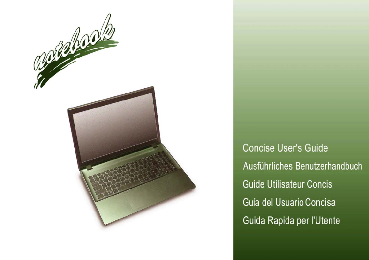
Opening the Lid/LCD/Computer with AC/DC Adapter Plugged-In
1. Remove all packing materials.
2. Place the computer on a stable surface.
3. Insert the battery and make sure it is locked in
position.
4. Securely attach any peripherals you want to use
with the computer (e.g. keyboard and mouse) to
their ports.
5. Attach the AC/DC adapter to the DC-In jack on
English
the left of the computer, then plug the AC power
cord into an outlet, and connect the AC power
cord to the AC/DC adapter.
6. Use one hand to raise the
comfortable viewing angle
;
degrees)
Figure 1) to support the base of the computer
(Note: Never lift the computer by the lid/LCD).
7. Press the power button to turn the computer
“on”.
System Software
Your computer may already come with system software pre-installed. Where this is not
the case, or where you are re-configuring
your computer for a different system, you will
find this manual refers to Microsoft Windows
8.1.
use the other hand (as illustrated in
lid/LCD to a
(do not exceed 130
4
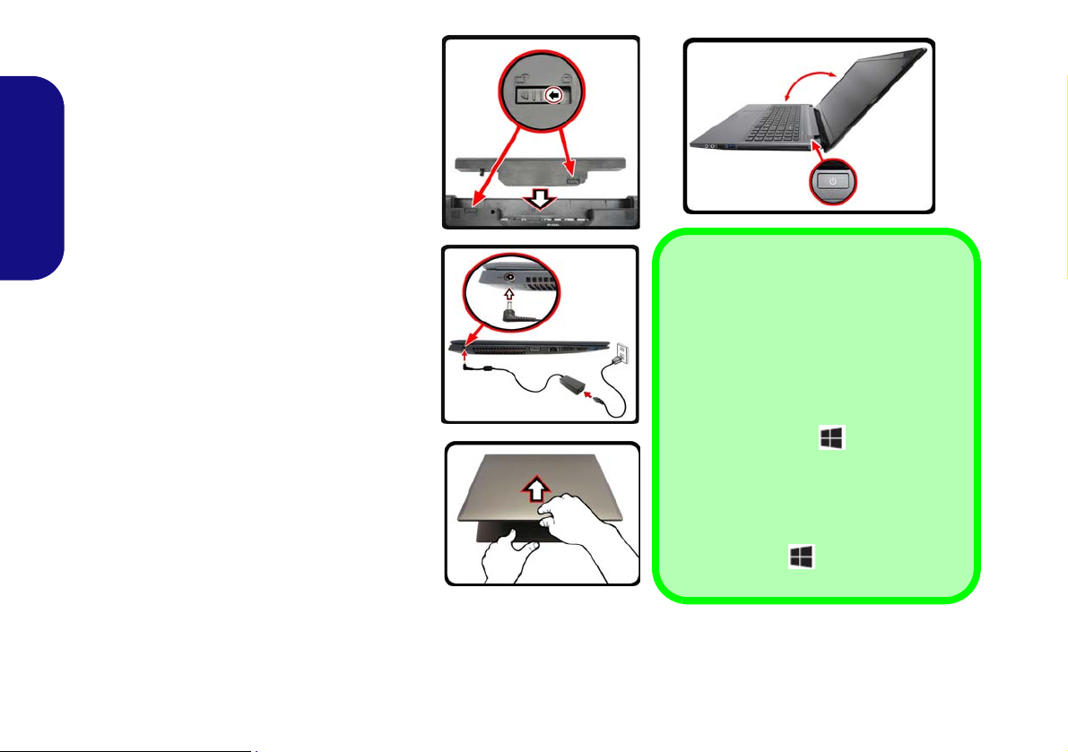
Model Differences
This notebook series includes four different model types that mainly differ as indicated in the table below. Note that
your model may appear slightly different from those pictured in this manual.
Feature Model A Model B Model C Model D
English
Video Adapter
Display
3G Module
Power Supply
Intel® Integrated GPU
(Intel® HD Graphics 4600/
Intel® HD Graphic) and
NVIDIA® Discrete GPU
(NVIDIA®
DC Output 19V, 4.74A
GeForce
(90W)
840M
15.6" (39.62cm) HD/FHD 17.3" (43.94cm) HD+/FHD
Intel® Integrated GPU
(Intel® HD Graphics 4600/
Intel® HD Graphic) and
NVIDIA® Discrete GPU
(NVIDIA®
)
Option No
DC Output 19.5V, 6.15A
GeForce GTX
850M
)
(120W)
Intel® Integrated GPU
(Intel® HD Graphics 4600/
Intel® HD Graphic) and
NVIDIA® Discrete GPU
(NVIDIA®
DC Output 19V, 4.74A
GeForce
(90W)
840M
)
Table 1 - Model Differences
Intel® Integrated GPU
(Intel® HD Graphics 4600/
Intel® HD Graphic) and
NVIDIA® Discrete GPU
(NVIDIA®
DC Output 19.5V, 6.15A
GeForce GTX
850M
)
(120W)
5
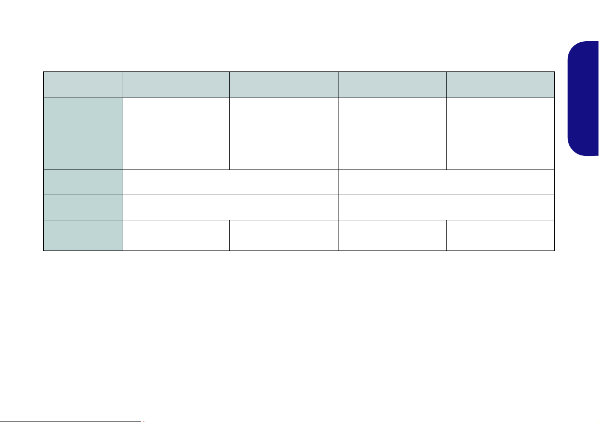
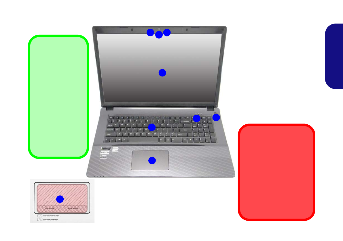
System Map: Front View with LCD Panel Open (Models A & B)
Note that the Touchpad and
Buttons valid operational area
is that indicated within the red
dotted lines.
Figure 2
Front View with LCD Panel Open
(Models A & B)
1. PC Camera
2. Built-In Microphone
3. *PC Camera LED
*When the PC camera is in use,
the LED will be illuminated in red.
4. LCD
5. Power Button
6. LED Indicators
7. Keyboard
8. Touchpad & Buttons
5
7
6
2
1
3
4
Wireless Device
Operation Aboard Aircraft
The use of any portable electronic
transmission devices aboard aircraft
is usually prohibited.
Make sure the WLAN & Bluetooth
module(s) are OFF if you are using
the computer aboard aircraft by putting the system in to Airplane Mode.
8
8
English
6
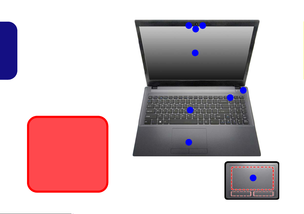
System Map: Front View with LCD Panel Open (Models C & D)
Figure 3
Front View with LCD Panel
Open (Models C & D)
1. PC Camera
2. Built-In Microphone
3. *PC Camera LED
*When the PC camera is in
use, the LED will be
illuminated in red.
4. LCD
5. Power Button
6. LED Indicators
7. Keyboard
8. Clickpad/Touchpad
5
7
6
2
1
3
4
Wireless Device
Operation Aboard Aircraft
The use of any portable electronic transmission devices
aboard aircraft is usually prohibited.
Make sure the WLAN & Bluetooth module(s) are OFF if
you are using the computer
aboard aircraft by putting the
system in to Airplane Mode.
8
Clickpad/Touchpad
Sensitivity
The mouse button
zones at the bottom of
the pad measure
about 15mm from the
bottom of the pad,
and the left and right
buttons are divided
roughly down the middle as illustrated below. Press the left
button zone for a left
click, and right button
zone for a right click
action.
8
English
7
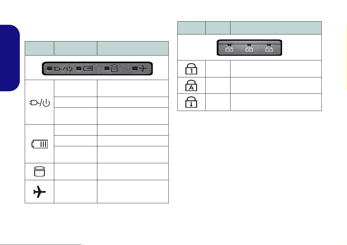
LED Indicators
The LED indicators on the computer display helpful information about the current status of the computer.
Icon Color Description
Icon Color Description
English
8
Orange
Green The Computer is On
Blinking Green
Orange The Battery is Charging
Green The Battery is Fully Charged
Blinking Orange
Green
Green
Table 2 - LED Power Indicators
The AC/DC Adapter is
Plugged In
The Computer is in Sleep
The Battery Has Reached
Critically Low Power Status
The Hard Disk/Optical
Device is in use
Airplane Mode is ON (the
WLAN, Bluetooth & 3G Mod-
ules are OFF)
Mode
Blue
Blue
Blue
Table 3 - LED Status Indicators
Number Lock (Numeric Keypad) Acti-
vated
Caps Lock Activated
Scroll Lock Activated
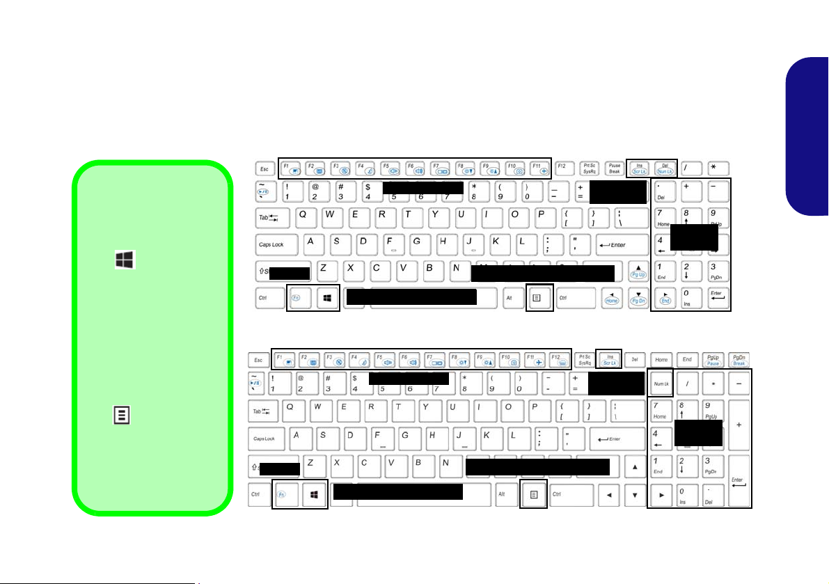
Keyboard
ad
Function Keys
Num Lk &
Scr Lk
Numeric
Keypad
Fn Key
Windows Logo Key
Windows Logo
Keyboard Shortcut
Use the Windows Logo
Key + D key combi-
nation to switch from the
Start screen to the Windows Desktop.
Menu/Application
Keyboard Shortcut
When the Desktop app
is running you can use
the Menu/Application
key on the keyboard
to act as a mouse rightclick. In the Start screen
this function is useful to
quickly display the Cus-
tomize bar.
Menu/Application Key
Function Keys
Num Lk &
Scr Lk
Numeric
Keypad
Fn Key
Windows Logo Key
Menu/Application Key
Models A & B
Models C & D
The keyboard has a numeric keypad for easy numeric data input. Pressing Fn + Num Lk (Models A & B)/Num Lk
(Models C & D) turns on/off the numeric keypad. It also features function keys to allow you to change operational features instantly.
(Illuminated keyboards Only) The keyboard illumination level may be adjusted, or turned off/on, by using the Fn +
F12 keys.
English
Figure 4 - Keyboard
9
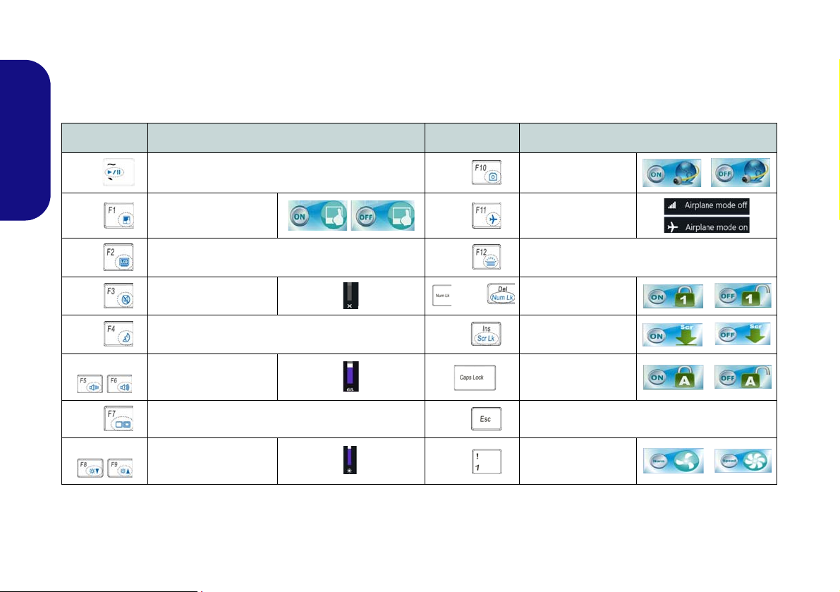
Function Keys & Visual Indicators
The function keys (F1 - F11 etc.) will act as hot keys when pressed while the Fn key is held down. In addition to the
basic function key combinations, some visual indicators are available (in the Windows Desktop application only and
not in the Start Screen) when the hot key driver is installed.
Keys Function/Visual Indicators Keys Function/Visual Indicators
English
Fn +
Fn + Touchpad Toggle Fn +
Fn +
Fn + M u te Toggle
Fn +
Fn +
Fn +
Fn +
Play/Pause (in Audio/Video Programs)
Turn LCD Backlight Off
(Press a key to or use Touchpad to turn on)
Sleep Toggle
Volume Decrease/
Increase
Change Display Configuration (see page 18)
Brightness Decrease/
Increase
Table 4 - Function Keys & Visual Indicators
Fn +
Fn +
/ Fn +
Fn +
Fn +
Fn +
PC Camera Power
Toggle
Airplane Mode Tog-
gle
Toggle Keyboard Illumination/Adjust Bright-
ness Level (Illuminated keyboards only)
Number Lock Toggle
Scroll Lock Toggle
Caps Lock Toggle
Control Center Toggle (see page 11)
Fan Automatic Con-
trol/ Full Power
10
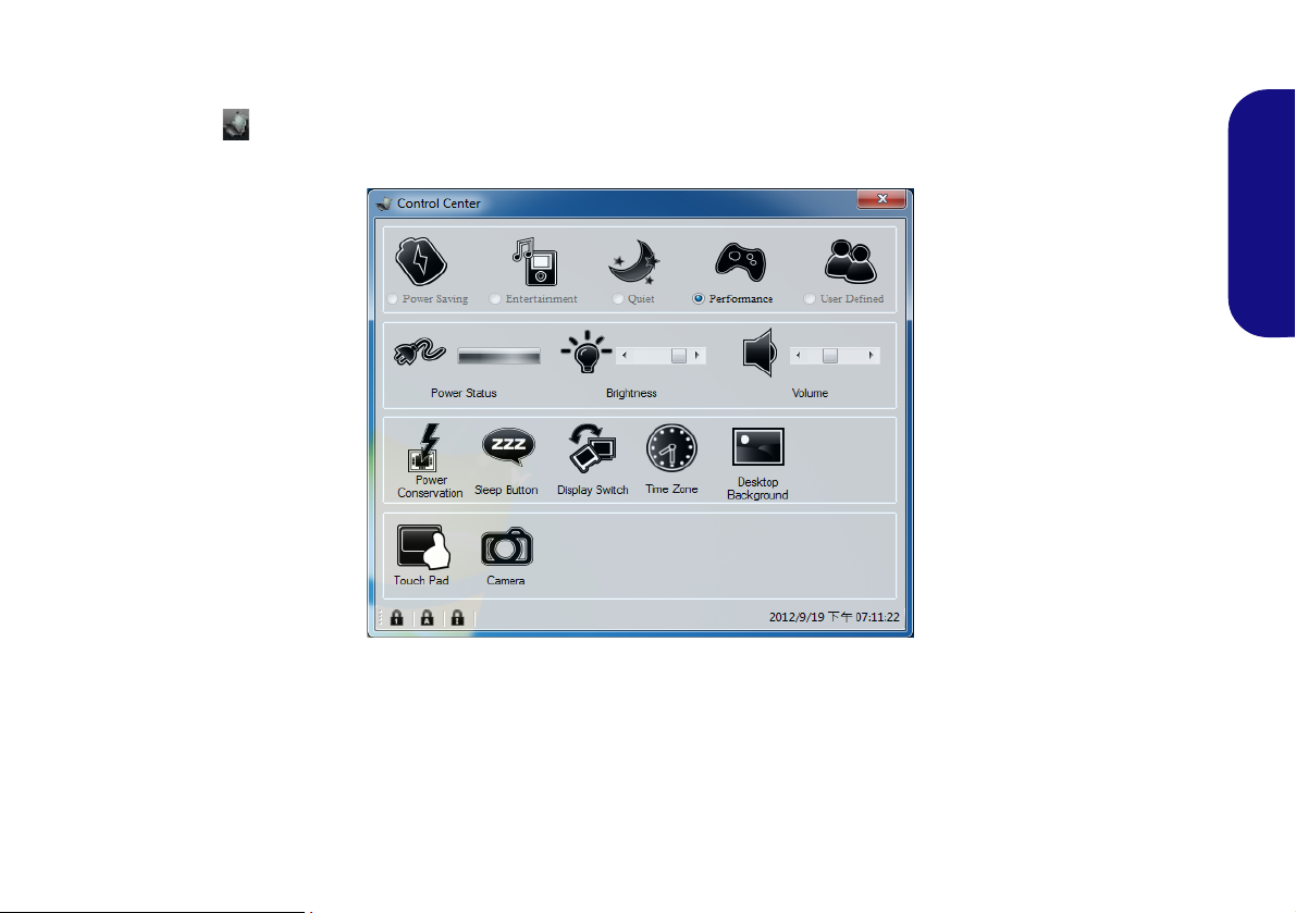
Control Center
When in the Windows Desktop application ( not in the Start Screen), press the Fn + Esc key combination, or doubleclick the icon in the notification area of the taskbar to toggle the Control Center on/off. The Control Center gives
quick access to frequently used controls, and enables you to quickly turn modules on/off.
Figure 5 - Control Center
English
Click on any button to turn any of the modules (e.g. TouchPad, Camera) on/off. Click on Power Conservation to switch
between Performance, Balanced or Energy Star modes. Click on the buttons (or just click and hold the mouse button)
to adjust the slider for Brightness/Volume. Click on Display Switch/Time Zone/ Desktop Background to bring up
the appropriate Windows control panel. Click on the Sleep button to put the computer into Hibernate or Sleep mode.
11
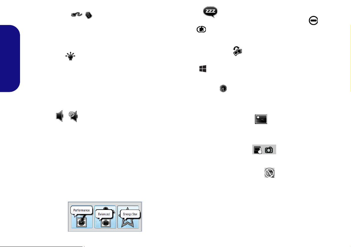
Power Status
The Power Status icon will show whether you are currently powered by the battery, or by the AC/DC adapter
plugged in to a working power outlet. The power status
bar will show the current battery charge state.
Brightness
The Brightness icon will show the current screen bright-
English
ness level. You can use the slider to adjust the screen
brightness or the Fn + F8/F9 key combinations, or use the
Fn + F2 key combination to turn off the LED backlight
(press any key to turn it on again). Note that screen brightness is also effected by the Power Mode selected.
Sleep
Click the Sleep button to bring up the Hibernate or
Sleep buttons, and click either button to have the
computer enter the appropriate power-saving mode.
Display Switch
Click the Display Switch button to access the menu (or
use the + P key combination) and select the appropriate display mode.
Time Zone
Clicking the Time Zone button will access the Date and
Time Windows control panel.
Volume
The Volume icon will show the current volume level. You
can use the slider to adjust the volume or the Fn + F5/F6
key combinations, or use the Fn + F3 key combination to
mute the volume.
Power Conservation
This system supports Energy Star power management
features that place computers (CPU, hard drive, etc.) into
a low-power sleep mode after a designated period of inactivity. Click either the Performance, Balanced or Ener-
gy Star button.
12
Desktop Background
Clicking the Desktop Background button will allow you
to change the desktop background picture.
Touchpad/PC Camera
Click either of these buttons to toggle the Touchpad or
camera module’s power status. A crossed out icon will appear over the top left of the icon when it is off
that the power status of the camera is also effected by the
Power Mode selected.
. Note
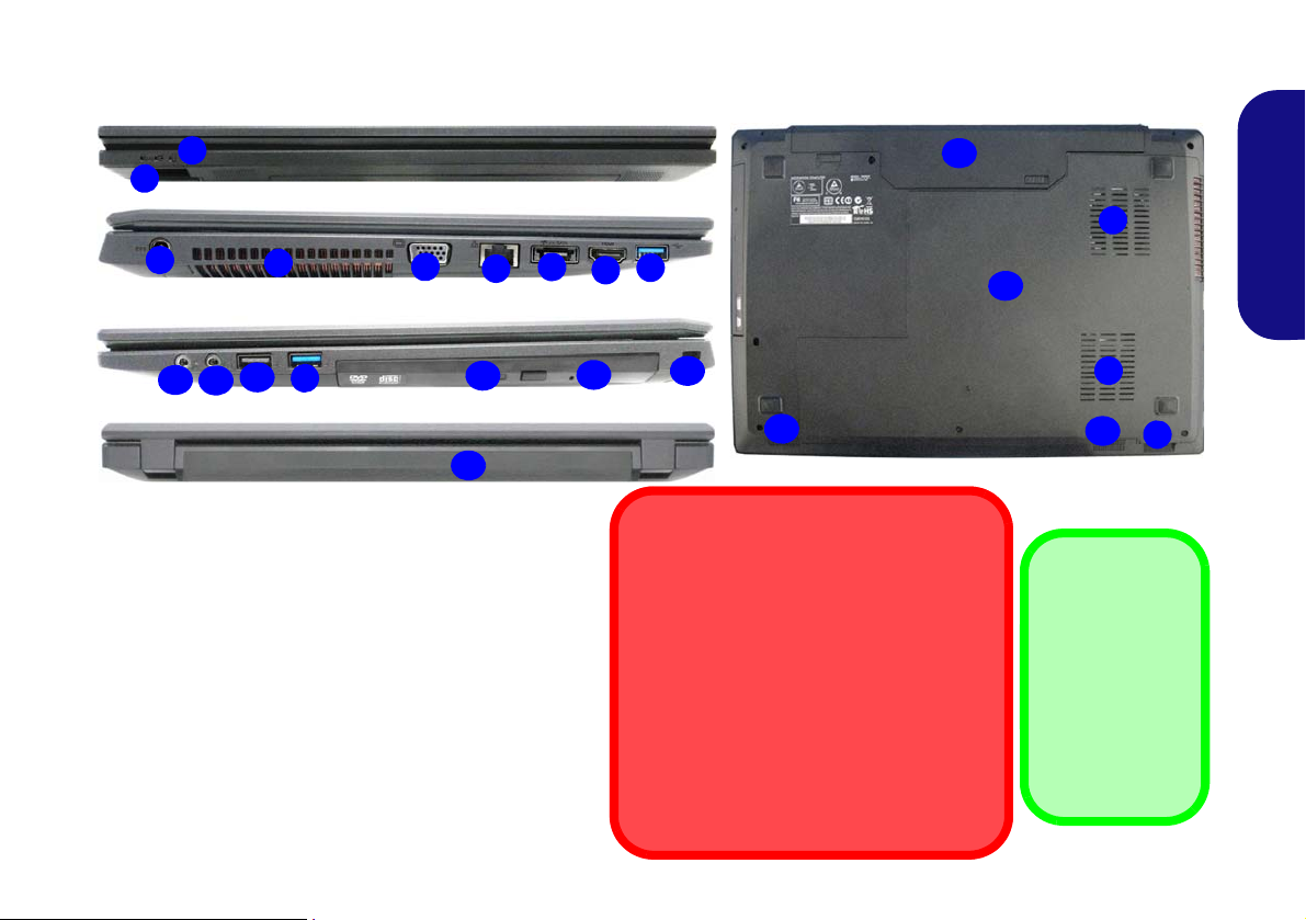
System Map: Front, Left, Right, Rear & Bottom Views
1
Front
14
Bottom
16
Figure 6 - Front, Left, Right, Rear & Bottom Views
(Models A & B)
1. LED Indicators
2. Multi-in-1 Card Reader
3. DC-In Jack
4. Vent
5. External Monitor Port
6. RJ-45 LAN Jack
7. Combined eSATA/USB
3.0 Port
8. HDMI-Out Port
9. USB 3.0 Ports
10. Microphone-In Jack
11. Headphone-Out Jack
12. USB 2.0 Port
13. Optical Device Drive
Bay
14. Emergency Eject Hole
15. Security Lock Slot
16. Battery
17. Component Bay Cover
18. Speakers
2
8
4
6
3
Left
Right
5
Rear
10
12
9
7
13
15
17
18
18
2
Overheating
To prevent your computer from overheating
make sure nothing blocks any vent while the
computer is in use.
Disc Emergency Eject
If you need to manually eject a disc (e.g. due
to an unexpected power interruption) you
may push the end of a straightened paper
clip into the emergency eject hole. Do not
use a sharpened pencil or similar object that
may break and become lodged in the hole.
USB 3.0 Port
USB 3.0 will
transfer data
much faster than
USB 2.0, and is
backwards-compatible with USB
2.0.
16
11
4
4
9
(Models A & B)
English
13
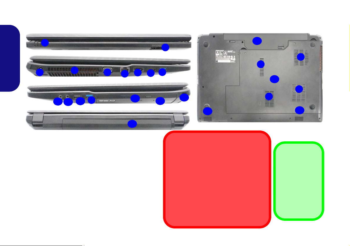
System Map: Front, Left, Right, Rear & Bottom Views
1
Front
14
Bottom
16
Figure 7 - Front, Left, Right, Rear & Bottom Views
(Models C & D)
1. LED Indicators
2. Multi-in-1 Card Reader
3. DC-In Jack
4. Vent
5. External Monitor Port
6. RJ-45 LAN Jack
7. Combined eSATA/USB
3.0 Port
8. HDMI-Out Port
9. USB 3.0 Ports
10. Microphone-In Jack
11. Headphone-Out Jack
12. USB 2.0 Port
13. Optical Device Drive Bay
14. Emergency Eject Hole
15. Security Lock Slot
16. Battery
17. Component Bay Cover
18. Speakers
2
8
4
6
3
Left
Right
5
Rear
10
12
9
7
13
15
17
4
18
18
Overheating
To prevent your computer from overheating
make sure nothing blocks any vent while the
computer is in use.
Disc Emergency Eject
If you need to manually eject a disc (e.g. due
to an unexpected power interruption) you
may push the end of a straightened paper
clip into the emergency eject hole. Do not
use a sharpened pencil or similar object that
may break and become lodged in the hole.
USB 3.0 Port
USB 3.0 will
transfer data
much faster than
USB 2.0, and is
backwards-compatible with USB
2.0.
16
11
9
4
4
4
(Models C & D)
English
14

Windows 8.1 Control Panel
Move the mouse to
the bottom left of the
screen and right-click
the Start button to access the menu.
Figure 8
Context
Menu
Figure 9
Start
Screen
Throughout this manual you will see an instruction to open the Control Panel. Right-click the Start button in the
Desktop app or Start screen (or use the Windows Logo Key + X key combination) to bring up an advanced context
menu of useful features such as Control Panel, Programs and Features, Power Options, Task Manager, Search, File Explorer, Command Prompt, Device Manager and Network Connections etc. and then select Control Panel.
Windows 8.1 Start Screen & Desktop
The Apps, control panels, utilities and programs within
Windows are accessed from the Start screen and/or
Windows Desktop app. The Desktop (which runs as an
app within the Start screen) can be accessed by clicking
the Desktop item in the Start screen (or by using the
Windows Logo Key + D key combination). The
taskbar is displayed at the bottom of the desktop screen,
and you can see the notification area of the taskbar in the
bottom right of the screen. Click the arrow at the bottom
of the Start screen to access Apps.
15
English
Apps & Tiles
Click the arrow at the bottom of the
screen to access Apps.
The Start screen will contain a number of apps, and many more
will be installed as you add more applications etc. Not all of these
apps can fit on one screen so you will often need use the slider at
the bottom of the screen in order to view all the necessary Apps.
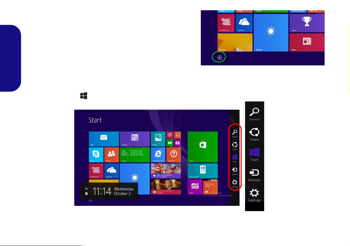
Charms Bar
English
The right side of the screen displays the Charms Bar. The Charms Bar contains the Search, Share, Start, Devices and
Settings menus. To access up the Charms Bar move the cursor to the upper or lower right corners of the screen, and
then hover over one of the items in the Charms Bar to activate it (the bar will be black when it is active), or use the
Windows Logo Key + C key combination.
16
Figure 10 - Start Screen with Charms Bar
Video Features
The system features both an Intel’s Integrated GPU (for
power-saving) and an NVIDIA’s discrete GPU (for performance). You can switch display devices, and configure
display options as long as the video drivers are installed.
Microsoft Hybrid Graphics
Microsoft Hybrid Graphics is a seamless technology
designed to get best performance from the graphics system while allowing longer battery life, without having to
manually change settings. The computer will automatically and seemlessly switch between the integrated UMA
(Unified Memory Architecture) GPU (iGPU) and the discrete GPU (dGPU) when required by the applications in
use.
To access the Display control panel in Windows:
1. Go to the Control Panel.
2. Click Display (icon) - in the Appearances and
Personalization category.
3. Click Adjust Screen Resolution/Adjust resolution.
OR
4. Right-click the desktop (use the Windows Logo Key + D
key combination to access the desktop) and select Screen
resolution.
5. Use the dropbox to select the screen resolution.
6. Click Advanced settings.
To access the Intel® HD Graphics Control Panel:
1. Click the icon (Intel® HD Graphics Control Panel) on the
Apps screen.
OR
2. Right-click the desktop (use the Windows Logo Key + D
key combination to access the desktop) and select Graphics
Properties from the menu.
OR
3. Click the icon in the notification area of the Desktop
taskbar and select Graphics Properties from the menu.
To access the NVIDIA Control Panel:
1. Go to the Control Panel.
2. Click NVIDIA Control Panel (icon) - in the Appearances and
Personalization category.
OR
3. Right-click the desktop (use the Windows Logo Key + D
key combination to access the desktop) and select NVIDIA
Control Panel from the menu.
English
17
Display Devices & Options
Screen Resolution for Apps (Windows 8.1)
The minimum resolution in which Apps will run is
1024x768.
The minimum resolution required to support all the features of Windows 8.1 (including multitasking with snap)
is 1366x768.
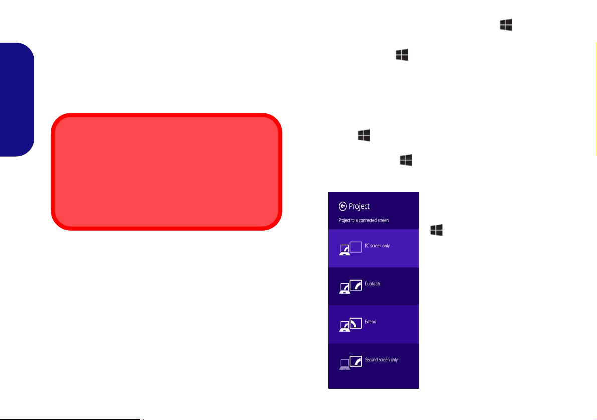
Figure 11
+ P (Change Display
Configuration)
Besides the built-in LCD you can also use an external
monitor/flat panel display/TV (TV through HDMI-Out
port only), connected to the external monitor port or to the
HDMI-Out port (High-Definition Multimedia Interface)
as your display device.
Using the Windows Logo Key + P Key Combination to Switch Displays
You can also use the + P key combination (or Fn + F7
) to quickly change display configuration and modes (this
is particularly useful when attaching a projector) in Win-
dows.
English
1. Attach your external display to the external monitor port/HDMIOut port, and turn it on.
2. Press the + P (or Fn + F7) key combination.
3. An on-screen menu will pop up.
4. Use the cursor keys ( + P) to select the appropriate
configuration from the menu, and press Enter to confirm the
selection.
18
Audio Features
Volume Adjustment
The sound volume level can also be set using the volume control in the Settings menu
in the Charms Bar (on the Start screen) or
the Speaker icon in the desktop taskbar.
Sound Blaster
Cinema & HDMI
Note that the Sound
Blaster Cinema audio
effects do not apply to
audio generated
through an HDMI connection.
You can configure the audio options on your computer
from the Sound control panel in Windows, from the
HD VDeck icon on the desktop or VIA HD Audio Deck
control panel.
The volume may be adjusted by means of the Fn + F5/F6
key combination or the volume icon in the taskbar.
Sound Blaster Cinema EQ
Install the Sound Blaster Cinema application to allow
you to configure the audio settings to your requirements
for the best performance in games, music and movies.
English
Creative Software AutoUpdate
Run the application from the shortcut in the Apps screen
and make sure you are connected to the internet, then click
Next and follow the on screen instructions to update the
software.
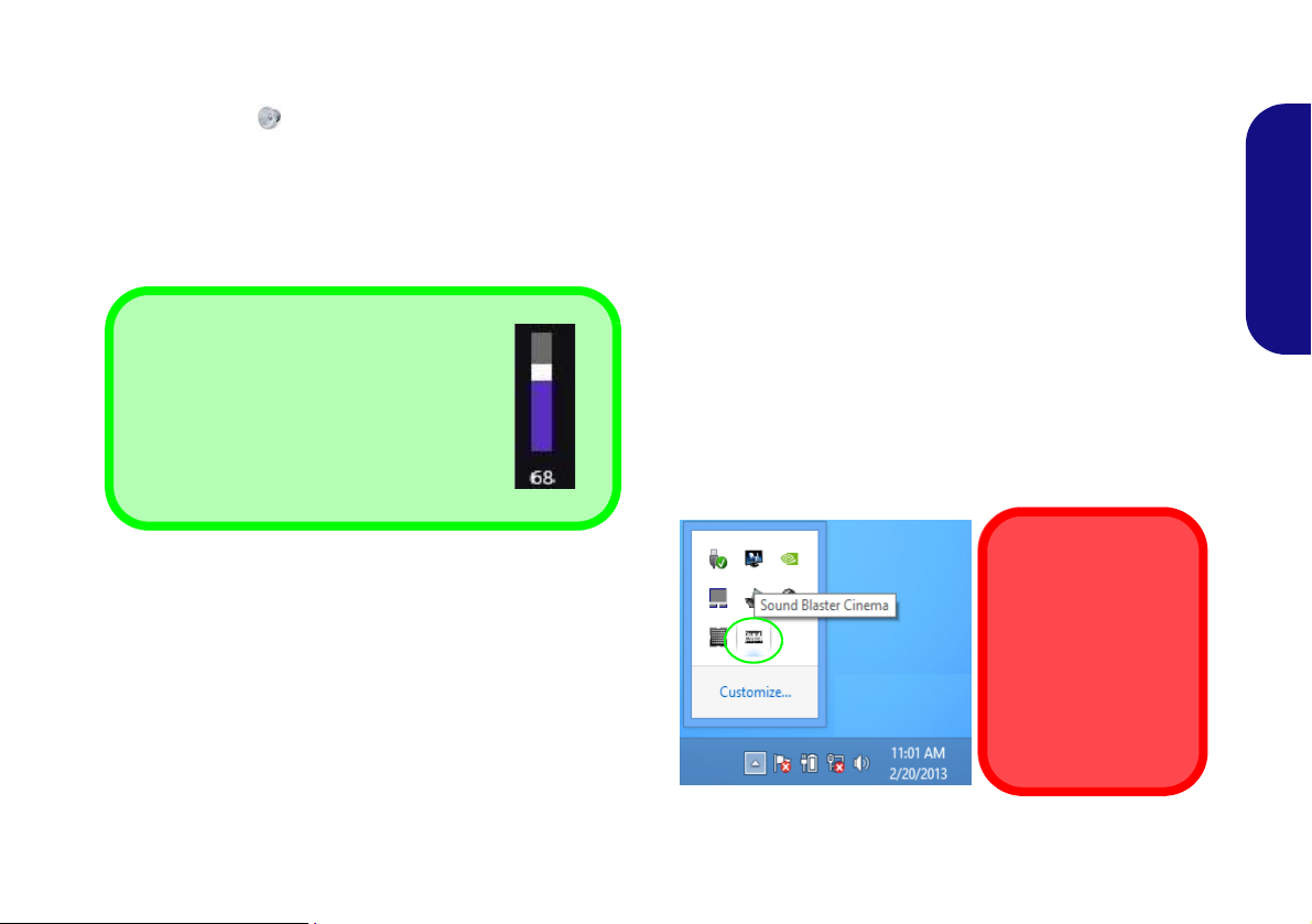
Sound Blaster Cinema Application
Run the Sound Blaster Cinema control panel from the
notification area of the taskbar (or from the item in the
Apps screen). Click on the tabs to access any of the control panel menus.
Figure 12 - Sound Blaster Cinema
(Taskbar Notification Area Icon)
19
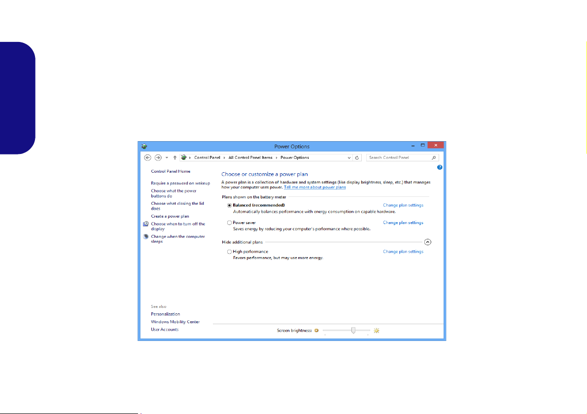
Power Options
Figure 13 - Power Options
The Power O ptions (Hardware and Sound menu) control panel icon in Windows allows you to configure power management features for your computer. You can conserve power by means of power plans and configure the options for
the power button, sleep button (Fn + F4), computer lid (when closed), display and sleep mode (the default power
saving state) from the left menu. Note that the Power saver plan may have an affect on computer performance.
Click to select one of the existing plans, or click Create a power plan in the left menu and select the options to create
a new plan. Click Change Plan Settings and click Change advanced power settings to access further configuration
English
options.
20
Driver Installation
Driver Installation General
Guidelines
As a general guide follow the
default on-screen instructions for each driver (e.g.
Next > Next > Finish) unless
you are an advanced user. In
many cases a restart is required to install the driver.
Make sure any modules (e.g.
WLAN or Bluetooth) are ON
before installing the appropriate driver.
Windows Update
After installing all the drivers
make sure you enable Win-
dows Update in order to get
all the latest security updates
etc. (all updates will include
the latest hotfixes from Mi-
crosoft).
Driver Installation & Power
When installing drivers make sure
your computer is powered by the
AC/DC adapter connected to a
working power source. Some drivers draw a significant amount of
power during the installation procedure, and if the remaining battery
capacity is not adequate this may
cause the system to shut down and
cause system problems (note that
there is no safety issue involved
here, and the battery will be rechargeable within 1 minute).
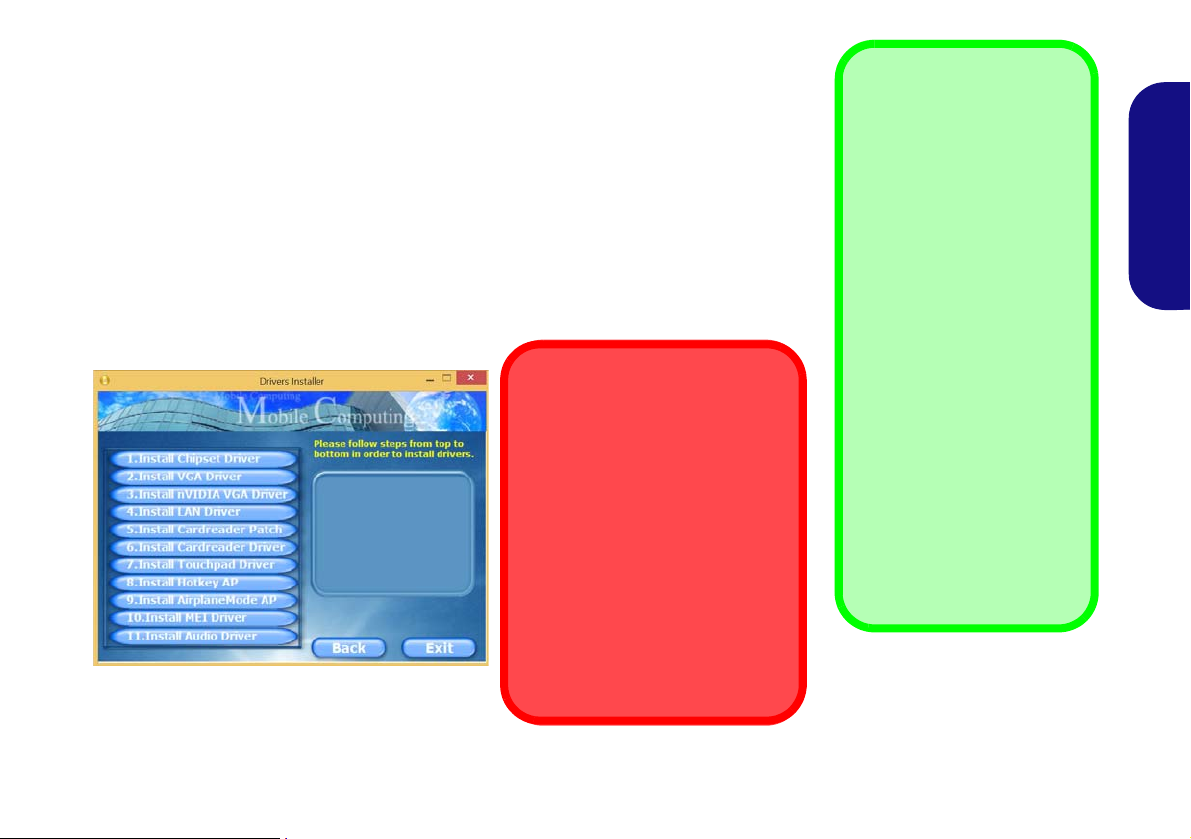
The Device Drivers & Utilities + User’s Manual disc contains the drivers and utilities
necessary for the proper operation of the computer. This setup will probably have already been done for you. If this is not the case, insert the disc and click Install Drivers
(button), or Option Drivers (button) to access the Optional driver menu. Install the
drivers in the order indicated in Figure 14. Click to select the drivers you wish to
install (you should note down the drivers as you install them). Note: If you need to
reinstall any driver, you should uninstall the driver first
If the Found New Hardware wizard appears during the installation procedure, click
Cancel to close the window, and follow the installation procedure as directed.
Figure 14 - Install Drivers
.
English
21

3G Module
1
Model A
USIM Card
Orientation
Note that the USIM
card’s readable side
(with the gold-colored
contacts) should face
upwards as illustrated.
1
1
(Optional for Models A & B Only)
If you have included an optional 3G module in your purchase option, follow the instructions below to install the USIM
card (which will be provided by your service provider), and then run the appropriate application supplied with your
module.
USIM Card Insertion
1. Turn off the computer, and turn it over and remove the battery (slide the latches in the direction indicated below and slid e the b at-
English
tery out).
2. Insert the USIM card as illustrated below until it clicks into position, and replace the battery.
Figure 15 - Remove the battery and Insert the USIM Card
22
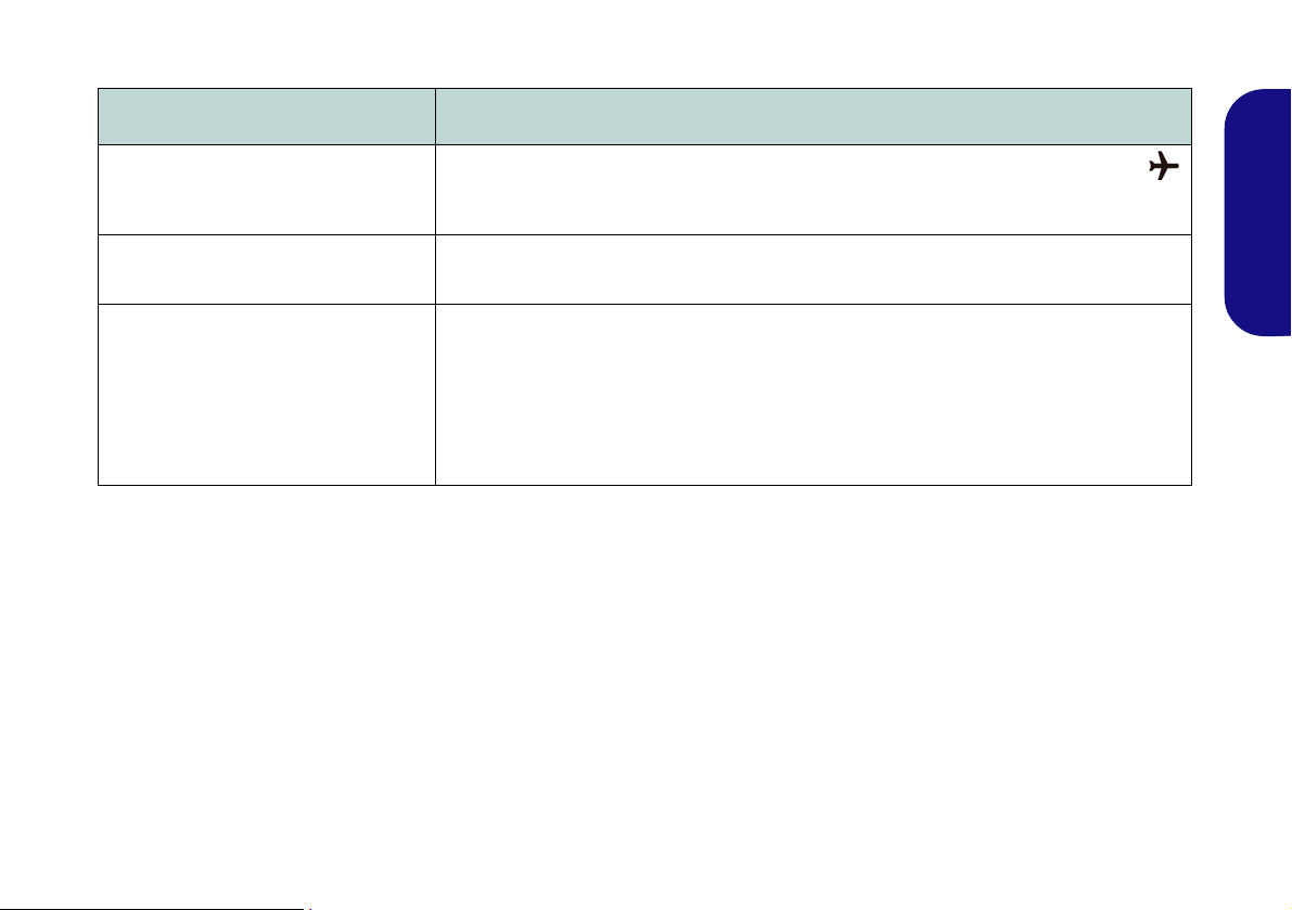
Troubleshooting
Problem Possible Cause - Solution
The Wireless LAN/Bluetooth
modules cannot be detected.
The PC Camera module cannot be
detected.
The captured video files from the PC
Camera are taking up too much disk
space.
The modules are off as the computer is in Airplane Mode. Check the LED in dicator
and/or function key indicator to see if it is in Airplane Mode (see Table 2 on page 8). Use
the Fn + F11 key combination to toggle Airplane Mode on/off (see Table 4 on page 10).
The module is off. Press the Fn + F10 key comb inati on in order to enab le th e module (see
Table 4 on page 10). Run the camera application to view the camera picture.
Note that capturing high resolution video files requires a substantial amount of disk space
for each file.
Note that the Windows system requires a minimum of 20GB (64bit) of free space on the
C: drive system partition. It is recommended that you save the capture video file to a
location other than the C:drive, limit the file size of the captured video or reduce video
resolution.
English
23

Specifications
Latest Specification Information
The specifications listed in this here
are correct at the time of going to
press. Certain items (particularly processor types/speeds) may be
changed, delayed or updated due to
the manufacturer's release schedule. Check with your service center
for details.
English
Processor Options
Models A & C:
Intel® Core™ i7 Processor
i7-4900MQ (2.80GHz)
8MB L3 Cache, 22nm, DDR3L-1600MHz,
TDP 47W
i7-4800MQ (2.70GHz), i7-4700MQ
(2.40GHz)
6MB L3 Cache, 22nm, DDR3L-1600MHz,
TDP 47W
i7-4600M (2.9GHz)
4MB L3 Cache, 22nm, DDR3L-1600MHz,
TDP 37W
Intel® Core™ i5 Processor
i5-4330M (2.80GHz), i5-4300M (2.60GHz),
i5-4200M (2.50GHz)
3MB L3 Cache, 22nm, DDR3L-1600MHz,
TDP 37W
24
Intel® Core™ i3 Processor
i3-4100M (2.50GHz), i3-4000M (2.40GHz)
3MB L3 Cache, 22nm, DDR3L-1600MHz,
TDP 37W
Intel® Pentium® Processor
3550M (2.30GHz)
2MB L3 Cache, 22nm, DDR3L-1600MHz,
TDP 37W
Models B & D:
Intel® Core™ i7 Processor
i7-4900MQ (2.80GHz)
8MB L3 Cache, 22nm, DDR3L-1600MHz,
TDP 47W
i7-4800MQ (2.70GHz), i7-4700MQ
(2.70GHz),
6MB L3 Cache, 22nm, DDR3L-1600MHz,
TDP 47W
i7-4600M (2.9GHz)
4MB L3 Cache, 22nm, DDR3L-1600MHz,
TDP 37W
Intel® Core™ i5 Processor
i5-4330M (2.80GHz), i5-4300M (2.60GHz),
i5-4200M (2.50GHz)
3MB L3 Cache, 22nm, DDR3L-1600MHz,
TDP 37W
Intel® Core™ i3 Processor
i3-4100M (2.50GHz), i3-4000M (2.40GHz)
3MB L3 Cache, 22nm, DDR3L-1600MHz,
TDP 37W
Core Logic
Intel® HM86 Chipset
BIOS
48Mb SPI Flash ROM
AMI BIOS
Memory
Two 204 Pin SO-DIMM Sockets Supporting
DDR3L 1600MHz Memory
Memory Expandable up to 16GB
(The real memory operating frequency
depends on the FSB of the processor.)
Storage
(Factory Option) One 12.7mm(h) Optical
Device Type Drive (Super Multi Drive/BluRay Combo Drive/Blu-Ray Writer Drive)
(Factory Option) 2.5" 9.5mm 2nd HDD
caddy
One Changeable 2.5" 9.5mm/7.0mm (h)
SATA HDD
(Factory Option) One mSATA Solid State
Drive (SSD)
LCD
Models A & B:
15.6" (39.62cm) HD / FHD
Models C & D:
17.3" (43.94cm) HD+ / FHD

Video Adapter
Intel® Integrated GPU and NVIDIA®
Discrete GPU
Supports Microsoft Hybrid Graphics
Models A & C:
Intel Integrated GPU (GPU is Dependent
on Processor)
Intel® HD Graphics 4600/Intel® HD
Graphics
Dynamic Frequency (Intel Dynamic Video
Memory Technology for up to 1.7GB)
Microsoft DirectX®11 Compatible
NVIDIA® Discrete GPU
NVIDIA® GeForce 840M
2GB GDDR3 Video RAM on board
Microsoft DirectX® 11.1 Compatible
Models B & D:
Intel Integrated GPU (GPU is Dependent
on Processor)
Intel® HD Graphics 4600/Intel® HD
Graphics
Dynamic Frequency (Intel Dynamic Video
Memory Technology for up to 1.7GB)
Microsoft DirectX®11 Compatible
NVIDIA® Discrete GPU
NVIDIA® GeForce GTX 850M
2GB GDDR3 Video RAM on board
Microsoft DirectX® 11.1 Compatible
Audio
High Definition Audio Compliant Interface
2 * Built-In Speakers
Built-In Microphone
Sound Blaster™ Cinema
Security
Security (Kensington® Type) Lock Slot
BIOS Password
Keyboard
Models A & B:
Full-size “WinKey” keyboard (with numeric
keypad)
Models C & D:
Full-size “WinKey” keyboard (with numeric
keypad)
(Factory Option) Illuminated Full-size
“WinKey” keyboard (with numeric keypad)
Pointing Device
Built-in Touchpad
Interface
One USB 2.0 Port
Two USB 3.0 Ports
One eSATA Port (USB 3.0 Combo)
One HDMI-Out Port
One External Monitor Port
One Headphone-Out Jack
One Microphone-In Jack
One RJ-45 LAN Jack
One DC-in Jack
Mini Card Slots
Models A & B:
Slot 1 for WLAN Module or WLAN and
Bluetooth Combo Module
(Factory Option) Slot 2 for 3G Module or
mSATA SSD
Models C & D:
Slot 1 for WLAN Module or WLAN and
Bluetooth Combo Module
(Factory Option) Slot 2 for mSATA SSD
Card Reader
Embedded Multi-In-1 Card Reader
MMC (MultiMedia Card) / RS MMC
SD (Secure Digital) / Mini SD / SDHC/
SDXC
MS (Memory Stick) / MS Pro / MS Duo
English
25

Communication
Built-In Gigabit Ethernet LAN
1.0M HD PC Camera Module
(Factory Option) 2.0M FHD PC Camera
Module
(Factory Option - Models A & B Only) 3G
Mini-Card Module
English
WLAN/ Bluetooth Half Mini-Card
Modules:
(Factory Option) Intel® Wireless-AC 7260
Wireless LAN (802.11a/c) + Bluetooth 4.0
(Factory Option) Intel® Wireless-N 7260
Wireless LAN (802.11a/g/n) + Bluetooth 4.0
(Factory Option) Intel® Wireless-N 7260
Wireless LAN (802.11b/g/n)
(Factory Option) Third-Party Wireless LAN
(802.11b/g/n)
(Factory Option) Third-Party Wireless LAN
(802.11b/g/n) + Bluetooth 4.0
Environmental Spec
Temperature
Operating: 5
Non-Operating: -20°C - 60°C
Relative Humidity
Operating: 20% - 80%
Non-Operating: 10% - 90%
°C - 35°C
Power
Models A & C:
Full Range AC/DC Adapter
AC Input: 100 - 240V, 50 - 60Hz
DC Output: 19V, 4.74A (90W)
(Factory Option) 6 Cell Smart Lithium-Ion
Battery Pack, 62.16WH
(Factory Option) 6 Cell Smart Lithium-Ion
Battery Pack, 48.84WH
Models B & D:
Full Range AC/DC Adapter
AC Input: 100 - 240V, 50 - 60Hz
DC Output: 19.5V, 6.15A (120W)
(Factory Option) 6 Cell Smart Lithium-Ion
Battery Pack, 62.16WH
(Factory Option) 6 Cell Smart Lithium-Ion
Battery Pack, 48.84WH
Dimensions & Weight
Models A & B:
374mm (w) * 252mm (d) * 14 - 31.4mm (h)
OR
374mm (w) * 249.5mm (d) * 14.8 - 32.8mm
(h)
2.5kg (with ODD and 62.16WH Battery)
Models C & D:
413mm (w) * 272.8mm (d) * 36.4mm (h)
3.1kg (with ODD and 62.16WH Battery)
26

Über das Ausführliche Benutzerhandbuch
Diese Kurzanleitung soll einen Überblick über die Schritte geben, die dazu notwendig s ind, das System zu starten. Dieses ist
nur eine Ergänzung und kein Ersatz für das erweiterte englischsprachige Benutzerhandbuch, das auf der mitgelieferten Disc
Device Drivers & Utilities + User's Manual im Adobe-Acrobat-Format vorliegt. Diese Disc enthält auch die Treiber und
Utility-Programme, die für einen einwandfreien Betrieb des Computers notwendig sind (Hinweis: Das Unternehmen behält
sich das Recht vor, diese Publikation ohne Vorankündigung zu überarbeiten und den Inhalt zu verändern).
Einige oder alle Funktionen des Computers sind bereits eingerichtet worden. Falls das nicht der Fall ist oder wenn Sie einzelne Teile des Systems neu konfigurieren (oder neu installieren) möchten, finden Sie eine Anleitung im erweiterten Benut-
zerhandbuch. Die Disc Device Drivers & Utilities + User's Manual enthält nicht das Betriebssystem.
Einhaltung gesetzlicher Vorschriften und Sicherheitshinweise
Beachten Sie sorgfältig die Hinweise zu gesetzlichen Vorschriften und zu Sicherheitshinweisen im erweiterten Benutzerhandbuch auf der Disc Device Drivers & Utilities + User's Manual.
© Januar 2014
Warenzeichen
Intel, Intel Core und Pentium sind warenzeichen/eingetragenes warenzeichen der Intel Corporation.
Deutsch
27

Hinweise zu Pflege und Betrieb
Das Notebook ist zwar sehr stabil, kann aber dennoch beschädigt werden. Damit es nicht dazu kommt, sollten Sie die
folgenden Hinweise beachten:
• Das Gerät darf nicht herunterfallen und in anderer Form Stößen
ausgesetzt werden. Wenn der Computer fällt, können das Gehäuse und
andere Komponenten beschädigt werden.
• Das Gerät darf nicht nass werden und sich nicht überhitzen. Computer und Netzteil dürfen nicht in der Nähe von Wärmequellen stehen oder
gelagert werden. Dies ist ein elektrisches Gerät. Wenn Wasser oder
andere Flüssigkeiten eindringen, kann der Computer stark beschädigt
werden.
• Vermeiden Sie Interferenzen mit anderen Geräten. Halten Sie den
Computer fern von magnetischen Feldern, die von Stromquellen, Moni-
Deutsch
toren, Magneten etc. erzeugt werden. Die können die Leistung beeinträchtigen und Ihre Daten beschädigen.
• Achten Sie auf die richtige Bedienung des Computers. Schalten Sie
ihn erst aus, wenn alle Programme geschlossen wurden (speichern Sie
Ihre Daten!). Speichern Sie regelmäßig Ihre Daten, da diese verloren
gehen können, wenn der Akku verbraucht ist.
Reparatur
Nehmen Sie vor dem Reinigen des Wenn Sie versuchen, den
Computer selbst zu reparieren , können Ihre Garantieansprüche
verloren gehen. Außerdem besteht Stromschlaggefahr für Ihre
Gesundheit und das Gerät durch frei liegende Teile. Lassen Sie
Reparaturarbeiten nur von qualifizierten Reparaturfachleuten
durchführen, insbesondere wenn folgende Umstände vorliegen:
• Wenn das Netzkabel oder der AC/DC-Adapter beschädigt oder ze rsch l is sen sind.
• Wenn der Computer Regen ausgesetzt war oder mit Flüssigkeiten in
Berührung gekommen ist.
• Wenn der Computer unter Beachtung der Bedienungsanweisungen nicht
korrekt arbeitet.
• Wenn der Computer heruntergefallen ist oder beschädigt wurde (berühren Sie nicht die giftige Flüssigkeit des LCD-Bildschirms).
• Wenn ein ungewöhnlicher Geruch, Hitze oder Rauch aus dem Computer
entweicht.
Sicherheitsinformationen
• Verwenden Sie nur einen AC/DC-Adapter, der für die Verwendung mit
diesem Computer zugelassen ist.
• Verwenden Sie nur das Netzkabel und die Akkus, die in diesem Benutzerhandbuch spezifiziert sind
Sie können explodieren. Richten Sie sich nach den regional gültigen Entsorgungsvorschriften.
• Verwenden Sie den Akku nicht mehr, wenn er heruntergefallen ist oder in
anderer Weise beschädigt (z.B. verzogen) ist. Auch wenn der Computer
mit dem beschädigten Akku zu funktionieren schein, können dadurch
Stromkreise beschädigt werden, die schließlich einen Brand verursachen
können.
• Achten Sie darauf, dass Ihr Computer ausgeschaltet ist, wenn Sie es fur
den Transport z.B. wahrend einer Reise in eine Tasche einpakken.
• Nehmen Sie vor dem Reinigen des Computers den Akku heraus, und
trennen Sie es von allen externen Stromquellen, Peripheriegeräten und
Kabeln (einschließlich Telefonkabel) ab.
• Reinigen Sie den Computer mit einem weichen, sauberen Tuch. Tragen
Sie das Reinigungsmittel nicht direkt auf den Computer auf. Verwenden
Sie keine flüchtigen Reinigungsmittel (Petroleumdestillate) oder Scheuermittel zum Reinigen des Computers.
• Versuchen Sie nicht, Akkus zu reparieren. Lassen Sie die Akkupacks
durch den Servicevertreter oder qualifiziertes Fachpersonal reparieren
oder austauschen.
• Beachten Sie, dass das Logo bei den Computern, die über ein galvanisch
beschichtetes LCD-Logo verfügen, von einer Schutzfolie bedeckt ist.
Durch die natürliche Abnutzung kann diese Schutzfolie beschädigt werden oder abgehen und die scharfen Kanten des frei liegenden Logos
freigeben. Seien Sie in solch einem Fall vorsichtig bei der Handhabung
des Computers, und vermeiden Sie es, das herausstehende beschichtete
LCD-Logo zu berühren. Legen Sie keine Gegenstände in die Tragetasche, da diese während des Transports gegen den Computer drücken
können. Wenden Sie sich in einem solchen Fall von Abnutzung an Ihr
Service Center.
. Entsorgen Sie die Akkus nicht in Feuer.
28

Polymer Akku Sicherheitshinweise
Entsorgen der Akkus/ Batterien & Achtung
Das von Ihnen gekaufte Produkt enthält einen aufladbaren
Akku. Dier Akku ist wiederverwertbar. Nach verschiedenen nationalen und regionalen Getzgebungen kann es verboten in,
einen nicht mehr gebrauchsfähigen Akku in den normalen
Hausmüll zu werfen. Informieren Sie sich bei Ihrem regionalen
Entsorgungsunternehmen über Recycling-Möglichkeiten oder
korrekte Entsorgung.
Wenn ein falscher Akku eingesetzt wird, besteht Explosionsgefahr. Tauschen Sie den Akku nur durch den gleichen oder einen
baugleichen Typ aus, der vom Hersteller empfohlen wird. Entsorgen Sie den verbrauchten Akku entsprechend der Anweisungen des Herstellers.
Beachten Sie die folgenden Hinweise, die sich speziell auf Polymer Akkus beziehen. Diese Hinweise haben zudem Vorrang
gegenüber den Allgemeinen Akku Sicherheitshinweisen.
• Polymer Akkus können sich etwas ausdehnen oder anschwellen. Dies ist
Teil des Sicherheitsmechanismus des Akkus und kein Anlass zur Sorge.
• Seien Sie vernünftig im Umgang mit Polymer Akkus. Verwenden Sie
keine Polymer Akkus in Umgebungen mit hohen Temperaturen und
lagern Sie keine ungenutzten Akkus über längere Zeiträume.
Deutsch
29

Schnellstart
Herunterfahren
Bitte beachten Sie, daß der Computer immer
mit dem Befehl Herunterfahren in Windows
(siehe unten) heruntergefahren werden muß.
Dadurch werden Festplatten- bzw. Systemprobleme vermieden.
Klicken auf Einstellungen in der CharmsLeiste aus (die Charms-Leiste wird aufgerufen, indem Sie die Windows Logo-Taste
und gleichzeitig auf C drücken). Wählen
Sie dann aus dem
Ein/Aus-Menü die Option
Herunterfahren.
Oder
Wählen Sie aus dem Kontextmenü Herun-
terfahren oder abmelden > Herunterfahren (das Kontextmenü wird aufgerufen,
indem Sie die Windows Logo-Taste
und gleichzeitig auf X drücken).
130°
Abb. 1 - Öffnen des
Dekkels/LCD/Computers
mit angeschlossenem
AC/DC-Adapter
1. Entfernen Sie das gesamte Verpackungsmaterial.
2. Legen Sie den Computer auf eine stabile
Unterlage.
3. Setzen Sie den Akku ein, und stellen Sie sicher,
dass sie fest sitzt.
4. Schließen Sie alle Peripheriegeräte, die Sie mit
dem Computer verwenden wollen (z. B. Tastatur
und Maus), an die entsprechenden Schnittstellen
an.
5. Schließen Sie den AC/DC-Adapter an die DC-
Eingangsbuchse an der linken Seite des
Computers an. Verbinden Sie dann das
Netzkabel mit einer Netzsteckdose und dem AC/
Deutsch
DC-Adapter.
6. Klappen Sie den Deckel/LCD vorsichtig mit einer
Hand auf, und öffnen Sie ihn auf einen
angenehmen Sichtwinkel (jedoch nicht weiter als
130°). Mit der anderen Hand halten Sie das
Unterteil des Computers fest (siehe Abb. 1)
(Hinweis: Heben Sie den Computer niemals am
Deckel/LCD hoch).
7. Drücken Sie auf den Netzschalter, um den
Computer einzuschalten.
Systemsoftware
Möglicherweise wurde das Notebook bereits
mit vorinstallierter Software ausgeliefert. Ist
das nicht der Fall, oder wenn Sie das Notebook
für ein anderes System neu konfigurieren
möchten, finden Sie dazu eine Anleitung in diesem Handbuch zu Microsoft Windows 8.1.
30

Modellunterschiede
Diese Notebookserie umfasst veir verschiedene Modelltypen, die sich hauptsächlich in Folgendem unterscheiden.
Funktion Modell A Modell B Modell C Modell D
Videoadapter
LCD
3G Modul
Stromversorgung
Integrierte GPU von Intel®
(Intel® HD Graphics 4600/
Intel® HD Graphics) und
Diskrete GPU von
NVIDIA® (NVIDIA®
GeForce
DC-Ausgang: 19V, 4,74A
840M
)
15,6" (39,62cm) HD/FHD 17,3" (43,94cm) HD+/FHD
Option Nein
(90W)
Integrierte GPU von
Intel® (Intel® HD Gra-
phics 4600/Intel® HD
Graphics) und Diskrete
GPU von NVIDIA®
(NVIDIA® GeForce GTX
850M
)
DC-Ausgang: 19,5V,
6,15A (120W)
Intel® (Intel® HD Gra-
phics 4600/Intel® HD
Graphics) und Diskrete
DC-Ausgang: 19V , 4,74A
Tabelle 1 - Modellunterschiede
Integrierte GPU von
GPU von NVIDIA®
(NVIDIA® GeForce
840M
)
(90W)
Integrierte GPU von
Intel® (Intel® HD Gra-
phics 4600/Intel® HD
Graphics) und Diskrete
GPU von NVIDIA®
(NVIDIA® GeForce GTX
850M
)
DC-Ausgang: 19,5V,
6,15A (120W)
Deutsch
31

Systemübersicht: Ansicht von vorne mit geöffnetem LCD-Bild-
Beachten Sie, dass der
Funktionsbereich des
Touchpads und der Tasten
innerhalb der rot gepunkteten Linien liegt.
Abb. 2
Ansicht von vorne mit geöffnetem
LCD-Bildschirm (Modelle A & B)
1. PC-Kamera
2. Mikrofon
3. *LED der PC-Kamera
*Wenn die PC-Kamera verwendet
wird, leuchtet die LED rot.
4. LCD-Bildschirm
5. Netzschalter
6. LED-Anzeigen
7. Tastatur
8. Touchpad mit Tasten
Die Benutzung drahtlos
angeschlossener Geräte in
Flugzeugen
In der Regel ist die Benutzung jeglicher
tragbarer elektronischer Funkgeräte in
Flugzeugen verboten.
Stellen Sie sicher, dass das WLANund das Bluetooth-Modul durch Aktivieren des Flugzeugmodus ausgeschaltet
sind, wenn Sie sich an Bord eines Flugzeugs befinden.
5
7
6
2
1
3
4
8
8
schirm (Modelle A & B)
Deutsch
32

Systemübersicht: Ansicht von vorne mit geöffnetem LCD-Bild-
Abb. 3
Ansicht von vorne mit geöffnetem
LCD-Bildschirm (Modelle C & D)
1. PC-Kamera
2. Mikrofon
3. *LED der PC-Kamera
*Wenn die PC-Kamera verwendet
wird, leuchtet die LED rot.
4. LCD-Bildschirm
5. Netzschalter
6. LED-Anzeigen
7. Tastatur
8. Clickpad/Touchpad
Die Benutzung drahtlos
angeschlossener Geräte in
Flugzeugen
In der Regel ist die Benutzung
jeglicher tragbarer elektronischer
Funkgeräte in Flugzeugen verboten.
Stellen Sie sicher, dass das
WLAN- und das Bluetooth-Modul
durch Aktivieren des Flugzeugmodus ausgeschaltet sind, wenn Sie
sich an Bord eines Flugzeugs
befinden.
5
7
6
2
1
3
4
8
8
Empfindlichkeit des
Clickpads/
Touchpads
Der Maustasten-Bereich befindet sich ca.
15 mm über der unteren Kante des Pads.
Die Trennlinie zwischen der linken und
rechten Maustaste verläuft ungefähr in der
Mitte (siehe unten).
Drücken Sie für einen
Linksklick auf den linken Maustastenbereich und für einen
Rechtsklick auf den
rechten Maustastenbereich.
schirm (Modelle C & D)
Deutsch
33

LED-Anzeigen
Die LED-Anzeigen auf dem Computer zeigen wichtige
Informationen über den aktuellen Status des Computers.
Symbol Farbe Beschreibung
Symbol Farbe Beschreibung
Blau Die Nummerntastatur ist aktiviert
Deutsch
34
Orange
Grün Der Computer ist angeschaltet
Lampe
blinkt grün
Orange Der Akku wird geladen
Grün Der Akku ist voll geladen
Lampe
blinkt
orange
Grün
Grün
Tabelle 2 - LED-Stromanzeigen
Der AC/DC-Adapter ist ange-
schlossen
Das System ist im konfigurierten
Energiesparmodus
Der Akku hat einen kritisch niedri-
gen Stromstatus erreicht
Es wird auf die Festplatte/das
optische Laufwerk zugegriffen
Flugzeugmodus ist EIN (das
WLAN-, das 3G- und das Blu-
etooth-Modul ausgeschaltet sind)
Blau Caps-Lock ist aktiviert
Blau Scroll-Lock ist aktiviert
Tabelle 3 - LED-Statusanzeigen

Keys
Numeric
Keypad
Keypad
Windows-Logo-Taste
Menü/Anwendungstaste
Tastenkürzel
Windows-Logo
Drücken Sie gleichzeitig
auf die Windows Logo-
Taste und die Taste
D, um vom Start-Bild-
schirm zum WindowsDesktop zu wechseln.
Tastenkürzel Menü/
Anwendung
Wenn die Desktop-App
läuft, funktioniert die
Menü/Anwendungtaste
auf der Tastatur
wie ein Rechtsklick mit
der Maustaste. Auf dem
Start-Bildschirm ist diese
Funktion sehr nützlich,
um direkt auf die Leiste
Anpassen zuzugreifen.
Fn Taste
Funktionstasten
Num &
Rollen
Nummemtastatur
Windows-Logo-Taste
Menü/Anwendungstaste
Fn Taste
Funktionstasten
Num &
Rollen
Nummemtastatur
Modelle A & B
Modelle C & D
Tastatur
Die Tastatur hat eine eingebettete Nummerntastatur für einfache Zahleneingabe. Durch Drücken auf Fn + Num (Modelle A
& B)/Num (Modelle C & D) wird die Nummerntastatur ein- und ausgeschaltet. Zusätzlich gibt es Funktionstasten, über di e
Sie direkt zwischen den Funktionen umschalten können.
(Nur Beleuchtete Tastaturn) Die Stufe der Tastaturbeleuchtung kann angepasst oder aus-/eingeschaltet werden, indem Sie
die Fn + F12 Tasten verwenden.
Deutsch
Abb. 4 - Tastatur
35
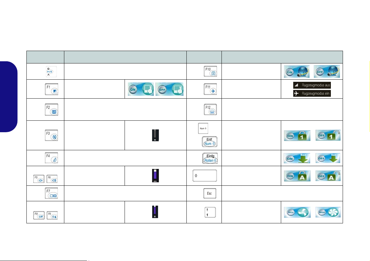
Funktionstasten
Wenn die Funktionstasten (F1 - F11) gleichzeitig mit der Fn-Taste gedrückt werden, funktionieren sie wie Hotkeys. Neben
den Tastenkombinationen für die Grundfunktionen gibt es einige visuelle Anzeigen (nur bei der Windows Desktop-An-
wendung, aber nicht im Start-Bildschirm), wenn der Hotkey Treiber ins talliert ist.
Tasten Funktion/ Visuelle Anzeigen Tasten Funktion/ Visuelle Anzeigen
Fn +
Fn +
Deutsch
Fn +
Fn +
Fn + Wechsel Schlaf/Wiederaufnahme
Fn +
Fn +
Fn +
Wiedergabe/Pause (in Audio /Videoprogrammen)
Touchpad aktivieren/
deaktivieren
LCD-Hintergrundlicht ausschalten (zum Ein-
schalten beliebige Taste drücken oder Touchpad
berühren)
Stummschaltung/
Stummschaltung
aufheben
Audio-Lautstärke
verringern/erhöhen
Ändern der Anzeigeeinstellungen (siehe Seite 44)
LCD-Helligkeit ver-
ringern/erhöhen
Tabelle 4 - Funktionstasten & visuelle Anzeigen
Fn +
Fn +
Fn +
/
Fn +
Fn +
Fn +
Fn +
PC-Kamera aktivieren/
deaktivieren
Flugzeugmodus ein-/
ausschalten
Tastaturbeleuchtung wechseln/Helligkeitsstufe
anpassen (Nur Beleuchtete Tastaturn)
Ein-/Ausschalten der
Nummerntastatur
Ein-/Ausschalten des
Scroll-Modus
Ein-/Ausschalten der
Feststelltaste
Ein-/Ausschalten des Control Center (Steuerzent-
rum) (siehe Seite 37)
Automatische Lüftersteuerung/Volle Leis-
tung
36

Control Center (Steuerzentrum)
Drücken Sie auf die Tastenkombination Fn + Esc, oder doppelklicken Sie auf das Symbol im Infobereich auf der Taskleiste um das Control Center (Steuerzentrum) ein-/auszuschalten in der Windows Desktop-Anwendung (nicht Start-Bild-
schirm). Das Control Center (Steuerzentrum) bietet den schnellen Zugriff auf häufig verwendete Funktionen, und Sie haben
hier die Möglichkeit, Module direkt ein-/auszuschalten.
Abb. 5 - Control Center
Klicken Sie auf eine beliebige Taste, um ein Modul (z. B. Touchpad, Kamera) ein-/auszuschalten. Klicken Sie auf Power
Conservation (Strom sparen), um einen der Modi Performance (Leistung), Balanced (Ausgeglichen) oder Energy Star
auszuwählen. Klicken Sie auf die Tasten (oder drücken Sie nur auf die Maustaste, und halten Sie diese gedrückt), um die
Helligkeit/Lautstärke (Brightness/Volume) einzustellen. Klicken Sie auf Display Switch (Anzeige wechseln)/Time Zone
(Zeitzone)/Desktop Background (Desktop-Hintergrund), um das entsprechende Windows-Systemsteuerungsfenster aufzurufen. Klicken Sie auf den Sleep (Schalter) für den Ruhezustand, um den Computer in den Ruhezustand oder in einen Ener-
giesparmodus zu versetzen.
Deutsch
37

Power Status (Energiestatus)
Das Energiestatus-Symbol zeigt an, ob die Stromversorgung aktuell über den Akku oder über das an das Stromnetz
angeschlossene Netzteil erfolgt. Die Energiestatus-Anzeige
zeigt den aktuellen Akkuladestatus an.
Sleep (Schalter)
Klicken Sie auf den Schalter für den Ruhezustand, um die
Schaltflächen Ruhezustand
fen. Klicken Sie dann auf eine der beiden Tasten, um den
Computer in den jeweiligen Modus zu versetzen.
oder Schlaf aufzuru-
Brightness (Helligkeits)
Das Helligkeits-Symbol zeigt die aktuell eingestellte Bildschirmhelligkeit an.Sie können die Bildschirmhelligkeit entweder mit dem Schieberegler oder mit der
Tastenkombination Fn + F8/F9 ändern. Mit der
Tastenkombination Fn + F2 wird das LED-Hintergrundlicht
ausgeschaltet (drücken Sie auf eine beliebige Taste, um es
wieder einzuschalten). Beachten Sie, dass die Bildschir-
Deutsch
mhelligkeit auch vom eingestellten Energiemodus abhängt.
Volume (Lautstärke)
Das Lautstärke-Symbol zeigt die aktuelle Lautstärke an.Sie
können die Lautstärke entweder mit dem Schieberegler oder
mit der Tastenkombination Fn + F5/F6 einstellen. Mit der
Tastenkombination Fn + F3 wird der Ton ausgeschaltet.
Power Conservation (Strom sparen)
Dieses System unterstützt die Energy Star-Stromsparfunktionen, die Computer (CPU, Festplatte usw.) nach einer
längeren Zeit der Inaktivität in einen Ruhemodus versetzen,
bei dem weniger Strom verbraucht wird. Klicken Sie entweder auf die Taste Performance, Balanced oder Energy
Star.
Display Switch (Anzeige wechseln)
Klicken Sie auf die Taste zum Wechseln des Anzeigegeräts,
um das Menü aufzurufen (Sie können dazu auch die
Tastenkombination + P verwenden), und wählen Sie
einen Anzeigemodus aus.
Time Zone (Zeitzone)
Wenn Sie auf die Schaltfläche Zeitzone klicken, wird das
Windows-Systemsteuerungsfenster Datum und Uhrzeit
aufgerufen.
Desktop Background (Desktop-Hintergrund)
Wenn Sie auf die Schaltfläche Desktop-Hintergrund klikken, können Sie das Bild für den Desktophintergrund einstellen.
Touchpad/PC-Kamera-Modul
Klicken Sie auf eine dieser Tasten, um das Touchpad oder
das Kamera-Modul ein- oder auszuschalten. Ist es ausgeschaltet, erscheint links oben am Symbol
Beachten Sie, dass der Energiestatus des Kamera-Moduls
auch vom ausgewählten Energiemodus abhängen.
ein Kreuz.
38

Systemübersicht: Ansicht von vorne, links, rechts, hinten und unten
Abb. 6 - Ansicht von vorne, links, rechts, hinten und
unten (Modelle A & B)
1. LED-Anzeigen
2. Multi-in-1 Kartenleser
3. DC-Eingangsbuchse
4. Luftungsoffnung
5. Schnittstelle für externen
Monitor
6. RJ-45 LAN-Buchse
7. Kombinierter eSATA/USB
3.0 Anschluss
8. HDMI-Ausgangsanschluss
9. USB 3.0 Anschlüsse
10. Mikrofon-Eingangsbuchse
11. Kopfhörer-Ausgangsbuchse
12. USB 2.0 Anschluss
13. Schacht für optisches
Laufwerk
14. Notauswurfloch
15. SicherheitsschloßBuchse
16. Akku
17. Komponentenfachabdekkung
18. Lautsprecher
Überhitzung
Zum Schutz vor Überhitzung Ihres Computers
dürfen die Luftungsoffnung(en) nicht während
das Notebook in Betrieb ist verdeckt werden.
Disc-Notauswurf
Wenn eine Disc manuell entnommen werden
muß (z.B. wegen eines Stromausfalls) können
Sie mit dem Ende einer geradegebogenen Büroklammer in das Notauswurfloch drükken.
Verwenden Sie hierzu aber keinen spitzen
Bleistift oder ähnliche Objekte, die im Loch
abbrechen und darin stekkenbleiben könnten.
USB 3.0
Die Datenübertragung ist bei
USB 3.0 viel
schneller als bei
USB 2.0, und
USB 3.0 ist
rückwärts
kompatibel mit
USB 2.0.
1
14
16
2
8
4
6
3
5
10
12
9
7
13
15
17
18
18
2
16
Vorderseite
Linke Seite
Hinterseite
Rechte Seite
Unterseite
9
11
4
4
(Modelle A & B)
Deutsch
39

Systemübersicht: Ansicht von vorne, links, rechts, hinten und unten
Abb. 7 - Ansicht von vorne, links, rechts, hinten und
unten (Modelle C & D)
1. LED-Anzeigen
2. Multi-in-1 Kartenleser
3. DC-Eingangsbuchse
4. Luftungsoffnung
5. Schnittstelle für externen
Monitor
6. RJ-45 LAN-Buchse
7. Kombinierter eSATA/USB
3.0 Anschluss
8. HDMI-Ausgangsanschluss
9. USB 3.0 Anschlüsse
10. Mikrofon-Eingangsbuchse
11. Kopfhörer-Ausgangsbuchse
12. USB 2.0 Anschluss
13. Schacht für optisches
Laufwerk
14. Notauswurfloch
15. SicherheitsschloßBuchse
16. Akku
17. Komponentenfachabdekkung
18. Lautsprecher
Überhitzung
Zum Schutz vor Überhitzung Ihres Computers
dürfen die Luftungsoffnung(en) nicht während
das Notebook in Betrieb ist verdeckt werden.
Disc-Notauswurf
Wenn eine Disc manuell entnommen werden
muß (z.B. wegen eines Stromausfalls) können
Sie mit dem Ende einer geradegebogenen Büroklammer in das Notauswurfloch drükken.
Verwenden Sie hierzu aber keinen spitzen
Bleistift oder ähnliche Objekte, die im Loch
abbrechen und darin stekkenbleiben könnten.
USB 3.0
Die Datenübertragung ist bei
USB 3.0 viel
schneller als bei
USB 2.0, und
USB 3.0 ist
rückwärts
kompatibel mit
USB 2.0.
1
14
16
2
8
4
6
3
5
10
12
9
7
13
15
17
4
18
18
16
11
9
4
4
4
Vorderseite
Linke Seite
Hinterseite
Rechte Seite
(Modelle C & D)
Deutsch
40

Windows 8.1 Systemsteuerung
Abb. 8
Kontextmenü
Verschieben Sie die Maus in
die linke untere Ecke des Bildschirms, und klikken Sie mit der
rechten Maustaste auf die
Start-Taste darauf, um das
Menü aufzurufen.
Abb. 9 - Start-Bildschirm
In diesem Handbuch finden Sie eine Anleitung zum Öffnen der Systemsteuerung. Klicken Sie mit der rechten Maustaste
auf die Start-Taste in der Desktop-App oder auf dem Start-Bildschirm (oder verwenden Sie die Tastenkombination
Windows-Logo-Taste + X), um ein erweitertes Kontextmenü der nützlichen Funktionen aufzurufen: Systemsteuerung,
Programme und Funktionen, Energieoptionen, Task-Manager, Suche, Datei-Explorer, Eingabeaufforderung, GeräteManager, Netzwerkverbindungen usw. Wählen Sie dann Systemsteuerung.
Windows 8.1 Start-Bildschirm und Desktop
Die Apps, Bedienfenster, Dienstprogramme und andere Software erreichen Sie bei Windows über den Start-Bildschirm und/oder die
Windows Desktop-App. Der Desktop (der im Start-Bildschirm eine
App startet) wird geöffnet durch Anklicken des Desktop-Eintrags im
Start-Bildschirm (oder durch Drükken der Tastenkombination
Windows-Logo-Taste + D). Die Taskleiste wird am unteren
Rand des Desktop-Bildschirms angezeigt. Der Infobereich befindet
sich in der rechten unteren Ecke des Bildschirms. Klicken Sie auf den
Pfeil unten auf dem Start-Bildschirm, um auf die Apps zuzugreifen.
41
Deutsch

Apps und Kacheln
Klicken Sie auf den Pfeil unten auf dem
Start-Bildschirm, um auf die Apps zuzugreifen.
Der Start-Bildschirm enthält bereits eine Reihe von Apps, die mit
jeder weiteren Installation erweitert wird. Wenn auf dem Bildschirm nicht ausreichend Platz ist, um alle Apps anzuzeigen, können Sie den Schieberegler am unteren Rand des Bildschirms
verwenden, um das Fenster entsprechend zu verschieben und die
gewünschten Apps sehen zu können.
Charms-Leiste
An der rechten Seite des Bildschirms wird die Charms-Leiste angezeigt. Die Charms-Leiste enthält die Menüs Suchen,
Teilen, Start, Geräte und Einstellungen. Um eines der Menüs aus der Charms-Leiste aufzurufen, bewegen Sie den Cursor
in die unteren rechten Ecken des Bildschirms und dann über den jeweiligen Eintrag in der Charms-Leiste, um diesen zu ak-
Deutsch
tivieren (ein aktivierter Eintrag wird schwarz dargestellt) oder drücken Sie auf die Tastenkombination Windows-Logo-Taste
+ C.
42
Abb. 10 - Start-Bildschirm mit Charms-Leiste

Grafikfunktionen
Dieses System verfügt sowohl über eine integrierte GPU
von Intel (zum Energie sparen) und eine diskrete GPU von
NVIDIA (für die Leistung). Wenn die Videotreiber in-
stalliert sind, können Sie die Anzeigegeräte wechseln und die
Anzeigeoptionen konfigurieren.
Microsoft Hybrid Graphics
Microsoft Hybrid Graphics ist eine nahtlose Technologie,
mit der bei längerer Akkubetriebsdauer die höchstmögliche
Leistung des Grafiksystems erreicht wird, ohne manuell die
Einstellungen ändern zu müssen. Der Computer wechselt automatisch übergangslos zwischen der integrierten UMA
(Unified Memory Architecture) GPU (iGPU) und der diskreten GPU (dGPU), wenn dieses von der verwendeten Anwendung erfordert wird.
So öffnen Sie in Windows das Einstellfenster Anzeige:
1. Rufen Sie die Systemsteuerung auf.
2. Klicken Sie auf Anzeige (Symbol) - im Kategorie Darstellung
und Anpassung.
3. Klicken Sie auf Bildschirmauflösung anpassen/Auflösung
anpassen.
Oder
4. Klicken Sie mit der rechten Maustaste auf den Desktop (der
Desktop wird aufgerufen, indem Sie die Windows Logo-Taste
und gleichzeitig auf D drücken) und dann die Option
Bildschirmauflösung wählen.
5. Wählen Sie aus dem Drop-down-Menü die Bildschirmauflösung .
6. Klicken Sie auf Erweiterte Einstellungen.
So rufen Sie die Steuerung für Intel® HD-Grafik auf:
1. Klicken Sie auf das Symbol (Steuerung für Intel® HD-Grafik)
auf dem Apps-Bildschirm.
Oder
2. Klicken Sie mit der rechten Maustaste auf den Desktop (der
Desktop wird aufgerufen, indem Sie die Windows Logo-Taste
und gleichzeitig auf D drücken) und dann aus dem Menü die
Option Grafikeigenschaften wählen.
Oder
3. Klicken Sie auf das Symbol im Infobereich auf der DesktopTaskleiste und dann aus dem Menü die Option
Grafikeigenschaften wählen.
So öffnen Sie die NVIDIA Systemsteuerung :
1. Rufen Sie die Systemsteuerung auf.
2.
Klicken Sie auf NVIDIA Systemsteuerung (Symbol) - im
Kategorie Darstellung und Anpassung.
Oder
3. Klicken Sie mit der rechten Maustaste auf den Desktop (der
Desktop wird aufgerufen, indem Sie die Windows Logo-Taste
und gleichzeitig auf D drücken) und dann aus dem Menü die
Option NVIDIA Systemsteuerung wählen.
Deutsch
43

Anzeigegeräte
Bildschirmauflösung für Apps (Windows 8.1)
Die Mindestauflösung für Apps ist 1024x768.
Damit alle Funktionen von Windows 8.1 unterstützt werden
(einschließlich Multitasking mit Snap), ist eine Mindestauflösung von 1366x768 erforderlich.
Abb. 11
+ P (Ändern der
Anzeigeeinstellungen)
Neben dem integrierten LCD-Monitor können Sie auch
einen externen VGA-Monitor/Flachbildschirm oder ein
Fernsehgerät (an die Schnittstelle für externen Monitor oder
an den HDMI-Ausgangsanschluss angeschlossen) als Anzeigegerät anschließen.
Deutsch
Wechseln der Anzeigegeräte mit der Windows-Logo-Taste und der Taste P
Wenn Sie gleichzeitig auf die Tasten und P (oder Fn +
F7) drücken, konnen Sie bei Windows schnell und einfach
die Anzeigeeinstellungen und -modi wechseln (was besonders praktisch ist, wenn Sie einen Projektor anschließen).
1. Schließen Sie das externe Anzeigegerät an die Schnittstelle für
externen Monitor oder an den HDMI-Ausgangsanschlussan an,
und schalten Sie es ein.
2. Drücken Sie die Tastenkombination + P (oder Fn + F7).
3. Auf dem Bildschirm erscheint ein Menü.
4. Wählen Sie mit den Cursor-T asten (oder + P) eine geeignete
Konfiguration aus dem Menü aus, und bestätigen Sie die
Auswahl durch Drücken der Eingabetaste.
44
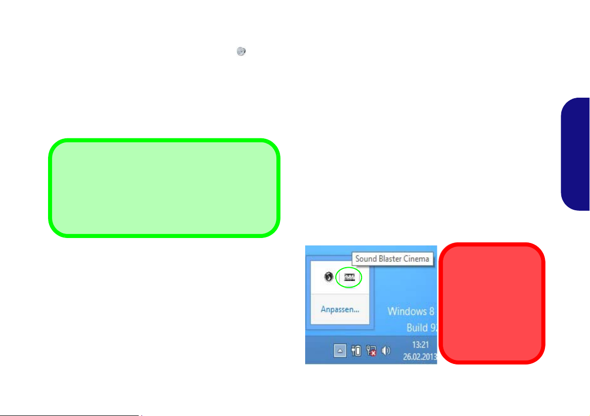
Audiofunktionen
Lautstärkeeinstellung
Die Lautstärke kann auch mit den Lautstärkeeinstellung im
Menü Einstellungen in der Charms-Bar (auf dem StartBildschirm) oder über das Lautsprecher-Symbol in der
Desktop-Taskleiste eingestellt werden.
Sound Blaster Cinema
& HDMI
Die Sound Blaster
Cinema-Audioeffekte
können nicht verwendet
werden, wenn der Klang
über einen HDMI-Anschluss erzeugt wird.
Sie können die Audio-Einstellungen Ihres Computers über
die Windows-Systemeinstellungen bei Sound , über das
HD VDeck-Symbol auf dem Desktop oder über das VIA HD
Audio Deck-Bedienfenster konfigurieren.
Sound Blaster Cinema EQ
Mit der Anwendung Sound Blaster Cinema können Sie die
Audioeinstellungen nach Ihren Anforderungen konfigurieren, um eine bestmögliche Audioleistung bei Spielen und der
Wiedergabe von Musik und Videos zu erreichen.
Die Lautstärke können Sie durch die Tastenkombination Fn
+ F5/F6 oder über das Lautsprecher-Symbol in der
Taskleiste ändern.
Creative Software AutoUpdate
Starten Sie die Anwendung über das Shortcut auf dem Apps-
Bildschirm. Stellen Sie eine Verbindung zum Internet her,
klikken Sie auf Weiter, und folgen Sie den Anweisungen auf
dem Bildschirm, um die Software zu aktualisieren.
Anwendung Sound Blaster Cinema
Starten Sie das Sound Blaster Cinema-Bedienfenster aus
dem Infobereich der Taskleiste heraus (oder über das entsprechende Symbol auf dem Apps-Bildschirm). Klicken Sie
auf die Registerkarten, um in die entsprechenden Menüs des
Bedienfensters zu gelangen.
Abb. 12 - Sound Blaster Cinema
(Symbol im Infobereich der Taskleiste)
45
Deutsch

Energieoptionen
Abb. 13 - Energieoptionen
Die Energieoptionen von Windows ermöglichen Ihnen die Konfiguration der Optionen für das Energiemanagement des Computers. Sie können Strom sparen, indem Sie Energiesparpläne erstellen und im linken Menü können Sie die Optionen für
den Netzschalter, die Energiespartasten (Fn + F4) und Zuklappeinstellung (beim Schließen des Dekkels) und den An-
zeige- und Energiesparmodus (die Standardeinstellung Energie sparen) konfigurieren. Beachten Sie, dass sich die Ener-
giesparpläne (Energiesparmodus) auf die Computerleistung auswirken.
Wählen Sie einen bestehenden Plan aus, oder klicken Sie im linken Menü auf Energiesparplan erstellen, und wählen Sie
die Optionen, um einen neuen Plan zu erstellen. Klicken Sie auf Energieplaneinstell ungen ändern, und klicken Sie auf Er-
weiterte Energieeinstellungen ändern, um weitere Optionen für die Konfiguration aufzurufen.
Deutsch
46

Installation der Treiber
Allgemeine Hinweise zur
Treiberinstallation
Wenn Sie keine fortgeschrittenen Kenntnisse
haben, folgen Sie für jeden
Treiber den Anweisungen
auf dem Bildschirm (z. B.
Weiter > Weiter > Fertig
stellen). In vielen Fällen
ist es erforderlich, den
Computer nach der
Treiberinstallation neu zu
starten.
Alle Module (z. B. WLAN
oder Bluetooth) müssen
vor der Treiberinstallation
eingeschaltet werden.
Windows Update
Nachdem Sie alle Treiber
installiert haben, sollten
Sie die Funktion Windows
Update aktualisieren, um
immer die neuesten Sicherheits-Updates usw. zu
erhalten (die Updates enthalten die neuesten
Fehlerbehebungen von
Microsoft).
Treiberinstallation und Stromversorgung
Während die Treiber installiert werden, muss der
Computer über den AC/DC-Adapter mit Strom versorgt werden. Einige Treiber benötigen für den Installationsvorgang sehr viel Strom. Wenn der Akku
nicht mehr über genügend Strom verfügt, kann sich
das System während der Installation ausschalten,
was zu Systemfehlern führen kann (das ist kein Sicherheitsproblem, und der Akku ist innerhalb von
einer Minute wieder aufladbar).
Abb. 14 - Installation der Treiber
Die Disc Device Drivers & Utilities + User's Manual enthält die Treiber und Hilfspro-
gramme, die für das einwandfreie Funktionieren des Computers notwendig sind. Möglicherweise wurden diese bereits vorinstalliert. Ist das nicht der Fall, legen Sie die Disc ein, und
klicken Sie auf Install Drivers (Schaltfläche) oder Option Drivers (Schaltfläche), um das
Treibermenü Optional aufzurufen.
Reihenfolge. Markieren Sie die Treiber, die installiert werden soll en (notieren Si e zum späteren Nachlesen die Treiber, die Sie installiert haben). Hinweis: Muss ein Treiber neu installiert
werden, sollten Sie den alten Treiber zunächst deinstallieren.
Manuelle Treiber-Installation
Klicken Sie in der Anwendung Drivers Installer auf die Schaltfläche Browse CD/DVD und
navigieren Sie zu der ausführbaren Datei in dem Ordner für Ihren Treiber.
Wenn während des Installationsvorgangs das Fenster Neue Hardware gefunden erscheint,
klicken Sie auf Abbrechen, um das Fenster zu schließen. Befolgen Sie dann die Installationsanweisungen.
Installieren Sie die Treiber in der in Abb. 14 angegebenen
Deutsch
47

3G-Modul
1
Model A
Ausrichtung der USIM-Karte
Die lesbare Seite der USIM-Karte
(die Seite, auf der sich die
Goldkontakte befinden) muss wie
abgebildet nach oben zeigen.
Model A
1
1
(Optional nur für Modelle A & B)
Wenn Ihr Modell das optionale 3G-Modul enthält, folgen Sie den nachfolgenden Anweisungen, um die USIM-Karte zu installieren (Sie erhalten sie von Ihrem Dienstanbieter). Installieren Sie dann die Anwendung.
Einsetzen der USIM-Karte
1. Schalten Sie den Computer aus, drehen Sie es herum, und nehmen Sie den Akku heraus (schieben Sie die Riegel in die unten
angezeigte Richtung, und ziehen Sie den Akku heraus).
2. Schieben Sie die USIM-Karte wie unten abgebildet hinein, und lassen Sie sie einrasten. Setzen Sie den Akku wieder ein.
Deutsch
Abb. 15 - Herausnehmen des Akkus und einsetzen der USIM-Karte
48

Fehlerbehebung
Problem Mögliche Ursache - Lösung
Die Module Wireless-LAN/
Bluetooth können nicht erkannt
werden.
Das PC-Kamera-Modul kann nicht
erkannt werden.
Die mit der PC-Kamera
aufgenommenen Dateien benötigen
zu viel Speicherplatz.
Im Flugzeugmodus sind die Module ausgeschaltet. Prüfen Sie der LED-Anzeige und/
oder Funktionstastenanzeige, ob der Computer im Flugzeugmodus ist (siehe Tabelle 2 auf
Seite 34). Mit der Tastenkombination Fn + F11 können Sie den Flugzeugmodus ein- oder
ausschalten (siehe Tabelle 4 auf Seite 36).
Das ist ausgeschaltet. Mit der Tastenkombination Fn + F10 können Sie das PC-Kamera-
Modul einschalten (siehe Tabelle 4 auf Seite 36). Starten Sie die Kamera-Anwend ung, um
das Kamerabild zu sehen.
Videodateien, die mit hoher Auflösung aufgenommen werden, erfordern sehr viel
Speicherplatz.
Beachten Sie, dass das Betriebssystem Windows mindestens 20GB (64bit) freien Speicher
im Laufwerk C: der Systempartition benötigt. Es wird empfohlen, die aufgenommenen
Videodateien in einem anderen Laufwerk als C: zu speichern, die Dateigröße der
Aufnahmedateien zu beschränken oder die Auflösung der Videos zu verringern.
Deutsch
49

Technische Daten
Aktualität der technischen Daten
Die in diesem Teil aufgeführten technischen Daten sind zum Zeitpunkt der
Druckstellung richtig. Bestimmte
Elemente (insbesondere Prozessortypen/-geschwindigkeiten) können im
Rahmen des Entwicklungsplans des
Herstellers zwischenzeitlich geändert
oder aktualisiert werden. Detailinformationen erhalten Sie bei Ihrem Servicezentrum.
Deutsch
Prozessor-Optionen
Modelle A & C:
Intel® Core™ i7 Prozessor
i7-4900MQ (2,80GHz)
8MB L3 Cache, 22nm, DDR3L-1600MHz,
TDP 47W
i7-4800MQ (2,70GHz), i7-4700MQ
(2,40GHz)
6MB L3 Cache, 22nm, DDR3L-1600MHz,
TDP 47W
i7-4600M (2,9GHz)
4MB L3 Cache, 22nm, DDR3L-1600MHz,
TDP 37W
Intel® Core™ i5 Prozessor
i5-4330M (2,80GHz), i5-4300M (2,60GHz),
i5-4200M (2,50GHz)
50
3MB L3 Cache, 22nm, DDR3L-1600MHz,
TDP 37W
Intel® Core™ i3 Prozessor
i3-4100M (2,50GHz), i3-4000M (2,40GHz)
3MB L3 Cache, 22nm, DDR3L-1600MHz,
TDP 37W
Intel®
Pentium® Processor
3550M (2,30GHz)
2MB L3 Cache, 22nm, DDR3L-1600MHz,
TDP 37W
Modelle B & D:
Intel® Core™ i7 Prozessor
i7-4900MQ (2,80GHz)
8MB L3 Cache, 22nm, DDR3L-1600MHz,
TDP 47W
i7-4800MQ (2,70GHz), i7-4700MQ
(2,40GHz)
6MB L3 Cache, 22nm, DDR3L-1600MHz,
TDP 47W
i7-4600M (2,9GHz)
4MB L3 Cache, 22nm, DDR3L-1600MHz,
TDP 37W
Intel® Core™ i5 Prozessor
i5-4330M (2,80GHz), i5-4300M (2,60GHz),
i5-4200M (2,50GHz)
3MB L3 Cache, 22nm, DDR3L-1600MHz,
TDP 37W
Intel® Core™ i3 Prozessor
i3-4100M (2,50GHz), i3-4000M (2,40GHz)
3MB L3 Cache, 22nm, DDR3L-1600MHz,
TDP 37W
Core Logic
Intel® HM86 Chipsatz
BIOS
AMI BIOS (48Mb SPI Flash-ROM)
Speicher
Zwei 204-Pin SODIMM-Sockel,
Unterstützung von DDR3L 1600MHz
Speicher
Speicher auf bis zu 16GB erweiterbar
(Die tatsächliche Speicherarbeitsfrequenz
hängt vom FSB des Prozessors ab.)
Speicher
(Werkseitige Option) Ein austauschbares
optisches Laufwerk (12,7mm Höhe) (Super
Multi-Laufwerk/kombinierte Blu-RayLaufwerk/Blu-Ray-Writer-Laufwerk)
(Werkseitige Option) 2,5” 9,5mm zweiter
HDD-Caddy
Eine austauschbare SATA-2,5"-Festplatte
(9,5mm/7,0mm Höhe)
(Werkseitige Option) Ein mSATA-SSDLaufwerk
LCD
Modelle A & B:
15,6" (39,62cm) HD / FHD
Modelle C & D:
17,3" (43,94cm) HD+ / FHD

Videoadapter
Integrierte GPU von Intel® und Diskrete
GPU von NVIDIA®
Unterstützt Microsoft Hybrid Graphics
Modelle A & C:
Integrierte GPU von Intel® (die GPU ist
vom Prozessor abhängig)
Intel® HD Graphics 4600/Intel® HD
Graphics
Dynamische Frequenz (Intel Dynamic Video
Memory Technology für bis zu 1,7GB)
Kompatibel mit MS DirectX® 11
Diskrete GPU von NVIDIA®
NVIDIA® GeForce 840M
2GB GDDR3 Video-RAM On Board
Kompatibel mit MS DirectX® 11.1
Modelle B & D:
Integrierte GPU von Intel® (die GPU ist
vom Prozessor abhängig)
Intel® HD Graphics 4600/Intel® HD
Graphics
Dynamische Frequenz (Intel Dynamic Video
Memory Technology für bis zu 1,7GB)
Kompatibel mit MS DirectX® 11
Diskrete GPU von NVIDIA®
NVIDIA® GeForce GTX 850M
2GB GDDR3 Video-RAM On Board
Kompatibel mit MS DirectX® 11.1
Audio
High-Definition-Audio-kompatible
Schnittstelle
2 eingebaute Lautsprecher
Eingebautes Mikrofon
Sound Blaster
™
Cinema
Sicherheit
Öffnung für Sicherheitsschloß (Typ
Kensington)
BIOS-Paßwort
Tastatur
Modelle A & B:
"Win Key"-T astatur (mit Nummerntastatur) in
Normalgröße
Modelle C & D:
"Win Key"-T astatur (mit Nummerntastatur) in
Normalgröße
(Werkseitige Option) Beleuchtete "Win
Key"-Tastatur (mit Nummerntastatur) in
Normalgröße
Zeigegerät
Eingebautes Touchpad
Schnittstellen
Ein USB 2.0-Anschluss
Zwei USB 3.0-Anschlüsse
Ein eSATA-Anschluss (kombinierter USB
3.0-Anschluss)
Ein HDMI-Ausgangsanschluss
Eine Schnittstelle für externen Monitor
Eine Lautsprecher/Kopfhörer-
Ausgangsbuchse
Eine Mikrofon-Eingangsbuchse
Eine RJ-45 LAN-Buchse
Eine DC-Eingangsbuchse
Mini-Card-Steckplätze
Modelle A & B:
Steckplatz 1 für Wireless-LAN-Modul oder
Kombinierte Bluetooth und WLAN-Modul
(Werkseitige Option) Steckplatz 2 für 3GModul oder mSATA-SSD-Laufwerk
Modelle C & D:
Steckplatz 1 für Wireless-LAN-Modul oder
Kombinierte Bluetooth und WLAN-Modul
(Werkseitige Option) Steckplatz 2 für
mSATA-SSD-Laufwerk
Kartenleser
Festes Multi-in-1 Kartenleser-Modul
MMC (MultiMedia Card) / RS MMC
SD (Secure Digital) / Mini SD / SDHC/
SDXC
MS (Memory Stick) / MS Pro / MS Duo
Deutsch
51

Kommunikation
Gbit Ethernet-LAN eingebaut
1,0M HD PC-Kamera-Modul
(Werkseitige Option) 2,0M FHD PC-
Kamera-Modul
(Werkseitige Option - Nur Modelle A & B)
3G Mini-Card-Modul
WLAN/ Bluetooth Half Mini-Card Module:
(Werkseitige Option) Intel® Wireless-AC
7260 WLAN (802.11a/c) und Bluetooth 4.0
(Werkseitige Option) Intel® Wireless-N
7260 WLAN (802.11a/g/n) und Bluetooth
4.0
Deutsch
(Werkseitige Option) Intel® Wireless-N
7260 WLAN (802.11b/g/n) und Bluetooth
4.0
(Werkseitige Option) Wireless LAN
(802.11b/g/n) (andere Hersteller)
(Werkseitige Option) Wireless LAN
(802.11b/g/n) und Bluetooth 4.0 (andere
Hersteller
Umgebungsbedingungen
Temperatur
In Betrieb: 5ºC – 35ºC
Bei Aufbewahrung: -20ºC – 60ºC
Relative Luftfeuchtigkeit
In Betrieb: 20 – 80 %
Bei Aufbewahrung: 10 – 90 %
Stromversorgung
Modelle A & C:
AC/DC-Adapter für den gesamten
Spannungsbereich
AC-Eingang: 100-240 V, 50-60Hz
DC-Ausgang: 19V, 4,74A (90W)
(Werkseitige Option) Smart Lithium-IonenAkkupack mit 6 Zellen, 62,16WH
(Werkseitige Option) Smart Lithium-IonenAkkupack mit 6 Zellen, 48,84WH
Modelle B & D:
AC/DC-Adapter für den gesamten
Spannungsbereich
AC-Eingang: 100-240 V, 50-60Hz
DC-Ausgang: 19,5V, 6,15A (120W)
(Werkseitige Option) Smart Lithium-IonenAkkupack mit 6 Zellen, 62,16WH
(Werkseitige Option) Smart Lithium-IonenAkkupack mit 6 Zellen, 48,84WH
Abmessungen und Gewicht
Modelle A & B:
374 (B) x 252 (T) x 14 - 31,4 (H) mm
Oder
374 (B) x 249,5 (T) x 14,8 - 32,8 (H) mm
2,5kg (mit optischem Laufwerk und
62,16WH-Akku)
Modelle C & D:
413 (B) x 272,8 (T) x 36,4 (H) mm
3,1kg (mit optischem Laufwerk und
62,16WH-Akku)
52

A propos de ce Guide Utilisateur Concis
Ce guide rapide est une brève introduction à la mise en route de votre système. Il s’agit d’un supplément, et non pas d’une
alternative au Manuel de l’Utilisateur en Anglais complet au format Adobe Acrobat s ur le disque Device Drivers & Utilities
+ User's Manual fourni avec votre ordinateur . Ce disque contient aussi les pilo tes et utilitaires nécessaires au fonctionnement
correct de votre ordinateur (Remarque: La compagni e se réserve le droit de revoir cette publication ou de modifier son contenu sans préavis).
Certains ou tous les éléments de l’ordinateur peuvent avoir été déjà installés. Si ce n’est pas le cas , ou si vous avez l’intention
de reconfigurer (ou réinstaller) des portions du système, reportez-vous au Manuel de l’Utilisateur complet. Le disq ue Device
Drivers & Utilities + User’s Manual ne contient pas de système d’exploitation.
Informations de réglementation et de sécurité
Prêtez attention aux avis réglementaires et informations de sécurité contenus dans le Manuel de l'Utilisateur se trouvant sur
le disque Device Drivers & Utilities + User’s Manual.
© Janvier 2014
Marques déposées
Intel, Intel Core et Pentium sont des marques déposées ou enregistrées d’Intel Corporation.
Français
53

Instructions d’entretien et d’utilisation
L’ordinateur est robuste, mais il peut toutefois être endommagé. Afin d’éviter ceci, veuillez suivre ces recommandations :
• Ne le laissez pastomber. Ne l’exposez à aucun choc ou vibration.
Si l’ordinateur tombe, le boîtier et d’autres éléments pourraient être
endommagés.
• Gardez-le sec. Ne le laisser pas surchauffer. Tenez l’ordinateur et
son alimentation externe à distance de toute source de chaleur. Il
s’agit d’un appareil électrique. Si de l’eau ou tout autre liquide venait
à pénétrer à l’intérieur de votre ordinateur, il pourrait être sérieusement endommagé.
• Evitez les interférences. Tenez l’ordinateur à distance de transfor-
mateurs à haute capacité, moteurs électriques, et autres appareils
générateurs de champs magnétiques importants. Ceux-ci peuvent
gêner ses performances normales et endommager vos données.
• Suivez les procédures appropriées d’utilisation de votre ordina-
teur. Arrêtez l’ordinateur correctement, et fermez tous vos programmes (n’oubliez pas d’enregistrer votre travail). N’oubliez pas
d’enregistrer vos données régulièrement puisqu’elles peuvent être
Français
perdues si la batterie est vide.
Révision
Si vous essayez de réparer l'ordinateur par vous-même, votre
garantie sera annulée et vous risquez de vous exposer et d'exposer l'ordinateur à des chocs électriques. Confiez toute réparation à un technicien qualifié, particulièrement dans les cas
suivants:
• Si le cordon d’alimentation ou l’adaptateur AC/DC est endommagé,
abimé ou effiloché.
• Si votre ordinateur a été exposé à la pluie ou tout autre liquide.
• Si votre ordinateur ne fonctionne pas normalement bien que vous
ayez suivi les instructions de mise en marche à la lettre.
• Si votre ordinateur est tombé par terre ou a été endommagé (si l'écran
LCD est cassé, ne touchez pas le liquide car il contient du poison).
• Si une odeur inhabituel, de la ch ale ur ou de la fu mée ap par ais sait so rtant de votre ordinateur.
Informations de sécurité
• Utilisez uniquement un adaptateur AC/DC agréé avec votre ordinateur.
• Utilisez uniquement le cordon d’alimentation et les batteries indiqués
dans ce manuel. Ne jetez pas les batteries dans le feu. Elles peuvent
exploser. Consultez la réglementation locale pour des instructions de
recyclage possibles.
• Ne continuez pas d'utiliser une batterie qui est tombée, ou qui paraît
endommagée (ex: tordue ou vrillée) d'une manière quelconque.
Même si l'ordinateur continue de fonctionner avec la batterie en
place, cela peut détériorer le circuit, pouvant déclencher un incendie.
• Assurez-vous que votre ordinateur est complètement éteint avant de
le mettre dans un sac de voyage (ou tout autre bagage similaire).
• Avant de nettoyer l'ordinateur, retirez la batterie et assurez-vous que
l'ordinateur est débranché de toute alimentation électr iq ue externe,
périphériques et câbles (y compris les lignes téléphoniques).
• Utilisez un chiffon propre et doux pour nettoyer l'ordinateur, mais
n'appliquez pas d'agent de nettoyage directement sur l'ordinateur.
N’utilisez pas de produit de nettoyage volatil (des distillés pétrôle) ou
abrasifs sur aucun des éléments de l’ordinateur.
• N’essayez jamais de réparer la batterie. Au cas où votre batterie
aurait besoin d’être réparée ou changée, veuillez vous adresser à
votre représentant de service ou à des professionnels qualifiés.
• Notez que dans les ordinateurs ayant un logo fixé par dépôt électrolytique, le logo est recouvert par une protection adhésive. À cause de
l’usure générale, cette protection adhésive se détériore avec le temps
et le logo exposé peut former des angles coupants. Faites bien attention lorsque vous manipulez l'ordinateur, et évitez de toucher le logo
fixé par dépôt électrolytique. Dans la sacoche de voyage, ne mettez
pas d’autres objets qui risquent de se frotter contre l’ordinateur pendant le transport. En cas d’une telle usure, contactez votre centre de
services.
54

Précautions concernant les batteries polymères
Elimination de la batterie & avertissement
Le produit que vous venez d’acheter contient une batterie rechargeable. Cette batterie est recyclable. Quand elle n’est plus
utilisable, en fonction des lois locales des différents états et
pays, il peut être illégal de s’en débarrasser en la jetant avec les
ordures ménagères normales. Vérifiez auprès du responsable
local de l’élimination des déchets solides de votre quartier pour
vous informer des possibilités de recyclage ou de la manière appropriée de la détruire.
Il existe un danger d’explosion si la batterie est remise de façon
incorrecte. Remplacez-la uniquement par des batteries de
même type ou de type équivalent, recommandées par le fabricant. Eliminez les batteries usagées selon les instructions du fabricant.
Notez les informations suivantes spécifiques aux batteries polymères, et le cas échéant, celles-ci remplacent les informations générales de précaution sur les batteries.
• Les batteries polymères peuvent présenter une légère dilatation ou
gonflement, mais cela est inhérent au mécanisme de sécurité de la
batterie et ne représente pas une anomalie.
• Manipulez les batteries polymères de façon appropriée lors de leur
utilisation. Ne pas utiliser de batteries polymères dans des environnements présentant une température ambiante élevée, et ne pas stocker
les batteries non utilisées pendant de longues périodes.
Français
55

Guide de démarrage rapide
Arrêt
Veuillez noter que vous devriez toujours
éteindre votre ordinateur en utilisant la commande Arrêter dans Windows (voir ci-dessous). Cette précaution évite des problèmes de
disque dur ou de système.
Cliquez sur Périphériques dans la barre des
charmes (utilisez la combinaison de touches
Touche Logo de Windows + touche C
pour accéder à la barre des charmes) et sélectionnez Arrêter dans el menu Marche/Arrêt.
Ou
Sélectionnez Arrêter ou se déconnecter >
Arrêter dans el menu contextuel (utilisez la
combinaison de touches Touche Logo de Windows + touche X pour accéder au menu
contextuel).
130°
Figure 1 - Ouvrir le couvercle/LCD/ordinateur avec un adaptateur AC/
DC branché
1. Enlevez tous les memballages.
2. Posez l’ordinateur sur une surface stable.
3. Installez la batterie et assurez-vous qu’elle correc-
tement positionnée.
4. Connectez fermement les périphériques que vous
souhaitez utiliser avec votre ordinateur (par ex.
clavier et souris) à leurs ports respectifs.
5. Branchez l'adaptateur AC/DC à la prise d'entrée
DC sur la gauche de l’ordinateur, branchez
ensuite le cordon secteur à une prise murale, puis
à l’adaptateur AC/DC.
6. D'une main, soulevez soigneusement le cou-
vercle/LCD pour obtenir un angle de vision confortable (ne pas dépasser 130 degrés), de l'autre
main (comme illustré dans la Figure 1) maintenez
la base de l'ordinateur (Remarque : Ne soulevez
jamais l'ordinateur par le couvercle/LCD).
7. Pressez le bouton de mise en marche pour allu-
Français
mer.
Logiciel système
Votre ordinateur peut être livré avec un logiciel
système pré-installé. Si ce n’est pas le cas, ou si
vous re-configurez votre ordinateur pour un
système différent, vous constaterez que ce manuel fait référence à Microsoft Windows 8.1.
56

Différences de modèles
Cette série d’ordinateurs portables inclut quatre types de modèles dont les dif férences sont indi quées dans le tableau ci-dessous. Remarquez que l’apparence de votre modèle peut être légèrement différente de celles présentées dans ce manuel.
Caractéristique Modèle A Modèle B Modèle C Modèle D
Adaptateur Vidéo
LCD
Module 3G
Mise en marche
GPU intégré Intel®
(Intel® HD Graphics
4600/Intel® HD Gra-
phics) et GPU discret
NVIDIA® (NVIDIA®
GeForce
Sortie DC: 19V, 4,74A
840M
)
15,6" (39,62cm) HD/FHD 17,3" (43,94cm) HD+/FHD
(90W)
GPU intégré Intel®
(Intel® HD Graphics
4600/Intel® HD Gra-
phics) et GPU discret
NVIDIA® (NVIDIA®
GeForce GTX
Option Non
Sortie DC: 19,5V, 6,15A
(120W)
850M
)
GPU intégré Intel®
(Intel® HD Graphics
4600/Intel® HD Gra-
phics) et GPU discret
NVIDIA® (NVIDIA®
GeForce
Sortie DC: 19V, 4,74A
(90W)
840M
)
Tableau 1 - Différences de modèles
GPU intégré Intel®
(Intel® HD Graphics
4600/Intel® HD Gra-
phics) et GPU discret
NVIDIA® (NVIDIA®
GeForce GTX
Sortie DC: 19,5V, 6,15A
(120W)
850M
)
Français
57

Carte du système: Vue de face avec l’écran LCD ouvert
Utilisation des appareils sans fil à
bord d'un avion
L'utilisation de tout appareil électronique de transmission est généralement interdite à bord d'un avion.
Vérifiez que les modules WLAN &
Bluetooth sont désactivés si vous
utilisez l'ordinateur à bord d'un avion en mettant le système en Mode
Avion.
Figure 2
Vue de face avec l’écran LCD ouvert
(Modèles A & B)
1. Caméra PC
2. Microphone
3. *Indicateur LED de caméra PC
*Quand la caméra PC est en cours
d'utilisation le Indicateur LED sera
illuminé en rouge.
4. Écran LCD
5. Bouton d'alimentation
6. Indicateurs LED
7. Clavier
8. Pavé tactile (Touchpad) et boutons
5
7
6
2
1
3
4
8
8
Remarquez que la zone d’utilisation
valide du Touchpad et des boutons
est celle indiquée à l’intérieur des
lignes en pointillé rouges.
(
Modèles A & B)
Français
58

Carte du système: Vue de face avec l’écran LCD ouvert
Utilisation des appareils sans
fil à bord d'un avion
L'utilisation de tout appareil
électronique de transmission est
généralement interdite à bord
d'un avion.
Vérifiez que les modules WLAN
& Bluetooth sont désactivés si
vous utilisez l'ordinateur à bord
d'un avion en mettant le système en Mode Avion.
Figure 3
Vue de face avec l’écran LCD ou-
vert (Modèles C & D)
1. Caméra PC
2. Microphone
3. *Indicateur LED de caméra PC
*Quand la caméra PC est en cours
d'utilisation le Indicateur LED sera
illuminé en rouge.
4. Écran LCD
5. Bouton d'alimentation
6. Indicateurs LED
7. Clavier
8. Clickpad/Touchpad
5
7
6
2
1
3
4
8
Sensibilité du
Clickpad/Touchpad
Les zones de bouton
de souris au bas du
pavé mesurent environ
15mm à partir du bas
du pavé, et les boutons
gauche et droit sont divisés à peu près au milieu comme illustré cidessous. Appuyez sur
la zone du bouton
gauche pour faire un
clic gauche, et sur la
zone du bouton droit
pour faire un clic droit.
8
(
Modèles C & D)
Français
59

Indicateurs LED
Les indicateurs LED sur votre ordinateur affichent des infor mations utiles sur l’état actuel de votre ordinateur.
Icône Couleur Description
Icône Couleur Description
Français
60
Orange L'adaptateur AC/DC est branché
Vert L’ordinateur est allumé
Vert
clignotant
Orange La batterie est en charge
Vert
Orange
clignotant
Vert
Vert
Tableau 2 - Indicateurs d’alimentation LED
Le système est dans le mode de
Veille configuré
La batterie est complètement char-
gée
La batterie a atteint le niveau bas
critique
Le disque dur/périphérique optique
est en cours d'utilisation
Mode Avion activé (les modules
WLAN, 3G & Bluetooth sont désacti-
vés)
Bleue
Bleue
Bleue
Tableau 3 - Indicateurs d’etat LED
Verrouillage numérique (pavé numé-
rique) activé
Verrouillage majuscule activé
Verrouillage défilement activé

Clavier
Numeric
Keypad
Numeric
Keypad
Touche Logo de Windows
Touche Menu/Application
Raccourci clavier du logo
de Windows
Utilisez la combinaison des
touches Touche Logo de
Windows + D pour
passer de l'écran d'accueil
au bureau de Windows.
Raccourci clavier de
Menu/Application
Lorsque l'application Bureau est activée, vous pouvez utiliser la touche
Menu/Application du
clavier pour effectuer un
clic droit de souris. Dans
l'écran d'accueil cette fonction est utile pour afficher
rapidement la barre Per-
sonnaliser.
Touches Fonction
Touche Fn
Pavé
numérique
Verr Num &
ArrêtDét
Touche Logo de Windows
Touche Menu/Application
Touches Fonction
Touche Fn
Pavé
numérique
Verr Num &
ArrêtDét
Modèles A & B
Modèles C & D
Le clavier est doté d'un pavé numérique intégré pour une sais ie des donn ées numériq ues plus facile. Le fait d'appuyer sur Fn
+ Verr Num (Modèles A & B)/Ve rr Num (Modèles C & D) active ou désactive le pavé numérique. Il est également doté
de touches fonction pour vous permettre de changer instantanément de mode opérationnel.
(Claviers lumineux seulement) Le niveau d'éclairage du clavier peut être réglé, ou allumé/éteint, à l'aide des touches Fn +
F12.
Figure 4 - Clavier
Français
61

Touches fonction
Les touches de fonctions (F1 - F11 etc.) agiront comme touches de raccourci (hot-key) quand pressée en maintenant la touche
Fn appuyée. En plus des combinaisons des touches de fonction de base, des indicateurs visuels sont disponibles (dans l'ap-
plication Bureau de Windows uniquement et pas dans l'écran d'accueil) quand le pilote de touches de raccourci (HotKey
Driver) est installé.
Touches Fonction/ indicateurs visuels Touches Fonction/ indicateurs visuels
Fn +
Fn +
Fn +
Fn +
Français
Fn +
Fn +
Fn +
Fn +
62
Lecture/Pause (dans les programmes audio/vidéo)
Activer/Désactiver le
Touchpad
Eteindre le rétroéclairage LCD (Appuyez sur une
touche ou utilisez le Touchpad pour allumer)
Allume/Éteind le son
Permutation veille
Diminution/Augmentation du
volume sonore
Modifiez la configuration de l'affichage (voir la
page 70)
Diminution/Augmentation de
la luminosité de l’écran LCD
Tableau 4 - Touches de fonctions & indicateurs visuels
Fn +
Fn +
Fn +
Fn +
Fn +
Fn +
Fn +
Activer/Désactiver le
module caméra PC
Permutation du mode
Avion
Allumer ou éteindre l’éclairage du clavier/Ajuster le
/
Activer/Désactiver le pavé
Activer/Désactiver l'arrêt
Basculer entre majuscule
et minuscule
Basculer entre les centres de contrôle (Control Cen-
Contrôle Automatique du
Ventilateur /Pleine Puis-
niveau de luminosité
(Claviers lumineux seulement)
numérique
défilement
ter) (voir la page 63)
sance

Control Center (Centre de contrôle)
Lorsque vous êtes dans l'application Bureau de Windows (pas dans l'écran d'accueil) appuyez sur la combinaison de touches
Fn + Échap ou double-cliquez sur l'icône dans la zone de notification de la barre des tâches pour activer/désactiver le
Control Center (Centre de contrôle).
quemment utilisées, et vous permet de rapidement d'activer/désactiver des modules.
Le Control Center (Centre de contrôle) donne un accès rapide aux commandes fré-
Figure 5 - Control Center
Français
Cliquez sur un bouton pour activer/désactiver l'un des modules (par exemple, Touchpad, Appareil photo). Cliquez sur Power
Conservation (Économie d'énergie) pour basculer entre les modes Performance (Performances), Balanced (Equilibré) ou
Energy Star. Cliquez sur les boutons (ou cliquez et maintenez simplement le bouton de la souris) pour ajuster le curseur de
Luminosité (Brightness)/Volume. Cliquez sur Display Switch (Permutation d’af fichage)/ Time Zone (Fuseau horaire)/Desktop Background (Fond d'écran du bureau) pour faire apparaître le panneau de configuration de W indows approprié. Cliquez
sur le bouton Veille pour mettre l'ordinateur en mode Veille prolongée ou Veille.
63

Power Status (État d'alimentation)
L'icône État d'alimentation indique si vous êtes actuellement alimenté par la batterie, ou par l'adaptateur AC/DC
branché à une prise de courant. La barre d’état d’alimentation indiquera l'état de charge actuel de la batterie.
Sleep (Veille)
Cliquez sur le bouton Veille pour faire apparaître les boutons
Veille Prolongée
boutons pour que l'ordinateur entre dans le mode d’économie
d'énergie appropr i é .
ou Veille , et cliquez sur l’un des
Brightness (Luminosité)
L'icône Luminosité indiquera le niveau de luminosité actuel
de l'écran. Vous pouvez utiliser le curseur pour ajuster la luminosité de l'écran ou les combinaisons de touches Fn + F8/
F9, ou utiliser la combinaison de touches Fn + F2 pour
éteindre le rétroéclairage LED (appuyez sur une touche pour
le rallumer). Notez que la luminosité de l'écran est également
affectée par le Mode d'alimentation choisi.
Volume
L'icône Volume indiquera le niveau du volume actuel. Vous
pouvez utiliser le curseur pour régler le volume ou les combinaisons de touches Fn + F5/F6, ou utiliser les combinai-
Français
sons de touches Fn + F3 pour couper le volume.
Power Conservation (Économie d'énergie)
Ce système prend en charge les fonctionnalités de gestion
d’alimentation Energy S tar qui placent les ordinateurs (CPU,
disque dur, etc.) dans des modes veille à faible consommation
d'énergie après une période d'inactivité donnée. Cliquez sur le
bouton Performance (Performances), Balanced (Equilibré)
ou Energy Star.
Display Switch (Permutation d’affichage)
Cliquez sur le bouton Permutation d’affichage pour accéder au menu (ou utilisez la combinaison de touches + P)
et sélectionnez le mode d'affichage joint approprié.
Time Zone (Fuseau horaire)
Cliquer sur le bouton Fuseau horaire permet d’accéder au
panneau de configuration de Date et heure de Windows.
Desktop Background (Fond d'écran du bureau)
Cliquer sur le bouton Fond d'écran du bureau vous permettra de changer l'image du fond d'écran du bureau.
Touchpad/caméra PC
Cliquez sur l’un de ces boutons pour permuter l’état d’alimentation du TouchPad ou du module caméra. Une icône
barrée apparaît au-dessus du coin supérieur gauche de l'icône
quand elle est désactivée. Notez que l'état de l'alimenta-
tion du module caméra est également affecté par le mode
d'alimentation choisi.
64

Carte du système: Vues de face, gauche, droite, arrière & dessous
Figure 6 - Vues de face, gauche, droite, arrière & des-
sous (Modèles A & B)
1. Indicateurs LED
2. Lecteur de carte multi-en-1
3. Prise d’entrée DC
4. Ventilation
5. Port moniteur externe
6. Prise réseau RJ-45
7. Port combiné eSATA et
USB 3.0
8. Prise de sortie HDMI
9. Ports USB 3.0
10. Prise d'entrée de
microphone
11. Prise de sortie hautparleurs/casque
12. Port USB 2.0
13. Baie de périphérique
optique
14. Trou d’ejection d’urgence
15. Fente de verrouillage de
sécurité
16. Batterie
17. Couvercle de baie de
composant
18. Haut-parleurs
1
14
16
2
8
4
6
3
5
10
12
9
7
13
15
17
1818
2
16
Face
Gauche
Arrière
Dessous
Droit
Surchauffe
Afin de ne pas causer une surchauffe de votre
ordinateur, verifiez que rien ne bouche la (les)
ventilation(s) quand le systeme est allumé.
Ejection d’urgence du disque
Si vous devez éjecter manuellement un
disque (par ex. suite à une coupure de courant) vous pouvez enfoncer l’extrémité d’un
trombone redressé dans le trou d’ejection
d’urgence. N’utilisez pas la pointe d’un
crayon, ou tout autre objet similaire qui pourrait se casser et rester coincé dans le trou.
Port USB 3.0
USB 3.0
transfèrera
des données
bien plus rapidement que
l’USB 2.0, et
il est compatible en
amont avec
USB 2.0.
9
11
4
4
(Modèles A & B)
Français
65

Carte du système: Vues de face, gauche, droite, arrière & dessous
Figure 7 - Vues de face, gauche, droite, arrière & dessous
(Modèles C & D)
1. Indicateurs LED
2. Lecteur de carte multi-en-1
3. Prise d’entrée DC
4. Ventilation
5. Port moniteur externe
6. Prise réseau RJ-45
7. Port combiné eSATA et USB
3.0
8. Prise de sortie HDMI
9. Ports USB 3.0
10. Prise d'entrée de microphone
11. Prise de sortie hautparleurs/casque
12. Port USB 2.0
13. Baie de pé riphérique
optique
14. Trou d’ejection d’urgence
15. Fente de verrouillage de
sécurité
16. Batterie
17. Couvercle de baie de
composant
18. Haut-parleurs
Dessous
Surchauffe
Afin de ne pas causer une surchauffe de votre
ordinateur, verifiez que rien ne bouche la (les)
ventilation(s) quand le systeme est allumé.
Ejection d’urgence du disque
Si vous devez éjecter manuellement un
disque (par ex. suite à une coupure de courant) vous pouvez enfoncer l’extrémité d’un
trombone redressé dans le trou d’ejection
d’urgence. N’utilisez pas la pointe d’un
crayon, ou tout autre objet similaire qui pourrait se casser et rester coincé dans le trou.
Port USB 3.0
USB 3.0
transfèrera
des données
bien plus rapidement que
l’USB 2.0, et il
est compatible en amont
avec USB 2.0.
1
14
2
8
4
6
3
5
10
12
9
7
13
15
16
11
9
16
17
18
18
4
4
4
Face
Gauche
Arrière
Droit
4
(Modèles C & D)
Français
66

Panneau de Configuration de Windows 8.1
Figure 8
Menu
contextuel
Déplacez la souris vers le
coin inférieur gauche de
l'écran et faites un clic
droit sur le bouton Démarrer pour accéder au
menu.
Figure 9 - Écran d'accueil
Tout au long de ce manuel, vous verrez une instruction pour ouvrir le Panneau de Configuration. Faites un clic droit sur
le bouton Démarrer dans l'appli Bureau ou sur l'écran d'accueil (ou utilisez la combinaison de touches Touche Logo de
Windows + X) pour faire apparaître un menu contextuel avancé de fonctionnalités utiles telles que Panneau de configu-
ration, Programmes et fonctionnalités, Options d'alimentation, Gestionnaire de tâches, Rechercher, Explorateur de fichiers,
Invite de commandes, Gestionnaire de périphériques et Connexions réseau, et plus encore et sélectionnez Panneau de Confi-
guration.
Écran d'accueil & bureau de Windows 8.1
Les applications, les panneaux de contrôle, les utilitaires et les programmes
dans Windows sont accessibles depuis l'écran d'accueil et/ou l'application
Bureau de Windows. Le Bureau (qui fonctionne comme une application
dans l'écran d'accueil) est accessible en cliquant sur l'élément Bureau dans
l'écran d'accueil (ou en utilisant la combinaison de touches Touche Logo de
Windows + D). La barre des tâches est affichée au bas de l'écran du bu-
reau, et vous pouvez voir la zone de notification de la barre des tâches en bas
à droite de l'écran. Cliquez sur la flèche en bas de l'écran d'accueil pour accéder à Applications.
Français
67

Applications et Vignettes
Cliquez sur la flèche en bas de
l'écran d'accueil pour accéder à Applications.
L'écran d'accueil contiendra un certain nombre d'applications, et bien
d'autres seront installées lorsque vous ajouterez des applications, etc.
T outes ces applications peuvent tenir sur un seul écran ainsi vous aurez
souvent besoin d'utiliser le curseur au bas de l'écran afin d'afficher
toutes les applications nécessaires.
Barre des charmes
Le côté droit de l'écran affiche la Barre des charmes. La Barre des charmes contient les menus Rechercher, Partager, Accueil, Périphériques et Paramètres. Pour accéder à la Barre des charmes déplacez le curseur vers les coins supérieurs ou
inférieurs à droite de l'écran, puis passez la souris sur l'un des éléments de la Barre des charmes pour l'activer (la barre est
noire quand elle est active), ou utilisez la combinaison de touches Touche Logo de Windows + C.
Français
Figure 10 - Ecran d'accueil avec la Barre des charmes
68

Caractéristiques vidéo
Le système comporte à la fois un GPU intégré Intel (pour
l’économie d’énergie) et un GPU discr et NVIDIA (pour les
performances). Vous pouvez changer de périphérique d’affichage, et configurer les options d’affichage dès le moment
que les pilotes vidéo sont installés.
Microsoft Hybrid Graphics
Microsoft Hybrid Graphics est une technologie transparente conçue pour tirer les meilleures performances du système graphique tout en permettant une durée de batterie plus
longue, sans avoir à changer manuellement les paramètres.
L’ordinateur commute automatiquement et de façon tr ansparente entre l’UMA (Unified Memory Architecture) GPU
(iGPU) intégrée et le GPU (dGPU) discret lorsque c’est requis par les applications en cours.
Pour accéder au panneau de contrôle Affichage:
1. Allez au Panneau de Configuration.
2. Cliquez sur Affichage dan Apparence et personnalisation
(catégorie).
3. Cliquez sur Modifier la résolution de l’écran/Ajuster la réso-
lution.
OU
4. Cliquez-droit sur le bureau (utilisez la combinaison de touches
Touche Logo de Windows + touche D pour accéder au
bureau) et sélectionnez la Résolution d’écran.
5. Utilisez le menu déroulant pour sélectionner la résolution
d’écran.
6. Cliquez sur Paramètres avancés.
Pour accéder au Panneau de configuration des graphiques
HD Intel®:
1. Cliquez sur l’icône (Panneau de configuration des graphiques
HD Intel®) dans l'écran Applications.
OU
2. Cliquez-droit sur le bureau (utilisez la combinaison de touches
Touche Logo de Windows + touche D pour accéder au
et sélectionnez Propriétés graphiques dans le menu.
bureau)
OU
Cliquez sur l'icône dans la zone de notification de la barre des
tâches du bureau et
menu.
sélectionnez Propriétés graphiques dans le
Pour accéder au Panneau de configuration NVIDIA:
1. Allez au Panneau de Configuration.
2. Cliquez sur Panneau de configuration NVIDIA dan Apparence
et personnalisation (catégorie).
OU
3. Cliquez-droit sur le bureau (utilisez la combinaison de touches
Touche Logo de Windows + touche D pour accéder au
bureau) et sélectionnez Panneau de configuration NVI DIA dans
le menu.
Français
69

Périphériques d’affichage
Résolution de l'écran des applications (Windows 8.1)
La résolution minimale dans laquelle les applications s'exécuteront est 1024x768.
La résolution minimale requise pour prendre en charge
toutes les fonctionnalités de Windows 8.1 (y compris le multitâche avec ancrage) est 1366x768.
Figure 11
+ P (Modifiez la
configuration de l'af-
fichage)
En plus du LCD intégré, vous pouvez aussi utiliser un moniteur VGA externe/écran plat ou TV (connecté au port moniteur externe ou à la prise de sortie HDMI) comme
périphérique d'affichage.
Français
Utilisez la combinaison de touches du
logo de Windows
+ P pour changer
d'affichage
Vous pouvez utiliser la combinaison de touches + P (ou
Fn + F7) pour changer rapidement de configuration d'affi-
chage et de mode (ce qui est particulièrement utile lors de la
connexion d'un projecteur) sous Windows.
1. Connectez votre écran externe au port moniteur externe ou à la
prise de sortie HDMI, et allumez-le.
2. Appuyez sur la combinaison de touches + P (ou Fn + F7).
3. Un menu d'écran apparaîtra.
4. Utilisez les touches du curseur (ou + P) pour sélectionner la
configuration appropriée dans le menu, et appuyez sur Entrée
pour confirmer la sélection.
70
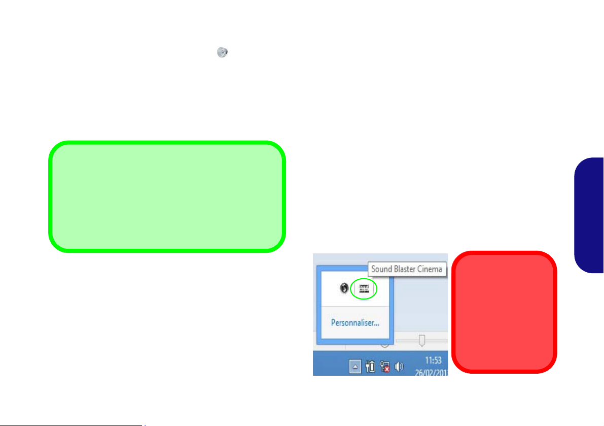
Caractéristiques audio
Réglages du Volume Sonore
Le niveau du volume sonore aussi peut également être réglé à l'aide du réglage du volume dans le menu Para-
mètres dans la barre des Charmes (dans l'écran
d'accueil) ou au moyen de l'icône Haut-parleurs de la
barre des tâches du bureau.
Sound Blaster
Cinema & HDMI
A noter que les effets
audio Sound Blaster
Cinema ne s'appliquent pas à l'audio généré via une
connexion HDMI.
Vous pouvez configurer les options audio de votre ordinateur
à partir du panneau de configuration Son
à partir de l'icône HD VDeck sur le bureau ou le panneau de
configuration VIA HD Audio Deck.
dans Windows,
Sound Blaster Cinema EQ
Installez l'application Sound Blaster Cinema afin de pouvoir configurer les paramètres audio adéquats permettant
d’obtenir les meilleures performances de jeux, de musique et
de films.
Le volume peut être réglé à l'aide de la combinaison de
touches Fn + F5/F6 ou au moyen de l'icône Haut-parleurs
de la barre des tâches.
Creative Software AutoUpdate
Exécutez l'application à partir du raccourci dans l'écran Applications et assurez-vous que vous êtes connecté à Internet,
puis cliquez sur Suivant et suivez les instructions à l'écran
pour mettre à jour le logiciel.
Application Sound Blaster Cinema
Exécutez le panneau de configuration Sound Blaster Cinema dans la zone de notification de la barre des tâches (ou à
partir de l'élément dans l'écran Applications). Cliquez sur
les onglets pour accéder aux menus du panneau de configuration.
Figure 12 - Sound Blaster Cinema
(Icône de zone de notification de la barre des tâches)
71
Français

Options d’alimentation
Figure 13 - Options d’alimentation
Le panneau de configuration Options d'alimentation de Windows vous permet de configurer la gestion d'alimentation de
votre ordinateur. Vous pouvez économiser de l'énergie à l'aide de modes de gestion de l'alimentation et configurer les op-
tions pour le bouton d'alimentation, bouton de veille (Fn + F4), couvercle de l'ordinateur (lorsqu'il est fermé), mode
Affichage et Veille (l'état d'économie d'énergie par défaut) dans le menu de gauche. Remarquez que le mode de gestion d'économie d'énergie peut avoir un impact sur les performances de l'ordinateur.
Cliquez pour sélectionner l'un des modes existants, ou cliquez sur Créer un mode de gestion d'alimentation dans le menu
gauche et sélectionnez les options pour créer un nouveau mode. Cliquez sur Modifier les paramètres du mode et cliquez
sur Modifier les paramètres d'alimentation avancés pour accéder à plus d'options de configuration.
Français
72

Installation du pilote
Directives générales pour
l'installation du pilote
D'une manière générale,
suivez les instructions par
défaut à l'écran pour chaque
pilote (par exemple Suivant
> Suivant > Terminer) à
moins que vous ne soyez un
utilisateur avancé. Dans la
plupart des cas, un redémarrage est nécessaire
pour installer le pilote.
Assurez-vous que les modules (par exemple WLAN
ou Bluetooth) sont allumés
avant d'installer le pilote correspondant.
Windows Update
Après avoir installé tous les
pilotes vérifiez que vous
avez activé Windows
Update afin d'obtenir toutes
les dernières mises à jour de
sécurité etc. (toutes les
mises à jour incluront les
derniers correctifs de Microsoft).
Installation des pilotes et alimentation
Lors de l'installation des pilotes assurez-vous
que votre ordinateur est alimenté par l'adaptateur CA/CC connecté à une source d'alimentation. Certains pilotes consomment une quantité
importante d'énergie pendant la procédure
d'installation, et si la capacité restante de la batterie n'est pas suffisante cela peut provoquer
l'arrêt du système et entraîner des problèmes
de système (à noter qu'il n'y a pas ici de problème de sécurité en cause, et la batterie sera
rechargeable en 1 minute).
Figure 14 - Installation du pilote
Le disque Device Drivers & Utilities + User’s Manual contient les pilotes et les utilitaires
nécessaires pour un bon fonctionnement de votre ordinateur. Cette installation aura probablement déjà été faite pour vous. Si ce n'est pas le cas, insérez le disque et cliquez sur Install
Drivers (bouton), ou Option Drivers (bouton) pour accéder au menu des pilotes Option-
nels. Installez les pilotes en respectant l'ordre indiqué dans la Figure 14. Cliquez pour sé-
lectionner les pilotes que vous désirez installer (vous devez noter les pilotes lorsque vous
les installez). Remarque: Si vous devez réinstaller un pilote, vous devez d’abord le désinstaller.
Installation manuelle du pilote
Cliquez le bouton Browse CD/DVD dans l'application Drivers Installer et naviguer jus-
qu'au fichier exécutable dans le dossier de pilote approprié.
Si l’assistant Nouveau matériel détecté apparaît pendant la procédure d'installation, cliquez
sur Annuler pour fermer l’assistant, et suivez la procédure d'installation comme indiqué.
Français
73

Module 3G
1
Orientation de la carte USIM
Notez que le côté lisible de la
carte USIM (avec les contacts
dorés) doit être orienté vers le
haut comme illustré.
Model A
1
1
(Optionnel pour Modèles A & B seulement)
Si votre option d'achat comporte un module 3G optionnel, suivez les instructions ci-dessous pour installer la carte USIM
(qui vous sera fournie par votre fournisseur de service), et installez ensuite l'application.
Insérer la carte USIM
1. Eteignez l'ordinateur, retournez-le et retirez la batterie (faites glisser le loquet dans la direction indiquée en dessous et sortez la batterie).
2. Insérez la carte USIM comme illustré ci-dessous jusqu'à ce qu'elle se clique en position, et remettez la batterie.
Français
Figure 15 - Retirer la batterie et insérer la carte USIM
74

Dépannage
Problème Cause possible - résolution
Les modules LAN sans fil/
Bluetooth ne peuvent pas être
détectés.
Le module caméra PC ne peut
pas être détecté.
Les fichiers vidéo capturés depuis
la caméra PC prennent trop de
place sur le disque.
Les modules sont désactivés quand l'ordinateur est en Mode Avion. Vérifiez l'indicateur LED
et/ou l’indicateur de la touche de fonction pour voir si l'ordinateur est en Mode Avion (voir
le Tableau 2 à la page 60). Utilisez la combinaison de touches Fn + F11 pour activer ou
désactiver le Mode Avion (voir le Tableau 4 à la page 62).
Le module est désactivé. Utilisez la combinaison de touche s Fn + F10 pour activer le module
(voir le Tableau 4 à la page 62). Exécutez l’application Caméra pour voir l'image de l'appareil
photo.
Notez que la capture de fichiers vidéo à haut e résolution nécess ite un esp ace subst antiel sur le
disque pour chaque fichier.
Notez que le système Windows nécessite un minimum de 20Go (64bit) d'espace libre sur la
partition système du lecteur C:. Il vous est recommandé d'enregistrer le fichier vidéo capturé
dans un autre emplacement que le lecteur C:, limitez la taille du fichier de la vidéo capturée ou
réduisez la résolution vidéo.
Français
75

Spécifications
Dernières informations de
spécification
Les spécifications énumérées dans
cette section sont correctes à l'heure de
la mise sous presse. Certains éléments
(particulièrement les types de processeur/vitesse unique) peuvent être modifiés ou mis à niveau en fonction du
calendrier des parutions du fabricant.
Voyez auprès de votre service clientèle
pour les détails.
Options de processeurs
Modèles A & C:
Processeur Intel® Core i7
Français
i7-4900MQ (2,80GHz)
Cache L3 8Mo, 22nm, DDR3L-1600MHz,
TDP 47W
i7-4800MQ (2,70GHz), i7-4700MQ (2,40GHz)
Cache L3 6Mo, 22nm, DDR3L-1600MHz,
TDP 47W
i7-4600M (2,9GHz)
Cache L3 4Mo, 22nm, DDR3L-1600MHz,
TDP 37W
Processeur Intel® Core i5
i5-4330M (2,80GHz), i5-4300M (2,60GHz),
i5-4200M (2,50GHz)
76
Cache L3 3Mo, 22nm, DDR3L-1600MHz,
TDP 37W
Processeur Intel® Core i3
i3-4100M (2,50GHz), i3-4000M (2,40GHz)
Cache L3 3Mo, 22nm, DDR3L-1600MHz,
TDP 37W
Processeur Intel®
3550M (2,30GHz)
Cache L3 2Mo, 22nm, DDR3L-1600MHz,
TDP 37W
Pentium®
Modèles B & D:
Processeur Intel® Core i7
i7-4900MQ (2,80GHz)
Cache L3 8Mo, 22nm, DDR3L-1600MHz,
TDP 47W
i7-4800MQ (2,70GHz), i7-4700MQ (2,40GHz)
Cache L3 6Mo, 22nm, DDR3L-1600MHz,
TDP 47W
i7-4600M (2,9GHz)
Cache L3 4Mo, 22nm, DDR3L-1600MHz,
TDP 37W
Processeur Intel® Core i5
i5-4330M (2,80GHz), i5-4300M (2,60GHz),
i5-4200M (2,50GHz)
Cache L3 3Mo, 22nm, DDR3L-1600MHz,
TDP 37W
Processeur Intel® Core i3
i3-4100M (2,50GHz), i3-4000M (2,40GHz)
Cache L3 3Mo, 22nm, DDR3L-1600MHz,
TDP 37W
Core logic
Chipset Intel® HM86
BIOS
AMI BIOS (SPI Flash ROM de 48Mb)
Mémoire
Deux emplacements SODIMM 204 broches,
supportant la mémoire DDR3L 1600MHz
Mémoire extensible jusqu’à 16Go
(La fréquence réelle d’opération de la
mémoire dépend du FSB du processeur.)
Stockage
(Option d’usine) Un module de lecteur
(12,7mm) échangeable (module de
optique
lecteur Super Multi/module de lecteur combo
Blu-Ray/module de lecteur graveur Blu-Ray)
(Option d’usine) 2nd HDD caddy 2,5"
9,5mm
Un disque dur SATA échangeable de 2,5"
9,5mm/7,0mm (H)
(Option d’usine) Un lecteur SSD mSATA
LCD
Modèles A & B:
15,6" (39,62cm) HD/FHD
Modèles C & D:
17,3" (43,94cm) HD+/FHD

Adaptateur Vidéo
GPU intégré Intel® et GPU discret NVIDIA
Prennent en charge Microsoft Hybrid
Graphics
Modèles A & C:
GPU intégré Intel® (le GPU dépend du
processeur)
Intel® HD Graphics 4600/Intel® HD
Graphics
Fréquence dynamique (Technologie de
mémoire vidéo dynamique d'Intel jusqu’à
1,7Go)
Compatible avec MS DirectX® 11
GPU discret NVIDIA
NVIDIA® GeForce 840M
RAM Vidéo interne GDDR3 2Go
Compatible avec MS DirectX® 11.1
Modèles B & D:
GPU intégré Intel® (le GPU dépend du
processeur)
Intel® HD Graphics 4600/Intel® HD
Graphics
Fréquence dynamique (Technologie de
mémoire vidéo dynamique d'Intel jusqu’à
1,7Go)
Compatible avec MS DirectX® 11
GPU discret NVIDIA
NVIDIA® GeForce GTX 850M
RAM Vidéo interne GDDR3 2Go
Compatible avec MS DirectX® 11.1
Son
Interface conforme HDA (Son Haute
Définition)
2 haut-parleurs intégrés
Microphone intégré
Sound Blaster™ Cinema
Sécurité
Fente de verrouillage de sécurité (type
Kensington)
Mot de Passe du BIOS
Clavier
Modèles A & B:
Clavier "Win Key" pleine taille (avec pavé
numérique)
Modèles C & D:
Clavier "Win Key" pleine taille (avec pavé
numérique)
(Option d’usine) Clavier lumineux "Win
Key" pleine taille (avec pavé numérique)
Dispositif de pointage
Touchpad intégré
Interface
Un port USB 2.0
Deux ports USB 3.0
Un port eSATA (port USB 3.0 combiné)
Un port de sortie HDMI
Un port moniteur externe
Une prise de sortie haut-parleurs/casque
Une prise d'entrée de microphone
Une prise réseau RJ-45
Une prise d’entrée en DC
Logements Mini-carte
Modèles A & B:
Logement 1 pour module LAN sans fil ou
module combo Bluetooth et LAN sans fil
(Option d’usine) Logement 2 pour module
3G ou lecteur SSD mSATA
Modèles C & D:
Logement 1 pour module LAN sans fil ou
module combo Bluetooth et LAN sans fil
(Option d’usine) Logement 2 pour lecteur
SSD mSATA
Lecteur de carte
Lecteur de carte multi-en-1
MMC (MultiMedia Card) /RS MMC
SD (Secure Digital) /Mini SD /SDHC /
SDXC
MS (Memory Stick) /MS Pro /MS Duo
Français
77

Communication
Gbit réseau Ethernet intégré
1,0M HD Caméra PC
(Option d’usine) 2,0M FHD Caméra PC
(Option d’usine - Modèles A & B
Seulement) Module Mini-carte 3G
Modules Half Mini-carte LAN sans fil/
Bluetooth:
(Option d’usine) Bluetooth 4.0 et LAN sans
fil (802.11a/c) Intel® Wireless-AC 7260
(Option d’usine) Bluetooth 4.0 et LAN sans
fil (802.11a/g/n) Intel® Wireless-N 7260
(Option d’usine) Bluetooth 4.0 et LAN sans
fil (802.11b/g/n) Intel® Wireless-N 7260
(Option d’usine) LAN sans fil (802.11b/g/n)
(tiers)
(Option d’usine) Bluetooth 4.0 et LAN sans
fil (802.11b/g/n) (tiers)
Spécifications environnementales
Français
Température
En fonction : 5
Eteint : -20°C - 60°C
Humidité relative
En fonction : 20% - 80%
Eteint : 10% - 90%
°C- 35°C
Mise en marche
Modèles A & C:
Adaptateur AC/DC pleine bande
Entrée AC: 100-240V, 50-60Hz
Sortie DC: 19V, 4,74A (90W)
(Option d’usine) Batterie Smart Lithium-Ion à
6 éléments, 62,16WH
(Option d’usine) Batterie Smart Lithium-Ion à
6 éléments, 48,84WH
Modèles B & D:
Adaptateur AC/DC pleine bande
Entrée AC: 100-240V, 50-60Hz
Sortie DC: 19,5V, 6,15A (120W)
(Option d’usine) Batterie Smart Lithium-Ion à
6 éléments, 62,16WH
(Option d’usine) Batterie Smart Lithium-Ion à
6 éléments, 48,84WH
Dimensions physiques & poids
Modèles A & B:
374 (l) x 252 (p) x 14 - 31,4 (h) mm
OU
374 (l) x 249,5 (p) x 14,8 - 32,8 (h) mm
2,5kg (avec lecteur optique & batterie
48,84WH)
78
Modèles C & D:
413 (l) x 272,8 (p) x 36,4 (h) mm
3,1kg (avec lecteur optique & batterie
62,16WH)

Acerca de esta Guía del Usuario Concisa
Esta guía rápida es una breve introducción para poner su sistema en funcionamiento. Es un suplemento y no un sustituto del
Manual del usuario completo en inglés en formato Adobe Acrobat del disco Device Drivers & Utilities + User's Manual
suministrado con el ordenador. En este disco también se encuentran los controladores y utilitarios necesarios para utilizar el
ordenador correctamente (Nota:
previo aviso).
Algunas o todas las características del ordenador pueden haberse configurado de antemano. Si no lo están, o si desea
reconfigurar (o reinstalar) partes del sistema, consulte el Manual del usuario completo. El disco Device Drivers & Utilities
+ User’s Manual no contiene un sistema operativo.
Información de regulación y seguridad
Por favor, preste especial atención a todos los avisos de regulación e información de seguridad contenidos en el Manual del
usuario completo del disco Device Drivers & Utilities + User’s Manual.
© Enero 2014
Marcas registradas
Intel, Intel Core y Pentium son marcas/marcas registradas de Intel Corporation.
La compañía se reserva el derecho a revisar esta publicación o cambiar su contenido sin
Español
79

Instrucciones para el cuidado y funcionamiento
El ordenador portátil es muy robusto, pero puede dañarse. Para
evitar esto, siga estas sugerencias:
• No lo deje caer ni lo exponga a golpes fuertes. Si el ordena dor se
cae, la carcasa y los componentes podrían dañarse.
• Manténgalo seco y no lo sobrecaliente. Mantenga el ordenador y
fuente de alimentación alejados de cualquier tipo de fuente de
calor. Esto es un apara to eléctrico. Si se derrama agua u otro líquido
en su interior, el ordenador podría dañarse seriamente.
• Evite las interferencias. Mantenga el ordenador alejado de trans-
formadores de alta capacidad, motores eléctricos y otros campos
magnéticos fuertes. Éstos pueden dificultar el correcto funcionamiento y dañar los datos.
• Siga las instrucciones apropiadas de manejo del ordenador.
Apague el ordenador correctamente y no olvide guardar su trabajo.
Recuerde guardar periódicamente sus datos, pues los datos pueden
perderse si la batería se descarga.
Servicio
Si intenta reparar el ordenador usted mismo, podría anular la
garantía y exponerse usted y el ordenador a descarga eléctrica.
Deje que sea personal de reparación cualificado el que realice
las reparaciones, especialmente bajo cualquiera de estas condi-
Español
ciones:
• Cuando el cable de alimentación o adaptador AC/DC esté dañado o
pelado.
• Si el ordenador ha estado expuesto a la lluvia u otros líquidos.
• Si el ordenador no funciona con normalidad tras seguir las instrucciones de uso.
• Si el ordenador se ha caído o dañado (no toque el líquido venenoso
si el panel LCD se rompe).
• Si hay un olor fuera de lo normal, calor o humo que sale del ordenador.
Información de seguridad
• Utilice solamente un adaptador de alimentación aprobado para su
uso con este ordenador.
• Utilice solamente el cable de corriente y las baterías indicados en
este manual. No tire las baterías al fuego. Podrían explotar. Consulte los códigos locales para posibles instrucciones para desechos
especiales.
• Nunca utilice una batería que se haya caído o que parezca dañada
(p. ej. doblada o retorcida). Incluso si el ordenador sigue funcionando con una batería dañada, puede provocar daños en el circuito
que podrían causar fuego.
• Compruebe que su ordenador esté completamente apagado antes de
introducirlo en una bolsa de viaje (o en cualquier funda).
• Antes de limpiar el ordenador, quite la batería y asegúrese de que el
ordenador esté desconectado de cualquier fuente de alimentación
externa, periféricos y cables (incluyendo la línea telefónica).
• Utilice un trapo limpio y suave para limpiar el ordenador, pero no
aplique limpiador directamente en el ordenador. No utilice limpiadores volátiles (derivados del petróleo) o limpiadores abrasivos en
ningún lugar del ordenador.
• No intente reparar baterías. Solicite la reparación o la sustitución a
su representante de servicio o a personal de servicio cualificado.
• Tenga en cuenta que en ordenadores con logotipos de LCD etiquetados eléctricamente en relieve, el logotipo está recubierto por un
adhesivo protector. Debido al desgaste y rotura normales, este
adhesivo puede deteriorarse con el tiempo y en el logotipo expuesto
pueden formarse bordes afilados. Tenga cuidado al manipular el
ordenador en este caso y evite tocar el logotipo del LCD etiquetado
eléctricamente. Evite colocar cualquier elemento en la bolsa de
transporte que pueda rozar la parte superior del ordenador durante
el transporte Si ocurre un desgaste o rotura, contacte con el centro
de servicios.
80

Precauciones para baterías de polímero
Eliminación de la batería & Cuidado
El producto que usted ha comprado contiene una batería
recargable. La batería es reciclable Terminada su vida útil,
según las leyes locales y estatales, puede ser ilegal
desecharla junto con los residuos ordinarios. Verifique con las
autoridades locales responsables de los desechos sólidos
cuáles son las opciones de eliminación y reciclado existentes
en su zona.
Peligro de explosión si la batería está mal colocada.
Sustitúyala con un tipo de batería igual o equivalente al
recomendado por el fabricante. Elimine la batería usada de
conformidad con las instrucciones del fabricante.
Tenga en cuenta la información siguiente específica para baterías de polímero; además, donde corresponda, invalida la información sobre precauciones para baterías normales.
• Las baterías pueden aumentar o hincharse ligeramente, sin embargo,
esto es parte del mecanismo de seguridad de la batería y o supone un
problema.
• Utilice los procedimientos de manejo apropiados cuando utilice
baterías de polímero. No utilice baterías de polímero en entornos
con temperatura ambiental alta y no guarde las baterías sin usar
durante mucho tiempo.
Español
81

Guía rápida para empezar
Apagar
Por favor, tenga en cuenta que debería siempre apagar el ordenador eligiendo la opción
Apagar en Windows (ver abajo). Esto le ayu-
dará a evitar problemas con el disco duro o el
sistema.
Haga clic en Configuración en la Barra
Charms (utilice la combinación Tecla de Win-
dows
+ tecla C para acceder a la Barra
Charms) y elige la opción Apagar desde el
menú Iniciar/Apagar.
O
Elige Apagar o cerrar
sesión > Apagar en el
menú contextual (utilice la combinación Tecla
de Windows
+ tecla X para acceder al
menú contextual).
130°
Figura 1 - Abrir la tapa/LCD/ordenador con el adaptador AC/DC en-
chufado
1. Quite todos los materiales del embalaje.
2. Coloque el ordenador en una superficie estable.
3. Inserte la batería y asegúrese de que quede
bloqueada en su posición.
4. Conecte en los puertos correspondientes los
periféricos que desee utilizar con el ordenador (p.
ej. teclado y ratón).
5. Conecte el adaptador AC/DC al conector de
entrada DC que está del lado izquierdo del
ordenador, y luego conecte el cable de
alimentación AC en un eschufe y al adaptador.
6. Utilice una mano para levantar con cuidado la
tapa/LCD a un ángulo de visión cómodo (no
exceder 130 grados), mientras utiliza la otra mano
(como se muestra en la Figura 1) para sostener
la base del ordenador (Nota: Nunca levante el
ordenador por la tapa/LCD).
7. Presione el botón de encendido para “encender”.
Software de sistema
Puede ser que su ordenador tenga instalado un
software de sistema. Si no es el caso, o si desea
reconfigurarlo con otro sistema, este manual se
Español
refiere a Microsoft Windows 8.1.
82

Diferencias de modelos
Esta serie de portátil incluye cuatro tipos de modelos distintos que principalmente se diferencian según se indica en la siguiente tabla
Característica Modelo A Modelo B Modelo C Modelo D
.
Adaptador de
vídeo
LCD
Módulo 3G
Alimentación
GPU integrada de Intel®
(Intel® HD Graphics
4600/Intel® HD Graphics)
y GPU discreta NVIDIA®
(NVIDIA® GeForce
840M
)
15,6" (39,62cm) HD/FHD 17,3" (43,94cm) HD+/FHD
Opción No
Salida DC: 19V, 4,74A
(90W)
GPU integrada de Intel®
(Intel® HD Graphics
4600/Intel® HD Gra-
phics) y GPU discreta
NVIDIA® (NVIDIA®
GeForce GTX
Salida DC: 19,5V, 6,15A
(120W)
850M
GPU integrada de Intel®
(Intel® HD Graphics
4600/Intel® HD Gra-
phics) y GPU discreta
NVIDIA® (NVIDIA®
)
Salida DC: 19V, 4,74A
Tabla 1 - Diferencias de modelos
GeForce
(90W)
840M
GPU integrada de Intel®
(Intel® HD Graphics
4600/Intel® HD Graphics)
y GPU discreta NVIDIA®
(NVIDIA® GeForce GTX
)
Salida DC: 19,5V, 6,15A
850M
(120W)
)
Español
83

Mapa del sistema: Vista frontal con panel LCD abierto
Uso de dispositivos
inalámbricos a bordo
El uso de dispositivos electrónicos portátiles a bordo de un avión
suele estar prohibido.
Asegúrese de que los módulos
WLAN y Bluetooth estén
apagados si utiliza el equipo en
un avión ajustando el sistema al
Modo de avión.
Figura 2
Vista frontal con panel LCD
abierto (Modelos A & B)
1. Cámara PC
2. Micrófono incorporado
3. *LED de cámara PC
*Cuando la cámara PC esté en
uso, el LED se iluminará en rojo.
4. Panel LCD
5. Botón de encendido
6. Indicadores LED
7. Teclado
8. Touchpad (almohadilla táctil) y
botones
Tenga en cuenta que el área válida
de operación del Touchpad y los
botones es la indicada dentro de
las líneas de puntos.
5
7
6
2
1
3
4
8
8
(Modelos A & B)
Español
84
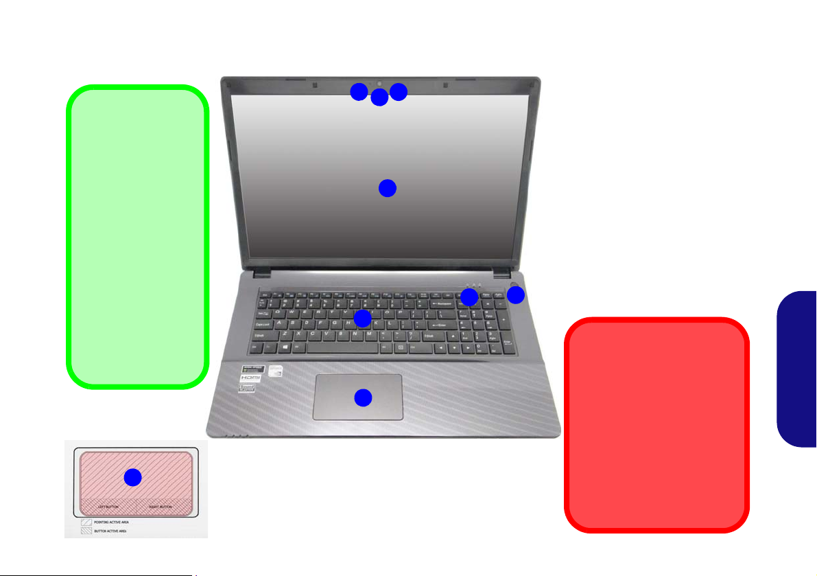
Mapa del sistema: Vista frontal con panel LCD abierto
Uso de dispositivos
inalámbricos a bordo
El uso de dispositivos electrónicos portátiles a bordo de un
avión suele estar prohibido.
Asegúrese de que los módulos
WLAN y Bluetooth estén
apagados si utiliza el equipo en
un avión ajustando el sistema al
Modo de avión.
Figura 3
Vista frontal con panel LCD
abierto (Modelos C & D)
1. Cámara PC
2. Micrófono incorporado
3. *LED de cámara PC
*Cuando la cámara PC esté en
uso, el LED se iluminará en
rojo.
4. Panel LCD
5. Botón de encendido
6. Indicadores LED
7. Teclado
8. Clickpad/Touchpad
5
7
6
2
1
3
4
8
Sensibilidad
Clickpad/Touchpad
Las zonas de los botones del ratón de la parte inferior de la
plataforma mide unos
15mm desde la parte
inferior de ésta y los
botones izquierdo y
derecho están divididos por la mitad como
se ilustra a continuación. Presione la zona
del botón izquierdo
para clic izquierdo y la
del botón derecho para
hacer clic derecho.
8
(Modelos C & D)
Español
85

Indicadores LED
Los indicadores LED en su ordenador muestran una valiosa
información sobre el estado actual del ordenador.
Icono Color Descripción
Icono Color Descripción
Español
86
Naranja
Verde El ordenador está encendido
Verde
parpadeante
Naranja La batería se está cargando
Verde
Naranja
parpadeante
Verde
Verde
El adaptador AC/DC está conec-
tado
El ordenador está en modo Sus-
pensión
La batería está completamente
cargada
La batería ha alcanzado el
estado crítico de poca energía
El disco duro/dispositivo óptico
está en uso
El Modo de avión está activado
(los módulos WLAN, 3G y Blue-
tooth están apagados)
Tabla 2 - Indicadores LED de encendido
Azul
Azul El bloqueo de mayúsculas está activado
Azul
El teclado numérico (NumLk) está acti-
vado
El bloqueo de desplazamiento está acti-
vado
Tabla 3 - Indicadores LED de estado

Teclado
Keys
Numeric
Keypad
Keypad
Tecla de Windows
Tecla Menú/Aplicación
Acceso directo del
teclado al logotipo
Windows
Utilice la combinación de teclas Tecla de Windows
+ D para cambiar de la
pantalla Inicio al Escritorio
de Windows.
Acceso directo del
teclado a Menú/
Aplicación
Cuando la app del Escritorio
esté en ejecución, puede
usar la tecla Menú/Aplica-
ción del teclado para
que actúe como clic del botón derecho de un ratón. En
la pantalla Inicio esta función resulta útil para mostrar
rápidamente la barra Per-
sonalizar.
Teclado
Tecla Fn
Teclas de función
numérico
Bloq Num &
BloqDespl
Tecla de Windows
Tecla Menú/Aplicación
Teclado
Tecla Fn
Teclas de función
numérico
Bloq Num &
BloqDespl
Modelos A & B
Modelos C & D
El teclado tiene un teclado numérico para una entrada fácil de datos numéricos. Al presionar Fn + Bloq Num (Modelos A &
B)/Bloq Num (Modelos C & D) el teclado numérico se habilita o inhabilita. También incluye las teclas de función para
permitirle cambiar las características operacionales al instante.
(Sólo teclados iluminados)
Fn + F12.
Puede ajustar el nivel de iluminación del teclado, o apagarlo y encenderlo, utilizando las teclas
Figura 4 - Teclado
Español
87

Teclas de función
Las teclas de función (F1 - F11 etc.) actuarán como teclas directas (Hot-Key) cuando se pulsan junto con la tecla Fn. Además
de las combinaciones de teclas de función básicas algunos indicadores visuales están disponibles (sólo en la aplicación
Escritorio de Windows y no en la pantalla Inicio) cuando el controlador de teclas directas está instalado.
Teclas Función/indicadores visuales Teclas Función/indicadores visuales
Fn +
Fn +
Fn +
Fn + Conmutación mudo
Fn + Conmutación dormir
Español
Fn +
Fn + F8/F9
Fn +
Reproducir/pausar (en los programas audio/vídeo)
Activar/desactivar el
Touchpad
Apagar luz de fondo del LCD (presione una tecla o
utilice el Touchpad para encenderlo)
Reducción/aumento
volumen de sonido
Cambiar la configuración de pantalla (ver la
página 96)
Reducción/aumento bri-
llo LCD
Tabla 4 - Teclas de función & indicadores visuales
Fn +
Fn +
Fn +
/
Fn +
Fn +
Fn +
Fn +
Activar/desactivar el
módulo cámara PC
Cambiar Modo de
avión
Encender o apagar la iluminación del teclado/
Ajustar el nivel del brillo
(Sólo teclados iluminados)
Activar/disactivar el
teclado numérico
Cambiar el bloqueo de
desplazamiento
Cambio Bloq. Mayús-
culas
Cambiar Control Center (centro de control)
(ver la página 89)
Control automático del
ventilador/potencia
completa
88

Control Center (Centro de control)
Presione la combinación de teclas Fn + Esc o haga doble clic en el icono en el área de notificación de la barra de tareas
para activar o desactivar el Control Center (Centro de control) en la aplicación Escritorio de Windows (no en la pantalla
Inicio). El Control Center (Centro de control) ofrece un acceso rápido a los controles usados con más frecuencia y le permite
activar, y desactivar módulos rápidamente.
Figura 5 - Control Center
Haga clic en cualquier botón para activar o desactivar cualquiera de los módulos (p.ej. Touchpad, Cámara). Haga clic en
Power Conservation (Ahorro de energía) para cambiar entre los modos Performance (Rendimiento), Balanced
(Equilibrado) o Energy Star. Haga clic en los botones (o simplemente haga clic y mantenga presionado el botón del ratón)
para ajustar el control deslizante del Brightness/Volume (Brillo/Volumen). Haga clic en Display Switch (Cambiar pantalla)/
Time Zone (Zona horaria)/Desktop Background (Fondo de pantalla) para abrir el panel de control de Windows adecuado.
Haga clic en el botón Suspensión para cambiar el equipo a los modos Hibernar o Suspender.
Español
89

Power Status (Estado de energía)
El icono Estado de energía mostrará si la alimentación
actual viene dada por la batería o por el adaptador AC/DC
enchufado en una toma de corriente. La barra de estado de
energía muestra el estado actual de la carga de la batería.
Sleep (Suspender)
Haga clic en el botón Suspender para abrir los botones
Hibernar
botones para que el equipo entre en el modo de ahorro de
energía elegido.
o Suspender y haga clic en uno de esos
Brightness (Brillo)
El icono Brillo mostrará el nivel actual del brillo de la
pantalla. Puede usar el control deslizante para ajustar el brillo
de la pantalla o las combinaciones de teclas Fn + F8/F9 o
usar la combinación de teclas Fn + F2 para apagar la
retroiluminación LED (presione una tecla para volver
encenderla). Tenga en cuenta que Modo de energía también
puede afectar el brillo de la pantalla.
Volume (Volumen)
El icono Volumen mostrará el nivel actual del volumen.
También puede usar el control deslizante para ajustar el
volumen o las combinaciones de teclas Fn + F5/F6 o la
combinación de teclas Fn + F3 para silenciar el volumen.
Power Conservation (Ahorro de energía)
Este sistema soporta las características de administración de
Español
energía Energy Star que hace que los equipos (CPU, disco
duro, etc.) entren en modos de ahorro de energía y suspensión
tras el período de tiempo de inactividad designado. Haga clic
en el botón Performance (Rendimiento), Balanced
(Equilibrado) o Energy Star.
Display Switch (Cambiar pantalla)
Haga clic en el botón Cambiar pantalla para acceder al
menú (o utilice la combinación de teclas + P) y
seleccione el modo de pantalla apropiado.
Time Zone (Zona horaria)
Si hace clic en el botón Zona horaria accederá al panel de
control Fecha y hora de Windows.
Desktop Background (Fondo de pantalla)
Si hace clic en el botón Fondo de pantalla podrá cambiar la
imagen del fondo del escritorio.
Touchpad/cámara PC
Haga clic en cualquiera de estos botones para cambiar el
estado de energía del Touchpad o del módulo cámara.
Aparecerá una cruz en la esquina superior izquierda del
icono cuando esté apagado. Tenga en cuenta que el
estado de energía del módulo cámara también queda
afectado por el Modo de energía seleccionado.
90

Mapa del sistema: Vistas frontal, izquierda, derecha, posterior e
Figura 6 - Vistas frontal, izquierda, derecha, posterior e in-
ferior (Modelos A & B)
1. Indicadores LED
2. Lector de tarjetas multi-en-1
3. Conector de entrada DC
4. Rejilla
5. Puerto para monitor externo
6. Conector LAN RJ-45
7. Puerto combinado eSATA/
USB 3.0
8. Puerto de salida de HDMI
9. Puertos USB 3.0
10. Conector de entrada para
micrófono
11. Conector de salida de
auriculares
12. Puerto USB 2.0
13. Bahía de dispositivo óptico
14. Orificio de expulsión de
emergencia
15. Ranura del cierre de
seguridad
16. Ubicación de la batería
17. Tapa de la bahía
componente
18. Altavoces incorporados
1
16
2
8
4
6
3
5
9
7
17
18
18
2
16
Recalentamiento
Para evitar que su ordenador se
recaliente compruebe que nada bloquea
la(s) rejilla(s) con el equipo encendido.
Expulsión de emergencia del disco
Si necesita expulsar un disco
manualmente (p. ej. por un corte de
corriente inesperado) puede in troducir la
punta de un clip en el orificio de expulsión
de emergencia. No utilice la punta de un
lápiz u otros objetos que puedan romperse
y quedar atrapados en el orificio.
Puerto USB
3.0
USB 3.0 transfiere los datos
mucho más rápido que USB
2.0 y es compatible con su
antecesor
USB 2.0.
14
10
12
13
15
11
Cara inferior
Parte frontal
Lateral izquierdo
Parte posterior
Lateral derecho
4
4
9
inferior (Modelos A & B)
Español
91

Mapa del sistema: Vistas frontal, izquierda, derecha, posterior e
Figura 7 - Vistas frontal, izquierda, derecha, posterior e in-
ferior (Modelos C & D)
1. Indicadores LED
2. Lector de tarjetas multi-en-1
3. Conector de entrada DC
4. Rejilla
5. Puerto para monitor externo
6. Conector LAN RJ-45
7. Puerto combinado eSATA/
USB 3.0
8. Puerto de salida de HDMI
9. Puertos USB 3.0
10. Conector de entrada para
micrófono
11. Conector de salida de
auriculares
12. Puerto USB 2.0
13. Bahía de dispositivo óptico
14. Orificio de expulsión de
emergencia
15. Ranura del cierre de
seguridad
16. Batería
17. Tapa de la bahía
componente
18. Altavoces incorporados
Recalentamiento
Para evitar que su ordenador se
recaliente compruebe que nada bloquea
la(s) rejilla(s) con el equipo encendido.
Expulsión de emergencia del disco
Si necesita expulsar un disco
manualmente (p. ej. por un corte de
corriente inesperado) puede introducir la
punta de un clip en el orificio de expulsión
de emergencia. No utilice la punta de un
lápiz u otros objetos que puedan romperse
y quedar atrapados en el orificio.
Puerto USB
3.0
USB 3.0 transfiere los datos
mucho más rápido que USB
2.0 y es compatible con su
antecesor
USB 2.0.
Cara inferior
1
14
16
2
8
4
6
3
5
10
12
9
7
13
15
17
4
18
18
16
11
9
4
4
4
Parte frontal
Lateral izquierdo
Parte posterior
Lateral derecho
inferior (Modelos C & D)
Español
92

Panel de Control de Windows 8.1
Figura 8
Menú contextual
Mueva el ratón a la esquina
inferior izquierda de la pantalla y haga clic con el botón
derecho en el botón Inicio
para acceder al menú.
Figura 9 - Pantalla Inicio
A lo largo de este manual verá una instrucción para abrir el Panel de Control. Haga clic con el botón derecho en el botón
Inicio en la app del Escritorio o en la pantalla Inicio (o utilice la combinación Tecla de Windows + tecla X) para abrir
un menú contextual avanzado con características útiles como Panel de control, Programas y características, Opciones de
energía, Administrador de tareas, Buscar, Explorador de archivos, Símbolo del sistema, Administrador de dispositivos,
Conexiones de red, etc y seleccionar Panel de Control.
Pantalla Inicio y escritorio de Windows
8.1
A las apps, paneles de control, utilidades y programas en Windows se
accede desde la pantalla Inicio y/o desde la app Escritorio de
Windows. Al Escritorio (que se ejecuta como una app dentro de la
pantalla Inicio) se puede acceder haciendo clic en Escritorio en la
pantalla Inicio (o usando la combinación Tecla de Windows + tecla
D). La barra de tareas aparecerá en la parte inferior de la pantalla del
escritorio y verá el área de notificación de la barra de tareas en la parte
inferior derecha de la pantalla. Haga clic en la flecha en la parte inferior
de la pantalla Inicio para acceder a Aplicaciones.
Español
93

Apps y Mosaicos
Haga clic en la flecha en la parte inferior de
la pantalla Inicio para acceder a Aplicaciones.
La pantalla Inicio contendrá varias apps y muchas más se instalarán
conforme añada más aplicaciones, etc. No todas estas apps caben en una
pantalla, por lo que a menudo deberá usar el control deslizante de la parte
inferior de la pantalla para ver todas las apps necesarias.
Barra Charms
El lado derecho de la pantalla muestra la barra Charms. La barra Charms contiene los menús Buscar, Compartir, Inicio,
Dispositivos y Configuración. Para acceder a la barra Charms, mueva el cursor hacia la esquina superior o inferior derecha
de la pantalla y luego mueva uno de los elementos hacia la barra Charms para activarla (la barra estará en negro cuando esté
activa) o utilice la combinación Tecla de Windows + tecla C.
Español
94
Figura 10 - Pantalla Inicio con la barra Charms

Parámetros de vídeo
El sistema incluye una GPU integrada de Intel (para el
ahorro de energía) y una GPU discreta NVIDIA (para
mayor rendimiento). Puede cambiar los dispositivos de
pantalla y configurar las opciones de pantalla desde el panel
de control en Windows siempre que tenga instalado el
controlador de vídeo.
Microsoft Hybrid Graphics
Microsoft Hybrid Graphics es una tecnología sin
interrupciones diseñada para obtener el mejor rendimiento
del sistema de gráficos permitiendo una mayor duración de
la batería, sin tener que cambiar la configuración
manualmente. El ordenador cambiará automáticamente y sin
interrupción entre la UMA (Unified Memory Architecture)
integrada, la GPU (iGPU) y la GPU (dGPU) discreta cuando
la aplicación en uso lo requiera.
Para acceder al panel de control Pantalla:
1. Vaya al Panel de Control.
2. Haga clic en Pantalla (icono) - en Apariencia y
personalización (categoría).
3. Haga clic en Ajustar resolución de pantalla/Ajustar
resolución.
O
4. Haga clic con el botón derecho en el escritorio (utilice la
combinación Tecla de Windows + tecla D para acceder al
escritorio) y seleccione Resolución de pantalla.
5. Utilice el cuadro desplegable para seleccionar la resolución de la
pantalla.
6. Haga clic en Configuración avanzada.
Para acceder al Panel de control de gráficos HD Intel®:
1. Haga clic en el icono (Panel de control de gráficos HD Intel®)
en la pantalla Aplicaciones.
O
2. Haga clic con el botón derecho en el escritorio (utilice la
combinación Tecla de Windows + tecla D para acceder al
escritorio) y seleccione Propiedades de gráficos en el menú.
O
3. Haga clic en el icono en el área de notificación de la barra
de tareas del escritorio y seleccione Propiedades de gráficos
en el menú.
Para acceder al Panel de control de NVIDIA:
1. Vaya al Panel de Control.
2. Haga clic en Panel de control de NVIDIA (icono) - en
Apariencia y personalización (categoría).
O
3. Haga clic con el botón derecho en el escritorio (utilice la
combinación Tecla de Windows + tecla D para acceder al
escritorio) y seleccione Panel de control de NVIDIA en el
menú.
Español
95

Dispositivos y opciones de pantalla
Resolución de pantalla para Apps (Windows 8.1)
La resolución mínima en la que las apps se ejecutarán es de
1024x768.
La resolución mínima necesaria para soportar todas las
características de Windows 8.1 (incluyendo multitarea con
snap) es de 1366x768.
Figura 11
+ P (Cambiar la
configuración de
pantalla)
Además del LCD incorporado, también puede utilizar un
monitor VGA/pantalla plana o TV (conectado al puerto para
monitor externo o al puerto de salida de HDMI) como
dispositivo de pantalla.
Español
Usar la combinación de teclas del
logotipo Windows
+ P para cambiar
entre pantallas
Puede usar la combinación de teclas + P (o Fn + F7) para
cambiar rápidamente la configuración de pantalla y los
modos (esto resulta especialmente útil cuando se coloca un
proyector) en Windows.
1. Conecte una pantalla externa al puerto para monitor externo o
puerto de salida de HDMI y enciéndala.
2. Pulse la combinación de teclas + P (o Fn + F7).
3. Aparecerá un menú en pantalla.
4. Utilice las teclas del cursor (o + P) para seleccionar la
configuración apropiada en el menú y presione Entrar para
confirmar la selección.
96
 Loading...